EP2726596B1 - Bioreactor chamber - Google Patents
Bioreactor chamber Download PDFInfo
- Publication number
- EP2726596B1 EP2726596B1 EP12720563.1A EP12720563A EP2726596B1 EP 2726596 B1 EP2726596 B1 EP 2726596B1 EP 12720563 A EP12720563 A EP 12720563A EP 2726596 B1 EP2726596 B1 EP 2726596B1
- Authority
- EP
- European Patent Office
- Prior art keywords
- cap
- gas
- base
- chamber
- liquid
- Prior art date
- Legal status (The legal status is an assumption and is not a legal conclusion. Google has not performed a legal analysis and makes no representation as to the accuracy of the status listed.)
- Not-in-force
Links
- 239000007788 liquid Substances 0.000 claims description 134
- 239000012530 fluid Substances 0.000 claims description 38
- 239000000523 sample Substances 0.000 claims description 25
- 239000012472 biological sample Substances 0.000 claims description 9
- 238000000034 method Methods 0.000 claims description 9
- 238000007789 sealing Methods 0.000 claims description 5
- 238000004891 communication Methods 0.000 claims description 4
- 238000000926 separation method Methods 0.000 claims description 3
- 239000007789 gas Substances 0.000 description 77
- 230000015572 biosynthetic process Effects 0.000 description 22
- 238000005755 formation reaction Methods 0.000 description 22
- 230000013011 mating Effects 0.000 description 15
- 238000001727 in vivo Methods 0.000 description 7
- 239000007791 liquid phase Substances 0.000 description 7
- 230000002572 peristaltic effect Effects 0.000 description 6
- 238000002474 experimental method Methods 0.000 description 5
- 238000012258 culturing Methods 0.000 description 4
- 238000000338 in vitro Methods 0.000 description 4
- 239000012620 biological material Substances 0.000 description 3
- 230000007246 mechanism Effects 0.000 description 3
- 239000002609 medium Substances 0.000 description 3
- 239000012071 phase Substances 0.000 description 3
- 238000005086 pumping Methods 0.000 description 3
- 230000007423 decrease Effects 0.000 description 2
- 238000011161 development Methods 0.000 description 2
- 230000018109 developmental process Effects 0.000 description 2
- 239000007792 gaseous phase Substances 0.000 description 2
- 239000001963 growth medium Substances 0.000 description 2
- 210000004072 lung Anatomy 0.000 description 2
- 210000002345 respiratory system Anatomy 0.000 description 2
- 230000009471 action Effects 0.000 description 1
- 238000000429 assembly Methods 0.000 description 1
- 230000000712 assembly Effects 0.000 description 1
- 230000004323 axial length Effects 0.000 description 1
- 230000008901 benefit Effects 0.000 description 1
- 230000008878 coupling Effects 0.000 description 1
- 238000010168 coupling process Methods 0.000 description 1
- 238000005859 coupling reaction Methods 0.000 description 1
- 230000003247 decreasing effect Effects 0.000 description 1
- 230000000694 effects Effects 0.000 description 1
- 230000007613 environmental effect Effects 0.000 description 1
- 230000004941 influx Effects 0.000 description 1
- 238000007689 inspection Methods 0.000 description 1
- 239000000463 material Substances 0.000 description 1
- 238000004264 monolayer culture Methods 0.000 description 1
- 238000000465 moulding Methods 0.000 description 1
- 230000001575 pathological effect Effects 0.000 description 1
- 230000035479 physiological effects, processes and functions Effects 0.000 description 1
- 239000011148 porous material Substances 0.000 description 1
- 230000002062 proliferating effect Effects 0.000 description 1
- 230000035755 proliferation Effects 0.000 description 1
- 238000011160 research Methods 0.000 description 1
- 239000000126 substance Substances 0.000 description 1
- 239000000758 substrate Substances 0.000 description 1
- 231100000027 toxicology Toxicity 0.000 description 1
- 238000011179 visual inspection Methods 0.000 description 1
Images


Classifications
-
- C—CHEMISTRY; METALLURGY
- C12—BIOCHEMISTRY; BEER; SPIRITS; WINE; VINEGAR; MICROBIOLOGY; ENZYMOLOGY; MUTATION OR GENETIC ENGINEERING
- C12M—APPARATUS FOR ENZYMOLOGY OR MICROBIOLOGY; APPARATUS FOR CULTURING MICROORGANISMS FOR PRODUCING BIOMASS, FOR GROWING CELLS OR FOR OBTAINING FERMENTATION OR METABOLIC PRODUCTS, i.e. BIOREACTORS OR FERMENTERS
- C12M29/00—Means for introduction, extraction or recirculation of materials, e.g. pumps
- C12M29/10—Perfusion
-
- C—CHEMISTRY; METALLURGY
- C12—BIOCHEMISTRY; BEER; SPIRITS; WINE; VINEGAR; MICROBIOLOGY; ENZYMOLOGY; MUTATION OR GENETIC ENGINEERING
- C12M—APPARATUS FOR ENZYMOLOGY OR MICROBIOLOGY; APPARATUS FOR CULTURING MICROORGANISMS FOR PRODUCING BIOMASS, FOR GROWING CELLS OR FOR OBTAINING FERMENTATION OR METABOLIC PRODUCTS, i.e. BIOREACTORS OR FERMENTERS
- C12M23/00—Constructional details, e.g. recesses, hinges
- C12M23/02—Form or structure of the vessel
- C12M23/08—Flask, bottle or test tube
-
- C—CHEMISTRY; METALLURGY
- C12—BIOCHEMISTRY; BEER; SPIRITS; WINE; VINEGAR; MICROBIOLOGY; ENZYMOLOGY; MUTATION OR GENETIC ENGINEERING
- C12M—APPARATUS FOR ENZYMOLOGY OR MICROBIOLOGY; APPARATUS FOR CULTURING MICROORGANISMS FOR PRODUCING BIOMASS, FOR GROWING CELLS OR FOR OBTAINING FERMENTATION OR METABOLIC PRODUCTS, i.e. BIOREACTORS OR FERMENTERS
- C12M23/00—Constructional details, e.g. recesses, hinges
- C12M23/22—Transparent or translucent parts
-
- C—CHEMISTRY; METALLURGY
- C12—BIOCHEMISTRY; BEER; SPIRITS; WINE; VINEGAR; MICROBIOLOGY; ENZYMOLOGY; MUTATION OR GENETIC ENGINEERING
- C12M—APPARATUS FOR ENZYMOLOGY OR MICROBIOLOGY; APPARATUS FOR CULTURING MICROORGANISMS FOR PRODUCING BIOMASS, FOR GROWING CELLS OR FOR OBTAINING FERMENTATION OR METABOLIC PRODUCTS, i.e. BIOREACTORS OR FERMENTERS
- C12M23/00—Constructional details, e.g. recesses, hinges
- C12M23/38—Caps; Covers; Plugs; Pouring means
-
- C—CHEMISTRY; METALLURGY
- C12—BIOCHEMISTRY; BEER; SPIRITS; WINE; VINEGAR; MICROBIOLOGY; ENZYMOLOGY; MUTATION OR GENETIC ENGINEERING
- C12M—APPARATUS FOR ENZYMOLOGY OR MICROBIOLOGY; APPARATUS FOR CULTURING MICROORGANISMS FOR PRODUCING BIOMASS, FOR GROWING CELLS OR FOR OBTAINING FERMENTATION OR METABOLIC PRODUCTS, i.e. BIOREACTORS OR FERMENTERS
- C12M23/00—Constructional details, e.g. recesses, hinges
- C12M23/46—Means for fastening
-
- C—CHEMISTRY; METALLURGY
- C12—BIOCHEMISTRY; BEER; SPIRITS; WINE; VINEGAR; MICROBIOLOGY; ENZYMOLOGY; MUTATION OR GENETIC ENGINEERING
- C12M—APPARATUS FOR ENZYMOLOGY OR MICROBIOLOGY; APPARATUS FOR CULTURING MICROORGANISMS FOR PRODUCING BIOMASS, FOR GROWING CELLS OR FOR OBTAINING FERMENTATION OR METABOLIC PRODUCTS, i.e. BIOREACTORS OR FERMENTERS
- C12M29/00—Means for introduction, extraction or recirculation of materials, e.g. pumps
- C12M29/24—Recirculation of gas
-
- C—CHEMISTRY; METALLURGY
- C12—BIOCHEMISTRY; BEER; SPIRITS; WINE; VINEGAR; MICROBIOLOGY; ENZYMOLOGY; MUTATION OR GENETIC ENGINEERING
- C12M—APPARATUS FOR ENZYMOLOGY OR MICROBIOLOGY; APPARATUS FOR CULTURING MICROORGANISMS FOR PRODUCING BIOMASS, FOR GROWING CELLS OR FOR OBTAINING FERMENTATION OR METABOLIC PRODUCTS, i.e. BIOREACTORS OR FERMENTERS
- C12M41/00—Means for regulation, monitoring, measurement or control, e.g. flow regulation
Definitions
- a bioreactor is provided that is optimised for studying cells in vitro and tissue culturing at the region of a gas-liquid interface where both a liquid and gas phase medium flow or circulate in contact with the sample.
- the base comprises a foot portion to support the chamber body in an upright orientation when standing upon a support structure.
- the cap comprises a window to allow the internal chamber to be viewed externally.
- the interengaging flanges project radially outward from at least the first and second components to allow the first and second components to be releasably coupled together axially relative to a longitudinal axis bisecting the first and second components by rotation of at least one of the first and second components about the longitudinal axis.
- the respective interengaging flanges each comprise a flange portion extending in a circumferential direction around the first and second components wherein respective flange portions of the base and cap are configured to slide over one another to couple the base and cap and prevent axial separation.
- Arms 124 are spaced about the body 101 at locations corresponding to those of the formations 114 of the cap 110. Accordingly, the flanges 123 are configured to cooperate with the flanges 113 to allow the cap 110 and base 120 to be coupled together.
- the cap 110 and base 120 components are presented to one other and slid together such that the formations 114 and arms 124 of the respective components 110, 120 are substantially coplanar.
- the components 110, 120 are then twisted with respect to one another whereby the respective flange portions 113, 123 slide over one another via sliding contact between surfaces 113S and 123S until leading edges of each flange portion 113, 123 abut the respective alternative buffer surface 124S of arm 124 and buffer surface 114S of formations 114.
- two separate pumps 604 may be provided at the pre and post chamber side with manifold tubing of the same internal diameter but with a pump speed greater at the post chamber side (P2).
- the liquid network or circuit is completed as the liquid phase peristaltic pump 604 is coupled to a liquid reservoir 605 via suitable conduits 610.
- the gas inlet and outlet apertures 328IN', 328OUT' are substantially the same diameter.
- the gas inlet aperture 328IN' is smaller than the gas outlet aperture 328OUT' whilst in some further embodiments the gas inlet aperture 328IN' is larger than the gas outlet aperture 328OUT'.
- the inlet and outlets have been described above with reference to one handling a flow of liquid and the other handling a flow of gas, it is to be understood that in some arrangements both may be used for liquid or both may be used for gas.
Landscapes
- Health & Medical Sciences (AREA)
- Chemical & Material Sciences (AREA)
- Organic Chemistry (AREA)
- Life Sciences & Earth Sciences (AREA)
- Engineering & Computer Science (AREA)
- Bioinformatics & Cheminformatics (AREA)
- Zoology (AREA)
- Wood Science & Technology (AREA)
- Sustainable Development (AREA)
- Microbiology (AREA)
- Biotechnology (AREA)
- Biomedical Technology (AREA)
- Biochemistry (AREA)
- General Engineering & Computer Science (AREA)
- General Health & Medical Sciences (AREA)
- Genetics & Genomics (AREA)
- Clinical Laboratory Science (AREA)
- Analytical Chemistry (AREA)
- Apparatus Associated With Microorganisms And Enzymes (AREA)
Description
- The present invention relates to a bioreactor chamber assembly and in particular, although not exclusively, to a chamber assembly having at least two components that are releasably coupled together to define an internal chamber having a gas inlet and outlet and a liquid inlet and outlet to allow passage of a gas and a liquid through the chamber.
- In vitro cell culturing is becoming increasingly important in pharmacology, physiology and toxicology research. Currently, a wide range of biological materials are cultured and studied in vitro including for example monolayer cell cultures, scaffold cultures, tissue slices etc.
- It is conventionally understood that biological tissue, during growth in vivo, is subject to physical and chemical stimuli that, to varying degree, affect the pathological and physiological status which in turn affects the development and resulting function of the tissue. Accordingly, a number of different types of systems have been developed with the capability of reproducing, as closely as possible, those environmental conditions experienced by in vivo proliferating cells. Example bioreactors for cell culturing in vitro are described in
WO 88/01605 US 6,576,458 ;WO 2005/123258 ;US 2009/0104676 ;GB 2470227 US 2010/0323438 ;WO 2010/013068 andWO 2010/040699 ; - Typically, these bioreactors comprise a single or an array of internal chambers within which the cells are grown. To simulate the in vivo conditions, means are typically provided to allow a through flow of a culture medium within the chamber. This typically involves one or more fluid inlet and outlet ports connecting the chamber interior to a fluid network or circuit for circulation of the medium. However, not all cells, in vivo are submerged within a liquid phase. For example, lung tissue is both in contact with a gas phase and a liquid phase. Accordingly, conventional bioreactor chambers fall short of simulating an in vivo environment in which cells experience a combination of dynamic gaseous and liquid phases. Additionally, conventional bioreactors are not readily assembled and disconnected. This can be problematic where a sample is environmentally sensitive and loading and/or removal from the chamber quickly is essential.
- There is therefore a need for a bioreactor chamber assembly that addresses the above problem.
- Accordingly, the present bioreactor is optimised to simulate in vivo conditions at a gas-liquid interface, for example being a similar environment for those cells and tissues forming part of the respiratory system. This is achieved, in part, by providing both gas and liquid inlets and outlets at the chamber interior to allow a through flow of both gaseous and liquid phases through the chamber interior and in contact with the sample. Additionally, the chamber interior is configured to mount and suspend the biological species (sample) at the required position to coincide with the gas-liquid interface. As such, a lower part of the sample is capable of being submerged within the liquid phase culture medium flowing through the chamber whilst an upper region of the sample may be positioned for exposure to the through flow of gas. By consideration of the relative diameters of the gas and liquid inlets and outlets and their respective positioning, a bioreactor is provided that is optimised for studying cells in vitro and tissue culturing at the region of a gas-liquid interface where both a liquid and gas phase medium flow or circulate in contact with the sample.
- Additionally, the inventors provide a bioreactor chamber assembly having a convenient releasable interlocking connection mechanism to couple the bioreactor components quickly and conveniently whilst providing a reliable fluid tight seal about the chamber interior. This is achieved, in part, by constructing the chamber assembly from at least two components, with each component comprising respective interengaging formations that provide a releasable lock arrangement via, for example, a twist-lock rotation of the first and/or second components.
- According to a first aspect of the present invention that is provided a bioreactor chamber assembly comprising: at least a base and a cap configured to be coupled together to define a chamber body having a wall that defines an internal chamber to accommodate a biological sample; characterised in that: the base and cap each comprising a plurality of respective interengaging flanges to allow the base and cap to be releasably coupled and locked together axially relative to a longitudinal axis bisecting the base and cap by rotation of at least one of the base and cap about the longitudinal axis; the base and cap each further comprising a respective sealing surface that may be drawn and mated together axially via an interference fit arrangement by said rotation to provide a fluid tight seal when the base and cap are locked together axially; a liquid inlet to allow a liquid to flow into the internal chamber; a liquid outlet to allow a liquid to flow out from the internal chamber and being separate to the liquid inlet; a gas inlet to allow a gas to flow into the internal chamber; and a gas outlet to allow a gas to flow out from the internal chamber and being separate to the gas inlet; wherein the liquid inlet and outlet are positioned at an axial height lower than an axial height of the gas inlet and outlet relative to a longitudinal axis of the chamber assembly extending through the base and cap such that a gas-liquid interface may be created within the internal chamber between the liquid and the gas; wherein the liquid inlet and outlet are positioned at substantially the same axial height at the chamber wall to assist maintaining the axial position of the gas-liquid interface; the chamber assembly further comprising at least one sample support mount provided at a region of the chamber wall to mount the biological sample at a position relative to the longitudinal axial such that the biological sample is maintainable in contact with the gas-liquid interface.
- Preferably, the base comprises a foot portion to support the chamber body in an upright orientation when standing upon a support structure. Preferably, the cap comprises a window to allow the internal chamber to be viewed externally.
- Preferably, the interengaging flanges project radially outward from at least the first and second components to allow the first and second components to be releasably coupled together axially relative to a longitudinal axis bisecting the first and second components by rotation of at least one of the first and second components about the longitudinal axis. Optionally, the respective interengaging flanges each comprise a flange portion extending in a circumferential direction around the first and second components wherein respective flange portions of the base and cap are configured to slide over one another to couple the base and cap and prevent axial separation. Optionally, each flange of the base and cap comprises a respective abutment surfaces extending in the circumferential direction around the longitudinal axis and configured to cooperatively abut one another when the base and cap are coupled together by rotation about the longitudinal axis; wherein at least one of the abutment surfaces extends in a circumferential direction at an angle transverse to a plane perpendicular to the longitudinal axis such that as the flanges of the base and cap are slid over one another the base and cap are drawn together axially.
- Preferably, the base and cap each comprise a respective sealing surface to mate together to provide a fluid tight seal when the base and cap are coupled together.
- Preferably, the gas inlet and outlet are positioned at substantially different axial positions at the chamber wall relative to a longitudinal axis of the chamber assembly. Optionally, a cross sectional size of the liquid outlet is greater than a cross sectional size of the liquid inlet at the chamber walls so as to provide full control of the flow rate and volume of liquid and/or gas flowing through the internal chamber, the liquid inlet and outlet are separate through pores or apertures in the chamber wall and similarly the gas inlets and outlets are separate apertures or through bores through the chamber walls. Accordingly, the bioreactor comprises at least four apertures or bores for the passage of a fluid into and from the internal chamber. Preferably, the respective inlet and outlets are positioned diametrically opposed. However, according to further specific implementations, the separate apertures maybe positioned at any radial distribution at the chamber wall.
- Preferably, the assembly comprises a plurality of sample support mounts provided at different axial positions at the internal side of the chamber walls relative to a longitudinal axis of the chamber assembly. Optionally, at least one of the sample support mounts is positioned at an upper region of the chamber assembly, when the assembly is orientated in normal use. Optionally, at least one sample support mount is positioned towards a lower region of the assembly when the assembly is orientated in normal use.
- Advantageously, the assembly is configured by a relative axial positioning of the liquid and gas inlets and outlets relative to a longitudinal axis of the assembly to generate a gas-liquid interface at a region between the liquid inlet and outlet and the gas inlet and outlet relative to the longitudinal axis of the assembly.
- According to a second aspect of the present invention there is provided bioreactor apparatus comprising a chamber assembly as described herein: a first fluid network coupled in fluid communication to the liquid inlet and outlet, the first fluid network comprising a liquid source and a pump to supply liquid to the internal chamber from the liquid source via the liquid inlet and to exit the internal chamber via the liquid outlet.
- Preferably, the bioreactor apparatus further comprises a second fluid network coupled in fluid communication to the gas inlet and outlet, the second fluid network comprising a gas source such that gas may be supplied to the internal chamber via the gas inlet and to exit the internal chamber via the gas outlet. Preferably, the apparatus further comprises a second pump to supply gas to the internal chamber via the gas inlet and to allow gas to exit the internal chamber via the gas outlet.
- According to a third aspect of the present invention there is provided a method of creating and maintaining an environment to support a biological species, the method comprising: providing a chamber body having walls that define an internal chamber to accommodate the biological species, the chamber body comprising at least a base and a cap configured to be coupled together to define the chamber body; characterised in that: the base and cap each comprising a plurality of respective interengaging flanges to allow the base and cap to be releasably coupled together axially relative to a longitudinal axis bisecting the base and cap by rotation of at least one of the base and cap about the longitudinal axis, the base and cap each further comprising a respective sealing surface that may be drawn and mated together axially via an interference fit arrangement by said rotation to provide a fluid tight seal when the base and cap are coupled together axially; providing a flow of a liquid through the internal chamber in contact with biological species via a liquid inlet and a separate liquid outlet at the chamber body, the liquid inlet and outlet being positioned at substantially the same axial height at the chamber wall relative to a longitudinal axis of the chamber assembly extending through the base and cap; providing a flow of a gas through the internal chamber in contact with biological species via a gas inlet and a separate gas outlet at the chamber body; creating a gas-liquid interface within the internal chamber as the liquid inlet and outlet are positioned at an axial height lower than an axial height of the gas inlet and outlet relative to the longitudinal axis; mounting the biological species at a position relative to the longitudinal axial such that the biological sample is maintained at a region of the gas-liquid interface via at least one sample support mount provided at a region of the chamber wall; wherein the axial position of the liquid inlet and outlet assists with maintaining the position of the gas-liquid interface within the internal chamber relative to the longitudinal axial.
- The present method is configured to support the growth, culturing and development of biological tissue and the growth and in particular the proliferation of living cells.
Preferably, the method further comprises maintaining and controlling the flow of the liquid through the internal chamber in contact with biological species by pumping the liquid from a liquid reservoir through the internal chamber using a pump and a suitable liquid conduit network coupled to the liquid inlet and liquid outlet. Preferably, the method further comprises maintaining and controlling the flow of the gas through the internal chamber in contact with biological species by pumping the gas from a gas reservoir through the internal chamber using a pump and a suitable gas conduit network coupled to the gas inlet and liquid outlet. - Embodiments of the invention will now be described, by way of example only and with reference to the accompanying figures in which:
-
figure 1 is a perspective view of a bioreactor chamber formed from a first component (cap) and a second component (base) releasably coupled together via interengaging formations and a twist-lock rotation assembly according to a specific implementation of the present invention; -
figure 2 is a perspective view of the second (base) component of the bioreactor assembly offigure 1 ; -
figure 3 is a perspective view from above of the first (cap) component of the bioreactor chamber assembly offigure 1 ; -
figure 4 is a perspective view from below of the first (cap) component offigure 3 ; -
figure 5 is a cross section elevation view of the bioreactor chamber interior with a sample suspended within the chamber interior at a gas-liquid interface according to a specific implementation of the present invention; -
figure 6 illustrates schematically a bioreactor chamber assembly coupled to appropriate peristaltic pumps and respective liquid and gas sources for circulation of a liquid and a gas through the chamber interior according to a specific implementation of the present invention; -
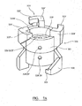
figure 7A illustrates a further specific implementation of the present bioreactor chamber comprising a chamber body with means for releasably coupling two respective end components to form a chamber assembly via interengaging twist-lock formations; -
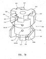
figure 7B illustrates the bioreactor chamber body offigure 7A releasably coupled to two end components by interengaging twist-lock formations to form a chamber assembly. -
Figures 1 to 4 illustrate components of abioreactor chamber assembly 100 according to a specific embodiment of the present invention. Theassembly 100 comprises acap component 110 as shown infigure 1 ,3 and 4 and abase component 120 as shown infigure 1 and2 .Base 120 is configured for mounting upon a substantially flat horizontal surface such as a bench top. Stability for the bioreactor is provided by afoot plate 105 positioned at a lower (second end)region 108 ofbase 120.Foot 105 comprisesprojections 109 extending radially outward frombase 120 relative to a longitudinal axis A centrally bisectingcap 110 andbase 120. -
Base 120 comprises a substantiallycylindrical body 101 having afirst end 106 intended to be positioned uppermost with respect tosecond end 108. Accordingly,base 120 is configured for positioning upon a support surface vialower surface 107. -
Body 101 comprises a first pair ofapertures 103 that provide a through bore into the hollow interior ofbody 101.Body 101 further comprises a second pair ofapertures 104 that also extend through the walls ofbody 101 to the internal chamber of thebioreactor 100.Apertures 103 represent respective gas inlets and outlets andapertures 104 correspond to liquid inlets and outlets. Relative to longitudinal axis A, the gas inlet andoutlet 103 are positioned higher than liquid inlet andoutlet 104 such thatapertures 103 are positioned closest tofirst end 106 whilstapertures 104 are positioned closest tosecond end 108. -
Body 101 comprises substantiallycylindrical chamber walls 126 that define a substantially cylindricalinternal chamber 200 that extends fromsecond end 108 tofirst end 106 atbase 120. - Referring to
figure 1 ,3 and 4 , thecap 110 comprises a substantially cylindricalbasal portion 110B from which threeinterengaging formations 114 protrude in a generally radial direction relative to axis A. Theformations 114 are spaced circumferentially about thebasal portion 1 10B at intervals and are substantially equidistant from one another. Theformations 114 are provided withflange portions 113 that protrude from theformations 114 in a common circumferential direction around thebasal portion 110B. In the arrangement shown the flange portions protrude in a clockwise circumferential direction with respect to the view offigure 1 and4 . - The
flange portions 113 may be considered to be extensions of theformations 114 around thebasal portion 110B, the flange portions being of a smaller thickness in a direction parallel to axis A normal to the radial and circumferential directions of thebasal portion 110B. In the present embodiment, theflange portions 113 also extend a lesser radial distance away from thebasal portion 110B than do theformations 114. - Each
flange 113 comprises a thickness in the longitudinal direction of axis A that decreases in the circumferential direction away fromfoot formations 114. That is, when orientated in normal use, a downward facing surface offlange 113 is perpendicular to axis A whilst anupward facing surface 113S is inclined so as to be aligned transverse to a plane perpendicular to longitudinal axis A. This decreasing wedge shaped profile offlange 113 cooperates with a corresponding wedge shaped flange ofbase component 120, discussed below, to progressively strengthen the fluid tight seal at the internal chamber.Abutment surface 113 S terminates at abuffer surface 114S provided atformations 114. - The
basal portion 110B of thecap 110 has a substantiallycylindrical mating portion 116 extending upwardly therefrom in an axial direction; a cylinder axis C of the mating portion coinciding with a longitudinal axis of thecap 110 and of the chamber assembly. Themating portion 116 bears a mating surface 116M being a radially outer surface thereof. Themating portion 116 is tapered such that a thickness of themating portion 116 decreases in a direction of themating portion 116 away from thebasal portion 110B, themating portion 116 having an outer diameter that reduces with distance from thebasal portion 110B. - Referring to
figures 1 and2 ,base 120 and inparticular body 101 comprises threearms 124 at spaced apart locations around the circumference ofbody 101 and in particularcylindrical walls 126. Eacharm 124 projects away from thebody 101 in a radial direction and comprises aflange portion 123 projecting from an upper edge thereof (with respect to a normal upright orientation of the body 120). Theflange portion 123 projects from the upper edge of eacharm 124 in a substantially circumferential anticlockwise direction. In particular, eachflange 123 extending fromarm 124 comprises acorresponding abutment surface 123S configured toabut surface 113S offace 110. -
Arms 124 are spaced about thebody 101 at locations corresponding to those of theformations 114 of thecap 110. Accordingly, theflanges 123 are configured to cooperate with theflanges 113 to allow thecap 110 andbase 120 to be coupled together. In use, thecap 110 andbase 120 components are presented to one other and slid together such that theformations 114 andarms 124 of therespective components components respective flange portions surfaces flange portion alternative buffer surface 124S ofarm 124 andbuffer surface 114S offormations 114. - As
flange 113 is tapered circumferentially such that it becomes progressively thicker in the axial direction towardsformations 114,base 120 andcap 110 are drawn together in the axial direction as the abutment surfaces 113S, 123S slide in touching contact against one another. According to further embodiments,flange 123 may also comprise a tapering thickness in the circumferential direction about longitudinal axis A. Alternatively,flange 113 may comprise a uniform thickness in the axial direction whilstflange 123 comprises a wedged profile increasing in thickness in the axial direction towardsarm 124. - In some embodiments the
respective flange portions components - An internal surface of the
body 101 is provided with amating surface 126M between theend 106 and ashoulder 129 being a portion of the internal surface of thebody 101 between themating surface 126M and a lower extending inner sidewall ofbody 101 that defines the majority ofinternal chamber 200. The inner sidewall ofchamber 200 is oriented substantially parallel to the cylinder axis C of thebase 120 and is of a diameter smaller than that of themating surface 126M at its upper end in the longitudinal direction. - The
mating surface 126M of thebody 101 is arranged in use to abut the corresponding tapered cylindrical mating portion 116M of thecap 110. A free end of themating portion 116 of thecap 110 is arranged to abut theshoulder 129 of thebase 120. In order to reduce a risk of fluid leakage from theassembly 100 theshoulder 129 is provided with a ridged portion at a location substantially radially midway between opposed circumferential boundaries of theshoulder 129. According to some embodiments, the bioreactor is provided with a ridged portion on the free end of themating portion 116 instead of or in addition to theshoulder 129. - According to the preferred embodiment,
cap component 110 is provided with awindow 118W in anupper surface 117 to allow inspection of the internal chamber. Thewindow 118W may for example be used for visual inspection of the specimen, for example, using a microscope and/or camera arrangement. Alternatively or in addition thewindow 118W may provide a port through which one or more other analytical instruments may inspect the specimen. In the embodiment offigure 1 to 4 thewindow 118W is recessed in asurface 117 of thecap portion 110B being an uppermost region ofcap 110. Thewindow 118W may be integrally formed with thecap 110 or be a separate component connected to thecap 110. In the embodiment offigures 1 to 4 thewindow 118W is integrally formed by moulding, with the window being formed from the same material as the remainder of thecap 110. -
Figure 5 illustrates the assembled bioreactor offigure 1 according to a slightly different embodiment. The method of operation and the majority of the components of the bioreactors offigures 1 to 4 andfigure 5 are largely the same. However, the method of attachment oflid 110 tobase 120 differs slightly. In particular, and referring tofigure 5 ,lid 110 atsurface 500 comprises suitable formations to cooperate with corresponding formations provided at upper external facingsurface 501 ofbody 101. Accordingly,lid 110 is releasably secured tobase 120 via a cooperation offormations lid 110 may be secured tobase 120 via snap and click members, bayonet fittings, push-fit fittings, hook and shoulder fittings and other releasable locking mechanisms operable via a push-fit or press-lock operation in the axial direction. - Additionally and referring to the embodiment of
figure 5 ,window 118W is formed non-integrally withcap 110. In particular,cap 110 comprises a central axially alignedaperture 514. Anannular pocket 513 is recessed intocap 110 and extends radially out fromaperture 514 to receive and retain an outer circumferential edge ofwindow 118W. - The
chamber interior 200 is defined bycylindrical chamber walls 126 ofbase 120 that is enclosed at its upper end bycap 110 and at its lower end bybase 105. A plurality of different sample mounts extend radially inward from theinternal walls 126 ofbase 120. In particular, afirst set 502 of sample mounts are positioned towards anupper region 106 of chamber interior 200 towardscap 110. A second set ofmounts 503 may also be positioned towardsupper region 106 and extend over a greater axial length than first mounts 502. Each respective set of mounts comprises a radially inward facing mountingsurface Surface walls 101 towards the lower region of chamber interior 200 towardsbase 105. Again, these further sets ofmounts inclined surface profile bioreactor assembly 100 is configured to mount a plurality of different sized sample holders including in particular Transwell® and Thincert® mounting systems. Such holders would typically be mounted via their uppermost ends atmounts - Alternatively, a
sample support shelf 507 maybe mounted atlower mountings figure 5 . In use, asample 506 is supported via a suitable substrate orother support structure 506S. - As shown in
figure 5 , gas inlet 103IN is positioned in an upper half in the axial direction throughchamber walls 126. A corresponding gas outlet 103OUT is positioned above inlet 103IN and closer to theupper end 106 in the axial direction. A diameter of the gas inlet and outlet 103IN, 103OUT, is substantially the same. The respective liquid inlet 104IN and outlet 104OUT are positioned in a lower half ofchamber walls 126 and are aligned approximately at the same height or distance frombase 105 relative to longitudinal axis A. According to the embodiment offigure 5 , a diameter of outlet 104OUT is greater than inlet 104IN. Both respective pairs of inlets 103IN, 104IN and outlets 103IN, 104OUT are positioned diametrically opposed to one another such that fluid flow from the respective inlet to the outlet passes through theinternal chamber 200. - In summary, the
present bioreactor 100 allows the inflow of a supply of agas 509 via inlet 103IN. The majority of this gas then flows out ofchamber interior 200 via outlet 103OUT. In addition,reactor 100 allows the inflow of a liquid 510 through inlet 104IN. The liquid flows fromchamber interior 200 out through outlet 104OUT. - In particular, and referring to
figures 5 and6 , a specimen 506 (for example a tissue culture, tissue sample or other biological material) is suspended on thespecimen support 506S. Theflow path 510 of liquid medium is established through theassembly 100 from the liquid inlet 104IN to the liquid outlet 104OUT. The flow rate of liquid through the inlet and outlet aperture 104IN, 104OUT is arranged to maintain a substantially stable liquid level within theassembly 100. Accordingly, a height of a gas-liquid interface 508 above alower surface 516 of theassembly 100 is arranged to remain substantially constant. - In some embodiments this is accomplished by pumping fluid out from the
assembly 100 through the liquid outlet aperture 104OUT at a higher rate than it is pumped into theassembly 100 through the liquid inlet aperture 104IN. It will be appreciated that under such conditions theliquid level 508 will typically not rise above the level of the liquid outlet aperture 104OUT. Accordingly, thechamber assembly 100 may be configured to provide a 'weir' effect, limiting a height to which theliquid level 508 may rise. If the level of the gas-liquid interface 508 in thechamber assembly 100 should rise, for example due to an unexpected influx of liquid or a temporary restriction of the outlet aperture 104OUT or anoutlet hose 606, the level of the gas-liquid interface 508 will fall to and remain stable at the level previously assumed. This can be important when conducting tissue culture experiments since supporting aspecimen 506 at or close to theinterface 508 may be critical to simulating an environment to which a particular tissue is exposed in vivo. According to further specific embodiments,specimen 506 may be suspended or supported so as to be positioned above generally above or mainly above the gas-liquid interface 508. Accordingly, liquid flowing throughchamber 200 is 'drawn-up' intospecimen 506 by the action of the liquid surface tension. - As indicated, the liquid outlet aperture 104OUT is of a larger diameter than the liquid inlet aperture 104IN and the apparatus of which the
assembly 100 forms part is arranged to pump liquid out from theassembly 100 at a higher rate than that at which liquid is pumped into theassembly 100. Consequently, the apparatus may pump gas out through the liquid outlet aperture 104OUT in addition to liquid. This feature has the advantage that a flow path ofgas 511 through theassembly 100 may be modified and controlled by controlling the relative rates at which liquid is pumped into the chamber through the inlet aperture 104IN and fluid is pumped out through the liquid outlet aperture 104OUT. Accordingly, gas may be drawn towards and out through the liquid outlet aperture 104OUT in addition to or instead of the gas outlet aperture 103OUT. - Referring to
figure 6 , aperistaltic pump 604 is connected to inlet 104IN viatubing 608 and outlet 104OUT bytubing Pump 604 is employed to pump liquid intochamber interior 200 via inlet 104IN. In particular, chamber interior is connected to pump 604 via two sides: a pre chamber side P1 and post chamber side P2. As the flow rate is intended to be greater at the post chamber side, the flow at P2 is greater than the flow at P1. This can be controlled using asingle pump 604 at a single speed such that the flow rate through the inlet and outlet tubing is different and determined by the relative diameter of tubing used. Alternatively and according to further embodiments twoseparate pumps 604 may be provided at the pre and post chamber side with manifold tubing of the same internal diameter but with a pump speed greater at the post chamber side (P2). The liquid network or circuit is completed as the liquid phaseperistaltic pump 604 is coupled to aliquid reservoir 605 viasuitable conduits 610. - In some embodiments the
fluid conduits fluid conduits - However, according to the preferred embodiment the first P1 and second P2 pumps are provided by a
single pump 604 having first and secondfluid conduits 609 around a common roller assembly. Thus as the rollers rotate, fluid is simultaneously pumped through bothconduits 609. - In the embodiment of
figure 6 theconduits pump 604 rotates at a given rotational speed. - It is to be understood that in some alternative embodiments the
conduits conduits pump 604 is arranged to pump fluid through more than twoconduits - The present apparatus allows a flow path of gas within the
assembly 100 to be controlled so that it flows close to or in direct contact with a specimen which is particularly advantageous in experiments where exposure of tissue to gas is of particular interest or importance. Examples of such experiments include those where the specimen comprises lung tissue and/or one or more other tissues associated with a respiratory system. Experiments in respect of other biological samples may also be enhanced when performed using embodiments of the present invention. - Embodiments of the present invention provide apparatus in which experiments may be performed with
specimen 506 held at or near the gas-liquid interface 508 in which a flow of liquid and/or gas is maintained over the specimen. Theinterface 508 may be maintained at a prescribed height withinchamber 200 in a reliable manner. As described above, in some arrangements the height of theinterface 508 is arranged to be corrected automatically by the apparatus in the event the height rises above the prescribed height. - Accordingly, to simulate exposure to a flow of gas at biological martial site, the present assembly is configured for connection to a gas phase network in combination with the liquid phase network as described. The gaseous fluid is circulated through
chamber interior 200 by connecting inlet 103IN and outlet 103OUT to asuitable gas reservoir 600. A second or furtherperistaltic pump 601 is positioned betweengas reservoir 600 and gas outlet 103OUT so as to draw the flow ofgas 513 out ofchamber interior 200. This in turn induces the flow ofgas 509 intochamber interior 200. As will be appreciated, thepresent assembly 100 is suitable for a gas to be supplied directly to thechamber interior 200 under pressure with or without apump 601. Where apump 601 is included, this may be positioned at the inlet or outlet side of the chamber relative to the position within the network of thegas reservoir 600. - In some embodiments the apparatus is arranged so as to prevent the level of the
interface 508 falling below that of the liquid outlet aperture 104OUT even if a flow ofliquid 510 into the assembly is terminated. In some embodiments the liquid outlet aperture 104OUT is provided such that a lower level of the aperture corresponds to a lowest acceptable level of fluid in the assembly. - Other numbers of inlet and outlet apertures allowing the flow of fluid into or out from the
assembly 100 than those of the embodiments illustrated are also useful. In some arrangements achamber assembly 100 is provided with three and in some arrangements more than four apertures for allowing a flow of fluid into or out from theassembly 100. - The present invention provides a
chamber assembly 100 allowing relative rapid and convenient assembly and disassembly. In some embodiments, aspecimen 506 may be mounted on thespecimen support 506S and theassembly 100 assembled in a rapid and reliable manner allowing a sample of biological material comprised by thespecimen 506 to continue to function substantially uninterrupted whilst theassembly 100 is assembled and a supply ofliquid 510 and/orgas 509 to theassembly 100 is established. -
Figure 7A and7B illustrate abioreactor chamber assembly 300 according to a further embodiment of the present invention. As will be noted, the interengaging formations offigure 7A and7B correspond to the interengaging formations described with reference tofigures 1 to 4 . The features of the embodiment offigures 7A and7B are indicated with like reference numerals prefixed withnumeral 3 instead of 1.Figure 7A shows abody component 320 only of the assembly whilstfigure 7B shows thebody component 320 having base (or end)components 310, 310' coupled to opposite ends thereof. Thebase components 310, 310' are substantially identical to one another and to thecap component 110 of the embodiment offigure 2 . Thebase components 310, 310' are arranged to be interchangeable in the embodiment shown although other arrangements are also useful, particularly where an internal shape of the upper base component 310' is required to be different from that of thelower base component 310. - The
body 320 hasfeet 324, 324' havingtongue portions 323, 323' at opposed ends thereof definingrespective jaws 325, 325' that are configured in a substantially identical manner to one another and to theformations 124 of the assemblies offigures 1 to 5 . Thejaws 325, 325' of thebody component 320 are arranged to receive corresponding tongue portions 312,312' of thebase components 310, 310' when theassembly 300 is assembled. - The body component has two pairs of apertures formed therein to allow fluid to flow through the internal volume of the body component when the
base components 310, 310' are coupled to it. A gas inlet aperture 328IN' and a gas outlet aperture 328OUT' are provided at diametrically opposed locations of the body portion 320B in an upper portion of thebody 320 as with the embodiment offigures 1 to 5 . - A liquid inlet aperture 328IN and a liquid outlet aperture 328OUT are provided at corresponding locations below the gas inlet and outlet apertures 328IN', 328OUT'. The liquid inlet and outlet apertures 328IN, 328OUT are provided at substantially the same height. In the embodiment of
figure 7A and7B the liquid outlet aperture is arranged to have a larger diameter than the liquid inlet aperture 328IN. Other positions of the apertures 328IN, 328OUT, 328IN', 328OUT' about a circumference of thebody 320 are also useful. - In some embodiments the liquid outlet aperture 328OUT is of substantially the same cross-sectional area as the liquid inlet aperture 328IN. In the present embodiment they are of substantially the same diameter. In some embodiments the liquid outlet aperture 328OUT has a diameter smaller than that of the liquid inlet aperture 328IN.
- In the embodiment of
figure 7A and7B the gas inlet and outlet apertures 328IN', 328OUT' are substantially the same diameter. In some alternative embodiments the gas inlet aperture 328IN' is smaller than the gas outlet aperture 328OUT' whilst in some further embodiments the gas inlet aperture 328IN' is larger than the gas outlet aperture 328OUT'. Whilst the inlet and outlets have been described above with reference to one handling a flow of liquid and the other handling a flow of gas, it is to be understood that in some arrangements both may be used for liquid or both may be used for gas. - Referring to the embodiment of
figures 7A and7B , in some arrangements the gas inlet aperture 328IN' may be used to deliver liquid to theassembly 300 in addition to or instead of the liquid inlet aperture 328IN. The gas inlet aperture 328IN' may be used to deliver liquid continuously, or intermittently. In some arrangements the gas inlet aperture 328IN' may be used to deliver both liquid and gas substantially simultaneously.
Claims (15)
- A bioreactor chamber assembly comprising:at least a base (120) and a cap (110) configured to be coupled together to define a chamber body having a wall (126) that defines an internal chamber (200) to accommodate a biological sample;characterised in that:the base (120) and cap (110) each comprising a plurality of respective interengaging flanges (113, 123) to allow the base (120) and cap (110) to be releasably coupled and locked together axially relative to a longitudinal axis (A) bisecting the base (120) and cap (110) by rotation of at least one of the base (120) and cap (110) about the longitudinal axis (A);the base (120) and cap (110) each further comprising a respective sealing surface (116M, 126M) that may be drawn and mated together axially via an interference fit arrangement by said rotation to provide a fluid tight seal when the base (120) and cap (110) are locked together axially;a liquid inlet (104IN) to allow a liquid to flow into the internal chamber (200);a liquid outlet (104OUT) to allow a liquid to flow out from the internal chamber (200) and being separate to the liquid inlet (104IN);a gas inlet (103IN) to allow a gas to flow into the internal chamber (200); anda gas outlet (103 OUT) to allow a gas to flow out from the internal chamber (200) and being separate to the gas inlet (103IN);wherein the liquid inlet (104IN) and outlet (104OUT) are positioned at an axial height lower than an axial height of the gas inlet (103IN) and outlet (103OUT) relative to a longitudinal axis (A) of the chamber assembly extending through the base (120) and cap (110) such that a gas-liquid interface may be created within the internal chamber between the liquid and the gas;wherein the liquid inlet (104IN) and outlet (104OUT) are positioned at substantially the same axial height at the chamber wall (126) to assist maintaining the axial position of the gas-liquid interface;the chamber assembly further comprising at least one sample support mount (504) provided at a region of the chamber wall (126) to mount the biological sample at a position relative to the longitudinal axial (A) such that the biological sample is maintainable in contact with the gas-liquid interface.
- The assembly as claimed in claim 1 wherein the base (120) comprises a foot portion (105) to support the chamber body in an upright orientation when standing upon a support structure.
- The assembly as claimed in claim 1 or 2 wherein the cap (110) comprises a window (118W) to allow the internal chamber (200) to be viewed externally.
- The assembly as claimed in any preceding claim wherein the interengaging flanges (113, 123) project radially outward from at least the base (120) and cap (110) to allow the base (120) and cap (110) to be releasably coupled together axially.
- The assembly as claimed in claim 4 wherein the respective flanges (113, 123) extend in a circumferential direction around the base (120) and cap (110) wherein respective flange (113, 123) of the base (120) and cap (110) are configured to slide over one another to couple the base (120) and cap (110) and prevent axial separation.
- The assembly as claimed in claim 5 wherein each flange (113, 123) of the base (120) and cap (110) comprises a respective abutment surfaces (113S, 123S) extending in the circumferential direction around the longitudinal axis (A) and configured to cooperatively abut one another when the base (120) and cap (110) are coupled together by rotation about the longitudinal axis (A);
wherein at least one of the abutment surfaces (113S, 123S) extends in a circumferential direction at an angle transverse to a plane perpendicular to the longitudinal axis (A) such that as the flanges (113, 123) of the base (120) and cap (110) are slid over one another the base (120) and cap (110) are drawn together axially. - The assembly as claimed in any preceding claim wherein the gas inlet (103IN) and outlet (103OUT) are positioned at substantially different axial height positions at the chamber wall (126) relative to the longitudinal axis (A).
- The assembly as claimed in any preceding claim wherein a cross sectional size of the liquid outlet (104OUT) is greater than a cross sectional size of the liquid inlet (104IN) at the chamber wall (126).
- The assembly as claimed in any preceding claim comprising a plurality of sample support mounts (502, 503, 504, 505) provided at different axial positions at the internal side of the chamber walls (126) relative to the longitudinal axis (A).
- The assembly as claimed in claim 9 wherein at least one of the sample support mounts (502, 503, 504, 505) is positioned at an upper region of the chamber assembly, when the assembly is orientated in normal use.
- The assembly as claimed in claims 9 or 10 wherein at least one sample support mount (504, 505) is positioned towards a lower region of the assembly when the assembly is orientated in normal use.
- Bioreactor apparatus comprising:a chamber assembly as claimed in any preceding claim;a first fluid network (606,607,608) coupled in fluid communication to the liquid inlet (104IN) and outlet (104OUT), the first fluid network (606, 607, 608) comprising a liquid source (605) and a pump (604) to supply liquid to the internal chamber (200) from the liquid source (605) via the liquid inlet (104IN) and to exit the internal chamber (200) via the liquid outlet (104OUT).
- The apparatus as claimed in claim 12 further comprising a second fluid network (602,603) coupled in fluid communication to the gas inlet (103IN) and outlet (103OUT, the second fluid network (602, 603) comprising a gas source (600) such that gas may be supplied to the internal chamber (200) via the gas inlet (103IN) and to exit the internal chamber (200) via the gas outlet (103OUT).
- The apparatus as claimed in claim 13 further comprising a second pump (601) to supply gas to the internal chamber (200) via the gas inlet (103IN) and to allow gas to exit the internal chamber (200) via the gas outlet (103OUT).
- A method of creating and maintaining an environment to support a biological species, the method comprising:providing a chamber body having walls (126) that define an internal chamber (200) to accommodate the biological species, the chamber body comprising at least a base (120) and a cap (110) configured to be coupled together to define the chamber body;
characterised in that:the base (120) and cap (110) each comprising a plurality of respective interengaging flanges (113, 123) to allow the base (120) and cap (110) to be releasably coupled together axially relative to a longitudinal axis (A) bisecting the base (120) and cap (110) by rotation of at least one of the base (120) and cap (110) about the longitudinal axis (A), the base (120) and cap (110) each further comprising a respective sealing surface (116M, 126M) that may be drawn and mated together axially via an interference fit arrangement by said rotation to provide a fluid tight seal when the base (120) and cap (110) are coupled together axially;providing a flow of a liquid through the internal chamber (200) in contact with biological species via a liquid inlet (104IN) and a separate liquid outlet (104OUT) at the chamber body, the liquid inlet (104IN) and outlet (104OUT) being positioned at substantially the same axial height at the chamber wall (126) relative to a longitudinal axis (A) of the chamber assembly extending through the base (120) and cap (110);providing a flow of a gas through the internal chamber (200) in contact with biological species via a gas inlet (103IN) and a separate gas outlet (103OUT) at the chamber body;creating a gas-liquid interface within the internal chamber (200) as the liquid inlet (104IN) and outlet (104OUT) are positioned at an axial height lower than an axial height of the gas inlet (103IN) and outlet (103OUT) relative to the longitudinal axis (A);mounting the biological species at a position relative to the longitudinal axial (A) such that the biological sample is maintained at a region of the gas-liquid interface via at least one sample support mount (504) provided at a region of the chamber wall (126);wherein the axial position of the liquid inlet (104IN) and outlet (104OUT) assists with maintaining the position of the gas-liquid interface within the internal chamber (200) relative to the longitudinal axis (A).
Applications Claiming Priority (2)
| Application Number | Priority Date | Filing Date | Title |
|---|---|---|---|
| GBGB1108165.0A GB201108165D0 (en) | 2011-05-16 | 2011-05-16 | Bioreactor chamber and method |
| PCT/GB2012/050961 WO2012156683A1 (en) | 2011-05-16 | 2012-05-03 | Bioreactor chamber |
Publications (2)
| Publication Number | Publication Date |
|---|---|
| EP2726596A1 EP2726596A1 (en) | 2014-05-07 |
| EP2726596B1 true EP2726596B1 (en) | 2015-10-14 |
Family
ID=44260594
Family Applications (1)
| Application Number | Title | Priority Date | Filing Date |
|---|---|---|---|
| EP12720563.1A Not-in-force EP2726596B1 (en) | 2011-05-16 | 2012-05-03 | Bioreactor chamber |
Country Status (10)
| Country | Link |
|---|---|
| US (1) | US20140127798A1 (en) |
| EP (1) | EP2726596B1 (en) |
| BR (1) | BR112013029496A2 (en) |
| CA (1) | CA2836132A1 (en) |
| CL (1) | CL2013003291A1 (en) |
| CR (1) | CR20130586A (en) |
| CU (1) | CU20130151A7 (en) |
| GB (1) | GB201108165D0 (en) |
| MX (1) | MX2013013458A (en) |
| WO (1) | WO2012156683A1 (en) |
Families Citing this family (3)
| Publication number | Priority date | Publication date | Assignee | Title |
|---|---|---|---|---|
| US20170240854A1 (en) * | 2014-09-23 | 2017-08-24 | Nanyang Technological University | A bioreactor module, a bioreactor system and methods for thick tissue seeding and cultivation in an hirearchical organization and physiological mimiking conditions |
| US11287358B1 (en) | 2016-04-14 | 2022-03-29 | Triad National Security, Llc | Microfluidic aspirator and multi-purpose flow sensor and methods of making and using the same |
| US10408821B2 (en) * | 2016-04-14 | 2019-09-10 | Triad National Security, Llc | Microfluidic aspirator and methods of making and using the same |
Family Cites Families (10)
| Publication number | Priority date | Publication date | Assignee | Title |
|---|---|---|---|---|
| US3704802A (en) * | 1971-06-30 | 1972-12-05 | Robert S Schultz | Child resistant safety cap closure assembly for a container |
| DE3628930A1 (en) * | 1986-08-26 | 1988-05-05 | Greiner & Soehne C A | CONTAMINATION-SAFE CAP, IN PARTICULAR SCREW CAP FOR CELL CULTURE BOTTLES |
| FR2803852B1 (en) * | 2000-01-17 | 2004-11-05 | Farzin Sarem | CELL AND TISSUE CULTURE DEVICE WITH CONTROLLED CULTURE FLUID CIRCULATION |
| ITPI20040046A1 (en) | 2004-06-18 | 2004-09-18 | Univ Pisa | BIOREACTOR FOR THE STUDY OF THE EFFECTS ON THE CELL ACTIVITIES OF IMPOSED STIMULES |
| US7022518B1 (en) * | 2005-01-31 | 2006-04-04 | Glen Feye | Apparatus and method for co-culturing of cells |
| US8101387B2 (en) * | 2007-06-08 | 2012-01-24 | Coskata, Inc. | Process to sequence bioreactor modules for serial gas flow and uniform gas velocity |
| GB2470227A (en) | 2009-05-15 | 2010-11-17 | Kirkstall Ltd | Multi-cavity bioreactor chamber |
| US8735144B2 (en) | 2008-08-01 | 2014-05-27 | Kirstall Limited | Bioreactor chamber |
| US20110207175A1 (en) | 2008-10-06 | 2011-08-25 | Mc2 Cell Aps | Multi-culture bioreactor system |
| US9321988B2 (en) * | 2009-06-18 | 2016-04-26 | Illinois Tool Works Inc. | Gas and liquid tissue culture interface |
-
2011
- 2011-05-16 GB GBGB1108165.0A patent/GB201108165D0/en not_active Ceased
-
2012
- 2012-05-03 CA CA2836132A patent/CA2836132A1/en not_active Abandoned
- 2012-05-03 BR BR112013029496A patent/BR112013029496A2/en not_active IP Right Cessation
- 2012-05-03 US US14/118,265 patent/US20140127798A1/en not_active Abandoned
- 2012-05-03 MX MX2013013458A patent/MX2013013458A/en not_active Application Discontinuation
- 2012-05-03 EP EP12720563.1A patent/EP2726596B1/en not_active Not-in-force
- 2012-05-03 WO PCT/GB2012/050961 patent/WO2012156683A1/en not_active Ceased
-
2013
- 2013-11-12 CR CR20130586A patent/CR20130586A/en unknown
- 2013-11-15 CL CL2013003291A patent/CL2013003291A1/en unknown
- 2013-11-18 CU CU2013000151A patent/CU20130151A7/en unknown
Also Published As
| Publication number | Publication date |
|---|---|
| CU20130151A7 (en) | 2014-04-24 |
| MX2013013458A (en) | 2014-08-18 |
| EP2726596A1 (en) | 2014-05-07 |
| CA2836132A1 (en) | 2012-11-22 |
| US20140127798A1 (en) | 2014-05-08 |
| WO2012156683A1 (en) | 2012-11-22 |
| BR112013029496A2 (en) | 2017-01-24 |
| CL2013003291A1 (en) | 2014-08-08 |
| CR20130586A (en) | 2014-05-20 |
| GB201108165D0 (en) | 2011-06-29 |
Similar Documents
| Publication | Publication Date | Title |
|---|---|---|
| US10323221B2 (en) | Device for controlled apical flow in cell culture inserts | |
| US10519409B2 (en) | Shaft-mounted fluid transfer assembly for a disposable bioreactor | |
| US5153131A (en) | High aspect reactor vessel and method of use | |
| CN111801410A (en) | Bioreactors and Related Methods | |
| EP2411501B1 (en) | Apparatus for cell or tissue culture | |
| Giulitti et al. | Optimal periodic perfusion strategy for robust long-term microfluidic cell culture | |
| CN115044471B (en) | Bioreactor | |
| PT1451290E (en) | A unit and a process for carrying out high cell density fermentation | |
| US20140127798A1 (en) | Bioreactor chamber | |
| US9243220B2 (en) | Bioreactor chamber | |
| US10745660B2 (en) | System for incubating microfluidic droplets and method for producing homogeneous incubation conditions in a droplet incubation unit | |
| Raimes et al. | Transfection in perfused microfluidic cell culture devices: A case study | |
| US20180291325A1 (en) | In vitro pharmacokinetic-pharmacodynamic device | |
| CN113396010B (en) | Impeller and ejector assemblies for biological treatment systems | |
| CN116836790A (en) | Organoid-on-a-chip device for high-throughput drug testing and methods of use | |
| EP2710110B1 (en) | Bioreactor chamber | |
| US20230221300A1 (en) | Methods and devices for cell based assays | |
| EP3831922A1 (en) | Roller tube culture system | |
| US20260117159A1 (en) | Cell Suspension Culture Device Provided With Flow Diverter | |
| CN216236980U (en) | Aeration equipment is used in fermentation of living fungus of benefit | |
| US12188038B2 (en) | Methods, devices and systems for enhanced transduction efficiency | |
| CN115011475A (en) | An in vitro three-dimensional cell or organoid culture device and its culture system | |
| CN205941271U (en) | Rectilinear release pond of two stirrings | |
| HK40072014B (en) | Bioreactor | |
| HK40108453A (en) | Impeller and sparger assemblies for a bioprocessing system |
Legal Events
| Date | Code | Title | Description |
|---|---|---|---|
| PUAI | Public reference made under article 153(3) epc to a published international application that has entered the european phase |
Free format text: ORIGINAL CODE: 0009012 |
|
| 17P | Request for examination filed |
Effective date: 20131129 |
|
| AK | Designated contracting states |
Kind code of ref document: A1 Designated state(s): AL AT BE BG CH CY CZ DE DK EE ES FI FR GB GR HR HU IE IS IT LI LT LU LV MC MK MT NL NO PL PT RO RS SE SI SK SM TR |
|
| DAX | Request for extension of the european patent (deleted) | ||
| GRAP | Despatch of communication of intention to grant a patent |
Free format text: ORIGINAL CODE: EPIDOSNIGR1 |
|
| INTG | Intention to grant announced |
Effective date: 20150318 |
|
| INTG | Intention to grant announced |
Effective date: 20150323 |
|
| REG | Reference to a national code |
Ref country code: DE Ref legal event code: R079 Ref document number: 602012011548 Country of ref document: DE Free format text: PREVIOUS MAIN CLASS: C12M0003000000 Ipc: C12M0001000000 |
|
| GRAP | Despatch of communication of intention to grant a patent |
Free format text: ORIGINAL CODE: EPIDOSNIGR1 |
|
| RIC1 | Information provided on ipc code assigned before grant |
Ipc: C12M 1/24 20060101ALI20150430BHEP Ipc: C12M 1/34 20060101ALI20150430BHEP Ipc: C12M 3/00 20060101ALI20150430BHEP Ipc: C12M 1/00 20060101AFI20150430BHEP |
|
| INTG | Intention to grant announced |
Effective date: 20150515 |
|
| GRAS | Grant fee paid |
Free format text: ORIGINAL CODE: EPIDOSNIGR3 |
|
| GRAA | (expected) grant |
Free format text: ORIGINAL CODE: 0009210 |
|
| AK | Designated contracting states |
Kind code of ref document: B1 Designated state(s): AL AT BE BG CH CY CZ DE DK EE ES FI FR GB GR HR HU IE IS IT LI LT LU LV MC MK MT NL NO PL PT RO RS SE SI SK SM TR |
|
| REG | Reference to a national code |
Ref country code: GB Ref legal event code: FG4D |
|
| REG | Reference to a national code |
Ref country code: AT Ref legal event code: REF Ref document number: 755092 Country of ref document: AT Kind code of ref document: T Effective date: 20151015 Ref country code: CH Ref legal event code: EP |
|
| REG | Reference to a national code |
Ref country code: IE Ref legal event code: FG4D |
|
| REG | Reference to a national code |
Ref country code: DE Ref legal event code: R096 Ref document number: 602012011548 Country of ref document: DE |
|
| REG | Reference to a national code |
Ref country code: NL Ref legal event code: MP Effective date: 20151014 |
|
| REG | Reference to a national code |
Ref country code: LT Ref legal event code: MG4D |
|
| REG | Reference to a national code |
Ref country code: AT Ref legal event code: MK05 Ref document number: 755092 Country of ref document: AT Kind code of ref document: T Effective date: 20151014 |
|
| PG25 | Lapsed in a contracting state [announced via postgrant information from national office to epo] |
Ref country code: IS Free format text: LAPSE BECAUSE OF FAILURE TO SUBMIT A TRANSLATION OF THE DESCRIPTION OR TO PAY THE FEE WITHIN THE PRESCRIBED TIME-LIMIT Effective date: 20160214 Ref country code: NL Free format text: LAPSE BECAUSE OF FAILURE TO SUBMIT A TRANSLATION OF THE DESCRIPTION OR TO PAY THE FEE WITHIN THE PRESCRIBED TIME-LIMIT Effective date: 20151014 Ref country code: ES Free format text: LAPSE BECAUSE OF FAILURE TO SUBMIT A TRANSLATION OF THE DESCRIPTION OR TO PAY THE FEE WITHIN THE PRESCRIBED TIME-LIMIT Effective date: 20151014 Ref country code: HR Free format text: LAPSE BECAUSE OF FAILURE TO SUBMIT A TRANSLATION OF THE DESCRIPTION OR TO PAY THE FEE WITHIN THE PRESCRIBED TIME-LIMIT Effective date: 20151014 Ref country code: LT Free format text: LAPSE BECAUSE OF FAILURE TO SUBMIT A TRANSLATION OF THE DESCRIPTION OR TO PAY THE FEE WITHIN THE PRESCRIBED TIME-LIMIT Effective date: 20151014 Ref country code: NO Free format text: LAPSE BECAUSE OF FAILURE TO SUBMIT A TRANSLATION OF THE DESCRIPTION OR TO PAY THE FEE WITHIN THE PRESCRIBED TIME-LIMIT Effective date: 20160114 |
|
| REG | Reference to a national code |
Ref country code: FR Ref legal event code: PLFP Year of fee payment: 5 |
|
| PG25 | Lapsed in a contracting state [announced via postgrant information from national office to epo] |
Ref country code: AT Free format text: LAPSE BECAUSE OF FAILURE TO SUBMIT A TRANSLATION OF THE DESCRIPTION OR TO PAY THE FEE WITHIN THE PRESCRIBED TIME-LIMIT Effective date: 20151014 Ref country code: LV Free format text: LAPSE BECAUSE OF FAILURE TO SUBMIT A TRANSLATION OF THE DESCRIPTION OR TO PAY THE FEE WITHIN THE PRESCRIBED TIME-LIMIT Effective date: 20151014 Ref country code: RS Free format text: LAPSE BECAUSE OF FAILURE TO SUBMIT A TRANSLATION OF THE DESCRIPTION OR TO PAY THE FEE WITHIN THE PRESCRIBED TIME-LIMIT Effective date: 20151014 Ref country code: SE Free format text: LAPSE BECAUSE OF FAILURE TO SUBMIT A TRANSLATION OF THE DESCRIPTION OR TO PAY THE FEE WITHIN THE PRESCRIBED TIME-LIMIT Effective date: 20151014 Ref country code: FI Free format text: LAPSE BECAUSE OF FAILURE TO SUBMIT A TRANSLATION OF THE DESCRIPTION OR TO PAY THE FEE WITHIN THE PRESCRIBED TIME-LIMIT Effective date: 20151014 Ref country code: GR Free format text: LAPSE BECAUSE OF FAILURE TO SUBMIT A TRANSLATION OF THE DESCRIPTION OR TO PAY THE FEE WITHIN THE PRESCRIBED TIME-LIMIT Effective date: 20160115 Ref country code: PT Free format text: LAPSE BECAUSE OF FAILURE TO SUBMIT A TRANSLATION OF THE DESCRIPTION OR TO PAY THE FEE WITHIN THE PRESCRIBED TIME-LIMIT Effective date: 20160215 Ref country code: PL Free format text: LAPSE BECAUSE OF FAILURE TO SUBMIT A TRANSLATION OF THE DESCRIPTION OR TO PAY THE FEE WITHIN THE PRESCRIBED TIME-LIMIT Effective date: 20151014 |
|
| REG | Reference to a national code |
Ref country code: DE Ref legal event code: R097 Ref document number: 602012011548 Country of ref document: DE |
|
| PG25 | Lapsed in a contracting state [announced via postgrant information from national office to epo] |
Ref country code: CZ Free format text: LAPSE BECAUSE OF FAILURE TO SUBMIT A TRANSLATION OF THE DESCRIPTION OR TO PAY THE FEE WITHIN THE PRESCRIBED TIME-LIMIT Effective date: 20151014 |
|
| PLBE | No opposition filed within time limit |
Free format text: ORIGINAL CODE: 0009261 |
|
| STAA | Information on the status of an ep patent application or granted ep patent |
Free format text: STATUS: NO OPPOSITION FILED WITHIN TIME LIMIT |
|
| PG25 | Lapsed in a contracting state [announced via postgrant information from national office to epo] |
Ref country code: DK Free format text: LAPSE BECAUSE OF FAILURE TO SUBMIT A TRANSLATION OF THE DESCRIPTION OR TO PAY THE FEE WITHIN THE PRESCRIBED TIME-LIMIT Effective date: 20151014 Ref country code: BE Free format text: LAPSE BECAUSE OF NON-PAYMENT OF DUE FEES Effective date: 20160531 Ref country code: SM Free format text: LAPSE BECAUSE OF FAILURE TO SUBMIT A TRANSLATION OF THE DESCRIPTION OR TO PAY THE FEE WITHIN THE PRESCRIBED TIME-LIMIT Effective date: 20151014 Ref country code: RO Free format text: LAPSE BECAUSE OF FAILURE TO SUBMIT A TRANSLATION OF THE DESCRIPTION OR TO PAY THE FEE WITHIN THE PRESCRIBED TIME-LIMIT Effective date: 20151014 Ref country code: EE Free format text: LAPSE BECAUSE OF FAILURE TO SUBMIT A TRANSLATION OF THE DESCRIPTION OR TO PAY THE FEE WITHIN THE PRESCRIBED TIME-LIMIT Effective date: 20151014 Ref country code: SK Free format text: LAPSE BECAUSE OF FAILURE TO SUBMIT A TRANSLATION OF THE DESCRIPTION OR TO PAY THE FEE WITHIN THE PRESCRIBED TIME-LIMIT Effective date: 20151014 |
|
| 26N | No opposition filed |
Effective date: 20160715 |
|
| PG25 | Lapsed in a contracting state [announced via postgrant information from national office to epo] |
Ref country code: SI Free format text: LAPSE BECAUSE OF FAILURE TO SUBMIT A TRANSLATION OF THE DESCRIPTION OR TO PAY THE FEE WITHIN THE PRESCRIBED TIME-LIMIT Effective date: 20151014 |
|
| PG25 | Lapsed in a contracting state [announced via postgrant information from national office to epo] |
Ref country code: LU Free format text: LAPSE BECAUSE OF FAILURE TO SUBMIT A TRANSLATION OF THE DESCRIPTION OR TO PAY THE FEE WITHIN THE PRESCRIBED TIME-LIMIT Effective date: 20160503 Ref country code: BE Free format text: LAPSE BECAUSE OF FAILURE TO SUBMIT A TRANSLATION OF THE DESCRIPTION OR TO PAY THE FEE WITHIN THE PRESCRIBED TIME-LIMIT Effective date: 20151014 |
|
| REG | Reference to a national code |
Ref country code: CH Ref legal event code: PL |
|
| PG25 | Lapsed in a contracting state [announced via postgrant information from national office to epo] |
Ref country code: CH Free format text: LAPSE BECAUSE OF NON-PAYMENT OF DUE FEES Effective date: 20160531 Ref country code: LI Free format text: LAPSE BECAUSE OF NON-PAYMENT OF DUE FEES Effective date: 20160531 |
|
| REG | Reference to a national code |
Ref country code: IE Ref legal event code: MM4A |
|
| REG | Reference to a national code |
Ref country code: FR Ref legal event code: PLFP Year of fee payment: 6 |
|
| PG25 | Lapsed in a contracting state [announced via postgrant information from national office to epo] |
Ref country code: IE Free format text: LAPSE BECAUSE OF NON-PAYMENT OF DUE FEES Effective date: 20160503 |
|
| REG | Reference to a national code |
Ref country code: FR Ref legal event code: PLFP Year of fee payment: 7 |
|
| PG25 | Lapsed in a contracting state [announced via postgrant information from national office to epo] |
Ref country code: HU Free format text: LAPSE BECAUSE OF FAILURE TO SUBMIT A TRANSLATION OF THE DESCRIPTION OR TO PAY THE FEE WITHIN THE PRESCRIBED TIME-LIMIT; INVALID AB INITIO Effective date: 20120503 |
|
| PG25 | Lapsed in a contracting state [announced via postgrant information from national office to epo] |
Ref country code: MT Free format text: LAPSE BECAUSE OF NON-PAYMENT OF DUE FEES Effective date: 20160531 Ref country code: CY Free format text: LAPSE BECAUSE OF FAILURE TO SUBMIT A TRANSLATION OF THE DESCRIPTION OR TO PAY THE FEE WITHIN THE PRESCRIBED TIME-LIMIT Effective date: 20151014 Ref country code: MK Free format text: LAPSE BECAUSE OF FAILURE TO SUBMIT A TRANSLATION OF THE DESCRIPTION OR TO PAY THE FEE WITHIN THE PRESCRIBED TIME-LIMIT Effective date: 20151014 Ref country code: MC Free format text: LAPSE BECAUSE OF FAILURE TO SUBMIT A TRANSLATION OF THE DESCRIPTION OR TO PAY THE FEE WITHIN THE PRESCRIBED TIME-LIMIT Effective date: 20151014 |
|
| PG25 | Lapsed in a contracting state [announced via postgrant information from national office to epo] |
Ref country code: BG Free format text: LAPSE BECAUSE OF FAILURE TO SUBMIT A TRANSLATION OF THE DESCRIPTION OR TO PAY THE FEE WITHIN THE PRESCRIBED TIME-LIMIT Effective date: 20151014 |
|
| PG25 | Lapsed in a contracting state [announced via postgrant information from national office to epo] |
Ref country code: TR Free format text: LAPSE BECAUSE OF FAILURE TO SUBMIT A TRANSLATION OF THE DESCRIPTION OR TO PAY THE FEE WITHIN THE PRESCRIBED TIME-LIMIT Effective date: 20151014 Ref country code: AL Free format text: LAPSE BECAUSE OF FAILURE TO SUBMIT A TRANSLATION OF THE DESCRIPTION OR TO PAY THE FEE WITHIN THE PRESCRIBED TIME-LIMIT Effective date: 20151014 |
|
| PGFP | Annual fee paid to national office [announced via postgrant information from national office to epo] |
Ref country code: DE Payment date: 20210527 Year of fee payment: 10 Ref country code: IT Payment date: 20210524 Year of fee payment: 10 Ref country code: FR Payment date: 20210525 Year of fee payment: 10 |
|
| PGFP | Annual fee paid to national office [announced via postgrant information from national office to epo] |
Ref country code: GB Payment date: 20210527 Year of fee payment: 10 |
|
| REG | Reference to a national code |
Ref country code: DE Ref legal event code: R119 Ref document number: 602012011548 Country of ref document: DE |
|
| GBPC | Gb: european patent ceased through non-payment of renewal fee |
Effective date: 20220503 |
|
| PG25 | Lapsed in a contracting state [announced via postgrant information from national office to epo] |
Ref country code: FR Free format text: LAPSE BECAUSE OF NON-PAYMENT OF DUE FEES Effective date: 20220531 |
|
| PG25 | Lapsed in a contracting state [announced via postgrant information from national office to epo] |
Ref country code: GB Free format text: LAPSE BECAUSE OF NON-PAYMENT OF DUE FEES Effective date: 20220503 Ref country code: DE Free format text: LAPSE BECAUSE OF NON-PAYMENT OF DUE FEES Effective date: 20221201 |
|
| PG25 | Lapsed in a contracting state [announced via postgrant information from national office to epo] |
Ref country code: IT Free format text: LAPSE BECAUSE OF NON-PAYMENT OF DUE FEES Effective date: 20220503 |