EP2725864A2 - Radio communication device, method for controlling radio communication, and radio communication system - Google Patents
Radio communication device, method for controlling radio communication, and radio communication system Download PDFInfo
- Publication number
- EP2725864A2 EP2725864A2 EP20130187716 EP13187716A EP2725864A2 EP 2725864 A2 EP2725864 A2 EP 2725864A2 EP 20130187716 EP20130187716 EP 20130187716 EP 13187716 A EP13187716 A EP 13187716A EP 2725864 A2 EP2725864 A2 EP 2725864A2
- Authority
- EP
- European Patent Office
- Prior art keywords
- communication device
- radio communication
- communication
- executed
- hub
- Prior art date
- Legal status (The legal status is an assumption and is not a legal conclusion. Google has not performed a legal analysis and makes no representation as to the accuracy of the status listed.)
- Granted
Links
Images






Classifications
-
- H—ELECTRICITY
- H04—ELECTRIC COMMUNICATION TECHNIQUE
- H04L—TRANSMISSION OF DIGITAL INFORMATION, e.g. TELEGRAPHIC COMMUNICATION
- H04L5/00—Arrangements affording multiple use of the transmission path
- H04L5/0091—Signalling for the administration of the divided path, e.g. signalling of configuration information
- H04L5/0094—Indication of how sub-channels of the path are allocated
-
- H—ELECTRICITY
- H04—ELECTRIC COMMUNICATION TECHNIQUE
- H04W—WIRELESS COMMUNICATION NETWORKS
- H04W74/00—Wireless channel access
- H04W74/02—Hybrid access
-
- H—ELECTRICITY
- H04—ELECTRIC COMMUNICATION TECHNIQUE
- H04W—WIRELESS COMMUNICATION NETWORKS
- H04W72/00—Local resource management
- H04W72/50—Allocation or scheduling criteria for wireless resources
- H04W72/56—Allocation or scheduling criteria for wireless resources based on priority criteria
- H04W72/566—Allocation or scheduling criteria for wireless resources based on priority criteria of the information or information source or recipient
- H04W72/569—Allocation or scheduling criteria for wireless resources based on priority criteria of the information or information source or recipient of the traffic information
Definitions
- the embodiment discussed herein is related to a radio communication device, method for controlling radio communication, and a radio communication system.
- Body area networks are known (refer to, for example, IEEE802.15.6).
- the BANs are very short distance radio communication networks for medical care and health care.
- a sensor (hereinafter referred to as “node”) is downsized.
- a gateway device (hereinafter referred to as “hub”) is downsized and a battery is used for driving. It is, therefore, preferable to save power for the overall network. If data that is detected by the node indicates urgency, the data is reliably transmitted with a short delay time.
- a technique for allocating a slot for urgent data to a superframe and providing slot allocation information for the urgent data to a node is known (refer to, for example, Japanese Laid-open Patent Publication No. 2011-87295 ).
- a radio communication device includes: a receiver configured to receive a radio signal; and a controller configured to switch between a first communication mode and a second communication mode in accordance with scheduling of allocation of a time slot to another radio communication device based on the radio signal, communication between the radio communication device and the another radio communication device being executed using time division multiplexing in the first communication mode, and communication between the radio communication device and the another radio communication device being executed using a competitive access method in the second communication mode.
- FIG. 1 is a diagram illustrating an example of a superframe for a non-beacon mode with superframes
- FIG. 2 is a diagram illustrating an example of a superframe for a beacon mode
- FIG. 3 is a diagram illustrating an example of a radio communication system according to the embodiment.
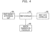
- FIG. 4 is a diagram illustrating an example of a hub according to the embodiment.
- FIG. 5 is a diagram illustrating an example of a superframe according to the embodiment.
- FIG. 6 is a diagram illustrating an example of a beacon frame according to the embodiment.
- FIG. 7 is a diagram illustrating an example of the beacon frame according to the embodiment.
- FIG. 8 is a diagram illustrating an example of a node according to the embodiment.
- FIG. 9 is a diagram illustrating an example of data that is transmitted from the node according to the embodiment.
- FIG. 10 is a diagram illustrating an example of the data that is transmitted from the node according to the embodiment.
- FIG. 11 is a diagram illustrating an example of setting of an urgent state
- FIG. 12 is a flowchart of an example of operations of the hub according to the embodiment.
- FIG. 13 is a diagram illustrating an example of the superframe according to the embodiment.
- FIG. 14 is a flowchart of an example of operations of the node according to the embodiment.
- FIG. 1 illustrates an example of a superframe for a non-beacon mode (hereinafter merely referred to as "non-beacon mode") with superframes.
- the abscissa indicates time.
- the non-beacon mode is a mode in which the schedule-based communication is executed.
- a superframe for the non-beacon mode includes a managed access phase (MAP).
- the MAP is a time period based on scheduled communication. In the MAP, the scheduled communication is executed using time division multiplexing.
- a node other than a node that executes scheduled communication may be in the sleep state, a hub may be in the sleep state for a time period in which the hub does not communicate with a node that has executed scheduling, and whereby power to be consumed may be reduced.
- the node in which the data is generated may not communicate with the hub and it is difficult to achieve immediate support.
- FIG. 2 illustrates a superframe for a beacon mode with beacon periods (superframes).
- the abscissa indicates time.
- the beacon mode is a mode in which both time period in which schedule-based communication is executed and time period in which the hub waits to receive unexpectedly generated urgent data from a node may be prepared.
- the superframe for the beacon mode includes an exclusive access phase (EAP), a random access phase (RAP), an MAP, and a contention access phase (CAP).
- EAP is a time period that may be used for urgent data and in which communication may be executed by carrier sense multiple access (CSMA).
- CSMA carrier sense multiple access
- the RAP and the CAP are time periods that may be used for data other than urgent data and in which communication may be executed by CSMA.
- a node other than a node that executes scheduled communication may be in the sleep state and the hub may be in the sleep state for a time period in which the hub does not communicate with a node that executes scheduling, and whereby power to be consumed may be reduced.
- the EAP and the RAP are supported for the case where data to be unexpectedly communicated is generated in a node.
- the hub waits for transmission of a beacon and access from a node in the EAP and the RAP during a normal operation, and it is difficult to reduce power to be consumed.
- the embodiment disclosed herein provides techniques for reducing power to be consumed and receiving unexpectedly generated data.
- FIG. 3 illustrates an example of a radio communication system according to the embodiment.
- the radio communication system includes a plurality of radio communication devices.
- Each of the radio communication devices includes a hub and a node.
- each of the hubs is set and thereby may communicate with one or more nodes.
- the hubs may be referred to as base units or coordinators.
- the nodes may be referred to as extensions.
- FIG. 3 mainly illustrates a hardware configuration of a hub 100 and a hardware configuration of a node 200.
- the embodiment of the radio communication system describes the case where radio communication is executed between the hub 100 and the node 200.
- the hub 100 and the node 200 transmit and receive a radio signal in accordance with IEEE802.15.6.
- the hub 100 and the node 200 may transmit and receive a radio signal in accordance with a communication method other than IEEE802.15.6.
- the hub 100 and the node 200 may transmit and receive a radio signal in accordance with IEEE802.15.4.
- the hub 100 includes a first antenna 102, a first transceiver 104, a first controller 106, and a mobile terminal 108.
- the first antenna 102, the first transceiver 104, and the first controller 106 may be achieved by a module.
- the first transceiver 104 transmits and receives a radio signal to and from the node 200.
- the first transceiver 104 may include a receiver for receiving a radio signal and a transmitter for transmitting a radio signal.
- the first controller 106 is connected to the first transceiver 104.
- the first controller 106 causes data to be input to the mobile terminal 108 from the first transceiver 104.
- the first controller 106 includes a first microcomputer 1062, a first storage device 1064, and a first interface (IF) 1066.
- the first microcomputer 1062 executes control in accordance with a program stored in the first storage device 1064.
- the first IF 1066 is an interface with the mobile terminal 108.
- the mobile terminal 108 transmits data received from the controller 106 to an external device (not illustrated).
- the external device includes a server.
- the mobile terminal 108 includes a CPU 1082, a second IF 1084, a display device 1086, a second storage device 1088, and a second transceiver 110.
- the CPU 1082 executes control in accordance with a program stored in the second storage device 1088. For example, the CPU 1082 controls transmission of data received from the first controller 106 from the second transceiver 110 to the external device. The CPU 1082 may control storage of the data received from the first controller 106 in the second storage device 1088. The CPU 1082 may control display of the data received from the first controller 106 on the display device 1086.
- the second IF 1084 is an interface with the first controller 106.
- the display device 1086 may display the data received from the first controller 106.
- the display device 1086 may display information indicating whether or not the data is urgent while displaying the data received from the first controller 106.
- the second storage device 1088 may store the data received from the first controller 106.
- the second transceiver 110 transmits and receives a radio signal to and from the external device.
- the second transceiver 110 may include a receiver for receiving a radio signal and a transmitter for transmitting a radio signal.
- the node 200 includes a third antenna 202, a third transceiver 204, a second controller 206, and a sensor 208.
- the third transceiver 204 transmits and receives a radio signal to and from the hub 100 through the third antenna 202.
- the third transceiver 204 may include a receiver for receiving a radio signal and a transmitter for transmitting a radio signal.
- the second controller 206 is connected to the third transceiver 204.
- the second controller 206 includes a second microcomputer 2062, a third storage device 2064, and a power supply 2066.
- the second microcomputer 2062 controls the node 200 in accordance with a program stored in the third storage device 2064.
- the power supply 2066 supplies power to the second microcomputer 2062, the third storage device 2064, and the like.
- the sensor 208 is connected to the second controller 206.
- the sensor 208 measures a target at which the node 100 is placed.
- the sensor 208 is placed on a human body.
- the sensor 208 includes an electrocardiograph, a pulse oximeter, a blood pressure monitor, a blood glucose meter, an electroencephalograph, or the like.
- the sensor 208 causes measured data to be input to the second controller 206.
- the measured data includes an electrocardiogram, a heart rate, a respiration rate, a pulse rate, a precutaneous arterial oxygen saturation (SpO2), blood pressure, a blood glucose value, an electroencephalogram, and the like.
- SpO2 precutaneous arterial oxygen saturation
- the measured data that is detected by the sensor 208 is periodically transmitted to the hub 100 from the node 200.
- the measured data that is detected by the sensor 208 may be randomly transmitted to the hub 100 from the node 200.
- the hub 100 transmits the measured data received from the node 200 to the external device.
- the external device may periodically acquire the measured data on the human body.
- the node 200 determines whether or not the measured data detected by the sensor 208 is normal. For example, the node 200 compares the measured data with a threshold and determines whether or not the measured data is normal. It is preferable that thresholds may be prepared for the measured data items. The thresholds may be prepared for time periods and different from each other. For example, the thresholds may be prepared for the morning, the daytime, and the night.
- FIG. 4 is a functional block diagram illustrating the hub 100.
- the first microcomputer 1062 functions as a first urgency determining unit 404, a first scheduler 402, a first state controller 406, and a beacon transmission controller 408.
- the first microcomputer 1062 functions in accordance with software stored in the first storage device 1064 and thereby functions as the first urgency determining unit 404, the first scheduler 402, the first state controller 406, and the beacon transmission controller 408.
- the first microcomputer 1062 may function in accordance with firmware and thereby function as the first urgency determining unit 404, the first scheduler 402, the first state controller 406, and the beacon transmission controller 408.
- the first scheduler 402 schedules communication with the node 200. For example, the first scheduler 402 schedules the communication in accordance with a superframe that includes a time period in which schedule-based communication is executed and a time period in which the hub 100 may wait to receive unexpectedly generated urgent data from the node 200.
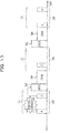
- FIG. 5 illustrates an example of the superframe according to the embodiment.
- the abscissa indicates time.
- the superframe illustrated in FIG. 5 includes time periods (hereinafter referred to as "beacon periods 502") in which a beacon is transmitted.
- the superframe includes a time period in which the hub 100 may communicate with a node that has accessed the hub 100 by a competitive access method and time periods (hereinafter referred to as "MAP periods 506") in which the hub 100 may communicate with a scheduled node.
- the competitive access method may be CSMA, ALOHA, slotted ALOHA, or the like.
- CSMA is described. The same applies to the cases where ALOHA, slotted ALOHA, and the like are used.
- CSMA periods 504 Time periods in which the hub 100 and a node that has accessed the hub 100 by CSMA may communicate with each other are referred to as "CSMA periods 504".
- the CSMA periods 504 are used for the case where the hub 100 receives urgent data from the node 200. Thus, a CSMA region is not normally set.
- a communication mode in which a CSMA period 504 is not used is referred to as a "communication mode A”
- a communication mode in which a CSMA period 504 is used is referred to as a "communication mode B”.
- the MAP period 506 (1) includes two time periods (indicated by "A” and “B") in which the hub 100 may communicate with a scheduled node.
- the MAP period 506 (2) includes one time period (indicated by "C") in which the hub 100 may communicate with a scheduled node.
- MAP period 506 (3) includes two time periods (indicated by "A” and "B") in which the hub 100 may communicate with a scheduled node.
- the hub 100 may communicate with a node A in the time periods indicated by "A”, communicate with a node B in the time periods indicated by “B”, and communicate with a node C in the time period indicted by "C".
- the hub 100 when receiving urgent data from the node 200, uses CSMA periods such as EAPs and RAPs.
- urgent data is generated in the node B within the MAP period 506 (1).
- the node B transmits the urgent data to the hub 100 within a time period allocated to the node B.
- the hub 100 enables the CSMA periods such as the EAPs and the RAPs to be used. Since the hub 100 enables the CSMA periods to be used, a node may communicate with the hub 100 in the CSMA periods.
- the nodes A, B, and C may communicate with the hub 100 in the CSMA periods after the MAP period 506 (1).
- the CSMA periods such as the EAPs and the RAPs are not used and communication is not executed until the hub 100 receives urgent data.
- the hub 100 may be in the sleep state for the CSMA periods 504 unless the hub 100 receives urgent data from the node 200.
- power to be consumed may be reduced. Since the CSMA periods such as the EAPs and RAPs may be used when a node detects urgent data, another node may transmit urgent data.
- the first urgency determining unit 404 is connected to the first scheduler 402.
- the first urgency determining unit 404 determines whether or not data received from the node 200 is urgent. For example, the first urgency determining unit 404 references a frame type included in the data received from the node 200 and determines whether or not the data is urgent. If the first urgency determining unit 404 determines that the data received from the node 200 is urgent, the first urgency determining unit 404 notifies the first scheduler 402 that the hub 100 has received the urgent data. For example, if the data received from the node 200 includes information that indicates that an urgency level is highest, the first urgency determining unit 404 may determine that the data is urgent. When the first scheduler 402 receives, from the first urgency determining unit 404, the notification indicating that the hub 100 has received the urgent data, the first scheduler 402 enables the CSMA periods 504 included in the superframe to be used.
- the first urgency determining unit 404 determines whether or not the data is semi-urgent. For example, if the data received from the node 200 includes information indicating an abnormal state, the first urgency determining unit 404 may determine that the data is semi-urgent. If the urgency determining unit 404 determines that the data received from the node 200 is semi-urgent, the first urgency determining unit 404 notifies the first scheduler 402 that the hub 100 has received the semi-urgent data.
- the first scheduler 402 If the first scheduler 402 receives, from the first urgency determining unit 404, the notification indicating that the hub 100 has received the semi-urgent data, the first scheduler 402 counts the number of times when the hub 100 receives semi-urgent data. If the first scheduler 402 confirms that the number of times when the hub 100 receives semi-urgent data is equal to or larger than a given threshold, the first scheduler 402 enables the CSMA periods 504 included in the superframe to be used. For example, if the first scheduler 402 confirms that the number of times when the hub 100 receives semi-urgent data within a given time period is equal to or larger than the given threshold, the first scheduler 402 may enable the CSMA periods 504 included in the superframe to be used. If the hub 100 does not receive semi-urgent data within a given time period after the hub 100 receives semi-urgent data, the first scheduler 402 may reset the number of times when the hub 100 receives semi-urgent data.
- the first urgency determining unit 404 determines that the data received from the node 200 is not urgent and semi-urgent, the first urgency determining unit 404 notifies the first scheduler 402 that the hub 100 has received the data. If the hub 100 receives data other than urgent data and semi-urgent data a given number of times after a change to the communication mode B, the first scheduler 402 changes the communication mode B to the communication mode A.
- the first scheduler 402 determines that the number of times when the hub 100 receives data other than urgent data and semi-urgent data within a given time period is equal to or larger than a given threshold. If the hub 100 does not receive data other than urgent data and semi-urgent data after a given time elapses after the hub 100 receives the data other than urgent data and semi-urgent data, the first scheduler 402 may reset the number of times when the hub 100 receives the data.
- the first scheduler 402 notifies the first state controller 406 whether the hub 100 executes communication in accordance with the communication mode A or B.
- the first state controller 406 controls the hub 100 so as to cause the hub 100 to be in the sleep state based on the communication mode notified by the first scheduler 402. For example, if the first scheduler 402 notifies the first state controller 406 of the communication mode A, the first state controller 406 controls the hub 100 so as to cause the hub 100 to be in the sleep state for time periods, each of which is included in any of the CSMA periods 504 and the MAP periods 506 and is not scheduled to be allocated to the node 200.
- the first state controller 406 controls the hub 100 so as to cause the hub 100 to be for the sleep state for time periods, each of which is included in any of the MAP periods 506 and is not scheduled to be allocated to the node 200.
- the beacon transmission controller 408 controls transmission of a beacon in accordance with scheduling by the first scheduler 402.
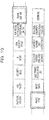
- FIG. 6 is a diagram illustrating an example of a beacon frame according to the embodiment.
- the beacon frame includes PLCP preamble, PLCP Header, MAC Header, MAC Frame Body, and FCS fields.
- FIG. 7 illustrates an example of the MAC Frame Body field included in the beacon frame according to the embodiment.
- the MAC Frame Body field includes Sender Address, Beacon Period Length, Allocation Slot Length, RAP1 End, RAP2 Start, RAP2 End, MAC Capability, PHY Capability, RAP1 Start, Beacon Shifting Sequence, Channel Hopping State, Next Channel Hop, and Inactive Duration fields.
- the beacon transmission controller 408 causes the beacon frame to include information specifying a CSMA period.
- the beacon transmission controller 408 specifies the CSMA period by inserting given information in the RAP1 Start, RAP1 End, RAP2 Start, and RAP2 End fields.
- the beacon transmission controller 408 may set a beacon period to be short.
- the beacon transmission controller 408 does not execute allocation in a time period scheduled for CSMA allocation. Since the beacon transmission controller 408 does not execute the allocation in the time period scheduled for CSMA allocation, the hub 100 may be in the sleep state for the time period in which the allocation is not executed, and whereby power to be consumed may be reduced.
- FIG. 8 is a functional block diagram illustrating the node 200.
- the second microcomputer 2062 functions as a second urgency determining unit 504, a second scheduler 502, a second state controller 506, and a carrier sense processor 508.
- the second microcomputer 2062 functions in accordance with software stored in the third storage device 2064 and thereby functions as the second urgency determining unit 504, the second scheduler 502, the second state controller 506, and the carrier sense processor 508.
- the second scheduler 502 controls transmission to the hub 100 in accordance with scheduling by the hub 100.
- the second scheduler 502 controls schedule-based communication and controls communication in CSMA periods.
- FIG. 9 illustrates an example of the format of a frame that is transmitted by the node 200.
- the frame includes PLCP Preamble, PLCP Header, MAC Header, MAC Frame Body, and FCS fields.
- the MAC header includes Frame Control, Recipient ID, Sender ID, and BAN ID fields.
- FIG. 10 illustrates an example of the format of the Frame Control field.
- the Frame Control field includes Protocol Version, Ack Policy, Security Level, TK Index, and BAN Security/Relay fields.
- the Frame Control field includes Ack Timing/EAP Indicator/First Frame On Time, Frame Subtype, Frame Type, and More Data fields.
- the Frame Control field includes Last Frame/Access Mode/B2, Sequence Number/Poll-Post Window, and Fragment Number/Next/Coexistence fields.
- the Frame Control field includes Non-final Fragment/Cancel/Scale/Inactive, and Reserved fields.
- FIG. 11 illustrates an example of values of the Frame Type and Frame Subtype fields.
- the second urgency determining unit 504 determines whether or not the measured data received from the sensor 208 is normal. For example, the second urgency determining unit 504 compares the measured data with a threshold and determines whether or not the measured data is normal. If the second urgency determining unit 504 determines that the measured data is abnormal, the second urgency determining unit 504 determines whether or not the measured data is urgent. For example, if a measurement item that is included in the measured data and related to human life is abnormal, the second urgency determining unit 504 may determine that the measured data is urgent. If the second urgency determining unit 504 determines that the measured data is urgent, the second urgency determining unit 504 causes the measured data including urgent information to be input to the second scheduler 502.
- the second scheduler 502 transmits, to the second state controller 506, a command to cause the node 200 to be restored from the sleep state.
- the second scheduler 502 transmits, to the carrier sense processor 508, a command to execute carrier sense.
- the carrier sense processor 508 executes the carrier sense in accordance with the command (received from the second scheduler 502) to execute the carrier sense. For example, the carrier sense processor 508 receives a beacon signal from the hub 100 and searches a CSMA period.
- the second scheduler 502 controls transmission of the measured data including the urgent information in the CSMA period searched by the carrier sense processor 508. In addition, the second scheduler 502 controls the transmission of the measured data including the urgent information at the time to transmit the measured data.
- FIG. 12 illustrates an example of operations of the radio communication system.
- FIG. 12 mainly illustrates an example of operations of the hub 100.
- step S1202 the hub 100 executes communication in the communication mode A.
- step S1204 the hub 100 receives data from the node 200.
- step S1206 the hub 100 determines whether or not the data received from the node 200 is urgent.
- the hub 100 determines that the data received from the node 200 is urgent, the hub 100 changes to the communication mode B in step S1208.
- step S1210 the hub 100 notifies the node 200 of a transition flag indicating the change to the communication mode B after the change to the communication mode B.
- the hub 100 transmits a beacon that includes information specifying a CSMA period.
- step S1206 the hub 100 determines whether or not the data is semi-urgent in step S1212. If the hub 100 determines that the data is not semi-urgent, a process illustrated in FIG. 12 returns to step S1202.
- the hub 100 determines that the data is semi-urgent in step S1212, the hub 100 increments a value of a semi-urgent data counter in step S1214.
- step S1216 the hub 100 determines whether or not the value of the semi-urgent data counter is equal to or larger than a first threshold. If the hub 100 determines that the value of the semi-urgent data counter is equal to or larger than the first threshold in step S1216, the process proceeds to step S1208. If the hub 100 determines that the value of the semi-urgent data counter is smaller than the first threshold in step S1216, the process returns to step S1202.
- the hub 100 may change to the communication mode A.
- the hub 100 and the node 200 communicate with each other in accordance with the beacon mode.
- the hub 100 allocates a CSMA period to the node 200.
- the hub 100 may be in the sleep state for the CSMA period until receiving the data including the urgent information from the node 200, and whereby power to be consumed may be reduced.
- the hub 100 may allocate the CSMA period to the node 200.
- the hub 100 may receive the urgent data.
- the hub 100 and the node 200 communicate with each other in accordance with the non-beacon mode.
- the mode is changed to the beacon mode.
- FIG. 13 illustrates an example of the superframe.
- the abscissa indicates time.
- the hub 100 and the node 200 communicate with each other in accordance with the non-beacon mode in the superframe illustrated in FIG. 13 .
- the superframe includes MAP periods.
- the MAP period 506 (1) includes two time periods (indicated by "A” and “B") in which the hub 100 may communicate with a scheduled node.
- the MAP period 506 (2) includes one time period (indicated by "C") in which the hub 100 may communicate with a scheduled node.
- the MAP period 506 (3) includes two time periods (indicated by "A” and "B") in which the hub 100 may communicate with a scheduled node.
- the hub 100 may communicate with the node A in the time periods indicated by "A”, communicate with the node B in the time periods indicated by "B", and communicate with the node C in the time period indicated by "C”.
- the hub 100 that receives urgent data within a MAP period changes from the non-beacon mode to the beacon mode.
- urgent data is generated in the node B within the MAP period 506 (1).
- the node B transmits the urgent data to the hub 100 within a time period allocated to the node B.
- the hub 100 changes to the beacon mode.
- the superframe after the hub 100 receives the urgent data includes beacon periods 502, CSMA periods 504, and the MAP periods 506.
- An example of the hub 100 is substantially the same as the hub 100 illustrated in FIG. 3 .
- a functional block diagram illustrating the example of the hub 100 is substantially the same as FIG. 4 .
- the first scheduler 402 schedules communication with the node 200. For example, the first scheduler 402 executes the scheduling in accordance with the non-communication mode and switches to the beacon mode when receiving urgent data from the node 200.
- the first urgency determining unit 404 is connected to the first scheduler 402.
- the first urgency determining unit 404 determines whether or not data received from the node 200 is urgent. For example, the first urgency determining unit 404 references a frame type included in the data received from the node 200 and determines whether or not the data is urgent. If the first urgency determining unit 404 determines that the data received from the node 200 is urgent, the first urgency determining unit 404 notifies the first scheduler 402 that the hub 100 has received the urgent data. For example, if the data received from the node 200 includes information indicating that an urgency level is highest, the first urgency determining unit 404 may determine that the data is urgent. When the first scheduler 402 receives, from the first urgency determining unit 404, the notification indicating that the hub 100 has received the urgent data, the first scheduler 402 switches from the non-beacon mode to the beacon mode.
- the first urgency determining unit 404 may determine whether or not the data received from the node 200 is semi-urgent. For example, the first urgency determining unit 404 references the frame type included in the data received from the node 200 and determines whether or not the data is semi-urgent. If the first urgency determining unit 404 determines that the data received from the node 200 is semi-urgent, the first urgency determining unit 404 notifies the first scheduler 402 that the hub 100 has received the semi-urgent data. When receiving the notification indicating that the hub 100 has received the semi-urgent data, the first scheduler 402 may switch from the non-beacon mode to the beacon mode.
- the first urgency determining unit 404 determines that the data received from the node 200 is not urgent, the first urgency determining unit 404 notifies the first scheduler 402 that the hub 100 has received the data.
- the hub 100 receives data other than urgent data and semi-urgent data a given number of times after a change to the communication mode B, the first urgency determining unit 404 may change the mode to the non-beacon mode.
- the first scheduler 402 may change the mode to the non-beacon mode. If the hub 100 does not receive the data other than urgent data and semi-urgent data after a given time elapses after reception of the data other than urgent data and semi-urgent data by the hub 100, the first scheduler 402 may reset the number of times when the hub 100 receives the data.
- the first scheduler 402 notifies the first state controller 406 whether the hub 100 executes communication in accordance with the non-beacon mode or the beacon mode.
- the first state controller 406 causes the hub 100 to be in the sleep state based on the communication mode notified by the first scheduler 402. For example, if the first state controller 406 receives the notification indicating the non-beacon mode from the first scheduler 402, the first state controller 406 causes the hub 100 to be in the sleep state for a time period that is not scheduled to be allocated to the node 200. If the first state controller 406 receives the notification indicating the beacon mode from the first scheduler 402, the first state controller 406 causes the hub 100 to be in the sleep state for a time period that is included in a MAP period 506 and is not scheduled to be allocated to the node 200.
- the beacon transmission controller 408 controls transmission of a beacon in accordance with scheduling by the first scheduler 402.
- An example of the node 200 is substantially the same as the node 200 illustrated in FIG. 3 .
- a functional block diagram of the example of the node 200 is substantially the same as FIG. 8 .
- the second scheduler 502 controls transmission to the hub 100 in accordance with scheduling by the hub 100.
- the second scheduler 502 controls communication of the beacon mode and communication of the non-beacon mode.
- the second urgency determining unit 504 determines whether or not the measured data received from the sensor 208 is normal. For example, the second urgency determining unit 504 compares the measured data with a threshold and determines whether or not the measured data is normal. If the second urgency determining unit 504 determines that the measured data is abnormal, the second urgency determining unit 504 determines whether or not the measured data is urgent. If the second urgency determining unit 504 determines that the measured data is urgent, the second urgency determining unit 504 notifies the second scheduler 502 of the measured data including urgent information. When receiving the measured data including the urgent information from the second urgency determining unit 504, the second scheduler 502 determines whether or not a time period from the current time to a time to transmit the measured data to the hub 100 is equal to or longer than a second threshold.
- the second scheduler 502 transmits, to the second state controller 506, the command to cause the node 200 to be restored from the sleep state.
- the second scheduler 502 transmits, to the carrier sense processor 508, the command to execute the carrier sense.
- the carrier sense processor 508 executes the carrier sense in accordance with the command (received from the second scheduler 502) to execute the carrier sense. For example, the carrier sense processor 508 receives a beacon signal from the hub 100 and searches a CSMA period.
- the second scheduler 502 controls transmission of the measured data including the urgent information at the time to transmit the measured data.
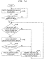
- FIG. 14 illustrates an example of operations of the radio communication system.
- FIG. 14 illustrates an example of operations of the node 200.
- step S1402 the node 200 executes communication in the non-beacon mode.
- step S1404 the node 200 determines whether or not urgent data is detected by the sensor 208.
- step S1404 If the node 200 determines that the urgent data is not detected by the sensor 208 in step S1404, a process illustrated in FIG. 14 returns to S1402.
- the node 200 determines whether or not a time period from the current time to a time to execute the next schedule is equal to or longer than the second threshold in step S1406.
- the node 200 determines that the time period to the time to execute the next schedule is equal to or longer than the second threshold in step S1406, the node 200 searches a CSMA period in step S1408. For example, the node 200 receives a beacon, acquires CSMA period information from the beacon, and searches the CSMA period.
- step S1410 the node 200 determines whether or not the CSMA period exists.
- step S1410 If the node 200 determines that the CSMA period exists in step S1410, the node 200 executes communication in the beacon mode in step S1412.
- the node 200 determines that the time period to the time to execute the next schedule is shorter than the second threshold in step S1406 or the node 200 determines that the CSMA does not exist in step S1410, the node 200 transmits data including a flag indicating urgency at the time to execute the next schedule in step S1414.
- the node 200 when the node 200 receives urgent data in the beacon mode, an EAP and a RAP that are included in a superframe are used. When the node 200 does not receive urgent data, the node 200 may be in the sleep state for the EAP and the RAP. Thus, while power to be consumed may be reduced, unexpectedly generated communication data may be received.
Landscapes
- Engineering & Computer Science (AREA)
- Signal Processing (AREA)
- Computer Networks & Wireless Communication (AREA)
- Mobile Radio Communication Systems (AREA)
- Time-Division Multiplex Systems (AREA)
Abstract
Description
- The embodiment discussed herein is related to a radio communication device, method for controlling radio communication, and a radio communication system.
- Body area networks (BANs) are known (refer to, for example, IEEE802.15.6). The BANs are very short distance radio communication networks for medical care and health care.
- For a BAN, a sensor (hereinafter referred to as "node") is downsized. In addition, for the BAN, a gateway device (hereinafter referred to as "hub") is downsized and a battery is used for driving. It is, therefore, preferable to save power for the overall network. If data that is detected by the node indicates urgency, the data is reliably transmitted with a short delay time.
- A technique for allocating a slot for urgent data to a superframe and providing slot allocation information for the urgent data to a node is known (refer to, for example, Japanese Laid-open Patent Publication No.
2011-87295 - Accordingly, it is an object in one aspect of the embodiment to reduce consumption power and receive unexpectedly generated data.
- According to an aspect of the invention, a radio communication device includes: a receiver configured to receive a radio signal; and a controller configured to switch between a first communication mode and a second communication mode in accordance with scheduling of allocation of a time slot to another radio communication device based on the radio signal, communication between the radio communication device and the another radio communication device being executed using time division multiplexing in the first communication mode, and communication between the radio communication device and the another radio communication device being executed using a competitive access method in the second communication mode.
-
FIG. 1 is a diagram illustrating an example of a superframe for a non-beacon mode with superframes; -
FIG. 2 is a diagram illustrating an example of a superframe for a beacon mode; -
FIG. 3 is a diagram illustrating an example of a radio communication system according to the embodiment; -
FIG. 4 is a diagram illustrating an example of a hub according to the embodiment; -
FIG. 5 is a diagram illustrating an example of a superframe according to the embodiment; -
FIG. 6 is a diagram illustrating an example of a beacon frame according to the embodiment; -
FIG. 7 is a diagram illustrating an example of the beacon frame according to the embodiment; -
FIG. 8 is a diagram illustrating an example of a node according to the embodiment; -
FIG. 9 is a diagram illustrating an example of data that is transmitted from the node according to the embodiment; -
FIG. 10 is a diagram illustrating an example of the data that is transmitted from the node according to the embodiment; -
FIG. 11 is a diagram illustrating an example of setting of an urgent state; -
FIG. 12 is a flowchart of an example of operations of the hub according to the embodiment; -
FIG. 13 is a diagram illustrating an example of the superframe according to the embodiment; and -
FIG. 14 is a flowchart of an example of operations of the node according to the embodiment. - Hereinafter, the embodiment is described with reference to the accompanying drawings.
- In all the drawings describing the embodiment, parts that have the same functions are indicated by the same reference numerals, and repetitive descriptions are omitted.
- While inventing the present embodiments, observations were made regarding a related art. Such observations include the following, for example.
- In the radio communication networks of the related art, in order to save energy for an overall network, it is effective to execute schedule-based communication and change the states of a hub and node to sleep states.
-
FIG. 1 illustrates an example of a superframe for a non-beacon mode (hereinafter merely referred to as "non-beacon mode") with superframes. InFIG. 1 , the abscissa indicates time. The non-beacon mode is a mode in which the schedule-based communication is executed. A superframe for the non-beacon mode includes a managed access phase (MAP). The MAP is a time period based on scheduled communication. In the MAP, the scheduled communication is executed using time division multiplexing. In the non-beacon mode, a node other than a node that executes scheduled communication may be in the sleep state, a hub may be in the sleep state for a time period in which the hub does not communicate with a node that has executed scheduling, and whereby power to be consumed may be reduced. When data is unexpectedly generated in a node other than scheduled nodes, the node in which the data is generated may not communicate with the hub and it is difficult to achieve immediate support. - In order to achieve immediate support upon urgency, it is effective to enable the hub to frequently receive data and wait to receive urgent data from a node on a priority basis.
-
FIG. 2 illustrates a superframe for a beacon mode with beacon periods (superframes). InFIG. 2 , the abscissa indicates time. The beacon mode is a mode in which both time period in which schedule-based communication is executed and time period in which the hub waits to receive unexpectedly generated urgent data from a node may be prepared. The superframe for the beacon mode includes an exclusive access phase (EAP), a random access phase (RAP), an MAP, and a contention access phase (CAP). The EAP is a time period that may be used for urgent data and in which communication may be executed by carrier sense multiple access (CSMA). The RAP and the CAP are time periods that may be used for data other than urgent data and in which communication may be executed by CSMA. In the MAP, a node other than a node that executes scheduled communication may be in the sleep state and the hub may be in the sleep state for a time period in which the hub does not communicate with a node that executes scheduling, and whereby power to be consumed may be reduced. The EAP and the RAP are supported for the case where data to be unexpectedly communicated is generated in a node. In the beacon mode, however, the hub waits for transmission of a beacon and access from a node in the EAP and the RAP during a normal operation, and it is difficult to reduce power to be consumed. - Therefore, the embodiment disclosed herein, for example, provides techniques for reducing power to be consumed and receiving unexpectedly generated data.
- (Radio communication system)
-
FIG. 3 illustrates an example of a radio communication system according to the embodiment. - The radio communication system includes a plurality of radio communication devices. Each of the radio communication devices includes a hub and a node. In this case, each of the hubs is set and thereby may communicate with one or more nodes. The hubs may be referred to as base units or coordinators. The nodes may be referred to as extensions.
FIG. 3 mainly illustrates a hardware configuration of ahub 100 and a hardware configuration of anode 200. - The embodiment of the radio communication system describes the case where radio communication is executed between the
hub 100 and thenode 200. In the embodiment of the radio communication system, thehub 100 and thenode 200 transmit and receive a radio signal in accordance with IEEE802.15.6. Thehub 100 and thenode 200 may transmit and receive a radio signal in accordance with a communication method other than IEEE802.15.6. For example, thehub 100 and thenode 200 may transmit and receive a radio signal in accordance with IEEE802.15.4. - (Hub 100)
- The
hub 100 includes afirst antenna 102, afirst transceiver 104, afirst controller 106, and amobile terminal 108. Thefirst antenna 102, thefirst transceiver 104, and thefirst controller 106 may be achieved by a module. - The
first transceiver 104 transmits and receives a radio signal to and from thenode 200. Thefirst transceiver 104 may include a receiver for receiving a radio signal and a transmitter for transmitting a radio signal. - The
first controller 106 is connected to thefirst transceiver 104. Thefirst controller 106 causes data to be input to the mobile terminal 108 from thefirst transceiver 104. Thefirst controller 106 includes afirst microcomputer 1062, afirst storage device 1064, and a first interface (IF) 1066. - The
first microcomputer 1062 executes control in accordance with a program stored in thefirst storage device 1064. - The first IF 1066 is an interface with the
mobile terminal 108. - The
mobile terminal 108 transmits data received from thecontroller 106 to an external device (not illustrated). The external device includes a server. Themobile terminal 108 includes aCPU 1082, a second IF 1084, adisplay device 1086, asecond storage device 1088, and asecond transceiver 110. - The
CPU 1082 executes control in accordance with a program stored in thesecond storage device 1088. For example, theCPU 1082 controls transmission of data received from thefirst controller 106 from thesecond transceiver 110 to the external device. TheCPU 1082 may control storage of the data received from thefirst controller 106 in thesecond storage device 1088. TheCPU 1082 may control display of the data received from thefirst controller 106 on thedisplay device 1086. - The second IF 1084 is an interface with the
first controller 106. - The
display device 1086 may display the data received from thefirst controller 106. Thedisplay device 1086 may display information indicating whether or not the data is urgent while displaying the data received from thefirst controller 106. - The
second storage device 1088 may store the data received from thefirst controller 106. - The
second transceiver 110 transmits and receives a radio signal to and from the external device. Thesecond transceiver 110 may include a receiver for receiving a radio signal and a transmitter for transmitting a radio signal. - (Node 200)
- The
node 200 includes athird antenna 202, athird transceiver 204, asecond controller 206, and asensor 208. - The
third transceiver 204 transmits and receives a radio signal to and from thehub 100 through thethird antenna 202. Thethird transceiver 204 may include a receiver for receiving a radio signal and a transmitter for transmitting a radio signal. - The
second controller 206 is connected to thethird transceiver 204. Thesecond controller 206 includes asecond microcomputer 2062, athird storage device 2064, and apower supply 2066. - The
second microcomputer 2062 controls thenode 200 in accordance with a program stored in thethird storage device 2064. - The
power supply 2066 supplies power to thesecond microcomputer 2062, thethird storage device 2064, and the like. - The
sensor 208 is connected to thesecond controller 206. Thesensor 208 measures a target at which thenode 100 is placed. In the example, thesensor 208 is placed on a human body. Thesensor 208 includes an electrocardiograph, a pulse oximeter, a blood pressure monitor, a blood glucose meter, an electroencephalograph, or the like. Thesensor 208 causes measured data to be input to thesecond controller 206. The measured data includes an electrocardiogram, a heart rate, a respiration rate, a pulse rate, a precutaneous arterial oxygen saturation (SpO2), blood pressure, a blood glucose value, an electroencephalogram, and the like. - In the embodiment of the radio communication system, the measured data that is detected by the
sensor 208 is periodically transmitted to thehub 100 from thenode 200. The measured data that is detected by thesensor 208 may be randomly transmitted to thehub 100 from thenode 200. Thehub 100 transmits the measured data received from thenode 200 to the external device. Thus, the external device may periodically acquire the measured data on the human body. - The
node 200 determines whether or not the measured data detected by thesensor 208 is normal. For example, thenode 200 compares the measured data with a threshold and determines whether or not the measured data is normal. It is preferable that thresholds may be prepared for the measured data items. The thresholds may be prepared for time periods and different from each other. For example, the thresholds may be prepared for the morning, the daytime, and the night. - (Functions of Hub 100)
-
FIG. 4 is a functional block diagram illustrating thehub 100. - The
first microcomputer 1062 functions as a firsturgency determining unit 404, afirst scheduler 402, afirst state controller 406, and abeacon transmission controller 408. For example, thefirst microcomputer 1062 functions in accordance with software stored in thefirst storage device 1064 and thereby functions as the firsturgency determining unit 404, thefirst scheduler 402, thefirst state controller 406, and thebeacon transmission controller 408. For example, thefirst microcomputer 1062 may function in accordance with firmware and thereby function as the firsturgency determining unit 404, thefirst scheduler 402, thefirst state controller 406, and thebeacon transmission controller 408. - The
first scheduler 402 schedules communication with thenode 200. For example, thefirst scheduler 402 schedules the communication in accordance with a superframe that includes a time period in which schedule-based communication is executed and a time period in which thehub 100 may wait to receive unexpectedly generated urgent data from thenode 200. -
FIG. 5 illustrates an example of the superframe according to the embodiment. InFIG. 5 , the abscissa indicates time. - The superframe illustrated in
FIG. 5 includes time periods (hereinafter referred to as "beacon periods 502") in which a beacon is transmitted. In addition, the superframe includes a time period in which thehub 100 may communicate with a node that has accessed thehub 100 by a competitive access method and time periods (hereinafter referred to as "MAP periods 506") in which thehub 100 may communicate with a scheduled node. The competitive access method may be CSMA, ALOHA, slotted ALOHA, or the like. In the example of the superframe, CSMA is described. The same applies to the cases where ALOHA, slotted ALOHA, and the like are used. Time periods in which thehub 100 and a node that has accessed thehub 100 by CSMA may communicate with each other are referred to as "CSMA periods 504". TheCSMA periods 504 are used for the case where thehub 100 receives urgent data from thenode 200. Thus, a CSMA region is not normally set. Hereinafter, a communication mode in which aCSMA period 504 is not used is referred to as a "communication mode A", and a communication mode in which aCSMA period 504 is used is referred to as a "communication mode B". - In the example illustrated in
FIG. 5 , three MAP periods 506 (1) to (3) are illustrated. The MAP period 506 (1) includes two time periods (indicated by "A" and "B") in which thehub 100 may communicate with a scheduled node. The MAP period 506 (2) includes one time period (indicated by "C") in which thehub 100 may communicate with a scheduled node. MAP period 506 (3) includes two time periods (indicated by "A" and "B") in which thehub 100 may communicate with a scheduled node. - For example, it is assumed that the
hub 100 may communicate with a node A in the time periods indicated by "A", communicate with a node B in the time periods indicated by "B", and communicate with a node C in the time period indicted by "C". - In the example of the superframe, in the beacon mode, when receiving urgent data from the
node 200, thehub 100 uses CSMA periods such as EAPs and RAPs. In the example illustrated inFIG. 5 , urgent data is generated in the node B within the MAP period 506 (1). The node B transmits the urgent data to thehub 100 within a time period allocated to the node B. When receiving the urgent data, thehub 100 enables the CSMA periods such as the EAPs and the RAPs to be used. Since thehub 100 enables the CSMA periods to be used, a node may communicate with thehub 100 in the CSMA periods. In the example illustrated inFIG. 5 , the nodes A, B, and C may communicate with thehub 100 in the CSMA periods after the MAP period 506 (1). - The CSMA periods such as the EAPs and the RAPs are not used and communication is not executed until the
hub 100 receives urgent data. Thus, thehub 100 may be in the sleep state for theCSMA periods 504 unless thehub 100 receives urgent data from thenode 200. Thus, power to be consumed may be reduced. Since the CSMA periods such as the EAPs and RAPs may be used when a node detects urgent data, another node may transmit urgent data. - The first
urgency determining unit 404 is connected to thefirst scheduler 402. The firsturgency determining unit 404 determines whether or not data received from thenode 200 is urgent. For example, the firsturgency determining unit 404 references a frame type included in the data received from thenode 200 and determines whether or not the data is urgent. If the firsturgency determining unit 404 determines that the data received from thenode 200 is urgent, the firsturgency determining unit 404 notifies thefirst scheduler 402 that thehub 100 has received the urgent data. For example, if the data received from thenode 200 includes information that indicates that an urgency level is highest, the firsturgency determining unit 404 may determine that the data is urgent. When thefirst scheduler 402 receives, from the firsturgency determining unit 404, the notification indicating that thehub 100 has received the urgent data, thefirst scheduler 402 enables theCSMA periods 504 included in the superframe to be used. - If the first
urgency determining unit 404 determines that the data received from thenode 200 is not urgent, the firsturgency determining unit 404 determines whether or not the data is semi-urgent. For example, if the data received from thenode 200 includes information indicating an abnormal state, the firsturgency determining unit 404 may determine that the data is semi-urgent. If theurgency determining unit 404 determines that the data received from thenode 200 is semi-urgent, the firsturgency determining unit 404 notifies thefirst scheduler 402 that thehub 100 has received the semi-urgent data. If thefirst scheduler 402 receives, from the firsturgency determining unit 404, the notification indicating that thehub 100 has received the semi-urgent data, thefirst scheduler 402 counts the number of times when thehub 100 receives semi-urgent data. If thefirst scheduler 402 confirms that the number of times when thehub 100 receives semi-urgent data is equal to or larger than a given threshold, thefirst scheduler 402 enables theCSMA periods 504 included in the superframe to be used. For example, if thefirst scheduler 402 confirms that the number of times when thehub 100 receives semi-urgent data within a given time period is equal to or larger than the given threshold, thefirst scheduler 402 may enable theCSMA periods 504 included in the superframe to be used. If thehub 100 does not receive semi-urgent data within a given time period after thehub 100 receives semi-urgent data, thefirst scheduler 402 may reset the number of times when thehub 100 receives semi-urgent data. - If the first
urgency determining unit 404 determines that the data received from thenode 200 is not urgent and semi-urgent, the firsturgency determining unit 404 notifies thefirst scheduler 402 that thehub 100 has received the data. If thehub 100 receives data other than urgent data and semi-urgent data a given number of times after a change to the communication mode B, thefirst scheduler 402 changes the communication mode B to the communication mode A. - For example, if the
first scheduler 402 confirms that the number of times when thehub 100 receives data other than urgent data and semi-urgent data within a given time period is equal to or larger than a given threshold, thefirst scheduler 402 changes the communication mode B to the communication mode A. If thehub 100 does not receive data other than urgent data and semi-urgent data after a given time elapses after thehub 100 receives the data other than urgent data and semi-urgent data, thefirst scheduler 402 may reset the number of times when thehub 100 receives the data. - The
first scheduler 402 notifies thefirst state controller 406 whether thehub 100 executes communication in accordance with the communication mode A or B. - The
first state controller 406 controls thehub 100 so as to cause thehub 100 to be in the sleep state based on the communication mode notified by thefirst scheduler 402. For example, if thefirst scheduler 402 notifies thefirst state controller 406 of the communication mode A, thefirst state controller 406 controls thehub 100 so as to cause thehub 100 to be in the sleep state for time periods, each of which is included in any of theCSMA periods 504 and theMAP periods 506 and is not scheduled to be allocated to thenode 200. For example, if thefirst scheduler 402 notifies thefirst state controller 406 of the communication mode B, thefirst state controller 406 controls thehub 100 so as to cause thehub 100 to be for the sleep state for time periods, each of which is included in any of theMAP periods 506 and is not scheduled to be allocated to thenode 200. - The
beacon transmission controller 408 controls transmission of a beacon in accordance with scheduling by thefirst scheduler 402. -
FIG. 6 is a diagram illustrating an example of a beacon frame according to the embodiment. - The beacon frame includes PLCP preamble, PLCP Header, MAC Header, MAC Frame Body, and FCS fields.
-
FIG. 7 illustrates an example of the MAC Frame Body field included in the beacon frame according to the embodiment. - The MAC Frame Body field includes Sender Address, Beacon Period Length, Allocation Slot Length, RAP1 End, RAP2 Start, RAP2 End, MAC Capability, PHY Capability, RAP1 Start, Beacon Shifting Sequence, Channel Hopping State, Next Channel Hop, and Inactive Duration fields.
- When the
hub 100 executes communication in the communication mode B in accordance with scheduling by thefirst scheduler 402, thebeacon transmission controller 408 causes the beacon frame to include information specifying a CSMA period. For example, thebeacon transmission controller 408 specifies the CSMA period by inserting given information in the RAP1 Start, RAP1 End, RAP2 Start, and RAP2 End fields. - When the
hub 100 executes communication in the communication mode A, thebeacon transmission controller 408 may set a beacon period to be short. When thehub 100 executes communication in the communication mode B, thebeacon transmission controller 408 does not execute allocation in a time period scheduled for CSMA allocation. Since thebeacon transmission controller 408 does not execute the allocation in the time period scheduled for CSMA allocation, thehub 100 may be in the sleep state for the time period in which the allocation is not executed, and whereby power to be consumed may be reduced. - (Functions of Node 200)
-
FIG. 8 is a functional block diagram illustrating thenode 200. - The
second microcomputer 2062 functions as a secondurgency determining unit 504, asecond scheduler 502, asecond state controller 506, and acarrier sense processor 508. For example, thesecond microcomputer 2062 functions in accordance with software stored in thethird storage device 2064 and thereby functions as the secondurgency determining unit 504, thesecond scheduler 502, thesecond state controller 506, and thecarrier sense processor 508. - The
second scheduler 502 controls transmission to thehub 100 in accordance with scheduling by thehub 100. For example, thesecond scheduler 502 controls schedule-based communication and controls communication in CSMA periods. -
FIG. 9 illustrates an example of the format of a frame that is transmitted by thenode 200. - The frame includes PLCP Preamble, PLCP Header, MAC Header, MAC Frame Body, and FCS fields.
- The MAC header includes Frame Control, Recipient ID, Sender ID, and BAN ID fields.
-
FIG. 10 illustrates an example of the format of the Frame Control field. The Frame Control field includes Protocol Version, Ack Policy, Security Level, TK Index, and BAN Security/Relay fields. In addition, the Frame Control field includes Ack Timing/EAP Indicator/First Frame On Time, Frame Subtype, Frame Type, and More Data fields. In addition, the Frame Control field includes Last Frame/Access Mode/B2, Sequence Number/Poll-Post Window, and Fragment Number/Next/Coexistence fields. Furthermore, the Frame Control field includes Non-final Fragment/Cancel/Scale/Inactive, and Reserved fields. -
FIG. 11 illustrates an example of values of the Frame Type and Frame Subtype fields. - Referring to
FIG. 11 , "10 " is stored in a Frame Type value b5b4 field, and "0111" is stored in a Frame Subtype value b3b2b1b0 field, and whereby the Frame Control field may specify data that is urgent. - The second
urgency determining unit 504 determines whether or not the measured data received from thesensor 208 is normal. For example, the secondurgency determining unit 504 compares the measured data with a threshold and determines whether or not the measured data is normal. If the secondurgency determining unit 504 determines that the measured data is abnormal, the secondurgency determining unit 504 determines whether or not the measured data is urgent. For example, if a measurement item that is included in the measured data and related to human life is abnormal, the secondurgency determining unit 504 may determine that the measured data is urgent. If the secondurgency determining unit 504 determines that the measured data is urgent, the secondurgency determining unit 504 causes the measured data including urgent information to be input to thesecond scheduler 502. If the measured data including the urgent information is input to thesecond scheduler 502 from the secondurgency determining unit 504, thesecond scheduler 502 transmits, to thesecond state controller 506, a command to cause thenode 200 to be restored from the sleep state. In addition, thesecond scheduler 502 transmits, to thecarrier sense processor 508, a command to execute carrier sense. - The
carrier sense processor 508 executes the carrier sense in accordance with the command (received from the second scheduler 502) to execute the carrier sense. For example, thecarrier sense processor 508 receives a beacon signal from thehub 100 and searches a CSMA period. - The
second scheduler 502 controls transmission of the measured data including the urgent information in the CSMA period searched by thecarrier sense processor 508. In addition, thesecond scheduler 502 controls the transmission of the measured data including the urgent information at the time to transmit the measured data. - (Operations of Radio Communication System)
-
FIG. 12 illustrates an example of operations of the radio communication system.FIG. 12 mainly illustrates an example of operations of thehub 100. - In step S1202, the
hub 100 executes communication in the communication mode A. - In step S1204, the
hub 100 receives data from thenode 200. - In step S1206, the
hub 100 determines whether or not the data received from thenode 200 is urgent. - If the
hub 100 determines that the data received from thenode 200 is urgent, thehub 100 changes to the communication mode B in step S1208. - In step S1210, the
hub 100 notifies thenode 200 of a transition flag indicating the change to the communication mode B after the change to the communication mode B. For example, thehub 100 transmits a beacon that includes information specifying a CSMA period. - If the
hub 100 determines that the data received from thenode 200 is not urgent in step S1206, thehub 100 determines whether or not the data is semi-urgent in step S1212. If thehub 100 determines that the data is not semi-urgent, a process illustrated inFIG. 12 returns to step S1202. - If the
hub 100 determines that the data is semi-urgent in step S1212, thehub 100 increments a value of a semi-urgent data counter in step S1214. - In step S1216, the
hub 100 determines whether or not the value of the semi-urgent data counter is equal to or larger than a first threshold. If thehub 100 determines that the value of the semi-urgent data counter is equal to or larger than the first threshold in step S1216, the process proceeds to step S1208. If thehub 100 determines that the value of the semi-urgent data counter is smaller than the first threshold in step S1216, the process returns to step S1202. - When the
hub 100 receives data other than urgent data and semi-urgent data from the node 200 a given number of times after changing to the communication mode B, thehub 100 may change to the communication mode A. - In the embodiment of the radio communication system, the
hub 100 and thenode 200 communicate with each other in accordance with the beacon mode. When receiving data including urgent information from thenode 200, thehub 100 allocates a CSMA period to thenode 200. Thus, thehub 100 may be in the sleep state for the CSMA period until receiving the data including the urgent information from thenode 200, and whereby power to be consumed may be reduced. When receiving the data including the urgent information from thenode 200, thehub 100 may allocate the CSMA period to thenode 200. Thus, when urgent data is generated in thenode 200, thehub 100 may receive the urgent data. - (Modified Example)
- In a modified example of the radio communication system, the
hub 100 and thenode 200 communicate with each other in accordance with the non-beacon mode. When urgent data is generated in thenode 200 and received by thehub 100, the mode is changed to the beacon mode. -
FIG. 13 illustrates an example of the superframe. InFIG. 13 , the abscissa indicates time. - Before urgent data is generated in the
node 200 and received by thehub 100, thehub 100 and thenode 200 communicate with each other in accordance with the non-beacon mode in the superframe illustrated inFIG. 13 . Thus, the superframe includes MAP periods. - In the example illustrated in
FIG. 13 , three MAP periods 506 (1) to (3) are illustrated. The MAP period 506 (1) includes two time periods (indicated by "A" and "B") in which thehub 100 may communicate with a scheduled node. The MAP period 506 (2) includes one time period (indicated by "C") in which thehub 100 may communicate with a scheduled node. The MAP period 506 (3) includes two time periods (indicated by "A" and "B") in which thehub 100 may communicate with a scheduled node. - For example, it is assumed that the
hub 100 may communicate with the node A in the time periods indicated by "A", communicate with the node B in the time periods indicated by "B", and communicate with the node C in the time period indicated by "C". - The
hub 100 that receives urgent data within a MAP period changes from the non-beacon mode to the beacon mode. In the example illustrated inFIG. 13 , urgent data is generated in the node B within the MAP period 506 (1). The node B transmits the urgent data to thehub 100 within a time period allocated to the node B. When receiving the urgent data, thehub 100 changes to the beacon mode. Thus, the superframe after thehub 100 receives the urgent data includesbeacon periods 502,CSMA periods 504, and theMAP periods 506. - (Hub 100)
- An example of the
hub 100 is substantially the same as thehub 100 illustrated inFIG. 3 . - A functional block diagram illustrating the example of the
hub 100 is substantially the same asFIG. 4 . - The
first scheduler 402 schedules communication with thenode 200. For example, thefirst scheduler 402 executes the scheduling in accordance with the non-communication mode and switches to the beacon mode when receiving urgent data from thenode 200. - The first
urgency determining unit 404 is connected to thefirst scheduler 402. The firsturgency determining unit 404 determines whether or not data received from thenode 200 is urgent. For example, the firsturgency determining unit 404 references a frame type included in the data received from thenode 200 and determines whether or not the data is urgent. If the firsturgency determining unit 404 determines that the data received from thenode 200 is urgent, the firsturgency determining unit 404 notifies thefirst scheduler 402 that thehub 100 has received the urgent data. For example, if the data received from thenode 200 includes information indicating that an urgency level is highest, the firsturgency determining unit 404 may determine that the data is urgent. When thefirst scheduler 402 receives, from the firsturgency determining unit 404, the notification indicating that thehub 100 has received the urgent data, thefirst scheduler 402 switches from the non-beacon mode to the beacon mode. - The first
urgency determining unit 404 may determine whether or not the data received from thenode 200 is semi-urgent. For example, the firsturgency determining unit 404 references the frame type included in the data received from thenode 200 and determines whether or not the data is semi-urgent. If the firsturgency determining unit 404 determines that the data received from thenode 200 is semi-urgent, the firsturgency determining unit 404 notifies thefirst scheduler 402 that thehub 100 has received the semi-urgent data. When receiving the notification indicating that thehub 100 has received the semi-urgent data, thefirst scheduler 402 may switch from the non-beacon mode to the beacon mode. - If the first
urgency determining unit 404 determines that the data received from thenode 200 is not urgent, the firsturgency determining unit 404 notifies thefirst scheduler 402 that thehub 100 has received the data. When thehub 100 receives data other than urgent data and semi-urgent data a given number of times after a change to the communication mode B, the firsturgency determining unit 404 may change the mode to the non-beacon mode. - For example, when the
first scheduler 402 confirms that the number of times when thehub 100 receives data other than urgent data and semi-urgent data within a given time period is equal to or larger than a given threshold, thefirst scheduler 402 may change the mode to the non-beacon mode. If thehub 100 does not receive the data other than urgent data and semi-urgent data after a given time elapses after reception of the data other than urgent data and semi-urgent data by thehub 100, thefirst scheduler 402 may reset the number of times when thehub 100 receives the data. - The
first scheduler 402 notifies thefirst state controller 406 whether thehub 100 executes communication in accordance with the non-beacon mode or the beacon mode. - The
first state controller 406 causes thehub 100 to be in the sleep state based on the communication mode notified by thefirst scheduler 402. For example, if thefirst state controller 406 receives the notification indicating the non-beacon mode from thefirst scheduler 402, thefirst state controller 406 causes thehub 100 to be in the sleep state for a time period that is not scheduled to be allocated to thenode 200. If thefirst state controller 406 receives the notification indicating the beacon mode from thefirst scheduler 402, thefirst state controller 406 causes thehub 100 to be in the sleep state for a time period that is included in aMAP period 506 and is not scheduled to be allocated to thenode 200. - The
beacon transmission controller 408 controls transmission of a beacon in accordance with scheduling by thefirst scheduler 402. - (Node 200)
- An example of the
node 200 is substantially the same as thenode 200 illustrated inFIG. 3 . - A functional block diagram of the example of the
node 200 is substantially the same asFIG. 8 . - The
second scheduler 502 controls transmission to thehub 100 in accordance with scheduling by thehub 100. For example, thesecond scheduler 502 controls communication of the beacon mode and communication of the non-beacon mode. - The second
urgency determining unit 504 determines whether or not the measured data received from thesensor 208 is normal. For example, the secondurgency determining unit 504 compares the measured data with a threshold and determines whether or not the measured data is normal. If the secondurgency determining unit 504 determines that the measured data is abnormal, the secondurgency determining unit 504 determines whether or not the measured data is urgent. If the secondurgency determining unit 504 determines that the measured data is urgent, the secondurgency determining unit 504 notifies thesecond scheduler 502 of the measured data including urgent information. When receiving the measured data including the urgent information from the secondurgency determining unit 504, thesecond scheduler 502 determines whether or not a time period from the current time to a time to transmit the measured data to thehub 100 is equal to or longer than a second threshold. - If the time period to the time to transmit the measured data to the
hub 100 is equal to or longer than the second threshold, thesecond scheduler 502 transmits, to thesecond state controller 506, the command to cause thenode 200 to be restored from the sleep state. In addition, thesecond scheduler 502 transmits, to thecarrier sense processor 508, the command to execute the carrier sense. - The
carrier sense processor 508 executes the carrier sense in accordance with the command (received from the second scheduler 502) to execute the carrier sense. For example, thecarrier sense processor 508 receives a beacon signal from thehub 100 and searches a CSMA period. - If the time period to the time to transmit the measured data to the
hub 100 is shorter than the second threshold, thesecond scheduler 502 controls transmission of the measured data including the urgent information at the time to transmit the measured data. -
FIG. 14 illustrates an example of operations of the radio communication system.FIG. 14 illustrates an example of operations of thenode 200. - In step S1402, the
node 200 executes communication in the non-beacon mode. - In step S1404, the
node 200 determines whether or not urgent data is detected by thesensor 208. - If the
node 200 determines that the urgent data is not detected by thesensor 208 in step S1404, a process illustrated inFIG. 14 returns to S1402. - If the
node 200 determines that the urgent data is detected by thesensor 208 in step S1404, thenode 200 determines whether or not a time period from the current time to a time to execute the next schedule is equal to or longer than the second threshold in step S1406. - If the
node 200 determines that the time period to the time to execute the next schedule is equal to or longer than the second threshold in step S1406, thenode 200 searches a CSMA period in step S1408. For example, thenode 200 receives a beacon, acquires CSMA period information from the beacon, and searches the CSMA period. - In step S1410, the
node 200 determines whether or not the CSMA period exists. - If the
node 200 determines that the CSMA period exists in step S1410, thenode 200 executes communication in the beacon mode in step S1412. - If the
node 200 determines that the time period to the time to execute the next schedule is shorter than the second threshold in step S1406 or thenode 200 determines that the CSMA does not exist in step S1410, thenode 200 transmits data including a flag indicating urgency at the time to execute the next schedule in step S1414. - According to the embodiment of the radio communication system, when the
node 200 receives urgent data in the beacon mode, an EAP and a RAP that are included in a superframe are used. When thenode 200 does not receive urgent data, thenode 200 may be in the sleep state for the EAP and the RAP. Thus, while power to be consumed may be reduced, unexpectedly generated communication data may be received. - All examples and conditional language recited herein are intended for pedagogical purposes to aid the reader in understanding the invention and the concepts contributed by the inventor to furthering the art, and are to be construed as being without limitation to such specifically recited examples and conditions, nor does the organization of such examples in the specification relate to a showing of the superiority and inferiority of the invention. Although the embodiment of the present invention has been described in detail, it should be understood that the various changes, substitutions, and alterations could be made hereto without departing from the spirit and scope of the invention.
Claims (15)
- A radio communication device comprising:a receiver configured to receive a radio signal; anda controller configured to switch between a first communication mode and a second communication mode in accordance with scheduling of allocation of a time slot to another radio communication device based on the radio signal, communication between the radio communication device and the another radio communication device being executed using time division multiplexing in the first communication mode, and communication between the radio communication device and the another radio communication device being executed using a competitive access method in the second communication mode.
- The radio communication device according to claim 1,
wherein the controller executes scheduling in accordance with a frame that includes a first time period in which communication is executed in the first communication mode and a second time period in which communication is executed in the second communication mode, and
wherein the controller sets, based on the received radio signal, communication that is executed using the competitive access method in the second time period. - The radio communication device according to claim 1 or 2,
wherein the controller controls transmission of information indicating the second time period. - The radio communication device according to claim 1 or 2,
wherein the controller determines, based on information indicating an urgency level and included in the radio signal, whether to control communication to be executed using the competitive access method. - The radio communication device according to claim 1 or 2,
wherein the controller controls communication to be executed using the competitive access method when information that indicates an urgency level and is included in the radio signal is equal to or larger than a first threshold, and
wherein the controller controls control communication to be executed using the competitive access method when the information that indicates the urgency level is equal to or larger than a second threshold and smaller than the first threshold and received a given number of times or more. - The radio communication device according to claim 5,
wherein when the information that indicates the urgency level is smaller than the second threshold and received the given number of times or more, the controller allocates the time slot to the another radio communication device. - The another radio communication device according to any one of claims 1 to 6, comprising:a transmitter configured to transmit a radio signal; anda controller configured to:control transmission in accordance with scheduling of allocation of a time slot to the another radio communication device and a first communication mode in which communication between the radio communication device and the another radio communication device is executed using time division multiplexing or a second communication mode in which communication between the radio communication device and the another radio communication device is executed using a competitive access method, andset the first communication mode or the second communication mode based on information indicating a state and included in transmission data.
- The another radio communication device according to claim 7, wherein the controller of the another radio communication device sets the second communication mode when information that indicates an urgency level and is included in the transmission data is urgent.
- A method for controlling radio communication, the method comprising:receiving a radio signal at a radio communication device; andswitching between a first communication mode and a second communication mode in accordance with scheduling of allocation of a time slot to another radio communication device based on the radio signal, communication between the radio communication device and the another radio communication device being executed using time division multiplexing in the first communication mode, and communication between the radio communication device and the another radio communication device being executed using a competitive access method in the second communication mode.
- The method according to claim 9, further comprising:setting, based on the received radio signal, communication that is executed using the competitive access method in a second time period in order to execute scheduling in accordance with a frame that includes a first time period in which communication is executed in the first communication mode and the second time period in which communication is executed in the second communication mode.
- The method according to claim 9 or 10, further comprising:controlling transmission of information indicating the second time period.
- The method according to claim 9 or 10, further comprising:determining, based on information indicating an urgency level and included in the radio signal, whether to control communication to be executed using the competitive access method.
- The method according to claim 9 or 10, further comprising:controlling communication to be executed using the competitive access method when information that indicates an urgency level and is included in the radio signal is equal to or larger than a first threshold; andcontrolling communication to be executed using the competitive access method when the information that indicates the urgency level is equal to or larger than a second threshold and smaller than the first threshold and received a given number of times or more.
- The method according to claim 13, further comprising:allocating, when the information that indicates the urgency level is smaller than the second threshold and received the given number of times or more, the time slot to the another radio communication device.
- A radio communication system comprising:a receiving radio communication device used as the radio communication device according to any one of claims 1 to 7; anda transmitting radio communication device used as the another radio communication device according to any one of claims 1 to 7.
Applications Claiming Priority (1)
| Application Number | Priority Date | Filing Date | Title |
|---|---|---|---|
| JP2012234095A JP6024383B2 (en) | 2012-10-23 | 2012-10-23 | Wireless communication apparatus and communication control method |
Publications (3)
| Publication Number | Publication Date |
|---|---|
| EP2725864A2 true EP2725864A2 (en) | 2014-04-30 |
| EP2725864A3 EP2725864A3 (en) | 2014-12-10 |
| EP2725864B1 EP2725864B1 (en) | 2016-10-05 |
Family
ID=49303869
Family Applications (1)
| Application Number | Title | Priority Date | Filing Date |
|---|---|---|---|
| EP13187716.9A Not-in-force EP2725864B1 (en) | 2012-10-23 | 2013-10-08 | Radio communication device, method for controlling radio communication, and radio communication system |
Country Status (3)
| Country | Link |
|---|---|
| US (1) | US9628249B2 (en) |
| EP (1) | EP2725864B1 (en) |
| JP (1) | JP6024383B2 (en) |
Families Citing this family (7)
| Publication number | Priority date | Publication date | Assignee | Title |
|---|---|---|---|---|
| JP6264690B2 (en) * | 2014-05-26 | 2018-01-24 | パナソニックIpマネジメント株式会社 | Radio system and radio system slave station |
| JP6686372B2 (en) * | 2015-11-05 | 2020-04-22 | カシオ計算機株式会社 | Communication device, electronic timepiece, communication method, and program |
| JP6631242B2 (en) * | 2015-12-24 | 2020-01-15 | カシオ計算機株式会社 | Communication device, communication system, communication method, and program |
| FR3067557B1 (en) * | 2017-06-13 | 2020-10-09 | Schneider Electric Ind Sas | RADIO COMMUNICATION PROCESS IN A SYSTEM INCLUDING A PLURALITY OF COMMUNICATING MODULES |
| CN108471624B (en) * | 2018-07-02 | 2021-06-18 | 中国科学院深圳先进技术研究院 | Communication mode switching method and device for wireless body area network |
| TWI728333B (en) * | 2019-03-29 | 2021-05-21 | 華廣生技股份有限公司 | Data transmission method and system between sensor and electronic device |
| CN114828278B (en) * | 2022-03-21 | 2024-09-03 | 华南理工大学 | Wireless body area network resource allocation method and device based on hybrid access mechanism |
Citations (1)
| Publication number | Priority date | Publication date | Assignee | Title |
|---|---|---|---|---|
| JP2011087295A (en) | 2009-10-13 | 2011-04-28 | Korea Electronics Telecommun | Method for allocating slot for emergency data, and method for transmitting emergency data by using the same |
Family Cites Families (12)
| Publication number | Priority date | Publication date | Assignee | Title |
|---|---|---|---|---|
| KR100885446B1 (en) * | 2006-08-31 | 2009-02-24 | 엘지전자 주식회사 | Channel change method and sub network configuration method in wireless network |
| KR101502599B1 (en) * | 2008-01-30 | 2015-03-13 | 삼성전자주식회사 | Connection mode control apparatus and method for communication system |
| JP5195901B2 (en) * | 2008-03-24 | 2013-05-15 | 富士通株式会社 | Transmission format control method and communication terminal device |
| KR101213474B1 (en) * | 2008-07-11 | 2012-12-18 | 리서치 파운데이션 오브 더 시티 유니버시티 오브 뉴욕 | Sensor network MAC system for multihop communication |
| JP4291404B1 (en) | 2008-11-14 | 2009-07-08 | 健治 吉田 | Broadcast control system |
| EP2227045B1 (en) * | 2009-03-04 | 2015-10-14 | Fujitsu Limited | Improvements to body area networks |
| EP2227046B1 (en) * | 2009-03-04 | 2015-07-29 | Fujitsu Limited | Improvements to body area networks |
| EP2226002B1 (en) * | 2009-03-04 | 2012-01-18 | Fujitsu Limited | Improvements to body area networks |
| EP2227062B1 (en) | 2009-03-04 | 2015-02-18 | Fujitsu Limited | Improvements to short-range wireless networks |
| EP2227063B1 (en) * | 2009-03-04 | 2012-03-14 | Fujitsu Limited | Improvements to wireless sensor networks |
| US8064410B2 (en) * | 2009-08-27 | 2011-11-22 | Clear Wireless Llc | Methods and devices for scheduling transmissions in a wireless network based on traffic priority and channel conditions |
| JP5480789B2 (en) * | 2010-12-02 | 2014-04-23 | パナソニック株式会社 | Wireless communication system |
-
2012
- 2012-10-23 JP JP2012234095A patent/JP6024383B2/en not_active Expired - Fee Related
-
2013
- 2013-10-08 EP EP13187716.9A patent/EP2725864B1/en not_active Not-in-force
- 2013-10-17 US US14/056,598 patent/US9628249B2/en not_active Expired - Fee Related
Patent Citations (1)
| Publication number | Priority date | Publication date | Assignee | Title |
|---|---|---|---|---|
| JP2011087295A (en) | 2009-10-13 | 2011-04-28 | Korea Electronics Telecommun | Method for allocating slot for emergency data, and method for transmitting emergency data by using the same |
Also Published As
| Publication number | Publication date |
|---|---|
| JP2014086874A (en) | 2014-05-12 |
| EP2725864B1 (en) | 2016-10-05 |
| EP2725864A3 (en) | 2014-12-10 |
| US20140112315A1 (en) | 2014-04-24 |
| JP6024383B2 (en) | 2016-11-16 |
| US9628249B2 (en) | 2017-04-18 |
Similar Documents
| Publication | Publication Date | Title |
|---|---|---|
| US9628249B2 (en) | Radio communication device, method for controlling radio communication, and radio communication system | |
| US8565109B1 (en) | Optimization of polling protocols in sensor networks | |
| US8934425B2 (en) | Improvements to short-range wireless networks | |
| Bradai et al. | Investigation and performance analysis of MAC protocols for WBAN networks | |
| JP6416113B2 (en) | Wireless device, wireless communication system, and wireless communication method | |
| US9860876B2 (en) | Best-effort scheduled access | |
| EP3179785B1 (en) | Information interaction method, device and system for wban | |
| Ashraf et al. | Energy-efficient dynamic channel allocation algorithm in wireless body area network | |
| Mkongwa et al. | An adaptive backoff and dynamic clear channel assessment mechanisms in IEEE 802.15. 4 MAC for wireless body area networks | |
| Ibarra et al. | Energy harvesting aware hybrid MAC protocol for WBANs | |
| US20180167266A1 (en) | Configuring MAC Parameters in Body Area Networks | |
| Bouani et al. | A comprehensive survey of medium access control protocols for wireless body area networks | |
| US8730862B2 (en) | Method for setting a period in a ban | |
| US20160183285A1 (en) | Communication processing device | |
| Kim et al. | An adaptive beaconing MAC protocol providing energy-efficient healthcare service | |
| Toumanari et al. | Performance analysis of IEEE 802.15. 6 and IEEE 802.15. 4 for wireless body sensor networks | |
| Bouachir et al. | PEAM: A polymorphic, energy-aware MAC protocol for WBAN | |
| Gama et al. | Quality of service in wireless e-emergency: main issues and a case-study | |
| KR20100120084A (en) | Data communication method using body area network superframe | |
| Kim et al. | AB-MAC: A TDMA-based adaptive beaconing MAC protocol for body sensor networks | |
| Jose et al. | Node Prioritization and Dynamic Slot Allocation for Emergency Event Communication in Wbans | |
| KR20100138690A (en) | Urgent data transmission method in WANN | |
| Gama et al. | Wireless sensor networks with QoS for e-health and e-emergency applications | |
| Jeong | An adaptive scheduling algorithm for the patient monitoring system on WBANs | |
| US20120238303A1 (en) | Radio communication system, base sation apparatus, terminal apparatus, and radio communication method |
Legal Events
| Date | Code | Title | Description |
|---|---|---|---|
| PUAI | Public reference made under article 153(3) epc to a published international application that has entered the european phase |
Free format text: ORIGINAL CODE: 0009012 |
|
| 17P | Request for examination filed |
Effective date: 20131008 |
|
| AK | Designated contracting states |
Kind code of ref document: A2 Designated state(s): AL AT BE BG CH CY CZ DE DK EE ES FI FR GB GR HR HU IE IS IT LI LT LU LV MC MK MT NL NO PL PT RO RS SE SI SK SM TR |
|
| AX | Request for extension of the european patent |
Extension state: BA ME |
|
| PUAL | Search report despatched |
Free format text: ORIGINAL CODE: 0009013 |
|
| AK | Designated contracting states |
Kind code of ref document: A3 Designated state(s): AL AT BE BG CH CY CZ DE DK EE ES FI FR GB GR HR HU IE IS IT LI LT LU LV MC MK MT NL NO PL PT RO RS SE SI SK SM TR |
|
| AX | Request for extension of the european patent |
Extension state: BA ME |
|
| RIC1 | Information provided on ipc code assigned before grant |
Ipc: H04W 72/12 20090101ALI20141104BHEP Ipc: H04W 72/04 20090101AFI20141104BHEP Ipc: H04W 74/02 20090101ALI20141104BHEP |
|
| 17P | Request for examination filed |
Effective date: 20150423 |
|
| RBV | Designated contracting states (corrected) |
Designated state(s): AL AT BE BG CH CY CZ DE DK EE ES FI FR GB GR HR HU IE IS IT LI LT LU LV MC MK MT NL NO PL PT RO RS SE SI SK SM TR |
|
| 17Q | First examination report despatched |
Effective date: 20151005 |
|
| GRAP | Despatch of communication of intention to grant a patent |
Free format text: ORIGINAL CODE: EPIDOSNIGR1 |
|
| INTG | Intention to grant announced |
Effective date: 20160503 |
|
| GRAS | Grant fee paid |
Free format text: ORIGINAL CODE: EPIDOSNIGR3 |
|
| GRAA | (expected) grant |
Free format text: ORIGINAL CODE: 0009210 |
|
| AK | Designated contracting states |
Kind code of ref document: B1 Designated state(s): AL AT BE BG CH CY CZ DE DK EE ES FI FR GB GR HR HU IE IS IT LI LT LU LV MC MK MT NL NO PL PT RO RS SE SI SK SM TR |
|
| REG | Reference to a national code |
Ref country code: GB Ref legal event code: FG4D |
|
| REG | Reference to a national code |
Ref country code: FR Ref legal event code: PLFP Year of fee payment: 4 |
|
| REG | Reference to a national code |
Ref country code: CH Ref legal event code: EP |
|
| REG | Reference to a national code |
Ref country code: AT Ref legal event code: REF Ref document number: 835549 Country of ref document: AT Kind code of ref document: T Effective date: 20161015 |
|
| REG | Reference to a national code |
Ref country code: IE Ref legal event code: FG4D |
|
| REG | Reference to a national code |
Ref country code: DE Ref legal event code: R096 Ref document number: 602013012359 Country of ref document: DE |
|
| REG | Reference to a national code |
Ref country code: NL Ref legal event code: MP Effective date: 20161005 |
|
| REG | Reference to a national code |
Ref country code: LT Ref legal event code: MG4D |
|
| PG25 | Lapsed in a contracting state [announced via postgrant information from national office to epo] |
Ref country code: BE Free format text: LAPSE BECAUSE OF NON-PAYMENT OF DUE FEES Effective date: 20161031 Ref country code: LV Free format text: LAPSE BECAUSE OF FAILURE TO SUBMIT A TRANSLATION OF THE DESCRIPTION OR TO PAY THE FEE WITHIN THE PRESCRIBED TIME-LIMIT Effective date: 20161005 |
|
| REG | Reference to a national code |
Ref country code: AT Ref legal event code: MK05 Ref document number: 835549 Country of ref document: AT Kind code of ref document: T Effective date: 20161005 |
|
| PG25 | Lapsed in a contracting state [announced via postgrant information from national office to epo] |
Ref country code: GR Free format text: LAPSE BECAUSE OF FAILURE TO SUBMIT A TRANSLATION OF THE DESCRIPTION OR TO PAY THE FEE WITHIN THE PRESCRIBED TIME-LIMIT Effective date: 20170106 Ref country code: NO Free format text: LAPSE BECAUSE OF FAILURE TO SUBMIT A TRANSLATION OF THE DESCRIPTION OR TO PAY THE FEE WITHIN THE PRESCRIBED TIME-LIMIT Effective date: 20170105 Ref country code: SE Free format text: LAPSE BECAUSE OF FAILURE TO SUBMIT A TRANSLATION OF THE DESCRIPTION OR TO PAY THE FEE WITHIN THE PRESCRIBED TIME-LIMIT Effective date: 20161005 Ref country code: LT Free format text: LAPSE BECAUSE OF FAILURE TO SUBMIT A TRANSLATION OF THE DESCRIPTION OR TO PAY THE FEE WITHIN THE PRESCRIBED TIME-LIMIT Effective date: 20161005 |
|
| PG25 | Lapsed in a contracting state [announced via postgrant information from national office to epo] |
Ref country code: NL Free format text: LAPSE BECAUSE OF FAILURE TO SUBMIT A TRANSLATION OF THE DESCRIPTION OR TO PAY THE FEE WITHIN THE PRESCRIBED TIME-LIMIT Effective date: 20161005 Ref country code: RS Free format text: LAPSE BECAUSE OF FAILURE TO SUBMIT A TRANSLATION OF THE DESCRIPTION OR TO PAY THE FEE WITHIN THE PRESCRIBED TIME-LIMIT Effective date: 20161005 Ref country code: AT Free format text: LAPSE BECAUSE OF FAILURE TO SUBMIT A TRANSLATION OF THE DESCRIPTION OR TO PAY THE FEE WITHIN THE PRESCRIBED TIME-LIMIT Effective date: 20161005 Ref country code: IS Free format text: LAPSE BECAUSE OF FAILURE TO SUBMIT A TRANSLATION OF THE DESCRIPTION OR TO PAY THE FEE WITHIN THE PRESCRIBED TIME-LIMIT Effective date: 20170205 Ref country code: FI Free format text: LAPSE BECAUSE OF FAILURE TO SUBMIT A TRANSLATION OF THE DESCRIPTION OR TO PAY THE FEE WITHIN THE PRESCRIBED TIME-LIMIT Effective date: 20161005 Ref country code: ES Free format text: LAPSE BECAUSE OF FAILURE TO SUBMIT A TRANSLATION OF THE DESCRIPTION OR TO PAY THE FEE WITHIN THE PRESCRIBED TIME-LIMIT Effective date: 20161005 Ref country code: PT Free format text: LAPSE BECAUSE OF FAILURE TO SUBMIT A TRANSLATION OF THE DESCRIPTION OR TO PAY THE FEE WITHIN THE PRESCRIBED TIME-LIMIT Effective date: 20170206 Ref country code: BE Free format text: LAPSE BECAUSE OF FAILURE TO SUBMIT A TRANSLATION OF THE DESCRIPTION OR TO PAY THE FEE WITHIN THE PRESCRIBED TIME-LIMIT Effective date: 20161005 Ref country code: HR Free format text: LAPSE BECAUSE OF FAILURE TO SUBMIT A TRANSLATION OF THE DESCRIPTION OR TO PAY THE FEE WITHIN THE PRESCRIBED TIME-LIMIT Effective date: 20161005 Ref country code: PL Free format text: LAPSE BECAUSE OF FAILURE TO SUBMIT A TRANSLATION OF THE DESCRIPTION OR TO PAY THE FEE WITHIN THE PRESCRIBED TIME-LIMIT Effective date: 20161005 |
|
| REG | Reference to a national code |
Ref country code: CH Ref legal event code: PL |
|
| REG | Reference to a national code |
Ref country code: DE Ref legal event code: R097 Ref document number: 602013012359 Country of ref document: DE |
|
| REG | Reference to a national code |
Ref country code: IE Ref legal event code: MM4A |
|
| PG25 | Lapsed in a contracting state [announced via postgrant information from national office to epo] |
Ref country code: RO Free format text: LAPSE BECAUSE OF FAILURE TO SUBMIT A TRANSLATION OF THE DESCRIPTION OR TO PAY THE FEE WITHIN THE PRESCRIBED TIME-LIMIT Effective date: 20161005 Ref country code: CZ Free format text: LAPSE BECAUSE OF FAILURE TO SUBMIT A TRANSLATION OF THE DESCRIPTION OR TO PAY THE FEE WITHIN THE PRESCRIBED TIME-LIMIT Effective date: 20161005 Ref country code: LI Free format text: LAPSE BECAUSE OF NON-PAYMENT OF DUE FEES Effective date: 20161031 Ref country code: SK Free format text: LAPSE BECAUSE OF FAILURE TO SUBMIT A TRANSLATION OF THE DESCRIPTION OR TO PAY THE FEE WITHIN THE PRESCRIBED TIME-LIMIT Effective date: 20161005 Ref country code: MC Free format text: LAPSE BECAUSE OF FAILURE TO SUBMIT A TRANSLATION OF THE DESCRIPTION OR TO PAY THE FEE WITHIN THE PRESCRIBED TIME-LIMIT Effective date: 20161005 Ref country code: DK Free format text: LAPSE BECAUSE OF FAILURE TO SUBMIT A TRANSLATION OF THE DESCRIPTION OR TO PAY THE FEE WITHIN THE PRESCRIBED TIME-LIMIT Effective date: 20161005 Ref country code: EE Free format text: LAPSE BECAUSE OF FAILURE TO SUBMIT A TRANSLATION OF THE DESCRIPTION OR TO PAY THE FEE WITHIN THE PRESCRIBED TIME-LIMIT Effective date: 20161005 Ref country code: CH Free format text: LAPSE BECAUSE OF NON-PAYMENT OF DUE FEES Effective date: 20161031 |
|
| PLBE | No opposition filed within time limit |
Free format text: ORIGINAL CODE: 0009261 |
|
| STAA | Information on the status of an ep patent application or granted ep patent |
Free format text: STATUS: NO OPPOSITION FILED WITHIN TIME LIMIT |
|
| PG25 | Lapsed in a contracting state [announced via postgrant information from national office to epo] |
Ref country code: IT Free format text: LAPSE BECAUSE OF FAILURE TO SUBMIT A TRANSLATION OF THE DESCRIPTION OR TO PAY THE FEE WITHIN THE PRESCRIBED TIME-LIMIT Effective date: 20161005 Ref country code: SM Free format text: LAPSE BECAUSE OF FAILURE TO SUBMIT A TRANSLATION OF THE DESCRIPTION OR TO PAY THE FEE WITHIN THE PRESCRIBED TIME-LIMIT Effective date: 20161005 Ref country code: BG Free format text: LAPSE BECAUSE OF FAILURE TO SUBMIT A TRANSLATION OF THE DESCRIPTION OR TO PAY THE FEE WITHIN THE PRESCRIBED TIME-LIMIT Effective date: 20170105 Ref country code: LU Free format text: LAPSE BECAUSE OF NON-PAYMENT OF DUE FEES Effective date: 20161008 |
|
| 26N | No opposition filed |
Effective date: 20170706 |
|
| REG | Reference to a national code |
Ref country code: FR Ref legal event code: PLFP Year of fee payment: 5 |
|
| PGFP | Annual fee paid to national office [announced via postgrant information from national office to epo] |
Ref country code: FR Payment date: 20170918 Year of fee payment: 5 Ref country code: GB Payment date: 20170801 Year of fee payment: 5 |
|
| PG25 | Lapsed in a contracting state [announced via postgrant information from national office to epo] |
Ref country code: IE Free format text: LAPSE BECAUSE OF NON-PAYMENT OF DUE FEES Effective date: 20161008 Ref country code: SI Free format text: LAPSE BECAUSE OF FAILURE TO SUBMIT A TRANSLATION OF THE DESCRIPTION OR TO PAY THE FEE WITHIN THE PRESCRIBED TIME-LIMIT Effective date: 20161005 |
|
| PGFP | Annual fee paid to national office [announced via postgrant information from national office to epo] |
Ref country code: DE Payment date: 20171004 Year of fee payment: 5 |
|
| PG25 | Lapsed in a contracting state [announced via postgrant information from national office to epo] |
Ref country code: CY Free format text: LAPSE BECAUSE OF FAILURE TO SUBMIT A TRANSLATION OF THE DESCRIPTION OR TO PAY THE FEE WITHIN THE PRESCRIBED TIME-LIMIT Effective date: 20161005 Ref country code: HU Free format text: LAPSE BECAUSE OF FAILURE TO SUBMIT A TRANSLATION OF THE DESCRIPTION OR TO PAY THE FEE WITHIN THE PRESCRIBED TIME-LIMIT; INVALID AB INITIO Effective date: 20131008 |
|
| PG25 | Lapsed in a contracting state [announced via postgrant information from national office to epo] |
Ref country code: MT Free format text: LAPSE BECAUSE OF NON-PAYMENT OF DUE FEES Effective date: 20161031 Ref country code: MK Free format text: LAPSE BECAUSE OF FAILURE TO SUBMIT A TRANSLATION OF THE DESCRIPTION OR TO PAY THE FEE WITHIN THE PRESCRIBED TIME-LIMIT Effective date: 20161005 |
|
| PG25 | Lapsed in a contracting state [announced via postgrant information from national office to epo] |
Ref country code: TR Free format text: LAPSE BECAUSE OF FAILURE TO SUBMIT A TRANSLATION OF THE DESCRIPTION OR TO PAY THE FEE WITHIN THE PRESCRIBED TIME-LIMIT Effective date: 20161005 |
|
| REG | Reference to a national code |
Ref country code: DE Ref legal event code: R119 Ref document number: 602013012359 Country of ref document: DE |
|
| GBPC | Gb: european patent ceased through non-payment of renewal fee |
Effective date: 20181008 |
|
| PG25 | Lapsed in a contracting state [announced via postgrant information from national office to epo] |
Ref country code: DE Free format text: LAPSE BECAUSE OF NON-PAYMENT OF DUE FEES Effective date: 20190501 |
|
| PG25 | Lapsed in a contracting state [announced via postgrant information from national office to epo] |
Ref country code: FR Free format text: LAPSE BECAUSE OF NON-PAYMENT OF DUE FEES Effective date: 20181031 |
|
| PG25 | Lapsed in a contracting state [announced via postgrant information from national office to epo] |
Ref country code: GB Free format text: LAPSE BECAUSE OF NON-PAYMENT OF DUE FEES Effective date: 20181008 |
|
| PG25 | Lapsed in a contracting state [announced via postgrant information from national office to epo] |
Ref country code: AL Free format text: LAPSE BECAUSE OF FAILURE TO SUBMIT A TRANSLATION OF THE DESCRIPTION OR TO PAY THE FEE WITHIN THE PRESCRIBED TIME-LIMIT Effective date: 20161005 |