EP2725720A1 - Transmission angle control device, base station, transmission angle control method, and program - Google Patents
Transmission angle control device, base station, transmission angle control method, and program Download PDFInfo
- Publication number
- EP2725720A1 EP2725720A1 EP12802053.4A EP12802053A EP2725720A1 EP 2725720 A1 EP2725720 A1 EP 2725720A1 EP 12802053 A EP12802053 A EP 12802053A EP 2725720 A1 EP2725720 A1 EP 2725720A1
- Authority
- EP
- European Patent Office
- Prior art keywords
- base station
- interference
- transmission angle
- level
- signal transmitted
- Prior art date
- Legal status (The legal status is an assumption and is not a legal conclusion. Google has not performed a legal analysis and makes no representation as to the accuracy of the status listed.)
- Withdrawn
Links
Images


Classifications
-
- H—ELECTRICITY
- H04—ELECTRIC COMMUNICATION TECHNIQUE
- H04W—WIRELESS COMMUNICATION NETWORKS
- H04W16/00—Network planning, e.g. coverage or traffic planning tools; Network deployment, e.g. resource partitioning or cells structures
- H04W16/24—Cell structures
- H04W16/28—Cell structures using beam steering
-
- H—ELECTRICITY
- H04—ELECTRIC COMMUNICATION TECHNIQUE
- H04J—MULTIPLEX COMMUNICATION
- H04J3/00—Time-division multiplex systems
-
- H—ELECTRICITY
- H04—ELECTRIC COMMUNICATION TECHNIQUE
- H04B—TRANSMISSION
- H04B17/00—Monitoring; Testing
- H04B17/30—Monitoring; Testing of propagation channels
- H04B17/309—Measuring or estimating channel quality parameters
- H04B17/345—Interference values
-
- H—ELECTRICITY
- H04—ELECTRIC COMMUNICATION TECHNIQUE
- H04B—TRANSMISSION
- H04B7/00—Radio transmission systems, i.e. using radiation field
- H04B7/02—Diversity systems; Multi-antenna system, i.e. transmission or reception using multiple antennas
- H04B7/022—Site diversity; Macro-diversity
- H04B7/024—Co-operative use of antennas of several sites, e.g. in co-ordinated multipoint or co-operative multiple-input multiple-output [MIMO] systems
-
- H—ELECTRICITY
- H04—ELECTRIC COMMUNICATION TECHNIQUE
- H04B—TRANSMISSION
- H04B7/00—Radio transmission systems, i.e. using radiation field
- H04B7/02—Diversity systems; Multi-antenna system, i.e. transmission or reception using multiple antennas
- H04B7/04—Diversity systems; Multi-antenna system, i.e. transmission or reception using multiple antennas using two or more spaced independent antennas
- H04B7/06—Diversity systems; Multi-antenna system, i.e. transmission or reception using multiple antennas using two or more spaced independent antennas at the transmitting station
- H04B7/0613—Diversity systems; Multi-antenna system, i.e. transmission or reception using multiple antennas using two or more spaced independent antennas at the transmitting station using simultaneous transmission
- H04B7/0615—Diversity systems; Multi-antenna system, i.e. transmission or reception using multiple antennas using two or more spaced independent antennas at the transmitting station using simultaneous transmission of weighted versions of same signal
- H04B7/0617—Diversity systems; Multi-antenna system, i.e. transmission or reception using multiple antennas using two or more spaced independent antennas at the transmitting station using simultaneous transmission of weighted versions of same signal for beam forming
Definitions
- the present invention relates to a transmission angle control device, base station, transmission angle control method, and program, and particularly to a transmission angle control device, base station comprising the same, transmission angle control method, and program that control the transmission angle of a transmitted signal in a wireless communication system using a TDD (Time Division Duplex) scheme as the duplex scheme thereof.
- TDD Time Division Duplex
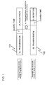
- Fig. 1 is a drawing showing a configuration example of a transmitted/received frame in the TDD scheme.
- the transmitted/received frame 101 of a base station A shown in Fig. 1 a frame is utilized for communication while being divided into DL (Downlink) transmission, guard time, and UL (Uplink) reception.
- the guard time is a time interval provided so as to prevent interference from occurring when DL transmission is switched to UL reception or vice versa.
- the ratios between DL transmission, guard time, and UL reception within a transmitted/received frame can be adjusted to optimum ratios according to the degree of congestion in the uplink and downlink traffic of each base station.
- Patent Literature 1 describes a technology that sets the angle of an antenna so as to decrease interference to adjacent cells in the TDD scheme.
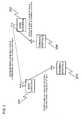
- Fig. 2 is a drawing for explaining problems in a conventional wireless communication system based on the TDD scheme.
- assumed is a case where base stations A201 and B202 are provided and terminal stations A203 and B204 communicating with the corresponding base stations are provided, as shown in Fig. 2 .
- the base station A201 receives an uplink signal from the terminal station A203 during the UL reception section, and the base station B202 transmits an downlink signal to the terminal station B204 during the DL transmission section.
- the downlink signal from the base station B202 is received by the base station A201, causing interference, and the reception quality of the uplink signal from the terminal station A203, which is a desired signal, deteriorates.
- Such interference is caused by the facts that base stations, generally built on a height with a good view, can transmit/receive radio waves to/from a distant place and that the transmission power of base stations is greater than the transmission power of terminal stations.
- Fig. 3 is a drawing showing a configuration example of a transmitted/received frame in the TDD scheme.
- base stations are generally built on a height with a good view and can transmit/receive radio waves to/from a distant place, radio waves from the base station B202 may be able to reach the base station A201 even when the base station B202 is located in a distance place.
- the signal from the base station B202 to the base station A201 reaches the base station A201 with a propagation delay corresponding to the distance between the base stations B202 and A201.
- the propagation delay is larger than the guard time, the DL transmission section of the base station B202 will overlap the UL reception section of the base station A201, causing interference and degrading the reception quality.
- the interference can be reduced by decreasing the transmission power of the interfering base station.
- the transmission power of the base station B202 which interferes with the base station A201, needs to be decreased so that the DL signal transmitted from the base station B202 does not reach the base station A201.
- such a method may reduce the communication service area served by the base station B202.
- the communication service area of the base station B202 is reduced and terminal stations outside the communication service area may not be able to communicate with the base station B202.
- a wireless communication system based on the TDD scheme has the problem that the communication service area becomes restricted when the transmission power is decreased in order to prevent interference between different base stations.
- Patent Literature 1 describes a technology in which a user device controls a radio wave transmission angle in the horizontal direction to reduce interference to other base stations. If this method is applied to a base station, the radio wave transmission angle will be controlled in the horizontal direction so as not to interfere with other base stations. However, when such a method is employed, the base station is not able to communicate with terminal stations locating in the same direction as the other base stations even if they are within the base station's own communication area.
- a base station device reduce interference signals affecting another base station while allowing the base station to communicate with a terminal station within the area of the base station in a wireless communication system based on the TDD scheme. It is an object of the present invention to provide a transmission angle control device, base station, transmission angle control method, and program that contribute to meet the need.
- a transmission angle control device in a wireless communication system based on a TDD (Time Division Duplex) scheme.
- the transmission angle control device comprises: an interference signal detection unit that detects a level of interference on a second base station caused by a signal transmitted by a first base station based on a received signal received from the second base station and that outputs the interference level as an interference information signal; and a transmission angle determining unit that adjusts a transmission angle of a signal transmitted by the first base station in a vertical direction according to the interference information signal.
- a base station comprising the transmission angle control device according to the first aspect. Further, there is provided a wireless communication system comprising the base station.
- a transmission angle control method in a wireless communication system based on a TDD (Time Division Duplex) scheme comprises: detecting a level of interference on a second base station caused by a signal transmitted by a first base station based on a received signal received from the second base station; and adjusting a transmission angle of a signal transmitted by the first base station in a vertical direction according to the interference level.
- TDD Time Division Duplex
- a program causing a computer provided in a first base station in a wireless communication system based on a TDD (Time Division Duplex) scheme to execute: detecting a level of interference on a second base station caused by a signal transmitted by the first base station based on a received signal received from the second base station; and adjusting a transmission angle of a signal transmitted by the first base station in a vertical direction according to the interference level.
- TDD Time Division Duplex
- program can be provided as a program product stored in a non-transitory computer-readable storage medium.
- the transmission angle control device, base station, transmission angle control method and program relating to the present invention it becomes possible for a first base station device to reduce interference signals affecting a second base station while allowing the first base station device to communicate with a terminal station within the area of the first base station device in a wireless communication system based on a TDD scheme.
- the present invention reduces the interference to the second base station by controlling the radio wave transmission angle of the first base station so as to point downward based on an interference information signal transmitted from the second base station.
- TDD Time Division Duplex
- an interference signal detection unit 402 receives a signal received by its own base station (the base station B202 in Fig. 2 ), demodulates an interference information signal transmitted from another base station (the base station A201 in Fig. 2 ), and outputs the result to a transmission angle determining unit 403.
- the transmission angle determining unit 403 determines the radio wave transmission angle of its own base station (the base station B202 in Fig. 2 ) based on the interference information signal, and controls the radio wave transmission angle of its own base station (the base station B202 in Fig. 2 ) by outputting transmission angle control information.
- the radio wave transmission angle of its own base station (the base station B202 in Fig. 2 ) is controlled based on the interference information signal transmitted from another base station (the base station A201 in Fig. 2 ), it becomes possible to reduce the interference to another base station (the base station A201 in Fig. 2 ) without decreasing the transmission power of its own base station (the base station B202 in Fig. 2 ).
- a transmission angle control device may be the transmission angle control device according to the first aspect.
- the transmission angle determining unit may adjust the transmission angle downward when the interference level is not less than a predetermined threshold value.
- the transmission angle determining unit may maintain the transmission angle or adjust the transmission angle upward when the interference level is less than a predetermined threshold value.
- the received signal may be a level of interference on the second base station caused by a signal transmitted by the first base station and include information indicating an interference level detected by the second base station.
- the interference signal detection unit may estimate these interference levels based on the received signal, and output estimated interference levels as the interference information signal.
- the transmission angle determining unit may adjust the transmission angle of a signal transmitted by the first base station in a vertical direction by referring to a table that associates an interference level with a transmission angle in a vertical direction.
- a base station comprising the transmission angle control device described above. Further, there is provided a wireless communication system comprising the base station and based on a TDD scheme.
- a transmission angle control method may be the transmission angle control method according to the third aspect.
- the adjusting may comprise adjusting the transmission angle downward when the interference level is not less than a predetermined threshold value.
- the adjusting may comprise maintaining the transmission angle or adjusting the transmission angle upward when the interference level is less than a predetermined threshold value.
- the received signal may be a level of interference on the second base station caused by a signal transmitted by the first base station and include information indicating an interference level detected by the second base station.
- the detecting may comprise, by deeming that a level of interference on the second base station caused by a signal transmitted by the first base station is equal to a level of interference on the first base station caused by a signal transmitted by the second base station, estimating these interference levels based on the received signal.
- Fig. 4 is a block diagram showing a configuration of a transmission angle control device 401 relating to the present exemplary embodiment.
- the transmission angle control device 401 comprises the interference signal detection unit 402 and the transmission angle determining unit 403.
- the transmission angle control device 401 is built into the base station B202 interfering with the base station A201.
- the interference signal detection unit 402 demodulates an interference information signal transmitted from another base station (the base station A201 in Fig. 2 ) and outputs the result to the transmission angle determining unit 403.
- the transmission angle determining unit 403 determines the radio wave transmission angle of its own base station (the base station B202 in Fig. 2 ) based on the interference information signal, and controls the radio wave transmission angle of its own base station (the base station B202 in Fig. 2 ) by outputting the transmission angle control information.
- the interference information signal transmitted from another base station (the base station A201 in Fig. 2 ) and demodulated by the interference signal detection unit 402 includes information on the interference to another base station, and is transmitted from another base station (the base station A201 in Fig. 2 ) according to a predetermined format. More concretely, the interference information indicates the absolute amount of the interference.
- the interference information signal transmitted from another base station (the base station A201 in Fig. 2 ) may be transmitted in a wired or wireless fashion.
- the transmission angle control information generated and outputted by the transmission angle determining unit 403 is required for having a transmission angle control unit (not shown in the drawing) in a subsequent stage electrically control the transmission angle, and indicates a transmission angle for shifting the feed phase of each transmission antenna element by a predetermined amount. More concretely, the transmission angle control information may be determined according to a table predetermined by the levels of the interference amount.
- the configuration of the present exemplary embodiment has been described above, but another base station's function of generating the interference information signal will be omitted since it is not directly related to the present invention. Further, for instance, a publicly known control unit can be used as the transmission angle control unit, but a detailed configuration will be omitted since it is also unrelated to the present invention.
- the interference information signal indicates the absolute amount of interference, however, it may be information on whether or not interference exists, or interference information divided into a predetermined plurality of interference levels.
- the transmission angle control information is determined according to a table predetermined by the levels of the interference amount, but it may be determined so that the transmission angle points downward by a predetermined angle when interference exists. Further, it may be determined so that the transmission angle is not changed or the transmission angle points upward by a predetermined angle when no interference exists.
- the transmission angle control device (not shown in the drawing) electrically controls the transmission angle, but the antenna angle may be mechanically controlled.
- Fig. 5 is a flowchart showing an operation example of the transmission angle control device 401 relating to the present exemplary embodiment. With reference to the flowchart in Fig. 5 , the operation of the transmission angle control device 401 in Fig. 4 will be described.
- the interference signal detection unit 402 upon demodulating the interference information signal, the interference signal detection unit 402 outputs the interference information signal to the transmission angle determining unit 403 (step S501).
- the transmission angle determining unit 403 determines the presence of interference based on the interference information signal (step S502). If interference exists (YES in the step S502), the transmission angle is determined (step S503) and a transmission angle control signal is outputted (step S504). Then, the demodulation of the interference information signal by the interference signal detection unit 402 (the step S501) and the processing steps thereafter are repeated.
- the transmission angle determining unit 403 determines that no interference exists (NO in the step S502)
- the operation returns to the processing of the interference signal detection unit 402, and the demodulation of the interference information signal (the step S501) and the processing steps thereafter are repeated.
- the transmission angle determining unit 403 determines the transmission angle so that the transmission angle points upward by a predetermined angle (the step S503) without determining whether or not interference exists, and outputs the transmission angle control signal (the step S504).
- the radio wave transmission angle of the first base station is controlled so as to point downward, it is not necessary to decrease the transmission power of the base station, and the communication service area can be expanded, compared with a case where the transmission power is decreased.
- the communication service area can be expanded.
- the radio wave transmission angle of the first base station (the base station B202 in Fig. 2 ) is controlled based on the interference information signal transmitted from the second base station (the base station A201 in Fig. 2 ).
- the radio wave transmission angle is controlled based on the amount of interference the first base station (the base station B202 in Fig. 2 ) receives from the second base station (the base station A201 in Fig. 2 ). This is based on a concept that the amount of interference the first base station (the base station B202 in Fig. 2 ) receives from the second base station (the base station A201 in Fig. 2 ) is equal to the amount of interference that the first base station (the base station B202 in Fig. 2 ) gives to the second base station (the base station A201 in Fig. 2 ).
- Fig. 6 is a block diagram showing a configuration example of the transmission angle control device 601 relating to the present exemplary embodiment.
- the transmission angle control device 601 comprises an interference signal detection unit 602 and a transmission angle determining unit 603.
- the interference signal detection unit 602 receives a signal received by its own base station (the base station B202 in Fig. 2 ) and detects a signal level arriving from another base station (the base station A201 in Fig. 2 ), i.e., an interference signal level. For instance, the interference signal detection unit 602 detects the interference signal level based on the correlation processing using a unique pilot signal used by another base station (the base station A201 in Fig. 2 ). The interference signal detection unit 602 outputs this interference signal level to the transmission angle determining unit 603 as the interference information signal.
- the transmission angle determining unit 603 Since the operation of the transmission angle determining unit 603 is identical to the transmission angle determining unit 403 in the transmission angle control device ( Fig. 4 ) relating to the first exemplary embodiment, the explanation will be omitted.
- the radio wave transmission angle of its own base station (the base station B202 in Fig. 2 ) can be controlled even when the interference information signal is not transmitted from another base station (the base station A201 in Fig. 2 ).
Landscapes
- Engineering & Computer Science (AREA)
- Computer Networks & Wireless Communication (AREA)
- Signal Processing (AREA)
- Quality & Reliability (AREA)
- Physics & Mathematics (AREA)
- Electromagnetism (AREA)
- Mobile Radio Communication Systems (AREA)
- Radio Transmission System (AREA)
Abstract
Description
- The present invention is based upon and claims the benefit of the priority of Japanese patent application No.
2011-139528 filed on June 23rd, 2011 - The present invention relates to a transmission angle control device, base station, transmission angle control method, and program, and particularly to a transmission angle control device, base station comprising the same, transmission angle control method, and program that control the transmission angle of a transmitted signal in a wireless communication system using a TDD (Time Division Duplex) scheme as the duplex scheme thereof.
- In a wireless communication system based on the TDD scheme, the same frequency is used for uplink and downlink communication.
Fig. 1 is a drawing showing a configuration example of a transmitted/received frame in the TDD scheme. In the TDD scheme, as the transmitted/receivedframe 101 of a base station A shown inFig. 1 , a frame is utilized for communication while being divided into DL (Downlink) transmission, guard time, and UL (Uplink) reception. Here, the guard time is a time interval provided so as to prevent interference from occurring when DL transmission is switched to UL reception or vice versa. The ratios between DL transmission, guard time, and UL reception within a transmitted/received frame can be adjusted to optimum ratios according to the degree of congestion in the uplink and downlink traffic of each base station. - Patent Literature 1 describes a technology that sets the angle of an antenna so as to decrease interference to adjacent cells in the TDD scheme.
- Japanese Patent Kohyo Publication No.
JP-P2005-525041A - The following analysis is given by the present inventor.
- As shown in
Fig. 1 , when the transmitted/receivedframe 101 of the base station A and a transmitted/receivedframe 102 of a base station B have different ratios of DL transmission and UL reception, interference from the base station B to the base station A occurs due to the fact that a DL transmission section of the base station B overlaps a UL reception section of the base station A, degrading the quality of the UL reception at the base station A. -
Fig. 2 is a drawing for explaining problems in a conventional wireless communication system based on the TDD scheme. Here, as an example, assumed is a case where base stations A201 and B202 are provided and terminal stations A203 and B204 communicating with the corresponding base stations are provided, as shown inFig. 2 . - During the overlapping section shown in
Fig. 1 between the DL transmission section of the base station B202 and the UL reception section of the base station A201, the base station A201 receives an uplink signal from the terminal station A203 during the UL reception section, and the base station B202 transmits an downlink signal to the terminal station B204 during the DL transmission section. At this time, the downlink signal from the base station B202 is received by the base station A201, causing interference, and the reception quality of the uplink signal from the terminal station A203, which is a desired signal, deteriorates. Such interference is caused by the facts that base stations, generally built on a height with a good view, can transmit/receive radio waves to/from a distant place and that the transmission power of base stations is greater than the transmission power of terminal stations. - On the other hand, even when the base stations A201 and B202 have the same ratio of DL transmission and UL reception in a transmitted/received frame, interference from the base station B202 to the base station A201 may similarly occur, degrading the reception quality.
- This will be explained with reference to
Fig. 3. Fig. 3 is a drawing showing a configuration example of a transmitted/received frame in the TDD scheme. As stated above, since base stations are generally built on a height with a good view and can transmit/receive radio waves to/from a distant place, radio waves from the base station B202 may be able to reach the base station A201 even when the base station B202 is located in a distance place. - At this time, the signal from the base station B202 to the base station A201 reaches the base station A201 with a propagation delay corresponding to the distance between the base stations B202 and A201. As a result, even in the case where the base stations have the same ratio between DL transmission and UL reception in a transmitted/received frame, if the propagation delay is larger than the guard time, the DL transmission section of the base station B202 will overlap the UL reception section of the base station A201, causing interference and degrading the reception quality.
- As a countermeasure against the problem above, the interference can be reduced by decreasing the transmission power of the interfering base station. For instance, in
Fig. 2 , the transmission power of the base station B202, which interferes with the base station A201, needs to be decreased so that the DL signal transmitted from the base station B202 does not reach the base station A201. - However, such a method may reduce the communication service area served by the base station B202. In other words, by decreasing the transmission power of the base station B202, the communication service area of the base station B202 is reduced and terminal stations outside the communication service area may not be able to communicate with the base station B202.
- As described, a wireless communication system based on the TDD scheme has the problem that the communication service area becomes restricted when the transmission power is decreased in order to prevent interference between different base stations.
- Patent Literature 1 describes a technology in which a user device controls a radio wave transmission angle in the horizontal direction to reduce interference to other base stations. If this method is applied to a base station, the radio wave transmission angle will be controlled in the horizontal direction so as not to interfere with other base stations. However, when such a method is employed, the base station is not able to communicate with terminal stations locating in the same direction as the other base stations even if they are within the base station's own communication area.
- Therefore, there is a need in the art to have a base station device reduce interference signals affecting another base station while allowing the base station to communicate with a terminal station within the area of the base station in a wireless communication system based on the TDD scheme. It is an object of the present invention to provide a transmission angle control device, base station, transmission angle control method, and program that contribute to meet the need.
- According to a first aspect of the present invention, there is provided a transmission angle control device in a wireless communication system based on a TDD (Time Division Duplex) scheme. The transmission angle control device comprises: an interference signal detection unit that detects a level of interference on a second base station caused by a signal transmitted by a first base station based on a received signal received from the second base station and that outputs the interference level as an interference information signal; and a transmission angle determining unit that adjusts a transmission angle of a signal transmitted by the first base station in a vertical direction according to the interference information signal.
- According to a second aspect of the present invention, there is provided a base station comprising the transmission angle control device according to the first aspect. Further, there is provided a wireless communication system comprising the base station.
- According to a third aspect of the present invention, there is provided a transmission angle control method in a wireless communication system based on a TDD (Time Division Duplex) scheme. The transmission angle control method comprises: detecting a level of interference on a second base station caused by a signal transmitted by a first base station based on a received signal received from the second base station; and adjusting a transmission angle of a signal transmitted by the first base station in a vertical direction according to the interference level.
- According to a fourth aspect of the present invention, there is provided a program causing a computer provided in a first base station in a wireless communication system based on a TDD (Time Division Duplex) scheme to execute: detecting a level of interference on a second base station caused by a signal transmitted by the first base station based on a received signal received from the second base station; and adjusting a transmission angle of a signal transmitted by the first base station in a vertical direction according to the interference level.
- Further, the program can be provided as a program product stored in a non-transitory computer-readable storage medium.
- According to the transmission angle control device, base station, transmission angle control method and program relating to the present invention, it becomes possible for a first base station device to reduce interference signals affecting a second base station while allowing the first base station device to communicate with a terminal station within the area of the first base station device in a wireless communication system based on a TDD scheme.
-
-
Fig. 1 is a drawing showing a configuration example of a transmitted/received frame in a TDD scheme. -
Fig. 2 is a drawing for explaining problems in a wireless communication system based on a TDD scheme. -
Fig. 3 is a drawing showing a configuration example of a transmitted/received frame in a TDD scheme. -
Fig. 4 is a block diagram showing a configuration of a transmission angle control device relating to a first exemplary embodiment. -
Fig. 5 is a flowchart showing an operation example of the transmission angle control device relating to the first exemplary embodiment. -
Fig. 6 is a block diagram showing a configuration of a transmission angle control device relating to a second exemplary embodiment. - First, a summary of the present invention will be given. Note that drawing reference signs in the summary are illustrated examples solely for facilitating understanding and are not intended to limit the present invention to illustrated examples.
- When a first base station used in a wireless communication system using a TDD (Time Division Duplex) scheme as the duplex scheme thereof interferes with a second base station, the present invention reduces the interference to the second base station by controlling the radio wave transmission angle of the first base station so as to point downward based on an interference information signal transmitted from the second base station.
- With reference to
Fig. 4 , an interferencesignal detection unit 402 receives a signal received by its own base station (the base station B202 inFig. 2 ), demodulates an interference information signal transmitted from another base station (the base station A201 inFig. 2 ), and outputs the result to a transmissionangle determining unit 403. The transmissionangle determining unit 403 determines the radio wave transmission angle of its own base station (the base station B202 inFig. 2 ) based on the interference information signal, and controls the radio wave transmission angle of its own base station (the base station B202 inFig. 2 ) by outputting transmission angle control information. - As described, since the radio wave transmission angle of its own base station (the base station B202 in
Fig. 2 ) is controlled based on the interference information signal transmitted from another base station (the base station A201 inFig. 2 ), it becomes possible to reduce the interference to another base station (the base station A201 inFig. 2 ) without decreasing the transmission power of its own base station (the base station B202 inFig. 2 ). - In the present invention, the following modes are possible.
- A transmission angle control device may be the transmission angle control device according to the first aspect.
- The transmission angle determining unit may adjust the transmission angle downward when the interference level is not less than a predetermined threshold value.
- The transmission angle determining unit may maintain the transmission angle or adjust the transmission angle upward when the interference level is less than a predetermined threshold value.
- The received signal may be a level of interference on the second base station caused by a signal transmitted by the first base station and include information indicating an interference level detected by the second base station.
- By deeming that a level of interference on the second base station caused by a signal transmitted by the first base station is equal to a level of interference on the first base station caused by a signal transmitted by the second base station, the interference signal detection unit may estimate these interference levels based on the received signal, and output estimated interference levels as the interference information signal.
- The transmission angle determining unit may adjust the transmission angle of a signal transmitted by the first base station in a vertical direction by referring to a table that associates an interference level with a transmission angle in a vertical direction.
- There is provided a base station comprising the transmission angle control device described above. Further, there is provided a wireless communication system comprising the base station and based on a TDD scheme.
- A transmission angle control method may be the transmission angle control method according to the third aspect.
- The adjusting may comprise adjusting the transmission angle downward when the interference level is not less than a predetermined threshold value.
- The adjusting may comprise maintaining the transmission angle or adjusting the transmission angle upward when the interference level is less than a predetermined threshold value.
- The received signal may be a level of interference on the second base station caused by a signal transmitted by the first base station and include information indicating an interference level detected by the second base station.
- The detecting may comprise, by deeming that a level of interference on the second base station caused by a signal transmitted by the first base station is equal to a level of interference on the first base station caused by a signal transmitted by the second base station, estimating these interference levels based on the received signal.
- Transmission angle control relating to a first exemplary embodiment will be described with reference to the drawings.
Fig. 4 is a block diagram showing a configuration of a transmissionangle control device 401 relating to the present exemplary embodiment. With reference toFig. 4 , the transmissionangle control device 401 comprises the interferencesignal detection unit 402 and the transmissionangle determining unit 403. In the example ofFig. 2 , the transmissionangle control device 401 is built into the base station B202 interfering with the base station A201. - The interference
signal detection unit 402 demodulates an interference information signal transmitted from another base station (the base station A201 inFig. 2 ) and outputs the result to the transmissionangle determining unit 403. The transmissionangle determining unit 403 determines the radio wave transmission angle of its own base station (the base station B202 inFig. 2 ) based on the interference information signal, and controls the radio wave transmission angle of its own base station (the base station B202 inFig. 2 ) by outputting the transmission angle control information. - The interference information signal transmitted from another base station (the base station A201 in
Fig. 2 ) and demodulated by the interferencesignal detection unit 402 includes information on the interference to another base station, and is transmitted from another base station (the base station A201 inFig. 2 ) according to a predetermined format. More concretely, the interference information indicates the absolute amount of the interference. The interference information signal transmitted from another base station (the base station A201 inFig. 2 ) may be transmitted in a wired or wireless fashion. - The transmission angle control information generated and outputted by the transmission
angle determining unit 403 is required for having a transmission angle control unit (not shown in the drawing) in a subsequent stage electrically control the transmission angle, and indicates a transmission angle for shifting the feed phase of each transmission antenna element by a predetermined amount. More concretely, the transmission angle control information may be determined according to a table predetermined by the levels of the interference amount. - The configuration of the present exemplary embodiment has been described above, but another base station's function of generating the interference information signal will be omitted since it is not directly related to the present invention. Further, for instance, a publicly known control unit can be used as the transmission angle control unit, but a detailed configuration will be omitted since it is also unrelated to the present invention.
- Further, in the present exemplary embodiment, the interference information signal indicates the absolute amount of interference, however, it may be information on whether or not interference exists, or interference information divided into a predetermined plurality of interference levels.
- Further, the transmission angle control information is determined according to a table predetermined by the levels of the interference amount, but it may be determined so that the transmission angle points downward by a predetermined angle when interference exists. Further, it may be determined so that the transmission angle is not changed or the transmission angle points upward by a predetermined angle when no interference exists.
- Further, the transmission angle control device (not shown in the drawing) electrically controls the transmission angle, but the antenna angle may be mechanically controlled.
-
Fig. 5 is a flowchart showing an operation example of the transmissionangle control device 401 relating to the present exemplary embodiment. With reference to the flowchart inFig. 5 , the operation of the transmissionangle control device 401 inFig. 4 will be described. - With reference to
Fig. 5 , upon demodulating the interference information signal, the interferencesignal detection unit 402 outputs the interference information signal to the transmission angle determining unit 403 (step S501). The transmissionangle determining unit 403 determines the presence of interference based on the interference information signal (step S502). If interference exists (YES in the step S502), the transmission angle is determined (step S503) and a transmission angle control signal is outputted (step S504). Then, the demodulation of the interference information signal by the interference signal detection unit 402 (the step S501) and the processing steps thereafter are repeated. - Meanwhile, when the transmission
angle determining unit 403 determines that no interference exists (NO in the step S502), the operation returns to the processing of the interferencesignal detection unit 402, and the demodulation of the interference information signal (the step S501) and the processing steps thereafter are repeated. - Further, in the case where the transmission angle points upward by a predetermined angle when no interference exists, the transmission
angle determining unit 403 determines the transmission angle so that the transmission angle points upward by a predetermined angle (the step S503) without determining whether or not interference exists, and outputs the transmission angle control signal (the step S504). - According to the present exemplary embodiment, the following effects can be obtained.
- As the first effect, when a first base station is interfering with a second base station, since the radio wave transmission angle of the first base station is controlled so as to point downward, it is not necessary to decrease the transmission power of the base station, and the communication service area can be expanded, compared with a case where the transmission power is decreased.
- As the second effect, when the first base station is not interfering with the second base station, since the radio wave transmission angle of the first base station is controlled so as to point upward, the communication service area can be expanded.
- A transmission angle control device relating to a second exemplary embodiment will be described with reference to the drawings. In the first exemplary embodiment, the radio wave transmission angle of the first base station (the base station B202 in
Fig. 2 ) is controlled based on the interference information signal transmitted from the second base station (the base station A201 inFig. 2 ). Meanwhile, in the present exemplary embodiment, the radio wave transmission angle is controlled based on the amount of interference the first base station (the base station B202 inFig. 2 ) receives from the second base station (the base station A201 inFig. 2 ). This is based on a concept that the amount of interference the first base station (the base station B202 inFig. 2 ) receives from the second base station (the base station A201 inFig. 2 ) is equal to the amount of interference that the first base station (the base station B202 inFig. 2 ) gives to the second base station (the base station A201 inFig. 2 ). -
Fig. 6 is a block diagram showing a configuration example of the transmissionangle control device 601 relating to the present exemplary embodiment. With reference toFig. 6 , the transmissionangle control device 601 comprises an interferencesignal detection unit 602 and a transmissionangle determining unit 603. - The interference
signal detection unit 602 receives a signal received by its own base station (the base station B202 inFig. 2 ) and detects a signal level arriving from another base station (the base station A201 inFig. 2 ), i.e., an interference signal level. For instance, the interferencesignal detection unit 602 detects the interference signal level based on the correlation processing using a unique pilot signal used by another base station (the base station A201 inFig. 2 ). The interferencesignal detection unit 602 outputs this interference signal level to the transmissionangle determining unit 603 as the interference information signal. - Since the operation of the transmission
angle determining unit 603 is identical to the transmissionangle determining unit 403 in the transmission angle control device (Fig. 4 ) relating to the first exemplary embodiment, the explanation will be omitted. - According to the transmission
angle control device 601 of the present exemplary embodiment, the radio wave transmission angle of its own base station (the base station B202 inFig. 2 ) can be controlled even when the interference information signal is not transmitted from another base station (the base station A201 inFig. 2 ). - Further, each disclosure of the prior art documents such as Patent Literature listed above is incorporated herein in its entirety by reference thereto. It should be noted that other objects, features and aspects of the present invention will become apparent in the entire disclosure and that modifications may be done without departing the gist and scope of the present invention as disclosed herein and claimed as appended herewith.
Also it should be noted that any combination of the disclosed and/or claimed elements, matters and/or items may fall under the modifications aforementioned. -
- 101, 102: transmitted/received frame
- 201: base station A
- 202: base station B
- 203: terminal station A
- 204: terminal station B
- 301, 302: transmitted/received frame
- 401: transmission angle control device
- 402: interference signal detection unit
- 403: transmission angle determining unit
- 601: transmission angle control device
- 602: interference signal detection unit
- 603: transmission angle determining unit
Claims (17)
- A transmission angle control device in a wireless communication system based on a TDD (Time Division Duplex) scheme, the device comprising:an interference signal detection unit that detects a level of interference on a second base station caused by a signal transmitted by a first base station based on a received signal received from the second base station and that outputs the interference level as an interference information signal; anda transmission angle determining unit that adjusts a transmission angle of a signal transmitted by the first base station in a vertical direction according to the interference information signal.
- The transmission angle control device according to claim 1, wherein the transmission angle determining unit adjusts the transmission angle downward when the interference level is not less than a predetermined threshold value.
- The transmission angle control device according to claim 1 or 2, wherein the transmission angle determining unit maintains the transmission angle or adjusts the transmission angle upward when the interference level is less than a predetermined threshold value.
- The transmission angle control device according to any one of claims 1 to 3, wherein the received signal is a level of interference on the second base station caused by a signal transmitted by the first base station and includes information indicating an interference level detected by the second base station.
- The transmission angle control device according to any one of claims 1 to 3, wherein, by deeming that a level of interference on the second base station caused by a signal transmitted by the first base station is equal to a level of interference on the first base station caused by a signal transmitted by the second base station, the interference signal detection unit estimates these interference levels based on the received signal, and outputs estimated interference levels as the interference information signal.
- The transmission angle control device according to any one of claims 1 to 5, wherein the transmission angle determining unit adjusts the transmission angle of a signal transmitted by the first base station in a vertical direction by referring to a table that associates an interference level with a transmission angle in a vertical direction.
- The first base station comprising the transmission angle control device according to any one of claims 1 to 6.
- A transmission angle control method in a wireless communication system based on a TDD (Time Division Duplex) scheme, the method comprising:detecting a level of interference on a second base station caused by a signal transmitted by a first base station based on a received signal received from the second base station; andadjusting a transmission angle of a signal transmitted by the first base station in a vertical direction according to the interference level.
- The transmission angle control method according to claim 8, wherein the adjusting comprises adjusting the transmission angle downward when the interference level is not less than a predetermined threshold value.
- The transmission angle control method according to claim 8 or 9, wherein the adjusting comprises maintaining the transmission angle or adjusting the transmission angle upward when the interference level is less than a predetermined threshold value.
- The transmission angle control method according to any one of claims 8 to 10, wherein the received signal is a level of interference on the second base station caused by a signal transmitted by the first base station and includes information indicating an interference level detected by the second base station.
- The transmission angle control method according to any one of claims 8 to 10, wherein, the detecting comprises, by deeming that a level of interference on the second base station caused by a signal transmitted by the first base station is equal to a level of interference on the first base station caused by a signal transmitted by the second base station, estimating these interference levels based on the received signal.
- A program, causing a computer provided in a first base station in a wireless communication system based on a TDD (Time Division Duplex) scheme to execute:detecting a level of interference on a second base station caused by a signal transmitted by the first base station based on a received signal received from the second base station; andadjusting a transmission angle of a signal transmitted by the first base station in a vertical direction according to the interference level.
- The program according to claim 13, wherein the adjusting comprises adjusting the transmission angle downward when the interference level is not less than a predetermined threshold value.
- The program according to claim 13 or 14, wherein the adjusting comprises maintaining the transmission angle or adjusting the transmission angle upward when the interference level is less than a predetermined threshold value.
- The program according to any one of claims 13 to 15, wherein the received signal is a level of interference on the second base station caused by a signal transmitted by the first base station and includes information indicating an interference level detected by the second base station.
- The program according to any one of claims 13 to 15, wherein the detecting comprises, by deeming that a level of interference on the second base station caused by a signal transmitted by the first base station is equal to a level of interference on the first base station caused by a signal transmitted by the second base station, estimating these interference levels based on the received signal.
Applications Claiming Priority (2)
| Application Number | Priority Date | Filing Date | Title |
|---|---|---|---|
| JP2011139528 | 2011-06-23 | ||
| PCT/JP2012/065960 WO2012176867A1 (en) | 2011-06-23 | 2012-06-22 | Transmission angle control device, base station, transmission angle control method, and program |
Publications (2)
| Publication Number | Publication Date |
|---|---|
| EP2725720A1 true EP2725720A1 (en) | 2014-04-30 |
| EP2725720A4 EP2725720A4 (en) | 2014-12-31 |
Family
ID=47422695
Family Applications (1)
| Application Number | Title | Priority Date | Filing Date |
|---|---|---|---|
| EP12802053.4A Withdrawn EP2725720A4 (en) | 2011-06-23 | 2012-06-22 | Transmission angle control device, base station, transmission angle control method, and program |
Country Status (5)
| Country | Link |
|---|---|
| US (1) | US9520958B2 (en) |
| EP (1) | EP2725720A4 (en) |
| JP (1) | JP5936143B2 (en) |
| CN (1) | CN103620983B (en) |
| WO (1) | WO2012176867A1 (en) |
Families Citing this family (1)
| Publication number | Priority date | Publication date | Assignee | Title |
|---|---|---|---|---|
| CN107293857B (en) * | 2017-06-30 | 2021-05-14 | 维沃移动通信有限公司 | Method, mobile terminal and computer-readable storage medium for processing signal interference |
Family Cites Families (21)
| Publication number | Priority date | Publication date | Assignee | Title |
|---|---|---|---|---|
| JPH11215538A (en) | 1998-01-26 | 1999-08-06 | Matsushita Electric Ind Co Ltd | Mobile station device, base station device, and mobile communication system |
| JPH11252624A (en) | 1998-03-02 | 1999-09-17 | Fujitsu Ltd | Synchronization control method of radio base station in digital mobile communication |
| US6549529B1 (en) | 1999-02-01 | 2003-04-15 | Lucent Technologies Inc. | System and method for controlling antenna downtilt/uptilt in a wireless communication network |
| US6487416B1 (en) * | 1999-07-30 | 2002-11-26 | Qwest Communications International, Inc. | Method and system for controlling antenna downtilt in a CDMA network |
| JP2001358651A (en) * | 2000-06-16 | 2001-12-26 | Yrp Mobile Telecommunications Key Tech Res Lab Co Ltd | Mobile communication system, base station unit and transmission power control method |
| MXPA04011049A (en) | 2002-05-07 | 2005-09-20 | Ipr Licensing Inc | Antenna adaptation in a time division duplexing system. |
| ATE422800T1 (en) * | 2003-12-31 | 2009-02-15 | Ericsson Telefon Ab L M | DYNAMIC ANTENNA CONTROL |
| CN1264257C (en) | 2003-12-31 | 2006-07-12 | 复旦大学 | Bicavity series full solidifying fly second laser |
| DE602005015721D1 (en) * | 2005-06-15 | 2009-09-10 | Alcatel Lucent | Uplink interference coordination method in monofrequency networks, base station and mobile network therefor |
| JP4718395B2 (en) | 2006-08-14 | 2011-07-06 | 株式会社エヌ・ティ・ティ・ドコモ | Base station apparatus and antenna pattern control method |
| KR100951382B1 (en) * | 2006-09-07 | 2010-04-08 | 삼성전자주식회사 | Method and apparatus for eliminating interference of uplink received signal in time division duplex system |
| JP2008113136A (en) * | 2006-10-30 | 2008-05-15 | Kyocera Corp | Wireless communication system, base station, base control station, and communication area control method |
| WO2009038507A1 (en) * | 2007-09-18 | 2009-03-26 | Telefonaktiebolaget Lm Ericsson (Publ) | A tdd testing device |
| KR20090094752A (en) | 2008-03-03 | 2009-09-08 | 엘지전자 주식회사 | Method of transmitting interference information signal in wireless communication system |
| CN101541012A (en) * | 2008-03-21 | 2009-09-23 | 夏普株式会社 | Interference overload indication generation method, interference overload indication triggering method, interference overload indication method and base station |
| JP2011018966A (en) | 2009-07-07 | 2011-01-27 | Hitachi Ltd | Radio base station of mobile data communication system |
| JP2011071907A (en) | 2009-09-28 | 2011-04-07 | Kyocera Corp | Base station, and base station system |
| JP5322906B2 (en) | 2009-11-30 | 2013-10-23 | 三菱電機株式会社 | Base station apparatus and scheduling method |
| WO2011071425A1 (en) * | 2009-12-08 | 2011-06-16 | Telefonaktiebolaget L M Ericsson (Publ) | Method and arrangement for energy consumption balancing between base stations in a communication system |
| US8385900B2 (en) * | 2009-12-09 | 2013-02-26 | Reverb Networks | Self-optimizing networks for fixed wireless access |
| WO2012150881A1 (en) * | 2011-05-03 | 2012-11-08 | Telefonaktiebolaget Lm Ericsson (Publ) | Methods and arrangements in a wireless communication system |
-
2012
- 2012-06-22 WO PCT/JP2012/065960 patent/WO2012176867A1/en not_active Ceased
- 2012-06-22 US US14/127,481 patent/US9520958B2/en active Active
- 2012-06-22 JP JP2013521624A patent/JP5936143B2/en not_active Expired - Fee Related
- 2012-06-22 CN CN201280028576.8A patent/CN103620983B/en active Active
- 2012-06-22 EP EP12802053.4A patent/EP2725720A4/en not_active Withdrawn
Also Published As
| Publication number | Publication date |
|---|---|
| CN103620983B (en) | 2017-05-24 |
| CN103620983A (en) | 2014-03-05 |
| JPWO2012176867A1 (en) | 2015-02-23 |
| JP5936143B2 (en) | 2016-06-15 |
| US20140112214A1 (en) | 2014-04-24 |
| WO2012176867A1 (en) | 2012-12-27 |
| US9520958B2 (en) | 2016-12-13 |
| EP2725720A4 (en) | 2014-12-31 |
Similar Documents
| Publication | Publication Date | Title |
|---|---|---|
| US10149252B2 (en) | Methods and apparatus related to interference management when sharing downlink bandwidth between wide area network usage and peer to peer signaling | |
| CN102655650B (en) | Method and equipment for positioning far-end interference base station | |
| EP3206313B1 (en) | Method and system for detecting idle channel in wireless communication system | |
| EP2421307A1 (en) | Method, apparatus and device for selecting relay user and allocating downlink resource | |
| EP4410016B1 (en) | Intelligent interference mitigation for time division duplexing broadband networks | |
| US8351955B2 (en) | Method and device for determining antenna cooperation set, method and device for determining base station cooperation set | |
| US10212675B2 (en) | Method, terminal device and wireless network node for matching uplink coverage area and downlink coverage area | |
| CN108259112B (en) | A time slot-based base station interference cancellation method and device | |
| CN102655652A (en) | Method and equipment for detecting far-end interference | |
| US9391592B2 (en) | Methods and systems for dynamically adjusting frequency offsets for mitigating interference | |
| KR102151597B1 (en) | Methods and apparatus for efficient co-existence of macro and small cells | |
| US20100159844A1 (en) | Radio Communication Device and Radio Communication Method | |
| EP2725720A1 (en) | Transmission angle control device, base station, transmission angle control method, and program | |
| JP7462404B2 (en) | COMMUNICATION DEVICE, CONTROL METHOD, AND PROGRAM | |
| KR20140145092A (en) | Method and its apparatus for transmitting consecutive signals | |
| JP7102278B2 (en) | Electronic device and communication method | |
| US20160135135A1 (en) | Method and apparatus for communication for coexisting with wireless-lan in non-licensed band | |
| Cai et al. | Spectrum sharing between random geometric networks | |
| WO2017036529A1 (en) | Techniques to reduce guard period overhead in wireless networks | |
| US20150055520A1 (en) | Base station and communication control method | |
| JP4791345B2 (en) | Base station and slot allocation method | |
| US20130273927A1 (en) | Base station and frequency band allocation method | |
| US10038512B1 (en) | Methods and apparatus for controlling frame timing and/or duration in a communications system | |
| JP5646193B2 (en) | Communication terminal and transmission power control method thereof | |
| JP4172811B2 (en) | Wireless device and communication control method |
Legal Events
| Date | Code | Title | Description |
|---|---|---|---|
| PUAI | Public reference made under article 153(3) epc to a published international application that has entered the european phase |
Free format text: ORIGINAL CODE: 0009012 |
|
| 17P | Request for examination filed |
Effective date: 20140116 |
|
| AK | Designated contracting states |
Kind code of ref document: A1 Designated state(s): AL AT BE BG CH CY CZ DE DK EE ES FI FR GB GR HR HU IE IS IT LI LT LU LV MC MK MT NL NO PL PT RO RS SE SI SK SM TR |
|
| DAX | Request for extension of the european patent (deleted) | ||
| A4 | Supplementary search report drawn up and despatched |
Effective date: 20141127 |
|
| RIC1 | Information provided on ipc code assigned before grant |
Ipc: H04B 7/06 20060101ALI20141121BHEP Ipc: H04B 17/00 20060101ALI20141121BHEP Ipc: H04W 16/28 20090101ALI20141121BHEP Ipc: H04B 7/10 20060101AFI20141121BHEP |
|
| 17Q | First examination report despatched |
Effective date: 20180614 |
|
| STAA | Information on the status of an ep patent application or granted ep patent |
Free format text: STATUS: THE APPLICATION HAS BEEN WITHDRAWN |
|
| 18W | Application withdrawn |
Effective date: 20180829 |