EP2725546A1 - Display processing method and apparatus - Google Patents
Display processing method and apparatus Download PDFInfo
- Publication number
- EP2725546A1 EP2725546A1 EP13189724.1A EP13189724A EP2725546A1 EP 2725546 A1 EP2725546 A1 EP 2725546A1 EP 13189724 A EP13189724 A EP 13189724A EP 2725546 A1 EP2725546 A1 EP 2725546A1
- Authority
- EP
- European Patent Office
- Prior art keywords
- section
- cross
- time
- transformation processing
- processing
- Prior art date
- Legal status (The legal status is an assumption and is not a legal conclusion. Google has not performed a legal analysis and makes no representation as to the accuracy of the status listed.)
- Granted
Links
Images




Classifications
-
- G—PHYSICS
- G06—COMPUTING OR CALCULATING; COUNTING
- G06T—IMAGE DATA PROCESSING OR GENERATION, IN GENERAL
- G06T3/00—Geometric image transformations in the plane of the image
- G06T3/14—Transformations for image registration, e.g. adjusting or mapping for alignment of images
- G06T3/147—Transformations for image registration, e.g. adjusting or mapping for alignment of images using affine transformations
-
- G—PHYSICS
- G16—INFORMATION AND COMMUNICATION TECHNOLOGY [ICT] SPECIALLY ADAPTED FOR SPECIFIC APPLICATION FIELDS
- G16H—HEALTHCARE INFORMATICS, i.e. INFORMATION AND COMMUNICATION TECHNOLOGY [ICT] SPECIALLY ADAPTED FOR THE HANDLING OR PROCESSING OF MEDICAL OR HEALTHCARE DATA
- G16H50/00—ICT specially adapted for medical diagnosis, medical simulation or medical data mining; ICT specially adapted for detecting, monitoring or modelling epidemics or pandemics
- G16H50/50—ICT specially adapted for medical diagnosis, medical simulation or medical data mining; ICT specially adapted for detecting, monitoring or modelling epidemics or pandemics for simulation or modelling of medical disorders
-
- G—PHYSICS
- G06—COMPUTING OR CALCULATING; COUNTING
- G06T—IMAGE DATA PROCESSING OR GENERATION, IN GENERAL
- G06T19/00—Manipulating three-dimensional [3D] models or images for computer graphics
- G06T19/20—Editing of three-dimensional [3D] images, e.g. changing shapes or colours, aligning objects or positioning parts
-
- A—HUMAN NECESSITIES
- A61—MEDICAL OR VETERINARY SCIENCE; HYGIENE
- A61B—DIAGNOSIS; SURGERY; IDENTIFICATION
- A61B2576/00—Medical imaging apparatus involving image processing or analysis
- A61B2576/02—Medical imaging apparatus involving image processing or analysis specially adapted for a particular organ or body part
- A61B2576/023—Medical imaging apparatus involving image processing or analysis specially adapted for a particular organ or body part for the heart
Definitions
- This invention relates to a display processing technique.
- measurement apparatuses for the medical service such as an ultrasonic diagnostic equipment, Magnetic Resonance Imaging (MRI) apparatus, Computed Tomography (CT) scan apparatus and the like are used to directly measure information of organs such as cross sections of the cardiac muscle of the heart.
- the information of the cross sections of the heart is 2-dimensional image data, typically.
- both of them represent the behaviors of the cardiac muscle, however, data formats of both of them are different each other, both of them can be displayed on right and left in order to compare the results of them. However, it is not easy to display both of them as time goes by while arranging both of them in appropriate positions to superimpose them.
- the measurement is performed by putting, by a doctor, a probe that emits the ultrasonic onto the breast or the abdomen of the patient. Therefore, there are problems that strain arises in the measured image and that the cross section is not fixed and the images of the cross section fluctuate.
- an object of this invention is to provide a technique for displaying properly superimposed data of image data outputted by a measurement equipment and image data of a generated 3-dimensional geometric model.
- a display processing method relating to this invention includes: (A) accepting designation of two first control points in a model cross section that is a cross section of a generated model of an object, wherein each of the two first control points corresponds to either of two second control points in an input image that is obtained by photographing a cross section of the object for a reference time; (B) first performing a first transformation processing that includes expansion or reduction for the model cross section for the reference time so that a position of a second control point for the reference time is identical to a position of a corresponding first control point; (C) first superimposing the input image for the reference time and the model cross section after the first transformation processing to display a first superimposition result; (D) second performing a second transformation processing for a second model cross section for a second time that is a time after the reference time, so that a position of one of two second control points in an input image for the second time is identical to a position of a corresponding first control point in the second model cross section, and another first control point in the second model cross section
- FIG. 1 illustrates a functional block diagram of a display processing apparatus relating to an embodiment of this invention.
- the display processing apparatus 100 is connected to a measurement equipment 200 such as the ultrasonic diagnosis equipment, MRI apparatus, CT scan apparatus or the like, and is also connected to an input unit 140 and display unit 150.
- the display processing apparatus 100 includes an image data storage unit 110 that stores image data received from the measurement equipment 200, a geometric model data storage unit 120 stores data of the 3-dimensional geometric model, a data storage unit 130 that stores data during a processing, and a processing unit 160 that execute the processing relating to this embodiment.
- the image data storage unit 110 stores image data for plural frames that are outputted, for example, by the measurement equipment 200 and arranged at intervals of a predetermined time.
- FIG. 2 illustrates image data for one frame, which is generated by the ultrasonic echo emitted by the ultrasonic diagnosis equipment.
- the image data illustrated in FIG. 2 represents a cross section of the heart, however, because a doctor fixes the probe, the position of the cross section is not always fixed in the space due to the effect of the breathing and/or the doctor himself. Moreover, because of the lens effect of the ultrasonic, the position of the cardiac muscle in the image is not always positioned in the true position of the cardiac muscle.
- the geometric model data storage unit 120 stores geometric model data (e.g. tetrahedral element data) in a time-series, which is generated for a period for one beat of the heart, in case of the heart.
- the geometric model data includes coordinate values for each vertex of the tetrahedral elements used to identify the shape, element information, a physical value of each element, and the like.
- the processing unit 160 includes a time-step adjustment unit 161, cross section generator 162, control point setting unit 163, transformation processing unit 164 and superimposition processing unit 165.
- the control point setting unit 163 may include a control point generator 1631.
- the time-step adjustment unit 161 extracts data of the geometric models so as to synchronize with the image frame, for example, because the number of frames for the image in the period for one beat of the heart is different from the number of time-steps for the generated geometric models.
- the cross section generator 162 In response to an instruction from the user, the cross section generator 162 generates data of the cross section, which corresponds to the cross section of the heart, which is represented in the image stored in the image data storage unit 110, from data of the geometric model.
- control point setting unit 163 sets two points on the image for each frame and corresponding two points on the cross sections of the geometric models, as control points.
- the control point generator 1631 automatically extracts points corresponding to the annulus from the image in case of the heart. Therefore, when the control points are set to the annulus, the control point generator 1631 sets the control points.
- the control points are set to other points, the user designates the control points.
- the transformation processing unit 164 performs at least either of rotation, translation, expansion and reduction for data of the cross sections of the geometric models, for example, as necessary. For example, when the image data outputted by the ultrasonic diagnosis equipment or the like is superimposed on the generated geometric model data, the transformation processing unit 164 performs the transformation processing so that the geometric model data can be superimposed on the image data.
- the transformation processing unit 164 also performs at least either of the rotation and translation for data for time after the reference time, in addition to the transformation processing for data for the reference time (e.g. initial time).
- the superimposition processing unit 165 superimposes data of the cross section of the geometric model after the transformation processing by the transformation processing unit 164 on the image data for each frame, and causes the display unit 150 to displays the superimposed data.
- the time-step adjustment unit 161 of the processing unit 160 performs a processing to adjust the time-steps of the images and geometric models from a frame interval of the images stored in the image data storage unit 110 and a time interval of the geometric models stored in the geometric model data storage unit 120 ( FIG. 3 : step S1).
- a processing to adjust the time-steps of the images and geometric models from a frame interval of the images stored in the image data storage unit 110 and a time interval of the geometric models stored in the geometric model data storage unit 120 ( FIG. 3 : step S1).
- data of the geometric models is extracted so that the interval of the extracted geometric models becomes identical with the frame interval of the images, for example.
- This processing will be depicted schematically in FIG. 4 .
- the number of geometric models is greater than the number of frames of the images.
- the extracted geometric model is used as the geometric model to be superimposed.
- data of the geometric model at the same time exists, however, if data of the geometric model at the same time do not exist, data of the geometric model at the same time is generated by interpolating the geometric models before and after that time, for example.
- the geometric model at that timing may be extracted without the interpolation.
- the image frames may be extracted so that the interval of the extracted images becomes identical the timing of the geometric model.
- the cross section generator 162 of the processing unit 160 prompts the user to designate a cross section corresponding to the cross section of an object, which is represented by the image data, and when the user's designation for the cross section of the geometric model is accepted (step S3), the cross section generator 162 generates data of the cross sections of the geometric models according to the instruction, and stores the data of the cross sections into the data storage unit 130, for example (step S5).
- the image of the ultrasonic echo includes movement of organs on the plane, however, when considering that no fluctuation at the photographing is included in a perpendicular direction to the image plane, it is considered that the image of the ultrasonic echo is data in a fixed space. Therefore, for example, a corresponding cross section in the geometric model at the reference time (e.g. start or initial time) is identified, and the corresponding cross section in the geometric models is fixed to perform a following processing.
- a corresponding cross section in the geometric model at the reference time e.g. start or initial time
- the cross-section view of the parasternal long-axis and left-side and the cross-section view of the parasternal short-axis and left-side e.g. aortic level, apex level, papillary muscle level, mitral valve level or the like
- the cross-section view of the apical four-chamber, the cross-section view of the apical two-chamber, the transesophageal view or the like are photographed mostly, so the pertinent cross section is designated for the geometric model.
- the processing itself to generate data of the cross section of the geometric model is a processing that has been executed conventionaly (e.g. a function in AVS/Express supplied by AVS Co. Ltd., Paraview supplied by Kitware Inc. or the like), so the detailed explanation is omitted here.
- data of the cross section of the geometric model is generated as illustrated in FIG. 5 .
- the cross section data is generated.
- the cross section data is expressed by triangular elements, for example.
- control point setting unit 163 performs a processing to set two corresponding control points for each of the cross sections of the geometric models and the images (step S7).
- the control point generator 1631 identifies control points corresponding to the annulus from the image of each frame. For example, see Yoko Eto, et. al., "Automated Mitral Annular Tracking: A Novel Method for Evaluating Mitral Annular Motion Using Two-dimensional Echocardiography", Journal of the American Society of Echocardiography, pp.306-312, Volume 18 Number 4, (2005 ).
- control points Index11 and Index12 are identified as illustrated in FIG. 6 .
- the user maydesignate points individually.
- a control point Index21corresponding to the control point Index11 is set according to the user's designation
- a control point Index22 corresponding to the control Index12 is set according to the user's designation.
- the transformation processing unit 164 performs a first transformation processing that includes at least one of the translation, rotation and scaling (e.g. expansion and/or reduction) so that the positions of the corresponding control points become identical, for the cross section of the geometric model to be superimposed for each time, and stores the processing results into the data storage unit 130 (step S9).
- a first transformation processing that includes at least one of the translation, rotation and scaling (e.g. expansion and/or reduction) so that the positions of the corresponding control points become identical, for the cross section of the geometric model to be superimposed for each time, and stores the processing results into the data storage unit 130 (step S9).
- the coordinates of the control point Index11 in the image at the reference time is (x I_Index11 , y I_Index11 ), the coordinates of the control point Index12 is (x I_Index12 , y I_Index12 ), the coordinates of the control point Index21 in the cross section of the geometric model at the reference time is (x P_Index21 , y P_Index21 ), and the coordinates of the control point Index22 in the cross section of the geometric model at the reference time is (x P_Index22 , y P_Index22 ).
- the translation and rotation are performed so that the position of the control point Index21 becomes identical to the position of the control point Index11, and the position of the control point Index22 becomes the position of the control point Index12. Because the calculation for this transformation processing is well-known, the detailed explanation is omitted.
- the first transformation processing is a basic processing for the superimposition
- the first transformation processing is also performed for the cross section of the geometric model to be superimposed for each time other than the reference time.
- the scaling may be performed for the cross section of the geometric model to be superimposed for each time other than the referencetime, and the translation and the rotation may not beperformed at this stage.
- the scaling may also be performed immediately before the processing for making the positions of the control points identical and the like.
- the superimposition processing unit 165 generates display data by superimposing the image and the cross section after the first transformation processing for the same time to output the generated the display data to the display unit 150 (step S11).
- the superimposing display as illustrated in FIG. 8 is performed.
- the image data in order to make it easy to view the image data, only contours of the cross section of the geometric model to be superimposed are displayed.
- the user may select how to display the inside of the contours, and for example, it may be painted over in a predetermined color.
- the processing unit 160 determines whether or not an event for the processing end is detected such as the processing end is instructed by the user (step S13). When the event for the processing end is detected, the processing ends.
- the transformation processing unit 164 identifies image data at a next time in the image data storage unit 110 and cross section data in the geometric model to be superimposed at the next time in the data storage unit 130 (step S15). Then, the transformation processing unit 164 performs a second transformation processing to execute at least one of the translation and rotation for the identified cross section of the geometric model to be superimposed so that one control point (e. g. control point Index22) is fixed on a corresponding control point (e. g. control point Index12) in the image and the other control point (e.g. control point Index21) is on a straight line passing through two control points in the image (step S17).
- one control point e. g. control point Index22
- a corresponding control point e. g. control point Index12
- the other control point e.g. control point Index21
- the scaling is also executed each time in order to make positions of the corresponding control points of the image and cross section of the geometric model to be superimposed for each time after the reference time identical.
- the scaling is carried out for the cross sections for each time after the reference time in the first transformation processing by using the scale parameters at the reference time, and in the second transformation processing, at least either of the translation and rotation is performed for the cross sections for each time after the reference time.
- the first transformation processing by the scale parameters may be included in the second transformation processing.
- the translation is performed so as to make positions of the control point Index12 in the image and corresponding control point Index22 in the cross section X of the geometric model to be superimposed for the same time identical.
- the control point Index21 in the cross section X of the geometric model to be superimposed is rotated by an angle ⁇ using the control point Index22 as the center of the rotation so that the control point Index21 is on a straight line passing through the control points Index11 and Index12.
- the control point Index11 is not placed on the control point Index21, however, they are arranged almost at the same position.
- the straight line passing through the two control points Index11 and Index12 has the same direction of the straight line passing through the two control points Index21 and Index22.
- the processing shifts to the step S11.
- the superimposition processing unit 165 superimposes the cross section data after the second transformation processing and image data to generate data to display the superimposition result.
- the image obtained from the measurement equipment 200 and data of the same cross section of the geometric model can be superimposed and displayed so as to make it easy to understand the state.
- the transformation processing may be performed for the image.
- the reference is the cross section of the geometric model to be superimposed.
- the first transformation processing may not be performed at the step S9 for the cross sections after the reference time, and the first transformation processing and the second transformation processing may be performed at the step S17. Furthermore, in such a case, when the control points such as the annulus are automatically extracted from the image, this processing maybe executed after the step S15 for the images of the frames after the reference time.
- the aforementioned display processing apparatus 100 is a computer device as illustrated in FIG.10 . That is, a memory 2501 (storage device), a CPU 2503 (processor), a hard disk drive (HDD) 2505, a display controller 2507 connected to a display device 2509, a drive device 2513 for a removable disk 2511, an input device 2515, and a communication controller 2517 for connection with a network are connected through a bus 2519 as illustrated in FIG.10 .
- An operating system (OS) and an application program for carrying out the foregoing processing in the embodiment, are stored in the HDD 2505, and when executed by the CPU 2503, they are read out from the HDD 2505 to the memory 2501.
- OS operating system
- an application program for carrying out the foregoing processing in the embodiment
- the CPU 2503 controls the display controller 2507, the communication controller 2517, and the drive device 2513, and causes them to perform predetermined operations. Moreover, intermediate processing data is stored in the memory 2501, and if necessary, it is stored in the HDD 2505.
- the application program to realize the aforementioned functions is stored in the computer-readable, non-transitory removable disk 2511 and distributed, and then it is installed into the HDD 2505 from the drive device 2513. It may be installed into the HDD 2505 via the network such as the Internet and the communication controller 2517.
- the hardware such as the CPU 2503 and the memory 2501, the OS and the application programs systematically cooperate with each other, so that various functions as described above in details are realized.
- a display processing method relating to a first aspect of the embodiments includes: (A) accepting designation of two second control points in a second cross section in a model of an object for a reference time, wherein each of the two second control points corresponds to either of two first control points in an image of a corresponding first cross section of the object for the reference time; (B) performing a first transformation processing that includes expansion or reduction for the second cross section of the model of the object for the reference time so that the positions of the first control point and corresponding second control point are identical or overlap each other; (C) superimposing the image of the corresponding first cross section for the reference time and the second cross section of the model of the object after the first transformation processing to display the superimposition result; (D) performing a second transformation processing for a second cross section of a model of the object for a second time that is a time after the reference time so that a position of one of first control points in an image of a cross section of the object for the second time is identical to a position of a corresponding second control point in
- the display processing method relating to the first aspect of the embodiment may further include: extracting images of the cross sections of the object or data of the models of the object for the same time according to a time interval of the image of the cross section of the object or a time interval of data of the models of the object. For example, data whose time interval is shorter may be extracted in conformity with data whose time interval is longer.
- data of the second cross section in the model of the obj ect may be generated for each time, and the first transformation processing may be performed for the second cross section of the model of the object for each time.
- the second transformation processing it is possible to execute the second transformation processing at high speed.
- the second cross section of the model of the object for each time after the reference time only the expansion or reduction may be executed.
- the aforementioned expansion or reduction may be performed as part of the second transformation processing instead of the first transformation processing.
- a display processing method relating to a second aspect of the embodiments includes: (A) accepting designation of two second control points in a second cross section in a model of an object for a reference time, wherein each of the two second control points corresponds to either of two first control points in an image of a corresponding first cross section of the object for the reference time; (B) performing a first transformation processing that includes expansion or reduction for the image of the corresponding first cross section of the object so that the positions of the first control point and corresponding second control point are identical or overlap each other; (C) superimposing the image of the corresponding first cross section for the reference time after the first transformation processing and the second cross section of the model of the object to display the superimposition result; (D) performing a second transformation processing for an image of a cross section of the obj ect for a second time that is a time after the reference time so that a position of one of second control points in a second cross section of a model of the object for the second time is identical to a position of a corresponding
- the image of the cross section of the object may be handled as a main processing target.
Landscapes
- Engineering & Computer Science (AREA)
- Public Health (AREA)
- Medical Informatics (AREA)
- Health & Medical Sciences (AREA)
- Theoretical Computer Science (AREA)
- General Physics & Mathematics (AREA)
- Physics & Mathematics (AREA)
- Pathology (AREA)
- Databases & Information Systems (AREA)
- General Health & Medical Sciences (AREA)
- Primary Health Care (AREA)
- Architecture (AREA)
- Computer Graphics (AREA)
- Computer Hardware Design (AREA)
- General Engineering & Computer Science (AREA)
- Software Systems (AREA)
- Epidemiology (AREA)
- Data Mining & Analysis (AREA)
- Biomedical Technology (AREA)
- Magnetic Resonance Imaging Apparatus (AREA)
- Apparatus For Radiation Diagnosis (AREA)
- Ultra Sonic Daignosis Equipment (AREA)
- Measuring And Recording Apparatus For Diagnosis (AREA)
- Image Processing (AREA)
- Controls And Circuits For Display Device (AREA)
- Image Analysis (AREA)
Abstract
Description
- This invention relates to a display processing technique.
- Recently, various analyses for human organs, especially, heart are performed. Specifically, blood is outputted by the cardiac muscle that contracts according to electric signals. The numerical analysis for reproducing suchphenomena is carriedout. Then, according to results of the numerical analysis, behaviors of the cardiac muscle are displayed by using 3-dimensional computer graphics technique.
- On the other hand, in the medical scene, measurement apparatuses for the medical service such as an ultrasonic diagnostic equipment, Magnetic Resonance Imaging (MRI) apparatus, Computed Tomography (CT) scan apparatus and the like are used to directly measure information of organs such as cross sections of the cardiac muscle of the heart. The information of the cross sections of the heart is 2-dimensional image data, typically.
- Because both of them represent the behaviors of the cardiac muscle, however, data formats of both of them are different each other, both of them can be displayed on right and left in order to compare the results of them. However, it is not easy to display both of them as time goes by while arranging both of them in appropriate positions to superimpose them. Especially, in the ultrasonic diagnosis using the ultrasonic diagnosis equipment, the measurement is performed by putting, by a doctor, a probe that emits the ultrasonic onto the breast or the abdomen of the patient. Therefore, there are problems that strain arises in the measured image and that the cross section is not fixed and the images of the cross section fluctuate.
- Therefore, as one aspect, an object of this invention is to provide a technique for displaying properly superimposed data of image data outputted by a measurement equipment and image data of a generated 3-dimensional geometric model.
- A display processing method relating to this invention includes: (A) accepting designation of two first control points in a model cross section that is a cross section of a generated model of an object, wherein each of the two first control points corresponds to either of two second control points in an input image that is obtained by photographing a cross section of the object for a reference time; (B) first performing a first transformation processing that includes expansion or reduction for the model cross section for the reference time so that a position of a second control point for the reference time is identical to a position of a corresponding first control point; (C) first superimposing the input image for the reference time and the model cross section after the first transformation processing to display a first superimposition result; (D) second performing a second transformation processing for a second model cross section for a second time that is a time after the reference time, so that a position of one of two second control points in an input image for the second time is identical to a position of a corresponding first control point in the second model cross section, and another first control point in the second model cross section is on a straight line that passes through the two second control points in the input image for the second time; and (E) second superimposing the input image for the second time and the second model cross section after the second transformation processing to display a second superimposition result.
- Reference will now be made, by way of example, to the accompanying Drawings, in which:
-
FIG. 1 is a functional block diagram of a display processing apparatus relating to an embodiment; -
FIG. 2 is a diagram depicting an example of an image of a cross section of the heart; -
FIG. 3 is a diagram depicting a processing flow of a processing relating to the embodiment; -
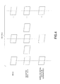
FIG. 4 is a diagram schematically depicting a time-step adjustment processing; -
FIG. 5 is a diagram depicting an example of a cross section of a geometric model; -
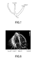
FIG. 6 is a diagram depicting a setting example of control points for the image; -
FIG. 7 is a diagram depicting a setting example of control points for the cross section of the geometric model; -
FIG. 8 is a diagram depicting an example of initial superimposition display; -
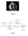
FIG. 9A is a diagram depicting an example of a result of a first transformation processing; -
FIG. 9B is a diagram depicting an example of a state in an initial stage of a second transformation processing; -
FIG. 9C is a diagram depicting an example of a state in a final state of the second transformation processing; and -
FIG. 10 is a functional block diagram of a computer. -
FIG. 1 illustrates a functional block diagram of a display processing apparatus relating to an embodiment of this invention. Thedisplay processing apparatus 100 is connected to ameasurement equipment 200 such as the ultrasonic diagnosis equipment, MRI apparatus, CT scan apparatus or the like, and is also connected to aninput unit 140 anddisplay unit 150. Moreover, thedisplay processing apparatus 100 includes an imagedata storage unit 110 that stores image data received from themeasurement equipment 200, a geometric modeldata storage unit 120 stores data of the 3-dimensional geometric model, adata storage unit 130 that stores data during a processing, and aprocessing unit 160 that execute the processing relating to this embodiment. - The image
data storage unit 110 stores image data for plural frames that are outputted, for example, by themeasurement equipment 200 and arranged at intervals of a predetermined time. As an example,FIG. 2 illustrates image data for one frame, which is generated by the ultrasonic echo emitted by the ultrasonic diagnosis equipment. The image data illustrated inFIG. 2 represents a cross section of the heart, however, because a doctor fixes the probe, the position of the cross section is not always fixed in the space due to the effect of the breathing and/or the doctor himself. Moreover, because of the lens effect of the ultrasonic, the position of the cardiac muscle in the image is not always positioned in the true position of the cardiac muscle. In this embodiment, as one example, a case will be explained in which the image data outputted by the ultrasonic diagnosis equipment is superimposed with the generated geometric model data, however, of course, it is also possible to apply this embodiment to a case in which image data outputted by the MRI apparatus or CT scan apparatus is superimposed with the generated geometric model. - The geometric model
data storage unit 120 stores geometric model data (e.g. tetrahedral element data) in a time-series, which is generated for a period for one beat of the heart, in case of the heart. The geometric model data includes coordinate values for each vertex of the tetrahedral elements used to identify the shape, element information, a physical value of each element, and the like. - The
processing unit 160 includes a time-step adjustment unit 161,cross section generator 162, controlpoint setting unit 163,transformation processing unit 164 andsuperimposition processing unit 165. Moreover, the controlpoint setting unit 163 may include acontrol point generator 1631. - The time-
step adjustment unit 161 extracts data of the geometric models so as to synchronize with the image frame, for example, because the number of frames for the image in the period for one beat of the heart is different from the number of time-steps for the generated geometric models. - In response to an instruction from the user, the
cross section generator 162 generates data of the cross section, which corresponds to the cross section of the heart, which is represented in the image stored in the imagedata storage unit 110, from data of the geometric model. - For example, in response to an instruction from the user, the control
point setting unit 163 sets two points on the image for each frame and corresponding two points on the cross sections of the geometric models, as control points. Thecontrol point generator 1631 automatically extracts points corresponding to the annulus from the image in case of the heart. Therefore, when the control points are set to the annulus, thecontrol point generator 1631 sets the control points. When the control points are set to other points, the user designates the control points. - The
transformation processing unit 164 performs at least either of rotation, translation, expansion and reduction for data of the cross sections of the geometric models, for example, as necessary. For example, when the image data outputted by the ultrasonic diagnosis equipment or the like is superimposed on the generated geometric model data, thetransformation processing unit 164 performs the transformation processing so that the geometric model data can be superimposed on the image data. Thetransformation processing unit 164 also performs at least either of the rotation and translation for data for time after the reference time, in addition to the transformation processing for data for the reference time (e.g. initial time). - The
superimposition processing unit 165 superimposes data of the cross section of the geometric model after the transformation processing by thetransformation processing unit 164 on the image data for each frame, and causes thedisplay unit 150 to displays the superimposed data. - Next, processing contents of the
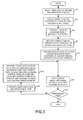
display processing apparatus 100 will be explained by usingFIG. 3 to FIG. 9C . - First, the time-
step adjustment unit 161 of theprocessing unit 160 performs a processing to adjust the time-steps of the images and geometric models from a frame interval of the images stored in the imagedata storage unit 110 and a time interval of the geometric models stored in the geometric model data storage unit 120 (FIG. 3 : step S1). Typically, because the frame interval of the images is longer that the time interval of the geometric models, data of the geometric models is extracted so that the interval of the extracted geometric models becomes identical with the frame interval of the images, for example. This processing will be depicted schematically inFIG. 4 . For example, when the image data and the geometric model data are arranged for one beat of the heart, the number of geometric models is greater than the number of frames of the images. Then, by extracting data of the geometric model at the same time (depicted by vertical dotted line inFIG. 4 ) as each frame of the image, the extracted geometric model is used as the geometric model to be superimposed. In an example ofFIG. 4 , data of the geometric model at the same time exists, however, if data of the geometric model at the same time do not exist, data of the geometric model at the same time is generated by interpolating the geometric models before and after that time, for example. However, when the difference between timings is little, the geometric model at that timing may be extracted without the interpolation. Moreover, when the interval of the image frames is shorter, the image frames may be extracted so that the interval of the extracted images becomes identical the timing of the geometric model. - Next, the
cross section generator 162 of theprocessing unit 160 prompts the user to designate a cross section corresponding to the cross section of an object, which is represented by the image data, and when the user's designation for the cross section of the geometric model is accepted (step S3), thecross section generator 162 generates data of the cross sections of the geometric models according to the instruction, and stores the data of the cross sections into thedata storage unit 130, for example (step S5). - The image of the ultrasonic echo includes movement of organs on the plane, however, when considering that no fluctuation at the photographing is included in a perpendicular direction to the image plane, it is considered that the image of the ultrasonic echo is data in a fixed space. Therefore, for example, a corresponding cross section in the geometric model at the reference time (e.g. start or initial time) is identified, and the corresponding cross section in the geometric models is fixed to perform a following processing.
- When the heart is photographed by the ultrasonic echo, typically, the cross-section view of the parasternal long-axis and left-side and the cross-section view of the parasternal short-axis and left-side (e.g. aortic level, apex level, papillary muscle level, mitral valve level or the like), the cross-section view of the apical four-chamber, the cross-section view of the apical two-chamber, the transesophageal view or the like are photographed mostly, so the pertinent cross section is designated for the geometric model.
- The processing itself to generate data of the cross section of the geometric model is a processing that has been executed conventionaly (e.g. a function in AVS/Express supplied by AVS Co. Ltd., Paraview supplied by Kitware Inc. or the like), so the detailed explanation is omitted here.
- For example, data of the cross section of the geometric model is generated as illustrated in
FIG. 5 . Here, for each of the geometric models to be superimposed, which were extracted at the step S1, the cross section data is generated. The cross section data is expressed by triangular elements, for example. - Next, the control
point setting unit 163 performs a processing to set two corresponding control points for each of the cross sections of the geometric models and the images (step S7). As described above, in case of the heart, it is possible to automatically extract the annulus, so when the user designates the annulus as the control point from theinput unit 140, thecontrol point generator 1631 identifies control points corresponding to the annulus from the image of each frame. For example, see Yoko Eto, et. al., "Automated Mitral Annular Tracking: A Novel Method for Evaluating Mitral Annular Motion Using Two-dimensional Echocardiography", Journal of the American Society of Echocardiography, pp.306-312, Volume 18 Number 4, (2005). - In case of the image as illustrated in
FIG. 2 , control points Index11 and Index12 are identified as illustrated inFIG. 6 . However, in case of using the annulus as the control points or using other points as the control points, the usermaydesignate points individually. Furthermore, as schematically illustrated inFIG. 7 , on the cross section of the geometric model, a control point Index21corresponding to the control point Index11 is set according to the user's designation, and a control point Index22 corresponding to the control Index12 is set according to the user's designation. When the control points are set at vertexes of the triangular elements on the cross section of the geometric model at the reference time, the same vertexes of the same triangular elements will be processed as being selected at each time that is later than the reference time. However, for each of the cross sections of the geometric models to be superimposed, the control points may be set according to the user's designation. - After that, the
transformation processing unit 164 performs a first transformation processing that includes at least one of the translation, rotation and scaling (e.g. expansion and/or reduction) so that the positions of the corresponding control points become identical, for the cross section of the geometric model to be superimposed for each time, and stores the processing results into the data storage unit 130 (step S9). - More specifically, the coordinates of the control point Index11 in the image at the reference time is (xI_Index11, yI_Index11), the coordinates of the control point Index12 is (xI_Index12, yI_Index12), the coordinates of the control point Index21 in the cross section of the geometric model at the reference time is (xP_Index21, yP_Index21), and the coordinates of the control point Index22 in the cross section of the geometric model at the reference time is (xP_Index22, yP_Index22).
- In this case, the scale parameters Sx and Sy are calculated as follows:


- After expanding or reducing the size by using such scale parameters, the translation and rotation are performed so that the position of the control point Index21 becomes identical to the position of the control point Index11, and the position of the control point Index22 becomes the position of the control point Index12. Because the calculation for this transformation processing is well-known, the detailed explanation is omitted.
- Because the first transformation processing is a basic processing for the superimposition, the first transformation processing is also performed for the cross section of the geometric model to be superimposed for each time other than the reference time. However, only the scaling may be performed for the cross section of the geometric model to be superimposed for each time other than the referencetime, and the translation and the rotation may not beperformed at this stage. Furthermore, the scaling may also be performed immediately before the processing for making the positions of the control points identical and the like.
- Then, the
superimposition processing unit 165 generates display data by superimposing the image and the cross section after the first transformation processing for the same time to output the generated the display data to the display unit 150 (step S11). - For example, at the reference time, the superimposing display as illustrated in
FIG. 8 is performed. As illustrated inFIG. 7 , in order to make it easy to view the image data, only contours of the cross section of the geometric model to be superimposed are displayed. The user may select how to display the inside of the contours, and for example, it may be painted over in a predetermined color. - Then, the
processing unit 160 determines whether or not an event for the processing end is detected such as the processing end is instructed by the user (step S13). When the event for the processing end is detected, the processing ends. - On the other hand, when the processing does not end, the
transformation processing unit 164 identifies image data at a next time in the imagedata storage unit 110 and cross section data in the geometric model to be superimposed at the next time in the data storage unit 130 (step S15). Then, thetransformation processing unit 164 performs a second transformation processing to execute at least one of the translation and rotation for the identified cross section of the geometric model to be superimposed so that one control point (e. g. control point Index22) is fixed on a corresponding control point (e. g. control point Index12) in the image and the other control point (e.g. control point Index21) is on a straight line passing through two control points in the image (step S17). - Because the size of the annulus changes according to the movement of the heart, when the annulus is used as the control point, the scaling is also executed each time in order to make positions of the corresponding control points of the image and cross section of the geometric model to be superimposed for each time after the reference time identical. In this embodiment, in order to simplify the processing, the scaling is carried out for the cross sections for each time after the reference time in the first transformation processing by using the scale parameters at the reference time, and in the second transformation processing, at least either of the translation and rotation is performed for the cross sections for each time after the reference time. However, the first transformation processing by the scale parameters may be included in the second transformation processing.
- For example, in the first transformation processing, when the cross sectionX of the geometric model to be superimposed is arranged as illustrated in
FIG. 9A , the translation is performed so as to make positions of the control point Index12 in the image and corresponding control point Index22 in the cross section X of the geometric model to be superimposed for the same time identical. Moreover, the control point Index21 in the cross section X of the geometric model to be superimposed is rotated by an angle θ using the control point Index22 as the center of the rotation so that the control point Index21 is on a straight line passing through the control points Index11 and Index12. Then, as illustrated inFIG. 9C , the control point Index11 is not placed on the control point Index21, however, they are arranged almost at the same position. Moreover, the straight line passing through the two control points Index11 and Index12 has the same direction of the straight line passing through the two control points Index21 and Index22. - After that, the processing shifts to the step S11. In other words, the
superimposition processing unit 165 superimposes the cross section data after the second transformation processing and image data to generate data to display the superimposition result. - By repeating such a processing, the image obtained from the
measurement equipment 200 and data of the same cross section of the geometric model can be superimposed and displayed so as to make it easy to understand the state. - Although the embodiment of this invention was explained above, this invention is not limited to the embodiment. For example, the functional block diagram is a mere example, and a different program module configuration may be employed. Moreover, as for the processing flow, as long as the processing result does not change, the turns of the steps maybe exchanged or plural steps maybe executed inparallel.
- For example, an example was explained in which the first transformation processing and the second transformation processing are performed for the cross section of the geometric model to be superimposed, the transformation processing may be performed for the image. At that time, the reference is the cross section of the geometric model to be superimposed.
- Moreover, the first transformation processing may not be performed at the step S9 for the cross sections after the reference time, and the first transformation processing and the second transformation processing may be performed at the step S17. Furthermore, in such a case, when the control points such as the annulus are automatically extracted from the image, this processing maybe executed after the step S15 for the images of the frames after the reference time.
- In addition, the aforementioned
display processing apparatus 100 is a computer device as illustrated inFIG.10 . That is, a memory 2501 (storage device), a CPU 2503 (processor), a hard disk drive (HDD) 2505, a display controller 2507 connected to adisplay device 2509, adrive device 2513 for aremovable disk 2511, aninput device 2515, and acommunication controller 2517 for connection with a network are connected through abus 2519 as illustrated inFIG.10 . An operating system (OS) and an application program for carrying out the foregoing processing in the embodiment, are stored in theHDD 2505, and when executed by theCPU 2503, they are read out from theHDD 2505 to thememory 2501. As the need arises, theCPU 2503 controls the display controller 2507, thecommunication controller 2517, and thedrive device 2513, and causes them to perform predetermined operations. Moreover, intermediate processing data is stored in thememory 2501, and if necessary, it is stored in theHDD 2505. In this embodiment of this technique, the application program to realize the aforementioned functions is stored in the computer-readable, non-transitoryremovable disk 2511 and distributed, and then it is installed into theHDD 2505 from thedrive device 2513. It may be installed into theHDD 2505 via the network such as the Internet and thecommunication controller 2517. In the computer as stated above, the hardware such as theCPU 2503 and thememory 2501, the OS and the application programs systematically cooperate with each other, so that various functions as described above in details are realized. - The embodiments of this invention are outlined as follows:
- A display processing method relating to a first aspect of the embodiments includes: (A) accepting designation of two second control points in a second cross section in a model of an object for a reference time, wherein each of the two second control points corresponds to either of two first control points in an image of a corresponding first cross section of the object for the reference time; (B) performing a first transformation processing that includes expansion or reduction for the second cross section of the model of the object for the reference time so that the positions of the first control point and corresponding second control point are identical or overlap each other; (C) superimposing the image of the corresponding first cross section for the reference time and the second cross section of the model of the object after the first transformation processing to display the superimposition result; (D) performing a second transformation processing for a second cross section of a model of the object for a second time that is a time after the reference time so that a position of one of first control points in an image of a cross section of the object for the second time is identical to a position of a corresponding second control point in a second cross section after the expansion or reduction for the second time, and another second control point in the second cross section after the expansion or reduction for the second time, which corresponds to the other first control point, is on a straight line passing through the two control points in the image of the cross section of the object for the second time; and (E) superimposing the image of the cross section of the object for the second time and the second cross section of the object after the second transformation processing.
- According to this method, even after the second time, it is possible to superimpose the cross section of the model of the object and the image of the cross section of the object, appropriately with the simplified processing (i.e. the second transformation processing).
- Moreover, the display processing method relating to the first aspect of the embodiment may further include: extracting images of the cross sections of the object or data of the models of the object for the same time according to a time interval of the image of the cross section of the object or a time interval of data of the models of the object. For example, data whose time interval is shorter may be extracted in conformity with data whose time interval is longer.
- Furthermore, in the aforementioned first transformation processing, data of the second cross section in the model of the obj ect may be generated for each time, and the first transformation processing may be performed for the second cross section of the model of the object for each time. Thus, it is possible to execute the second transformation processing at high speed. As for the second cross section of the model of the object for each time after the reference time, only the expansion or reduction may be executed. The aforementioned expansion or reduction may be performed as part of the second transformation processing instead of the first transformation processing.
- A display processing method relating to a second aspect of the embodiments includes: (A) accepting designation of two second control points in a second cross section in a model of an object for a reference time, wherein each of the two second control points corresponds to either of two first control points in an image of a corresponding first cross section of the object for the reference time; (B) performing a first transformation processing that includes expansion or reduction for the image of the corresponding first cross section of the object so that the positions of the first control point and corresponding second control point are identical or overlap each other; (C) superimposing the image of the corresponding first cross section for the reference time after the first transformation processing and the second cross section of the model of the object to display the superimposition result; (D) performing a second transformation processing for an image of a cross section of the obj ect for a second time that is a time after the reference time so that a position of one of second control points in a second cross section of a model of the object for the second time is identical to a position of a corresponding first control point in a cross section after the expansion or reduction for the second time, and another first control point in the image of the cross section of the object for the second time, which corresponds to the other second control point, is on a straight line passing through the two second control points in the second cross section for the second time; and (E) superimposing the image of the cross section of the obj ect after the second transformation processing for the second time and the second cross section of the object.
- Thus, the image of the cross section of the object may be handled as a main processing target.
- Incidentally, it is possible to create a program causing a computer to execute the aforementioned processing, and such a program is stored in a computer readable storage medium or storage device such as a flexible disk, CD-ROM, DVD-ROM, magneto-optic disk, a semiconductor memory, and hard disk. In addition, the intermediate processing result is temporarily stored in a storage device such as a main memory or the like.
- All examples and conditional language recited herein are intended for pedagogical purposes to aid the reader in understanding the invention and the concepts contributed by the inventor to furthering the art, and are to be construed as being without limitation to such specifically recited examples and conditions, nor does the organization of such examples in the specification relate to a showing of the superiority and inferiority of the invention. Although the embodiments of the present inventions have been described in detail, it should be understood that the various changes, substitutions, and alterations could be made hereto without departing from the spirit and scope of the invention.
Claims (5)
- A display processing method, comprising:accepting designation of two first control points in a model cross section that is a cross section of a generated model of an obj ect, wherein each of the two first control points corresponds to either of two second control points in an input image that is obtained by photographing a cross section of the object for a reference time;first performing a first transformation processing that includes expansion or reduction for the model cross section for the reference time so that a position of a second control point for the reference time is identical to a position of a corresponding first control point;first superimposing the input image for the reference time and the model cross section after the first transformation processing to display a first superimposition result;second performing a second transformation processing for a second model cross section for a second time that is a time after the reference time, for which the expansion or reduction was performed, so that a position of one of two second control points in an input image for the second time is identical to a position of a corresponding first control point in the second model cross section after the first transformation processing, and another first control point in the second model cross section after the first transformation processing is on a straight line that passes through the two second control points in the input image for the second time; andsecond superimposing the input image for the second time and the second model cross section after the second transformation processing to display a second superimposition result.
- The display processing method as set forth in claim 1, further comprising:extracting input images or model cross sections according to an input interval of the input images or an interval of generation of models of the objects.
- The display processing method as set forth in claim 2, wherein the first performing comprises:generating a model cross section for each time; andperforming the first transformation processing for the model cross section for each time.
- An image processing program for causing a computer to execute the display processing method set forth in any one of claims 1 to 3.
- An image processing apparatus, comprising:a memory; anda processor configured to use the memory and execute a process, the process comprising:accepting designation of two first control points in a model cross section that is a cross section of a generated model of an object, wherein each of the two first control points corresponds to either of two second control points in an input image that is obtained by photographing a cross section of the object for a reference time;first performing a first transformation processing that includes expansion or reduction for the model cross section for the reference time so that a position of a second control point for the reference time is identical to a position of a corresponding first control point;first superimposing the input image for the reference time and the model cross sectionafter the first transformation processing to display a first superimposition result;second performing a second transformation processing for a second model cross section for a second time that is a time after the reference time, for which the expansion or reduction was performed, so that a position of one of two second control points in an input image for the second time is identical to a position of a corresponding first control point in the second model cross section after the first transformation processing, and another first control point in the second model cross section after the first transformation processing is on a straight line that passes through the two second control points in the input image for the second time; andsecond superimposing the input image for the second time and the second model cross section after the second transformation processing to display a second superimposition result.
Applications Claiming Priority (1)
| Application Number | Priority Date | Filing Date | Title |
|---|---|---|---|
| JP2012234051A JP6135901B2 (en) | 2012-10-23 | 2012-10-23 | Display processing program, display processing method, and display processing apparatus |
Publications (2)
| Publication Number | Publication Date |
|---|---|
| EP2725546A1 true EP2725546A1 (en) | 2014-04-30 |
| EP2725546B1 EP2725546B1 (en) | 2020-09-02 |
Family
ID=49474264
Family Applications (1)
| Application Number | Title | Priority Date | Filing Date |
|---|---|---|---|
| EP13189724.1A Active EP2725546B1 (en) | 2012-10-23 | 2013-10-22 | Display processing method and apparatus |
Country Status (3)
| Country | Link |
|---|---|
| US (1) | US10163529B2 (en) |
| EP (1) | EP2725546B1 (en) |
| JP (1) | JP6135901B2 (en) |
Families Citing this family (1)
| Publication number | Priority date | Publication date | Assignee | Title |
|---|---|---|---|---|
| WO2019134757A1 (en) * | 2018-01-08 | 2019-07-11 | Brainlab Ag | Optimizing an atlas |
Citations (6)
| Publication number | Priority date | Publication date | Assignee | Title |
|---|---|---|---|---|
| US20050213849A1 (en) * | 2001-07-30 | 2005-09-29 | Accuimage Diagnostics Corp. | Methods and systems for intensity matching of a plurality of radiographic images |
| US20070014452A1 (en) * | 2003-12-01 | 2007-01-18 | Mitta Suresh | Method and system for image processing and assessment of a state of a heart |
| US20090161938A1 (en) * | 2006-08-14 | 2009-06-25 | University Of Maryland, Baltimore | Quantitative real-time 4d stress test analysis |
| US20100111389A1 (en) * | 2007-12-06 | 2010-05-06 | Siemens Medical Solutions Usa, Inc. | System and method for planning and guiding percutaneous procedures |
| US20110091087A1 (en) * | 2009-10-20 | 2011-04-21 | Siemens Corporation | Three-dimensional esophageal reconstruction |
| EP2369553A2 (en) * | 2010-03-26 | 2011-09-28 | Fujitsu Limited | Three-dimensional template transformation method and apparatus |
Family Cites Families (8)
| Publication number | Priority date | Publication date | Assignee | Title |
|---|---|---|---|---|
| JPH07284014A (en) * | 1995-02-15 | 1995-10-27 | Olympus Optical Co Ltd | Image handling equipment |
| US5810007A (en) * | 1995-07-26 | 1998-09-22 | Associates Of The Joint Center For Radiation Therapy, Inc. | Ultrasound localization and image fusion for the treatment of prostate cancer |
| US6106466A (en) * | 1997-04-24 | 2000-08-22 | University Of Washington | Automated delineation of heart contours from images using reconstruction-based modeling |
| US6556695B1 (en) * | 1999-02-05 | 2003-04-29 | Mayo Foundation For Medical Education And Research | Method for producing high resolution real-time images, of structure and function during medical procedures |
| JP4704630B2 (en) * | 2001-09-14 | 2011-06-15 | アロカ株式会社 | Ultrasonic panoramic image forming device |
| JP5173303B2 (en) * | 2007-07-27 | 2013-04-03 | 株式会社東芝 | Medical image processing apparatus and medical image diagnostic apparatus |
| JP4746068B2 (en) * | 2008-03-28 | 2011-08-10 | 一史 浦澤 | Image analysis apparatus and image analysis method |
| JP5498181B2 (en) * | 2010-01-29 | 2014-05-21 | 株式会社東芝 | Medical image acquisition device |
-
2012
- 2012-10-23 JP JP2012234051A patent/JP6135901B2/en not_active Expired - Fee Related
-
2013
- 2013-10-22 EP EP13189724.1A patent/EP2725546B1/en active Active
- 2013-10-23 US US14/061,387 patent/US10163529B2/en active Active
Patent Citations (6)
| Publication number | Priority date | Publication date | Assignee | Title |
|---|---|---|---|---|
| US20050213849A1 (en) * | 2001-07-30 | 2005-09-29 | Accuimage Diagnostics Corp. | Methods and systems for intensity matching of a plurality of radiographic images |
| US20070014452A1 (en) * | 2003-12-01 | 2007-01-18 | Mitta Suresh | Method and system for image processing and assessment of a state of a heart |
| US20090161938A1 (en) * | 2006-08-14 | 2009-06-25 | University Of Maryland, Baltimore | Quantitative real-time 4d stress test analysis |
| US20100111389A1 (en) * | 2007-12-06 | 2010-05-06 | Siemens Medical Solutions Usa, Inc. | System and method for planning and guiding percutaneous procedures |
| US20110091087A1 (en) * | 2009-10-20 | 2011-04-21 | Siemens Corporation | Three-dimensional esophageal reconstruction |
| EP2369553A2 (en) * | 2010-03-26 | 2011-09-28 | Fujitsu Limited | Three-dimensional template transformation method and apparatus |
Non-Patent Citations (2)
| Title |
|---|
| SANJAY-GOPAL S ET AL: "A regional registration technique for automated interval change analysis of breast lesions on mammograms", MEDICAL PHYSICS, AIP, MELVILLE, NY, US, vol. 26, no. 12, 1 December 1999 (1999-12-01), pages 2669 - 2679, XP012010682, ISSN: 0094-2405, DOI: 10.1118/1.598806 * |
| YOKO ETO: "Automated Mitral Annular Tracking: A Novel Method for Evaluating Mitral Annular Motion Using Two-dimensional Echocardiography", JOURNAL OF THE AMERICAN SOCIETY OF ECHOCARDIOGRAPHY, vol. 18, no. 4, 2005, pages 306 - 312, XP005217830, DOI: doi:10.1016/j.echo.2004.11.001 |
Also Published As
| Publication number | Publication date |
|---|---|
| JP2014083204A (en) | 2014-05-12 |
| US20140114633A1 (en) | 2014-04-24 |
| EP2725546B1 (en) | 2020-09-02 |
| US10163529B2 (en) | 2018-12-25 |
| JP6135901B2 (en) | 2017-05-31 |
Similar Documents
| Publication | Publication Date | Title |
|---|---|---|
| US12042232B2 (en) | Left atrial appendage closure guidance in medical imaging | |
| US8265363B2 (en) | Method and apparatus for automatically identifying image views in a 3D dataset | |
| JP3725442B2 (en) | Medical image diagnostic apparatus and method | |
| EP4075379B1 (en) | System and method for heart strain determination | |
| EP3508132A1 (en) | Ultrasound system and method for correcting motion-induced misalignment in image fusion | |
| US9697600B2 (en) | Multi-modal segmentatin of image data | |
| EP3120323B1 (en) | Image processing apparatus and method for segmenting a region of interest | |
| JP2015500083A (en) | Automatic imaging plane selection for echocardiography | |
| EP2594200A1 (en) | Method for simulating and correcting deformation of cerebral tissue images | |
| KR102140383B1 (en) | Method for microscope based augmented reality navigation, device and computer readable medium for performing the method | |
| US10881379B2 (en) | Method of visualizing a sequence of ultrasound images, computer program product and ultrasound system | |
| EP2960870B1 (en) | A visualization method for a human skeleton from a medical scan | |
| KR101993381B1 (en) | Method, apparatus and medical imaging system for estimating organ deformation model | |
| Tavakoli et al. | Tissue Doppler imaging optical flow (TDIOF): A combined B-mode and tissue Doppler approach for cardiac motion estimation in echocardiographic images | |
| JP6876200B2 (en) | Alignment of static preoperative planning data with respect to dynamic intraoperative segmentation data | |
| EP2725546B1 (en) | Display processing method and apparatus | |
| EP2793192B1 (en) | Display processing method and apparatus | |
| US20240135536A1 (en) | Image processing device, image processing method, and program | |
| Schenkenfelder et al. | Elastic registration of abdominal MRI scans and RGB-D images to improve surgical planning of breast reconstruction | |
| CN114616594A (en) | System and method for automatically generating three-dimensional polygon model with color mapping from volume rendering | |
| Methari et al. | 3D reconstruction of the left atrial geometry from 2D echocardiographic images using deep learning | |
| JP5706933B2 (en) | Processing apparatus, processing method, and program | |
| US20220249170A1 (en) | System and method for processing black bone mri data | |
| KR101495082B1 (en) | Method and apparatus for myocardial motion tracking based on variational framework combining optical flow and global deformation constraint | |
| Hong et al. | Virtual angioscopy based on implicit vasculatures |
Legal Events
| Date | Code | Title | Description |
|---|---|---|---|
| PUAI | Public reference made under article 153(3) epc to a published international application that has entered the european phase |
Free format text: ORIGINAL CODE: 0009012 |
|
| 17P | Request for examination filed |
Effective date: 20131022 |
|
| AK | Designated contracting states |
Kind code of ref document: A1 Designated state(s): AL AT BE BG CH CY CZ DE DK EE ES FI FR GB GR HR HU IE IS IT LI LT LU LV MC MK MT NL NO PL PT RO RS SE SI SK SM TR |
|
| AX | Request for extension of the european patent |
Extension state: BA ME |
|
| 17P | Request for examination filed |
Effective date: 20140813 |
|
| RBV | Designated contracting states (corrected) |
Designated state(s): AL AT BE BG CH CY CZ DE DK EE ES FI FR GB GR HR HU IE IS IT LI LT LU LV MC MK MT NL NO PL PT RO RS SE SI SK SM TR |
|
| STAA | Information on the status of an ep patent application or granted ep patent |
Free format text: STATUS: EXAMINATION IS IN PROGRESS |
|
| 17Q | First examination report despatched |
Effective date: 20170313 |
|
| GRAP | Despatch of communication of intention to grant a patent |
Free format text: ORIGINAL CODE: EPIDOSNIGR1 |
|
| STAA | Information on the status of an ep patent application or granted ep patent |
Free format text: STATUS: GRANT OF PATENT IS INTENDED |
|
| INTG | Intention to grant announced |
Effective date: 20200324 |
|
| GRAS | Grant fee paid |
Free format text: ORIGINAL CODE: EPIDOSNIGR3 |
|
| GRAA | (expected) grant |
Free format text: ORIGINAL CODE: 0009210 |
|
| STAA | Information on the status of an ep patent application or granted ep patent |
Free format text: STATUS: THE PATENT HAS BEEN GRANTED |
|
| AK | Designated contracting states |
Kind code of ref document: B1 Designated state(s): AL AT BE BG CH CY CZ DE DK EE ES FI FR GB GR HR HU IE IS IT LI LT LU LV MC MK MT NL NO PL PT RO RS SE SI SK SM TR |
|
| REG | Reference to a national code |
Ref country code: GB Ref legal event code: FG4D |
|
| REG | Reference to a national code |
Ref country code: AT Ref legal event code: REF Ref document number: 1309700 Country of ref document: AT Kind code of ref document: T Effective date: 20200915 Ref country code: CH Ref legal event code: EP |
|
| REG | Reference to a national code |
Ref country code: DE Ref legal event code: R096 Ref document number: 602013072108 Country of ref document: DE |
|
| REG | Reference to a national code |
Ref country code: IE Ref legal event code: FG4D |
|
| REG | Reference to a national code |
Ref country code: DE Ref legal event code: R082 Ref document number: 602013072108 Country of ref document: DE Representative=s name: HL KEMPNER PATENTANWAELTE, SOLICITORS (ENGLAND, DE Ref country code: DE Ref legal event code: R082 Ref document number: 602013072108 Country of ref document: DE Representative=s name: HL KEMPNER PATENTANWALT, RECHTSANWALT, SOLICIT, DE Ref country code: DE Ref legal event code: R082 Ref document number: 602013072108 Country of ref document: DE Representative=s name: HL KEMPNER PARTG MBB, DE |
|
| REG | Reference to a national code |
Ref country code: LT Ref legal event code: MG4D |
|
| PG25 | Lapsed in a contracting state [announced via postgrant information from national office to epo] |
Ref country code: FI Free format text: LAPSE BECAUSE OF FAILURE TO SUBMIT A TRANSLATION OF THE DESCRIPTION OR TO PAY THE FEE WITHIN THE PRESCRIBED TIME-LIMIT Effective date: 20200902 Ref country code: SE Free format text: LAPSE BECAUSE OF FAILURE TO SUBMIT A TRANSLATION OF THE DESCRIPTION OR TO PAY THE FEE WITHIN THE PRESCRIBED TIME-LIMIT Effective date: 20200902 Ref country code: NO Free format text: LAPSE BECAUSE OF FAILURE TO SUBMIT A TRANSLATION OF THE DESCRIPTION OR TO PAY THE FEE WITHIN THE PRESCRIBED TIME-LIMIT Effective date: 20201202 Ref country code: GR Free format text: LAPSE BECAUSE OF FAILURE TO SUBMIT A TRANSLATION OF THE DESCRIPTION OR TO PAY THE FEE WITHIN THE PRESCRIBED TIME-LIMIT Effective date: 20201203 Ref country code: HR Free format text: LAPSE BECAUSE OF FAILURE TO SUBMIT A TRANSLATION OF THE DESCRIPTION OR TO PAY THE FEE WITHIN THE PRESCRIBED TIME-LIMIT Effective date: 20200902 Ref country code: LT Free format text: LAPSE BECAUSE OF FAILURE TO SUBMIT A TRANSLATION OF THE DESCRIPTION OR TO PAY THE FEE WITHIN THE PRESCRIBED TIME-LIMIT Effective date: 20200902 Ref country code: BG Free format text: LAPSE BECAUSE OF FAILURE TO SUBMIT A TRANSLATION OF THE DESCRIPTION OR TO PAY THE FEE WITHIN THE PRESCRIBED TIME-LIMIT Effective date: 20201202 |
|
| REG | Reference to a national code |
Ref country code: NL Ref legal event code: MP Effective date: 20200902 |
|
| REG | Reference to a national code |
Ref country code: AT Ref legal event code: MK05 Ref document number: 1309700 Country of ref document: AT Kind code of ref document: T Effective date: 20200902 |
|
| PG25 | Lapsed in a contracting state [announced via postgrant information from national office to epo] |
Ref country code: PL Free format text: LAPSE BECAUSE OF FAILURE TO SUBMIT A TRANSLATION OF THE DESCRIPTION OR TO PAY THE FEE WITHIN THE PRESCRIBED TIME-LIMIT Effective date: 20200902 Ref country code: LV Free format text: LAPSE BECAUSE OF FAILURE TO SUBMIT A TRANSLATION OF THE DESCRIPTION OR TO PAY THE FEE WITHIN THE PRESCRIBED TIME-LIMIT Effective date: 20200902 Ref country code: RS Free format text: LAPSE BECAUSE OF FAILURE TO SUBMIT A TRANSLATION OF THE DESCRIPTION OR TO PAY THE FEE WITHIN THE PRESCRIBED TIME-LIMIT Effective date: 20200902 |
|
| PG25 | Lapsed in a contracting state [announced via postgrant information from national office to epo] |
Ref country code: CZ Free format text: LAPSE BECAUSE OF FAILURE TO SUBMIT A TRANSLATION OF THE DESCRIPTION OR TO PAY THE FEE WITHIN THE PRESCRIBED TIME-LIMIT Effective date: 20200902 Ref country code: EE Free format text: LAPSE BECAUSE OF FAILURE TO SUBMIT A TRANSLATION OF THE DESCRIPTION OR TO PAY THE FEE WITHIN THE PRESCRIBED TIME-LIMIT Effective date: 20200902 Ref country code: PT Free format text: LAPSE BECAUSE OF FAILURE TO SUBMIT A TRANSLATION OF THE DESCRIPTION OR TO PAY THE FEE WITHIN THE PRESCRIBED TIME-LIMIT Effective date: 20210104 Ref country code: NL Free format text: LAPSE BECAUSE OF FAILURE TO SUBMIT A TRANSLATION OF THE DESCRIPTION OR TO PAY THE FEE WITHIN THE PRESCRIBED TIME-LIMIT Effective date: 20200902 Ref country code: SM Free format text: LAPSE BECAUSE OF FAILURE TO SUBMIT A TRANSLATION OF THE DESCRIPTION OR TO PAY THE FEE WITHIN THE PRESCRIBED TIME-LIMIT Effective date: 20200902 Ref country code: RO Free format text: LAPSE BECAUSE OF FAILURE TO SUBMIT A TRANSLATION OF THE DESCRIPTION OR TO PAY THE FEE WITHIN THE PRESCRIBED TIME-LIMIT Effective date: 20200902 |
|
| PG25 | Lapsed in a contracting state [announced via postgrant information from national office to epo] |
Ref country code: IS Free format text: LAPSE BECAUSE OF FAILURE TO SUBMIT A TRANSLATION OF THE DESCRIPTION OR TO PAY THE FEE WITHIN THE PRESCRIBED TIME-LIMIT Effective date: 20210102 Ref country code: AL Free format text: LAPSE BECAUSE OF FAILURE TO SUBMIT A TRANSLATION OF THE DESCRIPTION OR TO PAY THE FEE WITHIN THE PRESCRIBED TIME-LIMIT Effective date: 20200902 Ref country code: AT Free format text: LAPSE BECAUSE OF FAILURE TO SUBMIT A TRANSLATION OF THE DESCRIPTION OR TO PAY THE FEE WITHIN THE PRESCRIBED TIME-LIMIT Effective date: 20200902 Ref country code: ES Free format text: LAPSE BECAUSE OF FAILURE TO SUBMIT A TRANSLATION OF THE DESCRIPTION OR TO PAY THE FEE WITHIN THE PRESCRIBED TIME-LIMIT Effective date: 20200902 |
|
| REG | Reference to a national code |
Ref country code: CH Ref legal event code: PL |
|
| REG | Reference to a national code |
Ref country code: DE Ref legal event code: R097 Ref document number: 602013072108 Country of ref document: DE |
|
| PG25 | Lapsed in a contracting state [announced via postgrant information from national office to epo] |
Ref country code: MC Free format text: LAPSE BECAUSE OF FAILURE TO SUBMIT A TRANSLATION OF THE DESCRIPTION OR TO PAY THE FEE WITHIN THE PRESCRIBED TIME-LIMIT Effective date: 20200902 Ref country code: LU Free format text: LAPSE BECAUSE OF NON-PAYMENT OF DUE FEES Effective date: 20201022 Ref country code: SK Free format text: LAPSE BECAUSE OF FAILURE TO SUBMIT A TRANSLATION OF THE DESCRIPTION OR TO PAY THE FEE WITHIN THE PRESCRIBED TIME-LIMIT Effective date: 20200902 |
|
| PLBE | No opposition filed within time limit |
Free format text: ORIGINAL CODE: 0009261 |
|
| STAA | Information on the status of an ep patent application or granted ep patent |
Free format text: STATUS: NO OPPOSITION FILED WITHIN TIME LIMIT |
|
| REG | Reference to a national code |
Ref country code: BE Ref legal event code: MM Effective date: 20201031 |
|
| 26N | No opposition filed |
Effective date: 20210603 |
|
| PG25 | Lapsed in a contracting state [announced via postgrant information from national office to epo] |
Ref country code: SI Free format text: LAPSE BECAUSE OF FAILURE TO SUBMIT A TRANSLATION OF THE DESCRIPTION OR TO PAY THE FEE WITHIN THE PRESCRIBED TIME-LIMIT Effective date: 20200902 Ref country code: LI Free format text: LAPSE BECAUSE OF NON-PAYMENT OF DUE FEES Effective date: 20201031 Ref country code: DK Free format text: LAPSE BECAUSE OF FAILURE TO SUBMIT A TRANSLATION OF THE DESCRIPTION OR TO PAY THE FEE WITHIN THE PRESCRIBED TIME-LIMIT Effective date: 20200902 Ref country code: BE Free format text: LAPSE BECAUSE OF NON-PAYMENT OF DUE FEES Effective date: 20201031 Ref country code: CH Free format text: LAPSE BECAUSE OF NON-PAYMENT OF DUE FEES Effective date: 20201031 |
|
| PG25 | Lapsed in a contracting state [announced via postgrant information from national office to epo] |
Ref country code: IT Free format text: LAPSE BECAUSE OF FAILURE TO SUBMIT A TRANSLATION OF THE DESCRIPTION OR TO PAY THE FEE WITHIN THE PRESCRIBED TIME-LIMIT Effective date: 20200902 Ref country code: IE Free format text: LAPSE BECAUSE OF NON-PAYMENT OF DUE FEES Effective date: 20201022 |
|
| PG25 | Lapsed in a contracting state [announced via postgrant information from national office to epo] |
Ref country code: TR Free format text: LAPSE BECAUSE OF FAILURE TO SUBMIT A TRANSLATION OF THE DESCRIPTION OR TO PAY THE FEE WITHIN THE PRESCRIBED TIME-LIMIT Effective date: 20200902 Ref country code: MT Free format text: LAPSE BECAUSE OF FAILURE TO SUBMIT A TRANSLATION OF THE DESCRIPTION OR TO PAY THE FEE WITHIN THE PRESCRIBED TIME-LIMIT Effective date: 20200902 Ref country code: CY Free format text: LAPSE BECAUSE OF FAILURE TO SUBMIT A TRANSLATION OF THE DESCRIPTION OR TO PAY THE FEE WITHIN THE PRESCRIBED TIME-LIMIT Effective date: 20200902 |
|
| PG25 | Lapsed in a contracting state [announced via postgrant information from national office to epo] |
Ref country code: MK Free format text: LAPSE BECAUSE OF FAILURE TO SUBMIT A TRANSLATION OF THE DESCRIPTION OR TO PAY THE FEE WITHIN THE PRESCRIBED TIME-LIMIT Effective date: 20200902 |
|
| PGFP | Annual fee paid to national office [announced via postgrant information from national office to epo] |
Ref country code: GB Payment date: 20230831 Year of fee payment: 11 |
|
| PGFP | Annual fee paid to national office [announced via postgrant information from national office to epo] |
Ref country code: FR Payment date: 20230911 Year of fee payment: 11 |
|
| PGFP | Annual fee paid to national office [announced via postgrant information from national office to epo] |
Ref country code: DE Payment date: 20230830 Year of fee payment: 11 |
|
| REG | Reference to a national code |
Ref country code: DE Ref legal event code: R119 Ref document number: 602013072108 Country of ref document: DE |
|
| GBPC | Gb: european patent ceased through non-payment of renewal fee |
Effective date: 20241022 |
|
| PG25 | Lapsed in a contracting state [announced via postgrant information from national office to epo] |
Ref country code: DE Free format text: LAPSE BECAUSE OF NON-PAYMENT OF DUE FEES Effective date: 20250501 |
|
| PG25 | Lapsed in a contracting state [announced via postgrant information from national office to epo] |
Ref country code: GB Free format text: LAPSE BECAUSE OF NON-PAYMENT OF DUE FEES Effective date: 20241022 |
|
| PG25 | Lapsed in a contracting state [announced via postgrant information from national office to epo] |
Ref country code: FR Free format text: LAPSE BECAUSE OF NON-PAYMENT OF DUE FEES Effective date: 20241031 |