EP2725523A2 - Heuristic method for scene cut detection in digital baseband video - Google Patents
Heuristic method for scene cut detection in digital baseband video Download PDFInfo
- Publication number
- EP2725523A2 EP2725523A2 EP13190209.0A EP13190209A EP2725523A2 EP 2725523 A2 EP2725523 A2 EP 2725523A2 EP 13190209 A EP13190209 A EP 13190209A EP 2725523 A2 EP2725523 A2 EP 2725523A2
- Authority
- EP
- European Patent Office
- Prior art keywords
- video
- frames
- adjacent
- detector
- scene changes
- Prior art date
- Legal status (The legal status is an assumption and is not a legal conclusion. Google has not performed a legal analysis and makes no representation as to the accuracy of the status listed.)
- Withdrawn
Links
Images



Classifications
-
- H—ELECTRICITY
- H04—ELECTRIC COMMUNICATION TECHNIQUE
- H04N—PICTORIAL COMMUNICATION, e.g. TELEVISION
- H04N5/00—Details of television systems
- H04N5/14—Picture signal circuitry for video frequency region
- H04N5/147—Scene change detection
-
- G—PHYSICS
- G06—COMPUTING OR CALCULATING; COUNTING
- G06V—IMAGE OR VIDEO RECOGNITION OR UNDERSTANDING
- G06V20/00—Scenes; Scene-specific elements
- G06V20/40—Scenes; Scene-specific elements in video content
-
- G—PHYSICS
- G06—COMPUTING OR CALCULATING; COUNTING
- G06V—IMAGE OR VIDEO RECOGNITION OR UNDERSTANDING
- G06V20/00—Scenes; Scene-specific elements
- G06V20/40—Scenes; Scene-specific elements in video content
- G06V20/49—Segmenting video sequences, i.e. computational techniques such as parsing or cutting the sequence, low-level clustering or determining units such as shots or scenes
Definitions
- This disclosure is directed toward analysis of video, and, more particularly, to detecting when scene cuts occur in a video stream.
- a video sequence is made from a set of video frames having a certain temporal distance between the frames.
- the video frames within it have a temporal coherence.
- Scene cuts are introduced at various points in the video sequence due to a number of factors such as video editing effects, changing camera angles, and artistic effects, etc., as well as due to scene changes themselves.
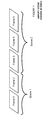
- Fig. 1 illustrates a series of video frames that contains two scenes in a video in which the scene change from the first scene to the second scene is abrupt.
- the frames on either side of the scene changes are completely different.
- a first scene of a video may be a person approaching a building from the outside, then the video changes scenes to a view of the person entering the building from the inside.
- the last frame of the first scene and the first frame of the second scene are radically different.
- Other scene changes happen gradually over a number of video frames. These gradual scene changes may include fades, wipes, dissolves, etc.
- Embodiments of the invention are directed to the former types of scene changes.
- One popular method of detecting scene changes in uncompressed video streams is to use an intensity histogram.
- the histogram difference between two consecutive video frames is computed. This difference is then compared against a threshold to decide whether a scene cut occurred between the two frames.
- a potential drawback of such an approach is how to choose the threshold. Sometimes a global threshold applied to all of the frames across a video sequence would yield better results, but other times a local threshold would be better.
- Another possible limitation with the histogram approach is that it has difficulty detecting between two images that have different structure but similar pixel values.
- Embodiments of the invention address these and other limitations of the prior art.
- Some aspects of the invention include methods for detecting scene changes in a video that may include a number of different scenes.
- One such method includes accepting at least two frames of video at a video input and computing a difference metric between two adjacent video frames. Next the method detects whether an output of the difference metric calculator contains measurements outside of a threshold level of standard deviations of a Gaussian distribution. When such outliers exist, the method indicates the video as having a scene change.
- the difference metric may include root mean squared error, for example.
- the method may also include outlier detection to verify that a pair of outliers is based on data from the same element in at least one same-sized sliding window.
- a video detector for detecting scene changes in a video that may include a number of different scenes, in which the video includes a plurality of frames each made from individual pixels.
- a video detector includes an input for accepting the video, a difference metric calculator for computing a difference metric between two adjacent video frames, and an outlier detector to detect whether an output of the difference metric calculator contains measurements outside of a threshold level of standard deviations of a Gaussian distribution. Once calculated, an identifier of the video detector indicates the video as having a scene change based on an output of the outlier detector.
- Fig. 1 illustrates a series of video frames that contains two scenes in a video in which the scene change from the first scene to the second scene is abrupt.
- Fig. 2 illustrates the behavior of the difference metric between adjacent frames, in an interval of frames with no scene cut, used by embodiments of the invention.
- Fig. 3 illustrates the behavior of the difference metric between adjacent frames, in an interval of frames with one scene cut, used by embodiments of the invention.
- Fig. 4 is flowchart illustrating an example method of detecting scene cuts in a video according to embodiments of the invention.
- Fig. 5 is an example window size used by the block matching method for the false alarm detector according to embodiments of the invention.
- Fig. 6 is a flowchart illustrating an example method of detecting false alarms for scene cuts in a video, according to embodiments of the invention.
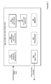
- Fig. 7 is a block diagram illustrating components of a video detector structured to identify scene cuts of a video according to embodiments of the invention.
- Embodiments of the invention use statistical modeling to detect scene changes in a video. Difference metrics are calculated between two consecutive video frames, then the data of the metric is statistically analyzed to seek outliers. If outliers exist, it is likely that the frames used to calculate the metric are from different scenes. Variations of the method are used to decrease the probability of false positive results.
- RMSE root mean squared error
- N x is the pixel x of the luma component in frame N;
- (n-1) x is the pixel x of the luma component in frame N-1;
- x ranges from 0 to (frame_luma_width * frame_luma_height)
- Fig. 2 illustrates this behavior.
- Fig. 2 is a plot of RMSE values plotted against the number of samples for a test video sequence that has no abrupt scene cuts.
- Fig. 3 illustrates a plot of RMSE values for a video test sequence that has an abrupt scene cut. It is evident in Fig. 3 that, while most samples are centered around the mean, there is one outlier having an RMSE value of approximately 40, which is approximately 8 times away from the mean. This outlying RMSE value corresponds to a scene cut at that frame, which was confirmed by manual inspection.
- Embodiments of the invention therefore, detect outliers in a difference metric, such as RMSE samples for a specified window size.
- a difference metric such as RMSE samples for a specified window size.
- One such statistical method is Huber's method, detailed in AMC Technical Brief, No. 6, April 2001, entitled “Robust Statistics: a method of coping with outliers ", which is incorporated by reference herein.
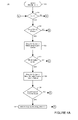
- FIGs. 4A - 4C illustrate an example method according to embodiments.
- a flow 100 begins at a first frame of a video sequence in an operation 110.
- a decision operation 114 checks to see if the current frame is at least the second frame in the video sequence. Since the first frame is not at least the second frame, the decision operation 114 initially exits in the NO direction, and the flow 100 proceeds to operation 168 ( Fig. 4C ) where the next frame in the video sequence is acquired. Because the end of the video sequence has not yet been reached, the decision operation 170 exits in the NO direction, and the flow 100 loops back to the operation 114 ( Fig. 4A ).
- the size of the sliding window may be user specified. Assuming the end of the sliding window has not been reached, the operation 116 exits in the NO direction, and the flow 100 continues at a process 160 ( Fig. 4C ), where the RMSE difference metric is computed between the frames N and N-1.
- An operation 162 then computes a block mismatch percentage between the frames N and N-1, which is described in detail with reference to Figs. 5 and 6 below.
- the flow 100 proceeds to an operation 164, which combines the RMSE and block mismatch percentage calculated in operations 160 and 162, respectively, and the sliding window size is increased by 1.
- the flow 100 then selects the next frame in the video sequence in the operation 168. If the decision operation 170 determines that the last frame in the video sequence has not been reached, then the flow 100 repeats again at the process 114.
- the flow 100 exits the decision operation 116 in the YES direction. Then outliers are determined using a statistical method such as Huber's method described above in an operation 120. If such an outlier exists, the decision operation 122 exits in the YES direction and outliers are determined in the block mismatch percentage, again using Huber's method in an operation 124.
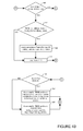
- a decision operation 140 ( Fig. 4B ) checks to see if the loop index is less than the size of the sliding window. Because for the first time through this branch the loop index is necessarily less than the sliding window size, the decision operation 140 exits in the YES direction. A decision operation 142 then verifies that both outliers in the RMSE and the block mismatch percentage outlier are pointing to the same element in the sliding window. If so, then the decision operation 142 exits in the YES direction and it is determined that the scene cut exists at frame number N-sliding_window_size - loop index). The loop index is then incremented in an operation 146, and the branch continues back at operation 140 until the loop index equals the size of the sliding window.
- the flow 100 continues to a decision operation 150. If the scene cut was detected in the operation 144, the decision operation 150 exits in the YES direction, and data for the RMSE and the bock mismatch is moved from the point of the scene cut detection in the sliding window to the beginning of the sliding window in an operation 152, and the flow 100 continues at operation 160 ( Fig. 4C ). If instead no scene cut was detected in the operation 144, then the decision operation 150 exits in the NO direction, and the sliding window statistics for both the RMSE and the block mismatch are moved from 1 ⁇ 2 of the sliding window size to the beginning of the sliding window, and again the flow 100 continues at operation 160 ( Fig. 4C ).
- P0 is the co-located block of the current block in Frame (N-1); P0:P48 are the blocks in Frame (N-1) against which the current block is matched; and Window X and Window Y are user configurable sizes of the matching window.
- frames N and N-1 are divided into a number of two-dimensional 16x16 blocks, for example, in an operation 222. Also, although not illustrated, for each block 'x' in frame N, the mean of the luma component for block x is computed as mean x.
- a mean luma component for block y is computed as mean y, and compared to mean x , in an operation 240.
- a decision operation 250 if mean x is outside the error tolerance range, such as five units of every mean y, then a block mismatch count is incremented in an operation 260. Then the block counter is incremented as well in an operation 270.
- a block mismatch percentage is calculated in an operation 280 as the (block mismatch count / total number of blocks) * 100.
- a refinement of the block matching method includes using block sizes different than 16x16 in the operation 122. Also, the mean values of the overlapping neighboring blocks could be stored so that the mean does not have to be calculated in every block.
- a scene change detector for detecting scene changes in a video that may include a number of different scenes may include elements as illustrated in Fig. 7 .
- a scene change detector 700 includes an input for accepting the video.
- a difference metric calculator 720 is used to compute a difference metric of a luma component between two adjacent video frames as described above with reference to Figs 4A-4C .
- the difference metric calculator may calculate a root mean squared error between the two adjacent video frames.
- the scene change detector 700 also includes an outlier detector 730 to detect whether an output of the difference metric calculator 720 contains measurements outside of a threshold level of standard deviations of a Gaussian distribution. An identifier 750 may then indicate the video as having a scene change based on an output of the outlier detector, and further may indicate the location of the scene change.
- the scene change detector 700 may also include an outlier detector verifier 732 structured to verify that a pair of outliers is based on data from the same element in at least one same-sized sliding window. This reduces the chance of falsely labeling a scene change when there actually is no scene change.
- the scene change detector 700 may also include a block mismatch calculator structured to compare a block of a first of the two adjacent frames to a set of blocks of a second of the two adjacent frames, and in some embodiments the block mismatch calculator is structured to operate on various sized blocks. Any of the functions illustrated in the functional block diagram of Fig. 7 may be implemented by a processor 760, and may be stored in related memory 770.
Landscapes
- Engineering & Computer Science (AREA)
- Multimedia (AREA)
- Theoretical Computer Science (AREA)
- Physics & Mathematics (AREA)
- General Physics & Mathematics (AREA)
- Signal Processing (AREA)
- Computing Systems (AREA)
- Television Signal Processing For Recording (AREA)
- Image Analysis (AREA)
- Compression Or Coding Systems Of Tv Signals (AREA)
Abstract
Description
- This disclosure is directed toward analysis of video, and, more particularly, to detecting when scene cuts occur in a video stream.
- A video sequence is made from a set of video frames having a certain temporal distance between the frames. As part of a given 'scene,' the video frames within it have a temporal coherence. Scene cuts are introduced at various points in the video sequence due to a number of factors such as video editing effects, changing camera angles, and artistic effects, etc., as well as due to scene changes themselves.
-
Fig. 1 illustrates a series of video frames that contains two scenes in a video in which the scene change from the first scene to the second scene is abrupt. In an abrupt scene change, the frames on either side of the scene changes are completely different. For example a first scene of a video may be a person approaching a building from the outside, then the video changes scenes to a view of the person entering the building from the inside. In this instance, the last frame of the first scene and the first frame of the second scene are radically different. Other scene changes happen gradually over a number of video frames. These gradual scene changes may include fades, wipes, dissolves, etc. Embodiments of the invention are directed to the former types of scene changes. - Several approaches exist for detecting scene changes, but they may be broadly classified into one of two categories - those that analyze compressed video streams and those that analyze uncompressed video streams. The latter type is also called analysis in the uncompressed pixel domain, and is the category to which the invention is directed.
- One popular method of detecting scene changes in uncompressed video streams is to use an intensity histogram. In this method the histogram difference between two consecutive video frames is computed. This difference is then compared against a threshold to decide whether a scene cut occurred between the two frames. A potential drawback of such an approach is how to choose the threshold. Sometimes a global threshold applied to all of the frames across a video sequence would yield better results, but other times a local threshold would be better. Another possible limitation with the histogram approach is that it has difficulty detecting between two images that have different structure but similar pixel values.
- Embodiments of the invention address these and other limitations of the prior art.
- Some aspects of the invention include methods for detecting scene changes in a video that may include a number of different scenes. One such method includes accepting at least two frames of video at a video input and computing a difference metric between two adjacent video frames. Next the method detects whether an output of the difference metric calculator contains measurements outside of a threshold level of standard deviations of a Gaussian distribution. When such outliers exist, the method indicates the video as having a scene change. The difference metric may include root mean squared error, for example. The method may also include outlier detection to verify that a pair of outliers is based on data from the same element in at least one same-sized sliding window.
- Other aspects of the invention include a video detector for detecting scene changes in a video that may include a number of different scenes, in which the video includes a plurality of frames each made from individual pixels. Such a video detector includes an input for accepting the video, a difference metric calculator for computing a difference metric between two adjacent video frames, and an outlier detector to detect whether an output of the difference metric calculator contains measurements outside of a threshold level of standard deviations of a Gaussian distribution. Once calculated, an identifier of the video detector indicates the video as having a scene change based on an output of the outlier detector.
-
Fig. 1 illustrates a series of video frames that contains two scenes in a video in which the scene change from the first scene to the second scene is abrupt. -
Fig. 2 illustrates the behavior of the difference metric between adjacent frames, in an interval of frames with no scene cut, used by embodiments of the invention. -
Fig. 3 illustrates the behavior of the difference metric between adjacent frames, in an interval of frames with one scene cut, used by embodiments of the invention. -
Fig. 4 is flowchart illustrating an example method of detecting scene cuts in a video according to embodiments of the invention. -
Fig. 5 is an example window size used by the block matching method for the false alarm detector according to embodiments of the invention. -
Fig. 6 is a flowchart illustrating an example method of detecting false alarms for scene cuts in a video, according to embodiments of the invention. -
Fig. 7 is a block diagram illustrating components of a video detector structured to identify scene cuts of a video according to embodiments of the invention. - Embodiments of the invention use statistical modeling to detect scene changes in a video. Difference metrics are calculated between two consecutive video frames, then the data of the metric is statistically analyzed to seek outliers. If outliers exist, it is likely that the frames used to calculate the metric are from different scenes. Variations of the method are used to decrease the probability of false positive results.
- One difference metric is root mean squared error (RMSE). In this embodiment an RMSE is calculated for the luminance component of two adjacent frames represented in YUV format, which is a format often found in streaming video that enhances luminance values over chrominance values.
- An RMSE formula is set forth below as:
- RMSE = Square Root (MSE), where

- where
- Nx is the pixel x of the luma component in frame N;
- (n-1)x is the pixel x of the luma component in frame N-1; and
- x ranges from 0 to (frame_luma_width * frame_luma_height)
- The statistical behavior exhibited by the RMSE values, over a sliding window, approximates a Gaussian distribution, with most of the values centered around the mean, and several within one standard deviation from the mean.
-
Fig. 2 illustrates this behavior.Fig. 2 is a plot of RMSE values plotted against the number of samples for a test video sequence that has no abrupt scene cuts. By using the known property that 95% of the samples of a distribution exhibiting Gaussian properties lies within two standard deviations from the mean, it may be assumed that anything that lies outside of two standard deviations from the mean of an RMSE distribution may be considered a potential outlier.Fig. 3 illustrates a plot of RMSE values for a video test sequence that has an abrupt scene cut. It is evident inFig. 3 that, while most samples are centered around the mean, there is one outlier having an RMSE value of approximately 40, which is approximately 8 times away from the mean. This outlying RMSE value corresponds to a scene cut at that frame, which was confirmed by manual inspection. - Embodiments of the invention, therefore, detect outliers in a difference metric, such as RMSE samples for a specified window size. One such statistical method is Huber's method, detailed in AMC Technical Brief, No. 6, April 2001, entitled "Robust Statistics: a method of coping with outliers", which is incorporated by reference herein.
- Sometimes, however, effects such as camera pan or zoom, appearance of text captions, or a few dropped frames between two consecutive frames of a video sequence can also produce a spike in RMSE values. Without error detection, these RMSE spikes would be categorized as outliers, and therefore falsely as scene cuts. To minimize such a possibility of false attributions, embodiments of the invention include a block matching method described below.
-
Figs. 4A - 4C illustrate an example method according to embodiments. Aflow 100 begins at a first frame of a video sequence in anoperation 110. Adecision operation 114 checks to see if the current frame is at least the second frame in the video sequence. Since the first frame is not at least the second frame, thedecision operation 114 initially exits in the NO direction, and theflow 100 proceeds to operation 168 (Fig. 4C ) where the next frame in the video sequence is acquired. Because the end of the video sequence has not yet been reached, thedecision operation 170 exits in the NO direction, and theflow 100 loops back to the operation 114 (Fig. 4A ). - The flow then proceeds to an
operation 116, where a decision operation determines if the end of the sliding window has been reached, described below. The size of the sliding window may be user specified. Assuming the end of the sliding window has not been reached, theoperation 116 exits in the NO direction, and theflow 100 continues at a process 160 (Fig. 4C ), where the RMSE difference metric is computed between the frames N and N-1. - An
operation 162 then computes a block mismatch percentage between the frames N and N-1, which is described in detail with reference toFigs. 5 and6 below. - Next, the
flow 100 proceeds to anoperation 164, which combines the RMSE and block mismatch percentage calculated inoperations - The
flow 100 then selects the next frame in the video sequence in theoperation 168. If thedecision operation 170 determines that the last frame in the video sequence has not been reached, then theflow 100 repeats again at theprocess 114. - With reference back to operation 116 (
Fig. 4A ), if instead the end of the sliding window has been reached, then theflow 100 exits thedecision operation 116 in the YES direction. Then outliers are determined using a statistical method such as Huber's method described above in an operation 120. If such an outlier exists, thedecision operation 122 exits in the YES direction and outliers are determined in the block mismatch percentage, again using Huber's method in anoperation 124. - If such outliers exist in the block mismatch percentage, then the
flow 100 continues to anoperation 130, which begins a sequence to check for a false positive scene detection. - To check for such a false positive, first a decision operation 140 (
Fig. 4B ) checks to see if the loop index is less than the size of the sliding window. Because for the first time through this branch the loop index is necessarily less than the sliding window size, thedecision operation 140 exits in the YES direction. Adecision operation 142 then verifies that both outliers in the RMSE and the block mismatch percentage outlier are pointing to the same element in the sliding window. If so, then thedecision operation 142 exits in the YES direction and it is determined that the scene cut exists at frame number N-sliding_window_size - loop index). The loop index is then incremented in anoperation 146, and the branch continues back atoperation 140 until the loop index equals the size of the sliding window. - When the loop index equals the size of the sliding window, the
flow 100 continues to adecision operation 150. If the scene cut was detected in theoperation 144, thedecision operation 150 exits in the YES direction, and data for the RMSE and the bock mismatch is moved from the point of the scene cut detection in the sliding window to the beginning of the sliding window in anoperation 152, and theflow 100 continues at operation 160 (Fig. 4C ). If instead no scene cut was detected in theoperation 144, then thedecision operation 150 exits in the NO direction, and the sliding window statistics for both the RMSE and the block mismatch are moved from ½ of the sliding window size to the beginning of the sliding window, and again theflow 100 continues at operation 160 (Fig. 4C ). - The block matching method referred to in operation 162 (
Fig. 4C ) is described below with reference toFigs. 5 and6 . In these figures: P0 is the co-located block of the current block in Frame (N-1); P0:P48 are the blocks in Frame (N-1) against which the current block is matched; and Window X and Window Y are user configurable sizes of the matching window. - An outline of the block match method is now described with reference to a
flow 200 inFig. 6 . After aninitialization operation 220, frames N and N-1 are divided into a number of two-dimensional 16x16 blocks, for example, in anoperation 222. Also, although not illustrated, for each block 'x' in frame N, the mean of the luma component for block x is computed as mean x. - Then, so long as the block counter has not reached the last block in
decision operation 230, for each block 'y' in the Window X * Window Y in frame (N-1), a mean luma component for block y is computed as mean y, and compared to mean x, in anoperation 240. In adecision operation 250, if mean x is outside the error tolerance range, such as five units of every mean y, then a block mismatch count is incremented in anoperation 260. Then the block counter is incremented as well in anoperation 270. - Finally, after each block y has been so evaluated for every block x, a block mismatch percentage is calculated in an
operation 280 as the (block mismatch count / total number of blocks) * 100. - A refinement of the block matching method includes using block sizes different than 16x16 in the
operation 122. Also, the mean values of the overlapping neighboring blocks could be stored so that the mean does not have to be calculated in every block. - A scene change detector for detecting scene changes in a video that may include a number of different scenes may include elements as illustrated in
Fig. 7 . InFig. 7 , ascene change detector 700 includes an input for accepting the video. A differencemetric calculator 720 is used to compute a difference metric of a luma component between two adjacent video frames as described above with reference toFigs 4A-4C . In some embodiments the difference metric calculator may calculate a root mean squared error between the two adjacent video frames. - The
scene change detector 700 also includes anoutlier detector 730 to detect whether an output of the differencemetric calculator 720 contains measurements outside of a threshold level of standard deviations of a Gaussian distribution. Anidentifier 750 may then indicate the video as having a scene change based on an output of the outlier detector, and further may indicate the location of the scene change. - The
scene change detector 700 may also include anoutlier detector verifier 732 structured to verify that a pair of outliers is based on data from the same element in at least one same-sized sliding window. This reduces the chance of falsely labeling a scene change when there actually is no scene change. - The
scene change detector 700 may also include a block mismatch calculator structured to compare a block of a first of the two adjacent frames to a set of blocks of a second of the two adjacent frames, and in some embodiments the block mismatch calculator is structured to operate on various sized blocks. Any of the functions illustrated in the functional block diagram ofFig. 7 may be implemented by aprocessor 760, and may be stored inrelated memory 770.
Claims (12)
- A video detector for detecting scene changes in a video that may include a number of different scenes, the video including a plurality of frames each made from individual pixels, the detector comprising:an input for accepting the video;a difference metric calculator for computing a difference metric between two adjacent video frames;an outlier detector to detect whether an output of the difference metric calculator contains measurements outside of a threshold level of standard deviations of a Gaussian distribution; andan identifier structured to indicate the video as having a scene change based on an output of the outlier detector.
- The video detector for detecting scene changes according to claim 1 in which the difference metric calculator calculates a root mean squared error between the two adjacent video frames.
- The video detector for detecting scene changes according to claim 2 in which the two adjacent video frames are represented in YUV format and in which the difference metric calculator calculates a root mean squared error for a luminance component of the two adjacent video frames.
- The video detector for detecting scene changes according to claim 3, further comprising:an outlier detector verifier structured to verify that a pair of outliers is based on data from the same element in at least one same-sized sliding window.
- The video detector for detecting scene changes according to claim 1, further comprising:a block mismatch calculator structured to compare a block of a first of the two adjacent frames to a set of blocks of a second of the two adjacent frames.
- The video detector for detecting scene changes according to claim 6, in which the set of blocks of the second of the two adjacent frames to which the block of the first of the two adjacent frames is compared is configurable.
- A method for detecting scene changes in an video that may include a number of different scenes, the method comprising:accepting at least two frames of video at a video input;computing a difference metric between two adjacent video frames;detecting whether an output of the difference metric calculator contains measurements outside of a threshold level of standard deviations of a Gaussian distribution; andindicating the video as having a scene change based on an output of the outlier detector.
- The method for detecting scene changes according to claim 7, in which computing a difference metric between two adjacent video frames comprises calculating a root mean squared error between the two adjacent video frames.
- The method for detecting scene changes according to claim 7 in which the two adjacent video frames are represented in YUV format and in which computing a difference metric between two adjacent video frames comprises calculating a root mean squared error for a luminance component of the two adjacent video frames.
- The method for detecting scene changes according to claim 7, further comprising:verifying that a pair of outliers is based on data from the same element in at least one same-sized sliding window.
- The method for detecting scene changes according to claim 7, further comprising:comparing a block of a first of the two adjacent frames to a set of blocks of a second of the two adjacent frames.
- The method for detecting scene changes according to claim 11, in which the set of blocks of the second of the two adjacent frames to which the block of the first of the two adjacent frames is compared is configurable.
Applications Claiming Priority (1)
| Application Number | Priority Date | Filing Date | Title |
|---|---|---|---|
| IN3101MU2012 | 2012-10-25 |
Publications (2)
| Publication Number | Publication Date |
|---|---|
| EP2725523A2 true EP2725523A2 (en) | 2014-04-30 |
| EP2725523A3 EP2725523A3 (en) | 2016-11-02 |
Family
ID=49518672
Family Applications (1)
| Application Number | Title | Priority Date | Filing Date |
|---|---|---|---|
| EP13190209.0A Withdrawn EP2725523A3 (en) | 2012-10-25 | 2013-10-25 | Heuristic method for scene cut detection in digital baseband video |
Country Status (4)
| Country | Link |
|---|---|
| US (1) | US9183445B2 (en) |
| EP (1) | EP2725523A3 (en) |
| JP (1) | JP2014087070A (en) |
| CN (1) | CN103780801A (en) |
Families Citing this family (6)
| Publication number | Priority date | Publication date | Assignee | Title |
|---|---|---|---|---|
| CN105227999B (en) * | 2015-09-29 | 2018-12-14 | 北京奇艺世纪科技有限公司 | A kind of method and apparatus that video is cut |
| US12079274B2 (en) * | 2018-10-16 | 2024-09-03 | NBCUniversal Studios LLC | Systems and methods for identifying scene changes in video files |
| CN110248182B (en) * | 2019-05-31 | 2021-01-15 | 成都东方盛行电子有限责任公司 | Scene segment shot detection method |
| CN112365567B (en) * | 2020-10-14 | 2021-06-22 | 北京完美赤金科技有限公司 | Scene switching method, device and equipment |
| CN112966669A (en) * | 2021-04-06 | 2021-06-15 | 海南电网有限责任公司儋州供电局 | Identification method suitable for video stream detection |
| CN115389624B (en) * | 2022-10-27 | 2023-02-10 | 智能网联汽车(山东)协同创新研究院有限公司 | Sound wave test system for processing |
Family Cites Families (12)
| Publication number | Priority date | Publication date | Assignee | Title |
|---|---|---|---|---|
| JP2839132B2 (en) * | 1993-12-17 | 1998-12-16 | 日本電信電話株式会社 | Image cut point detection method and apparatus |
| US5835163A (en) * | 1995-12-21 | 1998-11-10 | Siemens Corporate Research, Inc. | Apparatus for detecting a cut in a video |
| US5847776A (en) * | 1996-06-24 | 1998-12-08 | Vdonet Corporation Ltd. | Method for entropy constrained motion estimation and coding of motion vectors with increased search range |
| GB2319684B (en) * | 1996-11-26 | 2000-09-06 | Sony Uk Ltd | Scene change detection |
| US6118817A (en) * | 1997-03-14 | 2000-09-12 | Microsoft Corporation | Digital video signal encoder and encoding method having adjustable quantization |
| US5990980A (en) * | 1997-12-23 | 1999-11-23 | Sarnoff Corporation | Detection of transitions in video sequences |
| JP3524007B2 (en) * | 1998-10-14 | 2004-04-26 | シャープ株式会社 | Moving image scene changing unit detecting apparatus and method, medium storing moving image scene changing unit detection control program, and moving image processing apparatus |
| US6876705B2 (en) * | 2001-03-05 | 2005-04-05 | Intervideo, Inc. | Systems and methods for decoding of partially corrupted reversible variable length code (RVLC) intra-coded macroblocks and partial block decoding of corrupted macroblocks in a video decoder |
| US20060109902A1 (en) * | 2004-11-19 | 2006-05-25 | Nokia Corporation | Compressed domain temporal segmentation of video sequences |
| JP2006260237A (en) * | 2005-03-17 | 2006-09-28 | Tama Tlo Kk | Specific scene extraction method by comprehensive determination system using mahalanobis distance, and device thereof |
| DE102005017422A1 (en) * | 2005-04-15 | 2006-10-19 | Robert Bosch Gmbh | Driver assistance system with device for detecting stationary objects |
| US8472725B2 (en) * | 2010-06-02 | 2013-06-25 | Cisco Technology, Inc. | Scene change detection and handling for preprocessing video with overlapped 3D transforms |
-
2013
- 2013-10-24 CN CN201310631179.6A patent/CN103780801A/en active Pending
- 2013-10-25 US US14/063,824 patent/US9183445B2/en not_active Expired - Fee Related
- 2013-10-25 JP JP2013222446A patent/JP2014087070A/en not_active Ceased
- 2013-10-25 EP EP13190209.0A patent/EP2725523A3/en not_active Withdrawn
Non-Patent Citations (1)
| Title |
|---|
| None |
Also Published As
| Publication number | Publication date |
|---|---|
| JP2014087070A (en) | 2014-05-12 |
| EP2725523A3 (en) | 2016-11-02 |
| US20140119666A1 (en) | 2014-05-01 |
| CN103780801A (en) | 2014-05-07 |
| US9183445B2 (en) | 2015-11-10 |
Similar Documents
| Publication | Publication Date | Title |
|---|---|---|
| US9183445B2 (en) | Heuristic method for scene cut detection in digital baseband video | |
| CN109076198B (en) | Video-based object tracking occlusion detection system, method and equipment | |
| US12002195B2 (en) | Computer vision-based anomaly detection method, device and electronic apparatus | |
| CN103458266B (en) | Heuristic method for drop frame detection in digital baseband video | |
| KR100591470B1 (en) | Transform detection of video sequence | |
| JP5908174B2 (en) | Image processing apparatus and image processing method | |
| US9479681B2 (en) | System and method for shot change detection in a video sequence | |
| CN111160187B (en) | Method, device and system for detecting left-behind object | |
| US8947600B2 (en) | Methods, systems, and computer-readable media for detecting scene changes in a video | |
| CN104135597B (en) | A kind of video jitter automatic testing method | |
| US20100310122A1 (en) | Method and Device for Detecting Stationary Targets | |
| US9384400B2 (en) | Method and apparatus for identifying salient events by analyzing salient video segments identified by sensor information | |
| JPWO2018061976A1 (en) | Image processing device | |
| US9232118B1 (en) | Methods and systems for detecting video artifacts | |
| US9818178B1 (en) | Method and system for detection of ghosting artifact in a video | |
| CN104717402A (en) | Space-time domain joint noise estimation system | |
| US20170214935A1 (en) | Method and device for processing a video sequence | |
| CN107590431B (en) | Quantity counting method and device based on image recognition | |
| KR101452541B1 (en) | Video signal analysis | |
| US9659220B2 (en) | Method and apparatus for updating scene model and video surveillance | |
| US9877022B2 (en) | Video sequence processing of pixel-to-pixel dissimilarity values | |
| EP2667354B1 (en) | Method and apparatus for analyzing stereoscopic or multi-view images | |
| CN109598276A (en) | Image processing apparatus and method and monitoring system | |
| US20180013932A1 (en) | Detecting shot changes in a video | |
| US8743968B2 (en) | Method and apparatus for analysing image data to quantify prior blockbased processing of the data |
Legal Events
| Date | Code | Title | Description |
|---|---|---|---|
| PUAI | Public reference made under article 153(3) epc to a published international application that has entered the european phase |
Free format text: ORIGINAL CODE: 0009012 |
|
| 17P | Request for examination filed |
Effective date: 20131025 |
|
| AK | Designated contracting states |
Kind code of ref document: A2 Designated state(s): AL AT BE BG CH CY CZ DE DK EE ES FI FR GB GR HR HU IE IS IT LI LT LU LV MC MK MT NL NO PL PT RO RS SE SI SK SM TR |
|
| AX | Request for extension of the european patent |
Extension state: BA ME |
|
| RAP1 | Party data changed (applicant data changed or rights of an application transferred) |
Owner name: TEKTRONIX, INC. |
|
| PUAL | Search report despatched |
Free format text: ORIGINAL CODE: 0009013 |
|
| AK | Designated contracting states |
Kind code of ref document: A3 Designated state(s): AL AT BE BG CH CY CZ DE DK EE ES FI FR GB GR HR HU IE IS IT LI LT LU LV MC MK MT NL NO PL PT RO RS SE SI SK SM TR |
|
| AX | Request for extension of the european patent |
Extension state: BA ME |
|
| RIC1 | Information provided on ipc code assigned before grant |
Ipc: H04N 5/14 20060101ALI20160927BHEP Ipc: G06K 9/00 20060101AFI20160927BHEP |
|
| 17P | Request for examination filed |
Effective date: 20170502 |
|
| RBV | Designated contracting states (corrected) |
Designated state(s): AL AT BE BG CH CY CZ DE DK EE ES FI FR GB GR HR HU IE IS IT LI LT LU LV MC MK MT NL NO PL PT RO RS SE SI SK SM TR |
|
| 17Q | First examination report despatched |
Effective date: 20180423 |
|
| STAA | Information on the status of an ep patent application or granted ep patent |
Free format text: STATUS: THE APPLICATION IS DEEMED TO BE WITHDRAWN |
|
| 18D | Application deemed to be withdrawn |
Effective date: 20190501 |