EP2725426A2 - Image forming apparatus and control method thereof - Google Patents
Image forming apparatus and control method thereof Download PDFInfo
- Publication number
- EP2725426A2 EP2725426A2 EP13189767.0A EP13189767A EP2725426A2 EP 2725426 A2 EP2725426 A2 EP 2725426A2 EP 13189767 A EP13189767 A EP 13189767A EP 2725426 A2 EP2725426 A2 EP 2725426A2
- Authority
- EP
- European Patent Office
- Prior art keywords
- transfer belt
- transfer
- photoconductors
- driving motor
- rollers
- Prior art date
- Legal status (The legal status is an assumption and is not a legal conclusion. Google has not performed a legal analysis and makes no representation as to the accuracy of the status listed.)
- Granted
Links
Images






Classifications
-
- G—PHYSICS
- G03—PHOTOGRAPHY; CINEMATOGRAPHY; ANALOGOUS TECHNIQUES USING WAVES OTHER THAN OPTICAL WAVES; ELECTROGRAPHY; HOLOGRAPHY
- G03G—ELECTROGRAPHY; ELECTROPHOTOGRAPHY; MAGNETOGRAPHY
- G03G15/00—Apparatus for electrographic processes using a charge pattern
- G03G15/14—Apparatus for electrographic processes using a charge pattern for transferring a pattern to a second base
- G03G15/16—Apparatus for electrographic processes using a charge pattern for transferring a pattern to a second base of a toner pattern, e.g. a powder pattern, e.g. magnetic transfer
- G03G15/1665—Apparatus for electrographic processes using a charge pattern for transferring a pattern to a second base of a toner pattern, e.g. a powder pattern, e.g. magnetic transfer by introducing the second base in the nip formed by the recording member and at least one transfer member, e.g. in combination with bias or heat
-
- G—PHYSICS
- G03—PHOTOGRAPHY; CINEMATOGRAPHY; ANALOGOUS TECHNIQUES USING WAVES OTHER THAN OPTICAL WAVES; ELECTROGRAPHY; HOLOGRAPHY
- G03G—ELECTROGRAPHY; ELECTROPHOTOGRAPHY; MAGNETOGRAPHY
- G03G15/00—Apparatus for electrographic processes using a charge pattern
- G03G15/01—Apparatus for electrographic processes using a charge pattern for producing multicoloured copies
-
- G—PHYSICS
- G03—PHOTOGRAPHY; CINEMATOGRAPHY; ANALOGOUS TECHNIQUES USING WAVES OTHER THAN OPTICAL WAVES; ELECTROGRAPHY; HOLOGRAPHY
- G03G—ELECTROGRAPHY; ELECTROPHOTOGRAPHY; MAGNETOGRAPHY
- G03G15/00—Apparatus for electrographic processes using a charge pattern
- G03G15/01—Apparatus for electrographic processes using a charge pattern for producing multicoloured copies
- G03G15/0105—Details of unit
- G03G15/0131—Details of unit for transferring a pattern to a second base
- G03G15/0136—Details of unit for transferring a pattern to a second base transfer member separable from recording member or vice versa, mode switching
-
- G—PHYSICS
- G03—PHOTOGRAPHY; CINEMATOGRAPHY; ANALOGOUS TECHNIQUES USING WAVES OTHER THAN OPTICAL WAVES; ELECTROGRAPHY; HOLOGRAPHY
- G03G—ELECTROGRAPHY; ELECTROPHOTOGRAPHY; MAGNETOGRAPHY
- G03G15/00—Apparatus for electrographic processes using a charge pattern
- G03G15/14—Apparatus for electrographic processes using a charge pattern for transferring a pattern to a second base
-
- G—PHYSICS
- G03—PHOTOGRAPHY; CINEMATOGRAPHY; ANALOGOUS TECHNIQUES USING WAVES OTHER THAN OPTICAL WAVES; ELECTROGRAPHY; HOLOGRAPHY
- G03G—ELECTROGRAPHY; ELECTROPHOTOGRAPHY; MAGNETOGRAPHY
- G03G15/00—Apparatus for electrographic processes using a charge pattern
- G03G15/14—Apparatus for electrographic processes using a charge pattern for transferring a pattern to a second base
- G03G15/16—Apparatus for electrographic processes using a charge pattern for transferring a pattern to a second base of a toner pattern, e.g. a powder pattern, e.g. magnetic transfer
- G03G15/1605—Apparatus for electrographic processes using a charge pattern for transferring a pattern to a second base of a toner pattern, e.g. a powder pattern, e.g. magnetic transfer using at least one intermediate support
- G03G15/1615—Apparatus for electrographic processes using a charge pattern for transferring a pattern to a second base of a toner pattern, e.g. a powder pattern, e.g. magnetic transfer using at least one intermediate support relating to the driving mechanism for the intermediate support, e.g. gears, couplings, belt tensioning
Definitions
- Embodiments relate to an image forming apparatus having a transfer device transferring developing agents from a plurality of developing units to paper, and a control method thereof.
- An electrophotographic image forming apparatus for example, a laser printer, a digital copier, or a multi-function apparatus, refers to an apparatus which radiates light to photoconductors charged with a designated electric potential to form electrostatic latent images on the outer surfaces of the photoconductors, supplies toners, i.e., developing agents, to the electrostatic latent images to form visible images, and transfers and fixes the visible images to a printing medium to print the images.
- a color image forming apparatus includes a plurality of photoconductors converting electrostatic latent images into visible images through developing agents, a transfer belt to which the visible images formed by the plurality of photoconductors are transferred, a transfer belt driving motor to rotate the transfer belt, and a plurality of transfer rollers pressing the transfer belt toward the photoconductors and causing the transfer belt to come into contact with the photoconductors so as to transfer the visible images on the photoconductors to the transfer belt.
- the transfer belt in the rotating state contacts the photoconductors when one or more transfer rollers press the transfer belt so as to achieve contact between the transfer belt and the photoconductors, the transfer belt, the transfer rollers, and the photoconductors may be damaged, and a printed matter may be contaminated due to triboelectrification caused by contact between the transfer belt in the rotating state and the photoconductors.
- an image forming apparatus and a control method thereof in which a transfer roller presses a transfer belt after stoppage of the transfer belt if the transfer roller presses the transfer belt to come into contact with a photoconductor, and thus contact between the transfer belt in the rotating state and the photoconductor may be prevented.
- a control method of an image forming apparatus which has a plurality of transfer rollers arranged in parallel with a plurality of photoconductors such that a transfer belt is interposed between the plurality of transfer rollers and the plurality of photoconductors and pressing the transfer belt to come into contact with the plurality of photoconductors, includes rotating the transfer belt under the condition that the plurality of transfer rollers does not press the transfer belt toward the plurality of photoconductors, interrupting power transmitted to the transfer belt to cause the plurality of transfer rollers to press the transfer belt, standing by until rotation of the transfer belt is stopped, after interruption of the power, and controlling the plurality of transfer rollers so as to press the transfer belt toward the plurality of photoconductors, when rotation of the transfer belt is stopped.
- the standing by may be carried out for a predetermined time until rotation of the transfer belt is stopped.
- the predetermined time may be time for which the transfer belt is rotated due to rotational inertia after interruption of the power transmitted to the transfer belt.
- the pressing state of the plurality of transfer rollers may be released so that all of the plurality of transfer rollers does not contact the plurality of photoconductors, and in a color mode, transfer rollers participating in formation of a color image among the plurality of transfer rollers may press the transfer belt so as to contact corresponding photoconductors.
- a control method of an image forming apparatus which has a plurality of transfer rollers arranged in parallel with a plurality of photoconductors such that a transfer belt is interposed between the plurality of transfer rollers and the plurality of photoconductors and pressing the transfer belt to come into contact with the plurality of photoconductors, includes rotating the transfer belt under the condition that the plurality of transfer rollers presses the transfer belt toward the plurality of photoconductors, interrupting power transmitted to the transfer belt to release the pressed state of the transfer belt by the plurality of transfer rollers, standing by until rotation of the transfer belt is stopped, after interruption of the power, and releasing the pressed state of the transfer belt by the plurality of transfer rollers, when rotation of the transfer belt is stopped.
- the standing by may be carried out for a predetermined time until rotation of the transfer belt is stopped.
- the predetermined time may be time taken to stop rotation of the transfer belt due to rotational inertia after interruption of the power transmitted to the transfer belt.
- the pressing state of the plurality of transfer rollers may be released so that all of the plurality of transfer rollers does not contact the plurality of photoconductors, and in a color mode, transfer rollers participating in formation of a color image among the plurality of transfer rollers may press the transfer belt so as to contact corresponding photoconductors.
- a control method of an image forming apparatus which has a plurality of transfer rollers arranged in parallel with a plurality of photoconductors such that a transfer belt is interposed between the plurality of transfer rollers and the plurality of photoconductors and pressing the transfer belt to come into contact with the plurality of photoconductors, includes rotating the transfer belt under the condition that at least one of the plurality of transfer rollers presses the transfer belt toward at least one of the plurality of photoconductors, interrupting power transmitted to the transfer belt to cause at least another of the plurality of transfer rollers to press the transfer belt toward at least another of the plurality of photoconductors, standing by until rotation of the transfer belt is stopped, after interruption of the power, and controlling the at least another of the plurality of transfer rollers so as to press the transfer belt toward the at least another of the plurality of photoconductors, when until rotation of the transfer belt is stopped.
- the standing by may be carried out for a predetermined time until rotation of the transfer belt is stopped.
- the predetermined time may be time taken to stop rotation of the transfer belt due to rotational inertia after interruption of the power transmitted to the transfer belt.
- the pressing state of the plurality of transfer rollers may be released so that all of the plurality of transfer rollers does not contact the plurality of photoconductors, in a mono mode, only a transfer roller participating in formation of a mono image among the plurality of transfer rollers may press the transfer belt so as to contact a corresponding photoconductor, and in a color mode, transfer rollers participating in formation of a color image among the plurality of transfer rollers may press the transfer belt so as to contact corresponding photoconductors.
- Mode switching may be carried out in the order of the ready mode, the mono mode, and the color mode.
- an image forming apparatus includes a plurality of photoconductors, a transfer belt, a plurality of transfer rollers arranged in parallel with the plurality of photoconductors such that the transfer belt is interposed between the plurality of transfer rollers and the plurality of photoconductors and pressing the transfer belt to come into contact with the plurality of photoconductors, and a controller rotating the transfer belt under the condition that at least one of the plurality of transfer rollers presses the transfer belt toward at least one of the plurality of photoconductors, interrupting power transmitted to the transfer belt to cause at least another of the plurality of transfer rollers to press the transfer belt toward at least another of the plurality of photoconductors, standing by until rotation of the transfer belt is stopped, after interruption of the power, and controlling the at least another of the plurality of transfer rollers so as to press the transfer belt toward the at least another of the plurality of photoconductors.
- the controller may stand by for a predetermined time until rotation of the transfer belt is stopped.
- the predetermined time may be time taken to stop rotation of the transfer belt due to rotational inertia after interruption of the power transmitted to the transfer belt.
- the pressing state of the plurality of transfer rollers may be released so that all of the plurality of transfer rollers does not contact the plurality of photoconductors, in a mono mode, only a transfer roller participating in formation of a mono image among the plurality of transfer rollers may press the transfer belt so as to contact a corresponding photoconductor, and in a color mode, transfer rollers participating in formation of a color image among the plurality of transfer rollers may press the transfer belt so as to contact corresponding photoconductors.
- Mode switching may be carried out in the order of the ready mode, the mono mode, and the color mode.
- a control method of an image forming apparatus which has a plurality of transfer rollers arranged in parallel with a plurality of photoconductors such that a transfer belt is interposed between the plurality of transfer rollers and the plurality of photoconductors and pressing the transfer belt to come into contact with the plurality of photoconductors, includes forcibly releasing the contact state between the transfer belt and the plurality of photoconductors by pressing the transfer belt using the plurality of transfer rollers, before first warm-up after being powered-on of the image forming apparatus is performed, and performing the first warm-up, when the contact state between the transfer belt and the plurality of photoconductors is released.
- an image forming apparatus includes a plurality of photoconductors, a transfer belt, a plurality of transfer rollers arranged in parallel with the plurality of photoconductors such that the transfer belt is interposed between the plurality of transfer rollers and the plurality of photoconductors and pressing the transfer belt to come into contact with the plurality of photoconductors, and a controller forcibly releasing the contact state between the transfer belt and the plurality of photoconductors by pressing the transfer belt through the plurality of transfer rollers, before first warm-up after being powered on of the image forming apparatus is performed.
- the controller may perform the first warm-up, when the contact state between the transfer belt and the plurality of photoconductors is released.
- a control method of an image forming apparatus which has a plurality of transfer rollers arranged in parallel with a plurality of photoconductors such that a transfer belt is interposed between the plurality of transfer rollers and the plurality of photoconductors and pressing the transfer belt to come into contact with the plurality of photoconductors, includes rotating the transfer belt under the condition that the plurality of transfer rollers does not press the transfer belt toward the plurality of photoconductors, interrupting power transmitted to the transfer belt to cause the plurality of transfer rollers to press the transfer belt, reducing the rotational speed of the transfer belt due to rotational inertia by controlling a transfer belt braking part, standing by until rotation of the transfer belt is stopped, and controlling the plurality of transfer rollers so as to press the transfer belt toward the plurality of photoconductors or to release the pressed state of the transfer belt by the plurality of transfer rollers, when rotation of the transfer belt is stopped.
- the transfer belt braking part may serve to reduce the rotational speed of a transfer belt driving motor to rotate the transfer belt.
- the transfer belt braking part may serve to reduce the rotational speed of a driving roller to rotate the transfer belt.
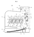
- FIG. 1 is a sectional view of an image forming apparatus in accordance with an embodiment.
- an image forming apparatus 100 in accordance with an embodiment includes a main body 10 forming the external appearance of the image forming apparatus 100, a printing medium storage unit 20 in which printing media are stored, a plurality of developing units (developers) 30C, 30M, 30Y, and 30K developing electrostatic latent images into visible images according to color through developing agents (for example, toners), an exposure unit 40 radiating light to photoconductors 31 of the charged developing units 30C, 30M, 30Y, and 30K to form the electrostatic latent images, a transfer device including a first transfer unit 50 receiving a printing medium from the printing medium storage unit 20 and a second transfer unit 60 transferring the visible images formed on the photoconductors to the printing medium, and a fixing unit 70 fixing the developing agents, transferred to the printing medium, to the printing medium.
- developing units developer
- the main body 10 is provided with a load part 10a, on which printing media having completed image formation loaded.
- the load part 10a is formed on the upper portion of the main body 10.
- An exit hole 10b through which the printing media having completed image formation exits the main body 10 is provided at one side of the load part 10a.
- An opening 10c to repair and replace parts within the main body 10 or to replace consumables within the main body 10 is provided at one side of the main body 10, and a side cover 11 to open and close the opening 10c is installed.
- the side cover 11 is configured such that the lower end of the side cover 11 is rotatably installed on the main body 10, and is rotated about the lower end of the side cover 11, thus opening and closing the opening 10c.
- the printing medium storage unit 20 includes a printing medium cassette 21 movably installed on the main body 10, a knock-up plate 22 arranged within the printing medium cassette 21 such that the printing media are loaded on the knock-up plate 22, and an elastic member 23 elastically supporting the knock-up plate 22.
- Each of the developing units 30C, 30M, 30Y, and 30K includes the photoconductor 31 provided with the charged surface on which an electrostatic latent image is formed by the exposure unit 40, a developing roller 32 supplying the developing agent to the photoconductor 31, and a charging unit 33 charging the surface of the photoconductor 31.
- four developing units 30C, 30M, 30Y, and 30K each of which stores one of cyan (C), magenta (M), yellow (Y), and black (K) developing agents to form visible images of cyan (C), magenta (M), yellow (Y), and black (K) are provided.
- the four developing units 30C, 30M, 30Y, and 30K are arranged in parallel under the transfer device.
- the exposure unit 40 radiates light containing image information to the photoconductors 31 of the developing units 30C, 30M, 30Y, and 30K, and thus forms electrostatic latent images on the surfaces of the photoconductors 31.
- the transfer device includes a first transfer unit 50 to which the visible images formed by the developing agents from the developing units 30C, 30M, 30Y, and 30K are transferred, and a second transfer unit 60 transferring the visible images on the first transfer unit 50 to a printing medium.
- the fixing unit 70 includes a heating roller 71 generating heat, and a pressure roller 72 provided with an outer circumferential surface formed of an elastically deformable material and pressing a printing medium to the outer circumferential surface of the heating roller 71.
- a pick-up unit 80 arranged on the printing medium storage unit 20 to pick up the printing media loaded on the knock-up plate 22 sheet by sheet, feed rollers 12 guiding the printing media picked up by the pick-up unit 80 upwardly, and an exit unit 90 located above the fixing unit 70 and arranged adjacent to the exit holt 10b to discharge the printing medium having passed through the fixing unit 70 to the outside of the main body 10 through the exit hole 10b are arranged within the main body 10.
- the pick-up unit 80 includes a pick-up roller 81 to pick up the printing medium on the knock-up plate 22 sheet by sheet, and the exit unit 90 includes a pair or exit rollers 91 arranged at the inside of the exit hole 10b.
- the first transfer unit 50 is arranged within the main body 10, and includes a transfer belt 51 to which the developing agents developed into the visible images on the photoconductors 31 of the developing units 30C, 30M, 30Y, and 30K are transferred so as to overlap one another.
- the first transfer unit further includes driving roller 52 and a driven roller 53 arranged at both sides of the inside of the transfer belt 51 to rotate the transfer belt 51.
- the first transfer unit 50 further includes a plurality of transfer rollers 54 arranged opposite to the photoconductors 31 of the developing units 30C, 30M, 30Y, and 30K.
- the transfer belt 51 is interposed between the transfer rollers 54 and the photoconductors 31 and transfers visible images formed on the photoconductors 31 to the transfer belt 51.
- the transfer unit 50 further includes a transfer belt frame (not shown) on which both ends of the transfer rollers 54, the driving roller 52 and the driven roller 53 are rotatably installed.
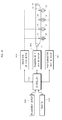
- FIG. 2 is a view illustrating a control system of an image forming apparatus in accordance with an embodiment.
- a controller 202 controlling the overall operation of the image forming apparatus 100 is electrically connected to a photoconductor driving motor 204, a transfer belt driving motor 206, and an engagement driving motor 208 so as to be communicable with the photoconductor driving motor 204, the transfer belt driving motor 206, and the engagement driving motor 208.
- the controller 202 participates in rotation and stoppage of the photoconductors 31 through control of the photoconductor driving motor 204. Further, the controller 202 participates in rotation and stoppage of the driving roller 52 and the transfer belt 51 through control of the transfer belt driving motor 206.
- the controller 202 participates in engagement and disengagement of the transfer rollers 54 through control of the engagement driving motor 208.
- engagement refers to a state in which the transfer roller 54 presses the transfer belt 51 and thus the transfer belt 51 contacts the photoconductor 31
- disengagement refers to a state in which pressing of the transfer belt 51 by the transfer roller 54 is released and thus contact between the transfer belt 51 and the photoconductor 31 is released (with reference to FIG. 3 ).
- All the four transfer rollers 54 and all the four photoconductors 31 may be engaged with or disengaged from each other, or some of the four transfer rollers 54 and some of the four photoconductors 31 may be engaged with or disengaged from each other.
- the controller 202 is electrically connected to an engagement sensor 210 and an encoder 212 so as to communicate with the engagement sensor 210 and the encoder 212.
- the engagement sensor 210 serves to detect the engagement states and disengagement states among the transfer rollers 54, the transfer belt 51 and photoconductors 31, and provides the detected state information to the controller 202.
- the encoder 212 is an encoder of the transfer belt driving motor 206. The encoder 212 detects the rotating state of the transfer belt driving motor 206, and provides the rotating state information to the controller 202.
- FIGS. 3(A) to 3(C) are views illustrating operating modes regarding the transfer device and the photoconductors of the image forming apparatus shown in FIG. 1 .
- FIG. 3(A) illustrates a ready mode prior to image formation.
- the ready mode all the transfer rollers 54, the transfer belt 51, and all the opposite photoconductors 31 are disengaged from one another.
- opposite refers to that the four transfer rollers 54 and the four photoconductors 31 corresponding to each other.
- image formation is not carried out, and thus, the disengagement state among all of the transfer rollers 54 and all of the photoconductors 31 is maintained.
- FIG. 3(B) illustrates a mono mode in which a monochromatic image is formed using a black (BK) developing agent. Since the monochromatic image is formed using only the black (BK) developing agent, the transfer roller 54, the transfer belt 51, and the photoconductor 31 corresponding to black (BK) are engaged with one another, and the transfer rollers 54 and the photoconductors 31 corresponding to cyan (C), magenta (M), and yellow (Y) are disengaged from each other. In the mono mode, the transfer roller 54 and the photoconductor 31 corresponding to black (BK) in the engagement state are rotated, and the photoconductors 31 corresponding to cyan (C), magenta (M), and yellow (Y) are not rotated.
- BK black
- FIG. 3(C) illustrates a color mode in which a color image is formed using black (BK), cyan (C), magenta (M), and yellow (Y) developing agents.
- black (BK), cyan (C), magenta (M), and yellow (Y) developing agents.
- all the four transfer rollers 54, the transfer belt 51, and all the four photoconductors 31 corresponding to black (BK), cyan (C), magenta (M), and yellow (Y) are engaged with one another.
- black (BK), cyan (C), magenta (M), and yellow (Y) participate in image formation, all the four transfer rollers 54 and all the four photoconductors 31 are rotated.
- the ready mode, the mono mode, and the color mode may be switched in the order of'... ⁇ ready mode ⁇ mono mode ⁇ color mode ⁇ ready mode ⁇ mono mode ⁇ ...'. Further, the ready mode may be switched directly to the mono mode or directly to the color mode. Otherwise, the color mode may be switched directly to the mono mode, or the mono mode may be switched directly to the color mode.
- the engagement state between only the transfer roller 54 and the photoconductor 31 corresponding to black (BK), as exemplarily shown in FIG. 3(B) is switched to the engagement state between the three transfer rollers 54 and the three photoconductors corresponding to cyan (C), magenta (M), and yellow (Y) in addition to the transfer roller 54 and the photoconductor 31 corresponding to black (BK), as exemplarily shown in FIG. 3(C) .
- C cyan
- M magenta
- Y yellow
- stop instructions of the transfer belt driving motor 206 driven to rotate the transfer belt 51 are generated and applied to the transfer belt driving motor 206 to stop the transfer belt driving motor 206, and engagement among the three transfer rollers 54, the transfer belt 51, and the three photoconductors corresponding to cyan (C), magenta (M), and yellow (Y) is carried out.
- the transfer rollers 54 are switched to the engagement state and a band-shaped image may be formed on the transfer rollers 54 due to contact between the transfer belt 51 rotated by rotational inertia of the transfer belt driving motor 206 and the transfer rollers 54 engaged therewith, and such an image may have an unintended influence on an image on a printing medium.
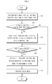
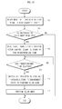
- FIG. 4 is a flowchart of a control method of the image forming apparatus in accordance with an embodiment.
- the controller 202 executes contact between the transfer belt 51 and the BK photoconductor 31 by pressing the transfer belt 51 using the transfer roller 54 corresponding to black (BK) (Operation 402).
- the controller 202 confirms whether or not switching from the mono mode to the color mode is required (Operation 404).
- switching to the color mode may be executed to perform image formation in the color mode, or be executed to go through the color mode for switching to the ready mode.
- the controller 202 deactivates a transfer belt driving motor control signal so as to stop rotation of the transfer belt driving motor 206, and, for this purpose, stands by (waits) for a predetermined time (Operation 406).
- the transfer belt driving motor control signal is deactivated, rotation of the transfer belt 51 is stopped.
- the transfer belt driving motor 206 is not immediately stopped. Instead, the transfer belt driving motor 206 continues to rotate for a designated time due to rotational inertia and is then stopped. Therefore, the controller 202 stands by (waits) for the predetermined time ( ⁇ ms) until rotational inertia of the transfer belt driving motor 206 is completely eliminated ('No' in Operation 408).
- the controller 202 switches three transfer rollers 54 and three photoconductors 31 corresponding to cyan (C), magenta (M), and yellow (Y) to form a color image to the engagement state by activating the engagement driving control signal (Operation 410). Because the rotation of the transfer belt driving motor 206 has completely stopped, three transfer rollers 54 and three photoconductors 31 corresponding to cyan (C), magenta (M), and yellow (Y) can now be switched to the engagement state, so that no problem occurs in the color mode.
- the predetermined time ( ⁇ ms) may be determined using the following method.
- a time taken to completely stop the transfer belt driving motor 206 from a point of time when the stop instructions are generated is calculated in advance through experimentation, and the calculated time is set as the predetermined time ( ⁇ ms) so that the controller 202 may refer to the predetermined time ( ⁇ ms).
- the controller 202 may refer to the predetermined time ( ⁇ ms).
- other methods, through which the time taken to completely stop the transfer belt driving motor 206 from the point of time when the stop instructions are generated may be predicted or measured may be used. For example, instead of setting of the predetermined time ( ⁇ ms), complete stoppage of rotation of the transfer belt driving motor 206 may be actually measured from rotating state information of the transfer belt driving motor 206.
- the controller 202 activates the engagement driving motor control signal so that the transfer rollers 54 press the transfer belt 51 and thus the engagement state in which the transfer belt 51 contacts all the photoconductors 31 is formed so as to perform image formation in the color mode (Operation 412).
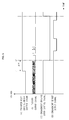
- FIG. 5 is a graph illustrating waveforms of the image forming apparatus in accordance with an embodiment.
- (A) is a transfer belt driving motor control signal to control the transfer belt driving motor 206.
- (B) is an encoder output signal representing rotating state information (speed and rate of rotation, etc.) of the transfer belt driving motor 206.
- (C) is an engagement driving motor control signal to change the positions of the transfer rollers 54 to control switching between the engagement state and the disengagement state.
- (D) is an engagement sensor output signal representing engagement state information of the transfer rollers 54.
- the controller 202 deactivates the transfer belt driving motor control signal (t1).
- the reason why rotation of the transfer roller 54 corresponding to black is stopped at the point of time (t1) is to switch from the mono mode to the color mode.
- the transfer belt driving motor control signal is deactivated, rotation of the transfer belt 51 is stopped.
- the transfer belt driving motor 206 is not immediately stopped at the point of time (t1), but continues to rotate for a designated time due to rotational inertia and is then stopped. From the encoder output signal (B) in FIG.
- the transfer belt driving motor 206 is rotated for a designated time ( ⁇ ms) after the point of time (t1).
- the controller 202 switches three transfer rollers 54 and three photoconductors 31 corresponding to cyan (C), magenta (M), and yellow (Y) to form a color image into the engagement state by activating the engagement driving control signal (t2).
- the controller 202 switches three transfer rollers 54 and three photoconductors 31 corresponding to cyan (C), magenta (M), and yellow (Y) to form a color image into the engagement state by activating the engagement driving control signal (t2).
- the controller 202 switches three transfer rollers 54 and three photoconductors 31 corresponding to cyan (C), magenta (M), and yellow (Y) to form a color image into the engagement state by activating the engagement driving control signal (t2).
- the controller 202 switches three transfer rollers 54 and three photoconductors 31 corresponding to cyan (C), magenta (M), and yellow (Y) to form a color image into the engagement state by
- the controller 202 confirms whether or not a predetermined time ( ⁇ ms) after the point of time (t1) when the transfer belt driving motor control signal is deactivated has elapsed, and judges that rotation of the transfer belt driving motor 206 by rotational inertia is completely stopped if it is confirmed that the predetermined time ( ⁇ ms) has elapsed.
- the predetermined time ( ⁇ ms) is determined through the following method.
- a time taken to completely stop the transfer belt driving motor 206 from a point of time when the stop instructions are generated is calculated in advance through experimentation, and the calculated time is set as the predetermined time ( ⁇ ms) so that the controller 202 may refer to the predetermined time ( ⁇ ms).
- the controller 202 may refer to the predetermined time ( ⁇ ms).
- other methods through which the time taken to completely stop the transfer belt driving motor 206 from the point of time when the stop instructions are generated may be predicted or measured, may be used.
- complete stoppage of rotation of the transfer belt driving motor 206 may be actually measured from rotating state information of the transfer belt driving motor 206.
- the controller 202 activates the engagement driving motor control signal so as to form the engagement state of the transfer rollers 54 to perform the color mode.
- FIG. 6 is a view illustrating a control system of an image forming apparatus in accordance with an embodiment.
- a controller 502 controlling the overall operation of an image forming apparatus 100 is electrically connected to a photoconductor driving motor 504, a transfer belt driving motor 506, and an engagement driving motor 508 so as to be communicable with the photoconductor driving motor 504, the transfer belt driving motor 506, and the engagement driving motor 508.
- the controller 502 participates in rotation and stoppage of the photoconductors 31 through control of the photoconductor driving motor 504. Further, the controller 502 participates in rotation and stoppage of the driving roller 52 and the transfer belt 51 through control of the transfer belt driving motor 506.
- 'engagement' refers to a state in which the transfer roller 54 presses the transfer belt 51 and thus the transfer belt 51 contacts the photoconductor 31
- 'disengagement' refers to a state in which pressing of the transfer belt 51 by the transfer roller 54 is released and thus contact between the transfer belt 51 and the photoconductor 31 is released (with reference to FIGS. 3(A) to 3(C) ). All the four transfer rollers 54 and all the four photoconductors 31 may be engaged with or disengaged from each other, or some of the four transfer rollers 54 and some of the four photoconductors 31 may be engaged with or disengaged from each other.
- the controller 502 is electrically connected to an engagement sensor 510 and an encoder 512 so as to be communicable with the engagement sensor 510 and the encoder 512.
- the engagement sensor 510 serves to detect the engagement states and disengagement states among the transfer rollers 54 and the transfer belt 51 and photoconductors 31, detects the engagement states and disengagement states of the transfer rollers 54, and provides the detected state information to the controller 502.
- the encoder 512 is an encoder of the transfer belt driving motor 506, detects the rotating state of the transfer belt driving motor 506, and provides the rotating state information to the controller 502.
- a transfer belt braking part 514 is provided in the transfer belt driving motor 506.
- the transfer belt braking part 514 generates braking force of the transfer belt driving motor 506 when the transfer belt driving motor 506 is stopped, and thus shortens a time taken to eliminate rotational inertia so that the transfer belt driving motor 506 may be stopped more quickly (in a shorter time).
- the transfer belt braking part 514 may be configured to apply braking force directly to the driving roller 52 rotating the transfer belt 51, instead of applying braking force to the transfer belt driving motor 506.
- the controller 502 may greatly shorten a time taken to completely stop rotation of the transfer belt driving motor 506 in the rotating state by applying braking force to the transfer belt driving motor 506 through the transfer belt braking part 514 when the transfer belt driving motor 506 is stopped.
- FIG. 7 is a flowchart of a control method of the image forming apparatus in accordance with an embodiment.
- the controller 502 executes contact between the transfer belt 51 and the BK photoconductor 31 by pressing the transfer belt 51 using the transfer roller 54 corresponding to black (BK) (Operation 702).
- the controller 502 confirms whether or not switching from the mono mode to the color mode is required (Operation 704).
- switching to the color mode may be executed to perform image formation in the color mode, or be executed to go through the color mode for switching to the ready mode.
- the controller 502 deactivates a transfer belt driving motor control signal so as to stop rotation of the transfer belt driving motor 506, performs braking of the transfer belt driving motor 506 to shorten a time taken to stop rotation of the transfer belt driving motor 506, and stands by for a predetermined time until rotation of the transfer belt driving motor 506 is decelerated within a short time by braking (Operation 706).
- the transfer belt driving motor control signal is deactivated, rotation of the transfer belt 51 is stopped. At this time, the transfer belt driving motor 506 is not immediately stopped, but continues to rotate for a designated time due to rotational inertia and is then stopped.
- the controller 502 stands by for the predetermined time ( ⁇ ms) until rotational inertia of the transfer belt driving motor 506 is completely eliminated ('No' in Operation 708).
- the controller 502 switches three transfer rollers 54 and three photoconductors 31 corresponding to cyan (C), magenta (M), and yellow (Y) to form a color image to the engagement state by activating the engagement driving control signal (Operation 710).
- the predetermined time ( ⁇ ms) is determined through the following method. That is, a time taken to completely stop the transfer belt driving motor 206 from a point of time when the stop instructions are generated is calculated in advance through experimentation, and the calculated time is set as the predetermined time ( ⁇ ms) so that the controller 502 may refer to the predetermined time ( ⁇ ms).
- FIG. 8 is a graph illustrating waveforms of the image forming apparatus in accordance with an embodiment.
- (A) is a transfer belt driving motor control signal to control the transfer belt driving motor 506.
- (B) is an encoder output signal representing rotating state information (speed and rate of rotation, etc.) of the transfer belt driving motor 506.
- (C) is an engagement driving motor control signal to change the positions of the transfer rollers 54 to control switching between the engagement state and the disengagement state.
- (D) is an engagement sensor output signal representing engagement state information of the transfer rollers 54.
- the controller 502 deactivates the transfer belt driving motor control signal (t1).
- the reason why rotation of the transfer roller 54 corresponding to black is stopped at the point of time (t1) is to switch from the mono mode to the color mode.
- the transfer belt driving motor control signal is deactivated, rotation of the transfer belt 51 is stopped.
- the transfer belt driving motor 506 is not immediately stopped at the point of time (t1), but continues to rotate for a designated time due to rotational inertia and is then stopped. From the encoder output signal (B) in FIG.
- the transfer belt driving motor 506 is rotated for a designated time ( ⁇ ms) after the point of time (t1). Upon judging that rotation of the transfer belt driving motor 506 by rotational inertia is completely stopped, the controller 502 switches three transfer rollers 54 and three photoconductors 31 corresponding to cyan (C), magenta (M), and yellow (Y) to form a color image to the engagement state by activating the engagement driving control signal at a point of time (t2).
- the controller 502 confirms whether or not a predetermined time ( ⁇ ms) after the point of time (t1) when the transfer belt driving motor control signal is deactivated has elapsed, and judges that rotation of the transfer belt driving motor 506 by rotational inertia is completely stopped if it is confirmed that the predetermined time ( ⁇ ms) has elapsed.
- the predetermined time ( ⁇ ms) is determined through the following method. That is, a time taken to completely stop the transfer belt driving motor 506 from a point of time when the stop instructions are generated is calculated in advance through experimentation, and the calculated time is set as the predetermined time ( ⁇ ms) so that the controller 502 may refer to the predetermined time ( ⁇ ms).
- other methods through which the time taken to completely stop the transfer belt driving motor 506 from the point of time when the stop instructions are generated may be predicted or measured, may be used. For example, instead of setting of the predetermined time ( ⁇ ms), complete stoppage of rotation of the transfer belt driving motor 506 may be actually measured from rotating state information of the transfer belt driving motor 506. When complete stoppage of rotation of the transfer belt driving motor 506 is measured, the controller 502 activates the engagement driving motor control signal so as to form the engagement state of the transfer rollers 54 to perform the color mode.
- the time (t2-t1) taken to judge that rotation of the transfer belt driving motor 206 is completely stopped (t2) from the point of time (t1) when the stop instructions are generated, in FIG. 8 is shorter than the time (t2-t1) in FIG. 5 .
- the reason for this is that the transfer belt driving motor 506 or the driving roller 502 in the rotating state may more quickly reach the stoppage state by the braking action of the transfer belt braking part 514 in the control system of the image forming apparatus in accordance with an embodiment shown in FIG. 7 .
- FIG. 9 is a flowchart of a control method of an image forming apparatus in accordance with an embodiment.
- the control method shown in FIG. 9 serves to prevent generation of unexpected operation under the contact state between the transfer belt 51 and the photoconductors 31 when the precise engage/disengagement state of the transfer rollers 54 prior to being powered on of the image forming apparatus is not confirmed, if the image forming apparatus is first preheated so as to perform image formation after being powered on.
- the transfer rollers 54 are forcibly disengaged (Operation 904).
- the reason why the transfer rollers 54 are forcibly disengaged before first warm-up after being powered on is performed is that whether or not the current transfer roller 54 is in the engagement state or the disengagement state is not confirmed at a point of time just after being powered on.
- transfer rollers 54 are in the disengagement state after being powered on, no problem occurs. However, if the transfer rollers 54 are in the engagement state after being powered on, driving of the transfer belt 51 and the photoconductors 31 in the engagement state of the transfer rollers 54 may cause an unintended result.
- the image forming apparatus may cope with various unpredictable situations including the cases 1 to 3 and thus perform stable image formation.
- FIG. 10 is a view illustrating a control system of an image forming apparatus in accordance with an embodiment.
- a controller 1002 controlling the overall operation of an image forming apparatus 100 is electrically connected to a photoconductor driving motor 1004, a transfer belt driving motor 1006, and an engagement driving motor 1008 so as to be communicable with the photoconductor driving motor 1004, the transfer belt driving motor 1006, and the engagement driving motor 1008.
- the controller 1002 participates in rotation and stoppage of the photoconductors 31 through control of the photoconductor driving motor 1004. Further, the controller 1002 participates in rotation and stoppage of the driving roller 52 and the transfer belt 51 through control of the transfer belt driving motor 1006.
- controller 1002 participates in engagement and disengagement of the transfer rollers 54 through control of the engagement driving motor 1008.
- 'engagement' refers to a state in which the transfer roller 54 presses the transfer belt 51 and thus the transfer belt 51 contacts the photoconductor 31
- 'disengagement' refers to a state in which pressing of the transfer belt 51 by the transfer roller 54 is released and thus contact between the transfer belt 51 and the photoconductor 31 is released (with reference to FIGS. 11(A) and 11(B) ).
- the controller 1002 is electrically connected to an engagement sensor 1010 and an encoder 1012 so as to be communicable with the engagement sensor 1010 and the encoder 1012.
- the engagement sensor 1010 serves to detect the engagement states and disengagement states among the transfer rollers 54 and the transfer belt 51 and photoconductors 31, detects the engagement states and disengagement states of the transfer rollers 54, and provides the detected state information to the controller 1002.
- the encoder 1012 is an encoder of the transfer belt driving motor 1006, detects the rotating state of the transfer belt driving motor 1006, and provides the rotating state information to the controller 1002.
- FIGS. 11(A) and 11(B) are views illustrating operating modes regarding a transfer device and the photoconductors of the image forming apparatus shown in FIG. 10 .
- FIG. 11(A) illustrates a ready mode prior to image formation.
- the ready mode all the transfer rollers 54, the transfer belt 51, and all the opposite photoconductors 31 are disengaged from one another.
- opposite refers to the four transfer rollers 54 and the four photoconductors 31 corresponding to each other.
- image formation is not carried out, and thus, the disengagement state between the all the transfer rollers 54 and the all the photoconductors 31 is maintained.
- FIG. 11(B) illustrates a color mode in which a color image is formed using black (BK), cyan (C), magenta (M), and yellow (Y) developing agents.
- black (BK), cyan (C), magenta (M), and yellow (Y) developing agents.
- all the four transfer rollers 54, the transfer belt 51, and all the four photoconductors 31 corresponding to black (BK), cyan (C), magenta (M), and yellow (Y) are engaged with one another.
- black (BK), cyan (C), magenta (M), and yellow (Y) participate in image formation, all the four transfer rollers 54 and all the four photoconductors 31 are rotated.
- the ready mode and the color mode may be switched in the order of '... ⁇ ready mode ⁇ color mode ⁇ ready mode ⁇ color mode ⁇ ...'.
- the disengagement state between all the transfer rollers 54 and all the photoconductors 31, as exemplarily shown in FIG. 11(A) is switched to the engagement state between the four transfer rollers 54 and the four photoconductors 31 corresponding to black (BK), cyan (C), magenta (M), and yellow (Y) to form a color image, as exemplarily shown in FIG. 11(B) .
- BK black
- C cyan
- M magenta
- Y yellow
- the transfer rollers 54 are switched to the engagement state under the condition that the transfer belt driving motor 1006 is not immediately stopped but is rotated for a designated time due to rotational inertia, a band-shaped image may be formed on the transfer rollers 54 due to contact between the transfer belt 51 rotated by rotational inertia of the transfer belt driving motor 1006 and the transfer rollers 54 engaged therewith, and such an image may have an unintended influence on an image on a printing medium.
- FIG. 12 is a flowchart of a control method of the image forming apparatus in accordance with an embodiment.
- the controller 1002 switches all the transfer rollers 54 to the disengagement state (Operation 1202).
- the controller 1002 confirms whether or not switching from the ready mode to the color mode is required (Operation 1204).
- switching to the color mode may be executed to perform image formation in the color mode.
- the controller 1002 deactivates a transfer belt driving motor control signal so as to stop rotation of the transfer belt driving motor 1006, and, for this purpose, stands by for a predetermined time (Operation 1206).
- the transfer belt driving motor control signal is deactivated, rotation of the transfer belt 51 is stopped. At this time, the transfer belt driving motor 1006 is not immediately stopped, but continues to rotate for a designated time due to rotational inertia and is then stopped. Therefore, the controller 1002 stands by for the predetermined time ( ⁇ ms) until rotational inertia of the transfer belt driving motor 1006 is completely eliminated ('No' in Operation 1208).
- the controller 1002 switches four transfer rollers 54 and four photoconductors 31 corresponding to black (BK), cyan (C), magenta (M), and yellow (Y) to form a color image to the engagement state by activating the engagement driving control signal (Operation 1210).
- the controller 1002 since rotation of the transfer belt driving motor 1006 is completely stopped, although four transfer rollers 54 and four photoconductors 31 corresponding to black (BK), cyan (C), magenta (M), and yellow (Y) are switched to the engagement state, no problem occurs.
- the predetermined time ( ⁇ ms) is determined through the following method. That is, a time taken to completely stop the transfer belt driving motor 1006 from a point of time when the stop instructions are generated is calculated in advance through experimentation, and the calculated time is set as the predetermined time ( ⁇ ms) so that the controller 1002 may refer to the predetermined time ( ⁇ ms).
- the predetermined time ⁇ ms
- other methods through which the time taken to completely stop the transfer belt driving motor 1006 from the point of time when the stop instructions are generated may be predicted or measured, may be used. For example, instead of setting of the predetermined time ( ⁇ ms), complete stoppage of rotation of the transfer belt driving motor 1006 may be actually measured from rotating state information of the transfer belt driving motor 1006.
- the controller 1002 activates the engagement driving motor control signal so that the transfer rollers 54 press the transfer belt 51 and thus the engagement state in which the transfer belt 51 contacts all the photoconductors 31 is formed so as to perform image formation in the color mode (Operation 1212).
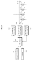
- FIG. 13 is a view illustrating a control system of an image forming apparatus in accordance with an embodiment.
- a controller 1302 controlling the overall operation of an image forming apparatus 100 is electrically connected to a photoconductor driving motor 1304, a transfer belt driving motor 1306, and an engagement driving motor 1308 so as to be communicable with the photoconductor driving motor 1304, the transfer belt driving motor 1306, and the engagement driving motor 1308.
- the controller 1302 participates in rotation and stoppage of the photoconductors 31 through control of the photoconductor driving motor 1304. Further, the controller 1302 participates in rotation and stoppage of the driving roller 52 and the transfer belt 51 through control of the transfer belt driving motor 1306.
- controller 1302 participates in engagement and disengagement of the transfer rollers 54 through control of the engagement driving motor 1308.
- 'engagement' refers to a state in which the transfer roller 54 presses the transfer belt 51 and thus the transfer belt 51 contacts the photoconductor 31
- 'disengagement' refers to a state in which pressing of the transfer belt 51 by the transfer roller 54 is released and thus contact between the transfer belt 51 and the photoconductor 31 is released (with reference to FIGS. 14(A) and 14(B) ). All the four transfer rollers 54 and all the four photoconductors 31 may be engaged with or disengaged from each other, or some of the four transfer rollers 54 and some of the four photoconductors 31 may be engaged with or disengaged from each other.
- the controller 1302 is electrically connected to an engagement sensor 1310 and an encoder 1312 so as to be communicable with the engagement sensor 1310 and the encoder 1312.
- the engagement sensor 1310 serves to detect the engagement states and disengagement states among the transfer rollers 54 and the transfer belt 51 and photoconductors 31, detects the engagement states and disengagement states of the transfer rollers 54, and provides the detected state information to the controller 1302.
- the encoder 1312 is an encoder of the transfer belt driving motor 1306, detects the rotating state of the transfer belt driving motor 1306, and provides the rotating state information to the controller 1302.
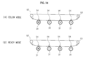
- FIGS. 14(A) and 14(B) are views illustrating operating modes regarding a transfer device and the photoconductors of the image forming apparatus shown in FIG. 13 .
- FIG. 14(A) illustrates a color mode in which a color image is formed using black (BK), cyan (C), magenta (M), and yellow (Y) developing agents.
- BK black
- C cyan
- M magenta
- Y yellow
- all the four transfer rollers 54, the transfer belt 51, and all the four photoconductors 31 corresponding to black (BK), cyan (C), magenta (M), and yellow (Y) are engaged with one another.
- black (BK), cyan (C), magenta (M), and yellow (Y) participate in image formation, all the four transfer rollers 54 and all the four photoconductors 31 are rotated.
- FIG. 14(B) illustrates a ready mode prior to image formation.
- the ready mode all the transfer rollers 54, the transfer belt 51, and all the opposite photoconductors 31 are disengaged from one another.
- opposite refers to the four transfer rollers 54 and the four photoconductors 31 corresponding to each other.
- image formation is not carried out, and thus, the disengagement state between the all the transfer rollers 54 and the all the photoconductors 31 is maintained.
- the ready mode and the color mode may be switched in the order of '... ⁇ ready mode ⁇ color mode ⁇ ready mode ⁇ color mode ⁇ ...'.
- the engagement state between all the transfer rollers 54 and all the photoconductors 31, as exemplarily shown in FIG. 14(A) is switched to the disengagement state between the four transfer rollers 54 and the four photoconductors 31 corresponding to black (BK), cyan (C), magenta (M), and yellow (Y) to form a color image, as exemplarily shown in FIG. 14(B) .
- BK black
- C cyan
- M magenta
- Y yellow
- a band-shaped image may be formed on the transfer rollers 54 due to triboelectrification between the transfer belt 51 and the photoconductors 31 at a point of time when contact between the transfer belt 51, rotated due to rotational inertia of the transfer belt driving motor 1306, and the transfer rollers 54 disengaged therefrom is released, and such an image may have an unintended influence on an image on a printing medium.
- FIG. 15 is a flowchart of a control method of the image forming apparatus in accordance with an embodiment.
- the controller 1302 switches all the transfer rollers 54 to the engagement state (Operation 1502).
- the controller 1302 confirms whether or not switching from the color mode to the ready mode is required (Operation 1504).
- the controller 1302 deactivates a transfer belt driving motor control signal so as to stop rotation of the transfer belt driving motor 1306, and, for this purpose, stands by for a predetermined time (Operation 1506). As the transfer belt driving motor control signal is deactivated, rotation of the transfer belt 51 is stopped.
- the transfer belt driving motor 1306 is not immediately stopped, but continues to rotate for a designated time due to rotational inertia and is then stopped. Therefore, the controller 1302 stands by for the predetermined time ( ⁇ ms) until rotational inertia of the transfer belt driving motor 1306 is completely eliminated ('No' in Operation 1508).
- the controller 1302 switches four transfer rollers 54 and four photoconductors 31 corresponding to black (BK), cyan (C), magenta (M), and yellow (Y) to the disengagement state by deactivating the engagement driving control signal (Operation 1510).
- the predetermined time ( ⁇ ms) is determined through the following method. That is, a time taken to completely stop the transfer belt driving motor 1306 from a point of time when the stop instructions are generated is calculated in advance through experimentation, and the calculated time is set as the predetermined time ( ⁇ ms) so that the controller 1302 may refer to the predetermined time ( ⁇ ms).
- transfer rollers press a transfer belt after stoppage of the transfer belt if the transfer rollers presses the transfer belt to cause the transfer belt to contact photoconductors, and thus contact between the transfer belt in the rotating state and the photoconductors may be prevented, thus preventing damage to the transfer belt, the transfer rollers, and the photoconductors and preventing contamination of a printed matter due to triboelectrification caused by contact between the transfer belt in the rotating state and the photoconductors.
Landscapes
- Physics & Mathematics (AREA)
- General Physics & Mathematics (AREA)
- Color Electrophotography (AREA)
- Electrostatic Charge, Transfer And Separation In Electrography (AREA)
Abstract
Description
- Embodiments relate to an image forming apparatus having a transfer device transferring developing agents from a plurality of developing units to paper, and a control method thereof.
- An electrophotographic image forming apparatus, for example, a laser printer, a digital copier, or a multi-function apparatus, refers to an apparatus which radiates light to photoconductors charged with a designated electric potential to form electrostatic latent images on the outer surfaces of the photoconductors, supplies toners, i.e., developing agents, to the electrostatic latent images to form visible images, and transfers and fixes the visible images to a printing medium to print the images.
- A color image forming apparatus includes a plurality of photoconductors converting electrostatic latent images into visible images through developing agents, a transfer belt to which the visible images formed by the plurality of photoconductors are transferred, a transfer belt driving motor to rotate the transfer belt, and a plurality of transfer rollers pressing the transfer belt toward the photoconductors and causing the transfer belt to come into contact with the photoconductors so as to transfer the visible images on the photoconductors to the transfer belt.
- If the transfer belt in the rotating state contacts the photoconductors when one or more transfer rollers press the transfer belt so as to achieve contact between the transfer belt and the photoconductors, the transfer belt, the transfer rollers, and the photoconductors may be damaged, and a printed matter may be contaminated due to triboelectrification caused by contact between the transfer belt in the rotating state and the photoconductors.
- According to the present invention there is provided an apparatus and method as set forth in the appended claims. Other features of the invention will be apparent from the dependent claims, and the description which follows.
- In an aspect of one or more embodiments, there is provided an image forming apparatus and a control method thereof in which a transfer roller presses a transfer belt after stoppage of the transfer belt if the transfer roller presses the transfer belt to come into contact with a photoconductor, and thus contact between the transfer belt in the rotating state and the photoconductor may be prevented.
- In an aspect of one or more embodiments, there is provided a control method of an image forming apparatus which has a plurality of transfer rollers arranged in parallel with a plurality of photoconductors such that a transfer belt is interposed between the plurality of transfer rollers and the plurality of photoconductors and pressing the transfer belt to come into contact with the plurality of photoconductors, includes rotating the transfer belt under the condition that the plurality of transfer rollers does not press the transfer belt toward the plurality of photoconductors, interrupting power transmitted to the transfer belt to cause the plurality of transfer rollers to press the transfer belt, standing by until rotation of the transfer belt is stopped, after interruption of the power, and controlling the plurality of transfer rollers so as to press the transfer belt toward the plurality of photoconductors, when rotation of the transfer belt is stopped.
- The standing by may be carried out for a predetermined time until rotation of the transfer belt is stopped.
- The predetermined time may be time for which the transfer belt is rotated due to rotational inertia after interruption of the power transmitted to the transfer belt.
- In a ready mode, the pressing state of the plurality of transfer rollers may be released so that all of the plurality of transfer rollers does not contact the plurality of photoconductors, and in a color mode, transfer rollers participating in formation of a color image among the plurality of transfer rollers may press the transfer belt so as to contact corresponding photoconductors.
- In an aspect of one or more embodiments, there is provided a control method of an image forming apparatus which has a plurality of transfer rollers arranged in parallel with a plurality of photoconductors such that a transfer belt is interposed between the plurality of transfer rollers and the plurality of photoconductors and pressing the transfer belt to come into contact with the plurality of photoconductors, includes rotating the transfer belt under the condition that the plurality of transfer rollers presses the transfer belt toward the plurality of photoconductors, interrupting power transmitted to the transfer belt to release the pressed state of the transfer belt by the plurality of transfer rollers, standing by until rotation of the transfer belt is stopped, after interruption of the power, and releasing the pressed state of the transfer belt by the plurality of transfer rollers, when rotation of the transfer belt is stopped.
- The standing by may be carried out for a predetermined time until rotation of the transfer belt is stopped.
- The predetermined time may be time taken to stop rotation of the transfer belt due to rotational inertia after interruption of the power transmitted to the transfer belt.
- In a ready mode, the pressing state of the plurality of transfer rollers may be released so that all of the plurality of transfer rollers does not contact the plurality of photoconductors, and in a color mode, transfer rollers participating in formation of a color image among the plurality of transfer rollers may press the transfer belt so as to contact corresponding photoconductors.
- In an aspect of one or more embodiments, there is provided a control method of an image forming apparatus which has a plurality of transfer rollers arranged in parallel with a plurality of photoconductors such that a transfer belt is interposed between the plurality of transfer rollers and the plurality of photoconductors and pressing the transfer belt to come into contact with the plurality of photoconductors, includes rotating the transfer belt under the condition that at least one of the plurality of transfer rollers presses the transfer belt toward at least one of the plurality of photoconductors, interrupting power transmitted to the transfer belt to cause at least another of the plurality of transfer rollers to press the transfer belt toward at least another of the plurality of photoconductors, standing by until rotation of the transfer belt is stopped, after interruption of the power, and controlling the at least another of the plurality of transfer rollers so as to press the transfer belt toward the at least another of the plurality of photoconductors, when until rotation of the transfer belt is stopped.
- The standing by may be carried out for a predetermined time until rotation of the transfer belt is stopped.
- The predetermined time may be time taken to stop rotation of the transfer belt due to rotational inertia after interruption of the power transmitted to the transfer belt.
- In a ready mode, the pressing state of the plurality of transfer rollers may be released so that all of the plurality of transfer rollers does not contact the plurality of photoconductors, in a mono mode, only a transfer roller participating in formation of a mono image among the plurality of transfer rollers may press the transfer belt so as to contact a corresponding photoconductor, and in a color mode, transfer rollers participating in formation of a color image among the plurality of transfer rollers may press the transfer belt so as to contact corresponding photoconductors.
- Mode switching may be carried out in the order of the ready mode, the mono mode, and the color mode.
- In an aspect of one or more embodiments, there is provided an image forming apparatus includes a plurality of photoconductors, a transfer belt, a plurality of transfer rollers arranged in parallel with the plurality of photoconductors such that the transfer belt is interposed between the plurality of transfer rollers and the plurality of photoconductors and pressing the transfer belt to come into contact with the plurality of photoconductors, and a controller rotating the transfer belt under the condition that at least one of the plurality of transfer rollers presses the transfer belt toward at least one of the plurality of photoconductors, interrupting power transmitted to the transfer belt to cause at least another of the plurality of transfer rollers to press the transfer belt toward at least another of the plurality of photoconductors, standing by until rotation of the transfer belt is stopped, after interruption of the power, and controlling the at least another of the plurality of transfer rollers so as to press the transfer belt toward the at least another of the plurality of photoconductors.
- The controller may stand by for a predetermined time until rotation of the transfer belt is stopped.
- The predetermined time may be time taken to stop rotation of the transfer belt due to rotational inertia after interruption of the power transmitted to the transfer belt.
- In a ready mode, the pressing state of the plurality of transfer rollers may be released so that all of the plurality of transfer rollers does not contact the plurality of photoconductors, in a mono mode, only a transfer roller participating in formation of a mono image among the plurality of transfer rollers may press the transfer belt so as to contact a corresponding photoconductor, and in a color mode, transfer rollers participating in formation of a color image among the plurality of transfer rollers may press the transfer belt so as to contact corresponding photoconductors.
- Mode switching may be carried out in the order of the ready mode, the mono mode, and the color mode.
- In an aspect of one or more embodiments, there is provided a control method of an image forming apparatus which has a plurality of transfer rollers arranged in parallel with a plurality of photoconductors such that a transfer belt is interposed between the plurality of transfer rollers and the plurality of photoconductors and pressing the transfer belt to come into contact with the plurality of photoconductors, includes forcibly releasing the contact state between the transfer belt and the plurality of photoconductors by pressing the transfer belt using the plurality of transfer rollers, before first warm-up after being powered-on of the image forming apparatus is performed, and performing the first warm-up, when the contact state between the transfer belt and the plurality of photoconductors is released.
- In an aspect of one or more embodiments, there is provided an image forming apparatus includes a plurality of photoconductors, a transfer belt, a plurality of transfer rollers arranged in parallel with the plurality of photoconductors such that the transfer belt is interposed between the plurality of transfer rollers and the plurality of photoconductors and pressing the transfer belt to come into contact with the plurality of photoconductors, and a controller forcibly releasing the contact state between the transfer belt and the plurality of photoconductors by pressing the transfer belt through the plurality of transfer rollers, before first warm-up after being powered on of the image forming apparatus is performed.
- The controller may perform the first warm-up, when the contact state between the transfer belt and the plurality of photoconductors is released.
- In an aspect of one or more embodiments, there is provided a control method of an image forming apparatus which has a plurality of transfer rollers arranged in parallel with a plurality of photoconductors such that a transfer belt is interposed between the plurality of transfer rollers and the plurality of photoconductors and pressing the transfer belt to come into contact with the plurality of photoconductors, includes rotating the transfer belt under the condition that the plurality of transfer rollers does not press the transfer belt toward the plurality of photoconductors, interrupting power transmitted to the transfer belt to cause the plurality of transfer rollers to press the transfer belt, reducing the rotational speed of the transfer belt due to rotational inertia by controlling a transfer belt braking part, standing by until rotation of the transfer belt is stopped, and controlling the plurality of transfer rollers so as to press the transfer belt toward the plurality of photoconductors or to release the pressed state of the transfer belt by the plurality of transfer rollers, when rotation of the transfer belt is stopped.
- The transfer belt braking part may serve to reduce the rotational speed of a transfer belt driving motor to rotate the transfer belt.
- The transfer belt braking part may serve to reduce the rotational speed of a driving roller to rotate the transfer belt.
- These and/or other aspects of embodiments will become apparent and more readily appreciated from the following description of embodiments, taken in conjunction with the accompanying drawings of which:
-
FIG. 1 is a sectional view of an image forming apparatus in accordance with an embodiment; -
FIG. 2 is a view illustrating a control system of an image forming apparatus in accordance with an embodiment; -
FIGS. 3(A) to 3(C) are views illustrating operating modes regarding a transfer device and photoconductors of the image forming apparatus shown inFIG. 1 ; -
FIG. 4 is a flowchart of a control method of the image forming apparatus in accordance with an embodiment shown inFIG. 2 ; -
FIG. 5 is a graph illustrating waveforms (A) through (D) of the image forming apparatus in accordance with an embodiment; -
FIG. 6 is a view illustrating a control system of an image forming apparatus in accordance with an embodiment; -
FIG. 7 is a flowchart of a control method of the image forming apparatus in accordance with an embodiment; -
FIG. 8 is a graph illustrating waveforms (A) through (D) of the image forming apparatus in accordance with an embodiment; -
FIG. 9 is a flowchart of a control method of an image forming apparatus in accordance with an embodiment; -
FIG. 10 is a view illustrating a control system of an image forming apparatus in accordance with an embodiment; -
FIGS. 11(A) and 11(B) are views illustrating operating modes regarding a transfer device and photoconductors of the image forming apparatus shown inFIG. 10 ; -
FIG. 12 is a flowchart of a control method of the image forming apparatus in accordance with an embodiment; -
FIG. 13 is a view illustrating a control system of an image forming apparatus in accordance with an embodiment; -
FIGS. 14(A) and 14(B) are views illustrating operating modes regarding a transfer device and photoconductors of the image forming apparatus shown inFIG. 13 ; and -
FIG. 15 is a flowchart of a control method of the image forming apparatus in accordance with an embodiment. - Reference will now be made in detail to embodiments, examples of which are illustrated in the accompanying drawings, wherein like reference numerals refer to like elements throughout.
-
FIG. 1 is a sectional view of an image forming apparatus in accordance with an embodiment. As exemplarily shown inFIG. 1 , animage forming apparatus 100 in accordance with an embodiment includes amain body 10 forming the external appearance of theimage forming apparatus 100, a printingmedium storage unit 20 in which printing media are stored, a plurality of developing units (developers) 30C, 30M, 30Y, and 30K developing electrostatic latent images into visible images according to color through developing agents (for example, toners), anexposure unit 40 radiating light tophotoconductors 31 of the charged developingunits first transfer unit 50 receiving a printing medium from the printingmedium storage unit 20 and asecond transfer unit 60 transferring the visible images formed on the photoconductors to the printing medium, and afixing unit 70 fixing the developing agents, transferred to the printing medium, to the printing medium. - The
main body 10 is provided with aload part 10a, on which printing media having completed image formation loaded. Theload part 10a is formed on the upper portion of themain body 10. Anexit hole 10b through which the printing media having completed image formation exits themain body 10 is provided at one side of theload part 10a. An opening 10c to repair and replace parts within themain body 10 or to replace consumables within themain body 10 is provided at one side of themain body 10, and aside cover 11 to open and close the opening 10c is installed. In an embodiment, theside cover 11 is configured such that the lower end of theside cover 11 is rotatably installed on themain body 10, and is rotated about the lower end of theside cover 11, thus opening and closing the opening 10c. - The printing
medium storage unit 20 includes aprinting medium cassette 21 movably installed on themain body 10, a knock-upplate 22 arranged within theprinting medium cassette 21 such that the printing media are loaded on the knock-upplate 22, and anelastic member 23 elastically supporting the knock-upplate 22. - Each of the developing
units photoconductor 31 provided with the charged surface on which an electrostatic latent image is formed by theexposure unit 40, a developingroller 32 supplying the developing agent to thephotoconductor 31, and acharging unit 33 charging the surface of thephotoconductor 31. - In an embodiment, four developing
units units - The
exposure unit 40 radiates light containing image information to thephotoconductors 31 of the developingunits photoconductors 31. - The transfer device includes a
first transfer unit 50 to which the visible images formed by the developing agents from the developingunits second transfer unit 60 transferring the visible images on thefirst transfer unit 50 to a printing medium. - The fixing
unit 70 includes aheating roller 71 generating heat, and apressure roller 72 provided with an outer circumferential surface formed of an elastically deformable material and pressing a printing medium to the outer circumferential surface of theheating roller 71. - Further, a pick-up
unit 80 arranged on the printingmedium storage unit 20 to pick up the printing media loaded on the knock-upplate 22 sheet by sheet, feedrollers 12 guiding the printing media picked up by the pick-upunit 80 upwardly, and anexit unit 90 located above the fixingunit 70 and arranged adjacent to theexit holt 10b to discharge the printing medium having passed through the fixingunit 70 to the outside of themain body 10 through theexit hole 10b are arranged within themain body 10. The pick-upunit 80 includes a pick-uproller 81 to pick up the printing medium on the knock-upplate 22 sheet by sheet, and theexit unit 90 includes a pair orexit rollers 91 arranged at the inside of theexit hole 10b. - In the
image forming apparatus 100 having the above structure, thefirst transfer unit 50 is arranged within themain body 10, and includes atransfer belt 51 to which the developing agents developed into the visible images on thephotoconductors 31 of the developingunits roller 52 and a drivenroller 53 arranged at both sides of the inside of thetransfer belt 51 to rotate thetransfer belt 51. Thefirst transfer unit 50 further includes a plurality oftransfer rollers 54 arranged opposite to thephotoconductors 31 of the developingunits transfer belt 51 is interposed between thetransfer rollers 54 and thephotoconductors 31 and transfers visible images formed on thephotoconductors 31 to thetransfer belt 51. Thetransfer unit 50 further includes a transfer belt frame (not shown) on which both ends of thetransfer rollers 54, the drivingroller 52 and the drivenroller 53 are rotatably installed. -
FIG. 2 is a view illustrating a control system of an image forming apparatus in accordance with an embodiment. As exemplarily shown inFIG. 2 , acontroller 202 controlling the overall operation of theimage forming apparatus 100 is electrically connected to aphotoconductor driving motor 204, a transferbelt driving motor 206, and anengagement driving motor 208 so as to be communicable with thephotoconductor driving motor 204, the transferbelt driving motor 206, and theengagement driving motor 208. Thecontroller 202 participates in rotation and stoppage of thephotoconductors 31 through control of thephotoconductor driving motor 204. Further, thecontroller 202 participates in rotation and stoppage of the drivingroller 52 and thetransfer belt 51 through control of the transferbelt driving motor 206. Further, thecontroller 202 participates in engagement and disengagement of thetransfer rollers 54 through control of theengagement driving motor 208. In an example, engagement refers to a state in which thetransfer roller 54 presses thetransfer belt 51 and thus thetransfer belt 51 contacts thephotoconductor 31, and disengagement refers to a state in which pressing of thetransfer belt 51 by thetransfer roller 54 is released and thus contact between thetransfer belt 51 and thephotoconductor 31 is released (with reference toFIG. 3 ). All the fourtransfer rollers 54 and all the fourphotoconductors 31 may be engaged with or disengaged from each other, or some of the fourtransfer rollers 54 and some of the fourphotoconductors 31 may be engaged with or disengaged from each other. Further, thecontroller 202 is electrically connected to anengagement sensor 210 and anencoder 212 so as to communicate with theengagement sensor 210 and theencoder 212. Theengagement sensor 210 serves to detect the engagement states and disengagement states among thetransfer rollers 54, thetransfer belt 51 andphotoconductors 31, and provides the detected state information to thecontroller 202. Theencoder 212 is an encoder of the transferbelt driving motor 206. Theencoder 212 detects the rotating state of the transferbelt driving motor 206, and provides the rotating state information to thecontroller 202. -
FIGS. 3(A) to 3(C) are views illustrating operating modes regarding the transfer device and the photoconductors of the image forming apparatus shown inFIG. 1 . First,FIG. 3(A) illustrates a ready mode prior to image formation. In the ready mode, all thetransfer rollers 54, thetransfer belt 51, and all theopposite photoconductors 31 are disengaged from one another. In an embodiment, opposite refers to that the fourtransfer rollers 54 and the fourphotoconductors 31 corresponding to each other. In the ready mode, image formation is not carried out, and thus, the disengagement state among all of thetransfer rollers 54 and all of thephotoconductors 31 is maintained. -
FIG. 3(B) illustrates a mono mode in which a monochromatic image is formed using a black (BK) developing agent. Since the monochromatic image is formed using only the black (BK) developing agent, thetransfer roller 54, thetransfer belt 51, and the photoconductor 31 corresponding to black (BK) are engaged with one another, and thetransfer rollers 54 and thephotoconductors 31 corresponding to cyan (C), magenta (M), and yellow (Y) are disengaged from each other. In the mono mode, thetransfer roller 54 and the photoconductor 31 corresponding to black (BK) in the engagement state are rotated, and thephotoconductors 31 corresponding to cyan (C), magenta (M), and yellow (Y) are not rotated. -
FIG. 3(C) illustrates a color mode in which a color image is formed using black (BK), cyan (C), magenta (M), and yellow (Y) developing agents. In the color mode, all the fourtransfer rollers 54, thetransfer belt 51, and all the fourphotoconductors 31 corresponding to black (BK), cyan (C), magenta (M), and yellow (Y) are engaged with one another. In the color mode, since black (BK), cyan (C), magenta (M), and yellow (Y) participate in image formation, all the fourtransfer rollers 54 and all the fourphotoconductors 31 are rotated. - In the
image forming apparatus 100 in accordance with an embodiment, the ready mode, the mono mode, and the color mode may be switched in the order of'... → ready mode → mono mode → color mode → ready mode → mono mode → ...'. Further, the ready mode may be switched directly to the mono mode or directly to the color mode. Otherwise, the color mode may be switched directly to the mono mode, or the mono mode may be switched directly to the color mode. - If the mono mode is switched directly to the color mode, the engagement state between only the
transfer roller 54 and the photoconductor 31 corresponding to black (BK), as exemplarily shown inFIG. 3(B) , is switched to the engagement state between the threetransfer rollers 54 and the three photoconductors corresponding to cyan (C), magenta (M), and yellow (Y) in addition to thetransfer roller 54 and the photoconductor 31 corresponding to black (BK), as exemplarily shown inFIG. 3(C) . Thereby, all the fourtransfer rollers 54, thetransfer belt 51, and all the fourphotoconductors 31 are engaged with one another. When the state ofFIG. 3(B) is switched to the state ofFIG. 3(C) , stop instructions of the transferbelt driving motor 206 driven to rotate thetransfer belt 51 are generated and applied to the transferbelt driving motor 206 to stop the transferbelt driving motor 206, and engagement among the threetransfer rollers 54, thetransfer belt 51, and the three photoconductors corresponding to cyan (C), magenta (M), and yellow (Y) is carried out. - However, if the stop instructions are applied to the transfer
belt driving motor 206 and the transferroller driving motor 206 is not immediately stopped but is rotated for a designated time due to inertia, thetransfer rollers 54 are switched to the engagement state and a band-shaped image may be formed on thetransfer rollers 54 due to contact between thetransfer belt 51 rotated by rotational inertia of the transferbelt driving motor 206 and thetransfer rollers 54 engaged therewith, and such an image may have an unintended influence on an image on a printing medium. In the image forming apparatus in accordance with an embodiment, in order to prevent this band-shaped burn problem, additional switching to the engagement states of thetransfer rollers 54 is not executed for a predetermined time (Δms) so that rotational inertia of the transferbelt driving motor 206 completely disappears and the transferbelt driving motor 206 is completely stopped during mode switching. Then, theengagement driving motor 208 is operated after the predetermined (e.g. Δms) has elapsed so that thetransfer rollers 54, thetransfer belt 51 and thephotoconductors 31 are engaged with each other. -
FIG. 4 is a flowchart of a control method of the image forming apparatus in accordance with an embodiment. As exemplarily shown inFIG. 4 , in order to perform image formation in the mono mode, thecontroller 202 executes contact between thetransfer belt 51 and theBK photoconductor 31 by pressing thetransfer belt 51 using thetransfer roller 54 corresponding to black (BK) (Operation 402). In such a state, thecontroller 202 confirms whether or not switching from the mono mode to the color mode is required (Operation 404). In an example, switching to the color mode may be executed to perform image formation in the color mode, or be executed to go through the color mode for switching to the ready mode. In order to switch from the mono mode to the color mode, thecontroller 202 deactivates a transfer belt driving motor control signal so as to stop rotation of the transferbelt driving motor 206, and, for this purpose, stands by (waits) for a predetermined time (Operation 406). As the transfer belt driving motor control signal is deactivated, rotation of thetransfer belt 51 is stopped. At this time, the transferbelt driving motor 206 is not immediately stopped. Instead, the transferbelt driving motor 206 continues to rotate for a designated time due to rotational inertia and is then stopped. Therefore, thecontroller 202 stands by (waits) for the predetermined time (Δms) until rotational inertia of the transferbelt driving motor 206 is completely eliminated ('No' in Operation 408). When the predetermined time (Δms) has elapsed ('Yes' in Operation 408), thecontroller 202 switches threetransfer rollers 54 and threephotoconductors 31 corresponding to cyan (C), magenta (M), and yellow (Y) to form a color image to the engagement state by activating the engagement driving control signal (Operation 410). Because the rotation of the transferbelt driving motor 206 has completely stopped, threetransfer rollers 54 and threephotoconductors 31 corresponding to cyan (C), magenta (M), and yellow (Y) can now be switched to the engagement state, so that no problem occurs in the color mode. In an example , the predetermined time (Δms) may be determined using the following method. That is, a time taken to completely stop the transferbelt driving motor 206 from a point of time when the stop instructions are generated is calculated in advance through experimentation, and the calculated time is set as the predetermined time (Δms) so that thecontroller 202 may refer to the predetermined time (Δms). Alternatively,, other methods, through which the time taken to completely stop the transferbelt driving motor 206 from the point of time when the stop instructions are generated may be predicted or measured, may be used. For example, instead of setting of the predetermined time (Δms), complete stoppage of rotation of the transferbelt driving motor 206 may be actually measured from rotating state information of the transferbelt driving motor 206. When complete stoppage of rotation of the transferbelt driving motor 206 is measured, thecontroller 202 activates the engagement driving motor control signal so that thetransfer rollers 54 press thetransfer belt 51 and thus the engagement state in which thetransfer belt 51 contacts all thephotoconductors 31 is formed so as to perform image formation in the color mode (Operation 412). - Through the control method of the image forming apparatus in accordance with an embodiment shown in
FIG. 4 , although thetransfer rollers 54 in the disengagement state are switched to the engagement state under the condition that thetransfer belt 51 contacts thephotoconductors 31, triboelectrification between thetransfer belt 51 and thephotoconductors 31 does not occur, and consequently, a band-shaped image is not formed. -
FIG. 5 is a graph illustrating waveforms of the image forming apparatus in accordance with an embodiment. InFIG. 5, (A) is a transfer belt driving motor control signal to control the transferbelt driving motor 206. InFIG. 5, (B) is an encoder output signal representing rotating state information (speed and rate of rotation, etc.) of the transferbelt driving motor 206. InFIG. 5, (C) is an engagement driving motor control signal to change the positions of thetransfer rollers 54 to control switching between the engagement state and the disengagement state. InFIG. 5, (D) is an engagement sensor output signal representing engagement state information of thetransfer rollers 54. - As exemplarily shown in
FIG. 5 , in order to stop rotation of thetransfer roller 54 corresponding to black, currently performing image forming in the mono mode, thecontroller 202 deactivates the transfer belt driving motor control signal (t1). The reason why rotation of thetransfer roller 54 corresponding to black is stopped at the point of time (t1) is to switch from the mono mode to the color mode. As the transfer belt driving motor control signal is deactivated, rotation of thetransfer belt 51 is stopped. At this time, the transferbelt driving motor 206 is not immediately stopped at the point of time (t1), but continues to rotate for a designated time due to rotational inertia and is then stopped. From the encoder output signal (B) inFIG. 5 , it may be understood that the transferbelt driving motor 206 is rotated for a designated time (Δms) after the point of time (t1). Upon judging that rotation of the transferbelt driving motor 206 by rotational inertia is completely stopped, thecontroller 202 switches threetransfer rollers 54 and threephotoconductors 31 corresponding to cyan (C), magenta (M), and yellow (Y) to form a color image into the engagement state by activating the engagement driving control signal (t2). At the point of time (t2), since rotation of the transferbelt driving motor 206 is completely stopped, although threetransfer rollers 54 and threephotoconductors 31 corresponding to cyan (C), magenta (M), and yellow (Y) are now switched to the engagement state, so that no problem occurs in the color mode. In order to judge that rotation of the transferbelt driving motor 206 by rotational inertia is completely stopped, thecontroller 202 confirms whether or not a predetermined time (Δms) after the point of time (t1) when the transfer belt driving motor control signal is deactivated has elapsed, and judges that rotation of the transferbelt driving motor 206 by rotational inertia is completely stopped if it is confirmed that the predetermined time (Δms) has elapsed. In an example, the predetermined time (Δms) is determined through the following method. That is, a time taken to completely stop the transferbelt driving motor 206 from a point of time when the stop instructions are generated is calculated in advance through experimentation, and the calculated time is set as the predetermined time (Δms) so that thecontroller 202 may refer to the predetermined time (Δms). Alternatively, other methods, through which the time taken to completely stop the transferbelt driving motor 206 from the point of time when the stop instructions are generated may be predicted or measured, may be used. For example, instead of setting of the predetermined time (Δms), complete stoppage of rotation of the transferbelt driving motor 206 may be actually measured from rotating state information of the transferbelt driving motor 206. When complete stoppage of rotation of the transferbelt driving motor 206 is measured, thecontroller 202 activates the engagement driving motor control signal so as to form the engagement state of thetransfer rollers 54 to perform the color mode. -
FIG. 6 is a view illustrating a control system of an image forming apparatus in accordance with an embodiment. As exemplarily shown inFIG. 6 , acontroller 502 controlling the overall operation of animage forming apparatus 100 is electrically connected to aphotoconductor driving motor 504, a transferbelt driving motor 506, and anengagement driving motor 508 so as to be communicable with thephotoconductor driving motor 504, the transferbelt driving motor 506, and theengagement driving motor 508. Thecontroller 502 participates in rotation and stoppage of thephotoconductors 31 through control of thephotoconductor driving motor 504. Further, thecontroller 502 participates in rotation and stoppage of the drivingroller 52 and thetransfer belt 51 through control of the transferbelt driving motor 506. Further, thecontroller 502 participates in engagement and disengagement of thetransfer rollers 54 through control of theengagement driving motor 508. In an embodiment, 'engagement' refers to a state in which thetransfer roller 54 presses thetransfer belt 51 and thus thetransfer belt 51 contacts thephotoconductor 31, and 'disengagement' refers to a state in which pressing of thetransfer belt 51 by thetransfer roller 54 is released and thus contact between thetransfer belt 51 and thephotoconductor 31 is released (with reference toFIGS. 3(A) to 3(C) ). All the fourtransfer rollers 54 and all the fourphotoconductors 31 may be engaged with or disengaged from each other, or some of the fourtransfer rollers 54 and some of the fourphotoconductors 31 may be engaged with or disengaged from each other. Further, thecontroller 502 is electrically connected to anengagement sensor 510 and anencoder 512 so as to be communicable with theengagement sensor 510 and theencoder 512. Theengagement sensor 510 serves to detect the engagement states and disengagement states among thetransfer rollers 54 and thetransfer belt 51 andphotoconductors 31, detects the engagement states and disengagement states of thetransfer rollers 54, and provides the detected state information to thecontroller 502. Theencoder 512 is an encoder of the transferbelt driving motor 506, detects the rotating state of the transferbelt driving motor 506, and provides the rotating state information to thecontroller 502. A transferbelt braking part 514 is provided in the transferbelt driving motor 506. The transferbelt braking part 514 generates braking force of the transferbelt driving motor 506 when the transferbelt driving motor 506 is stopped, and thus shortens a time taken to eliminate rotational inertia so that the transferbelt driving motor 506 may be stopped more quickly (in a shorter time). The transferbelt braking part 514 may be configured to apply braking force directly to the drivingroller 52 rotating thetransfer belt 51, instead of applying braking force to the transferbelt driving motor 506. Thecontroller 502 may greatly shorten a time taken to completely stop rotation of the transferbelt driving motor 506 in the rotating state by applying braking force to the transferbelt driving motor 506 through the transferbelt braking part 514 when the transferbelt driving motor 506 is stopped. When stop instructions are generated, power supply to the transferbelt driving motor 506 is interrupted and the transferbelt driving motor 506 is rotated due to rotational inertia. At this time, the rotating time of the transferbelt driving motor 506 due to rotational inertia may be greatly reduced by generating frictional force at the rotary axis of transferbelt driving motor 506. Otherwise, the rotating time of the transferbelt driving motor 506 due to rotational inertia may be greatly reduced by supplying a small amount of power in the reverse direction to the transferbelt driving motor 506. -
FIG. 7 is a flowchart of a control method of the image forming apparatus in accordance with an embodiment. As exemplarily shown inFIG. 7 , in order to perform image formation in the mono mode, thecontroller 502 executes contact between thetransfer belt 51 and theBK photoconductor 31 by pressing thetransfer belt 51 using thetransfer roller 54 corresponding to black (BK) (Operation 702). In such a state, thecontroller 502 confirms whether or not switching from the mono mode to the color mode is required (Operation 704). In an example, switching to the color mode may be executed to perform image formation in the color mode, or be executed to go through the color mode for switching to the ready mode. In order to switch from the mono mode to the color mode, thecontroller 502 deactivates a transfer belt driving motor control signal so as to stop rotation of the transferbelt driving motor 506, performs braking of the transferbelt driving motor 506 to shorten a time taken to stop rotation of the transferbelt driving motor 506, and stands by for a predetermined time until rotation of the transferbelt driving motor 506 is decelerated within a short time by braking (Operation 706). As the transfer belt driving motor control signal is deactivated, rotation of thetransfer belt 51 is stopped. At this time, the transferbelt driving motor 506 is not immediately stopped, but continues to rotate for a designated time due to rotational inertia and is then stopped. Therefore, thecontroller 502 stands by for the predetermined time (Δms) until rotational inertia of the transferbelt driving motor 506 is completely eliminated ('No' in Operation 708). When the predetermined time (Δms) has elapsed ('Yes' in Operation 708)), thecontroller 502 switches threetransfer rollers 54 and threephotoconductors 31 corresponding to cyan (C), magenta (M), and yellow (Y) to form a color image to the engagement state by activating the engagement driving control signal (Operation 710). At this time, since rotation of the transferbelt driving motor 506 is completely stopped, although threetransfer rollers 54 and threephotoconductors 31 corresponding to cyan (C), magenta (M), and yellow (Y) are switched to the engagement state, no problem occurs. In an example, the predetermined time (Δms) is determined through the following method. That is, a time taken to completely stop the transferbelt driving motor 206 from a point of time when the stop instructions are generated is calculated in advance through experimentation, and the calculated time is set as the predetermined time (Δms) so that thecontroller 502 may refer to the predetermined time (Δms). Of course, other methods, through which the time taken to completely stop the transferbelt driving motor 506 from the point of time when the stop instructions are generated may be predicted or measured, may be used. For example, instead of setting of the predetermined time (Δms), complete stoppage of rotation of the transferbelt driving motor 506 may be actually measured from rotating state information of the transferbelt driving motor 506. When complete stoppage of rotation of the transferbelt driving motor 506 is measured, thecontroller 502 activates the engagement driving motor control signal so that thetransfer rollers 54 press thetransfer belt 51 and thus the engagement state in which thetransfer belt 51 contacts all thephotoconductors 31 is formed so as to perform image formation in the color mode (Operation 712). - Through the control method of the image forming apparatus in accordance with an embodiment shown in
FIG. 7 , although thetransfer rollers 54 in the disengagement state are switched to the engagement state under the condition that thetransfer belt 51 contacts thephotoconductors 31, triboelectrification between thetransfer belt 51 and thephotoconductors 31 does not occur, and consequently, a band-shaped image is not formed. -
FIG. 8 is a graph illustrating waveforms of the image forming apparatus in accordance with an embodiment. InFIG. 8, (A) is a transfer belt driving motor control signal to control the transferbelt driving motor 506. InFIG. 8, (B) is an encoder output signal representing rotating state information (speed and rate of rotation, etc.) of the transferbelt driving motor 506. InFIG. 8, (C) is an engagement driving motor control signal to change the positions of thetransfer rollers 54 to control switching between the engagement state and the disengagement state. InFIG. 8, (D) is an engagement sensor output signal representing engagement state information of thetransfer rollers 54. - As exemplarily shown in
FIG. 8 , in order to stop rotation of thetransfer roller 54 corresponding to black, currently performing image forming in the mono mode, thecontroller 502 deactivates the transfer belt driving motor control signal (t1). The reason why rotation of thetransfer roller 54 corresponding to black is stopped at the point of time (t1) is to switch from the mono mode to the color mode. As the transfer belt driving motor control signal is deactivated, rotation of thetransfer belt 51 is stopped. At this time, the transferbelt driving motor 506 is not immediately stopped at the point of time (t1), but continues to rotate for a designated time due to rotational inertia and is then stopped. From the encoder output signal (B) inFIG. 8 , it may be understood that the transferbelt driving motor 506 is rotated for a designated time (Δms) after the point of time (t1). Upon judging that rotation of the transferbelt driving motor 506 by rotational inertia is completely stopped, thecontroller 502 switches threetransfer rollers 54 and threephotoconductors 31 corresponding to cyan (C), magenta (M), and yellow (Y) to form a color image to the engagement state by activating the engagement driving control signal at a point of time (t2). At the point of time (t2), since rotation of the transferbelt driving motor 506 is completely stopped, threetransfer rollers 54 and threephotoconductors 31 corresponding to cyan (C), magenta (M), and yellow (Y) are switched to the engagement state, so that no problem occurs in the color mode. In order to judge that rotation of the transferbelt driving motor 506 by rotational inertia is completely stopped, thecontroller 502 confirms whether or not a predetermined time (Δms) after the point of time (t1) when the transfer belt driving motor control signal is deactivated has elapsed, and judges that rotation of the transferbelt driving motor 506 by rotational inertia is completely stopped if it is confirmed that the predetermined time (Δms) has elapsed. In an example, the predetermined time (Δms) is determined through the following method. That is, a time taken to completely stop the transferbelt driving motor 506 from a point of time when the stop instructions are generated is calculated in advance through experimentation, and the calculated time is set as the predetermined time (Δms) so that thecontroller 502 may refer to the predetermined time (Δms). Alternatively, other methods, through which the time taken to completely stop the transferbelt driving motor 506 from the point of time when the stop instructions are generated may be predicted or measured, may be used. For example, instead of setting of the predetermined time (Δms), complete stoppage of rotation of the transferbelt driving motor 506 may be actually measured from rotating state information of the transferbelt driving motor 506. When complete stoppage of rotation of the transferbelt driving motor 506 is measured, thecontroller 502 activates the engagement driving motor control signal so as to form the engagement state of thetransfer rollers 54 to perform the color mode. - It may be understood that the time (t2-t1) taken to judge that rotation of the transfer
belt driving motor 206 is completely stopped (t2) from the point of time (t1) when the stop instructions are generated, inFIG. 8 is shorter than the time (t2-t1) inFIG. 5 . The reason for this is that the transferbelt driving motor 506 or the drivingroller 502 in the rotating state may more quickly reach the stoppage state by the braking action of the transferbelt braking part 514 in the control system of the image forming apparatus in accordance with an embodiment shown inFIG. 7 . - Through the control method of the image forming apparatus in accordance with an embodiment shown in
FIG. 8 , although thetransfer rollers 54 in the disengagement state are switched to the engagement state under the condition that thetransfer belt 51 contacts thephotoconductors 31, triboelectrification between thetransfer belt 51 and thephotoconductors 31 does not occur, and consequently, a band-shaped image is not formed. -
FIG. 9 is a flowchart of a control method of an image forming apparatus in accordance with an embodiment. The control method shown inFIG. 9 serves to prevent generation of unexpected operation under the contact state between thetransfer belt 51 and thephotoconductors 31 when the precise engage/disengagement state of thetransfer rollers 54 prior to being powered on of the image forming apparatus is not confirmed, if the image forming apparatus is first preheated so as to perform image formation after being powered on. - As exemplarily shown in
FIG. 9 , when the image forming apparatus is powered on through manipulation of a power button by a user, power is supplied to respective parts of the image forming apparatus through a power supply device (Operation 902). Before first warm-up after being powered on is performed, thetransfer rollers 54 are forcibly disengaged (Operation 904). The reason why thetransfer rollers 54 are forcibly disengaged before first warm-up after being powered on is performed is that whether or not thecurrent transfer roller 54 is in the engagement state or the disengagement state is not confirmed at a point of time just after being powered on. When the image forming apparatus is abnormally powered off due to interruption of power supply, caused by power failure during image formation, before being powered on of the image forming apparatus, power supply is resumed under the engagement state or disengagement state of thetransfer rollers 54 when the image forming apparatus is powered on, and thus, the current state of thetransfer rollers 54 is not correctly confirmed. - If the
transfer rollers 54 are in the disengagement state after being powered on, no problem occurs. However, if thetransfer rollers 54 are in the engagement state after being powered on, driving of thetransfer belt 51 and thephotoconductors 31 in the engagement state of thetransfer rollers 54 may cause an unintended result. For example, if relative speeds of thetransfer belt 51 and thephotoconductors 31 are different (case 1), if only thetransfer belt 51 is rotated under the condition that rotation of thephotoconductors 31 is stopped (case 2), and if thephotoconductors 31 and thetransfer belt 51 are rotated in opposite directions (case 3), when thetransfer rollers 54 are in the engagement state, the image forming apparatus may be damaged or an undesired image may be formed due to friction between thetransfer belt 51 and thephotoconductors 31. - Therefore, through the control method in accordance with an embodiment shown in
FIG. 9 , if thetransfer rollers 54 are forcibly disengaged before first warm-up after being powered on is started, although warm-up is performed, the image forming apparatus may cope with various unpredictable situations including the cases 1 to 3 and thus perform stable image formation. - After forcible disengagement of the
transfer rollers 54 has been completed, power is supplied and warm-up to preheat devices (for example, theheating roller 71 of the fixingunit 70, etc), requiring a relatively high temperature from among the elements of the image forming apparatus, to a designated temperature is performed (Operation 906). When image forming instructions are supplied after warm-up has been completed ('Yes' in Operation 908), image formation corresponding to the image forming instructions is performed (Operation 910). When image forming instructions are not supplied ('No' in Operation 908), the image forming apparatus stands by in the forcible disengagement state of thetransfer rollers 54. -
FIG. 10 is a view illustrating a control system of an image forming apparatus in accordance with an embodiment. As exemplarily shown inFIG. 10 , acontroller 1002 controlling the overall operation of animage forming apparatus 100 is electrically connected to aphotoconductor driving motor 1004, a transferbelt driving motor 1006, and anengagement driving motor 1008 so as to be communicable with thephotoconductor driving motor 1004, the transferbelt driving motor 1006, and theengagement driving motor 1008. Thecontroller 1002 participates in rotation and stoppage of thephotoconductors 31 through control of thephotoconductor driving motor 1004. Further, thecontroller 1002 participates in rotation and stoppage of the drivingroller 52 and thetransfer belt 51 through control of the transferbelt driving motor 1006. Further, thecontroller 1002 participates in engagement and disengagement of thetransfer rollers 54 through control of theengagement driving motor 1008. In an example, 'engagement' refers to a state in which thetransfer roller 54 presses thetransfer belt 51 and thus thetransfer belt 51 contacts thephotoconductor 31, and 'disengagement' refers to a state in which pressing of thetransfer belt 51 by thetransfer roller 54 is released and thus contact between thetransfer belt 51 and thephotoconductor 31 is released (with reference toFIGS. 11(A) and 11(B) ). - All the four
transfer rollers 54 and all the fourphotoconductors 31 may be engaged with or disengaged from each other, or some of the fourtransfer rollers 54 and some of the fourphotoconductors 31 may be engaged with or disengaged from each other. Further, thecontroller 1002 is electrically connected to anengagement sensor 1010 and anencoder 1012 so as to be communicable with theengagement sensor 1010 and theencoder 1012. Theengagement sensor 1010 serves to detect the engagement states and disengagement states among thetransfer rollers 54 and thetransfer belt 51 andphotoconductors 31, detects the engagement states and disengagement states of thetransfer rollers 54, and provides the detected state information to thecontroller 1002. Theencoder 1012 is an encoder of the transferbelt driving motor 1006, detects the rotating state of the transferbelt driving motor 1006, and provides the rotating state information to thecontroller 1002. -
FIGS. 11(A) and 11(B) are views illustrating operating modes regarding a transfer device and the photoconductors of the image forming apparatus shown inFIG. 10 . First,FIG. 11(A) illustrates a ready mode prior to image formation. In the ready mode, all thetransfer rollers 54, thetransfer belt 51, and all theopposite photoconductors 31 are disengaged from one another. In an example, opposite refers to the fourtransfer rollers 54 and the fourphotoconductors 31 corresponding to each other. In the ready mode, image formation is not carried out, and thus, the disengagement state between the all thetransfer rollers 54 and the all thephotoconductors 31 is maintained. -
FIG. 11(B) illustrates a color mode in which a color image is formed using black (BK), cyan (C), magenta (M), and yellow (Y) developing agents. In the color mode, all the fourtransfer rollers 54, thetransfer belt 51, and all the fourphotoconductors 31 corresponding to black (BK), cyan (C), magenta (M), and yellow (Y) are engaged with one another. In the color mode, since black (BK), cyan (C), magenta (M), and yellow (Y) participate in image formation, all the fourtransfer rollers 54 and all the fourphotoconductors 31 are rotated. - In the
image forming apparatus 100 in accordance with an embodiment, the ready mode and the color mode may be switched in the order of '... → ready mode → color mode → ready mode → color mode → ...'. - If the ready mode is switched to the color mode, the disengagement state between all the
transfer rollers 54 and all thephotoconductors 31, as exemplarily shown inFIG. 11(A) , is switched to the engagement state between the fourtransfer rollers 54 and the fourphotoconductors 31 corresponding to black (BK), cyan (C), magenta (M), and yellow (Y) to form a color image, as exemplarily shown inFIG. 11(B) . When the state ofFIG. 11(A) is switched to the state ofFIG. 11(B) , after stop instructions of the transferbelt driving motor 1006 driven to rotate thetransfer belt 51 are generated and applied to the transferbelt driving motor 1006 to stop the transferbelt driving motor 1006, engagement among the fourtransfer rollers 54, thetransfer belt 51, and the fourphotoconductors 31 corresponding to black (BK), cyan (C), magenta (M), and yellow (Y) is carried out. - If, although the stop instructions are applied to the transfer
belt driving motor 1006, thetransfer rollers 54 are switched to the engagement state under the condition that the transferbelt driving motor 1006 is not immediately stopped but is rotated for a designated time due to rotational inertia, a band-shaped image may be formed on thetransfer rollers 54 due to contact between thetransfer belt 51 rotated by rotational inertia of the transferbelt driving motor 1006 and thetransfer rollers 54 engaged therewith, and such an image may have an unintended influence on an image on a printing medium. In the image forming apparatus in accordance with an embodiment, in order to prevent such a problem, additional switching to the engagement states of thetransfer rollers 54 is not executed for a predetermined time (Δms) so that rotational inertia of the transferbelt driving motor 1006 completely disappears and the transferbelt driving motor 1006 is completely stopped during mode switching, and theengagement driving motor 1008 is operated after the predetermined (Δms) has elapsed so that thetransfer rollers 54, thetransfer belt 51 and thephotoconductors 31 are engaged with each other. -
FIG. 12 is a flowchart of a control method of the image forming apparatus in accordance with an embodiment. As exemplarily shown inFIG. 12 , in order to perform the ready mode, thecontroller 1002 switches all thetransfer rollers 54 to the disengagement state (Operation 1202). In such a state, thecontroller 1002 confirms whether or not switching from the ready mode to the color mode is required (Operation 1204). In an example, switching to the color mode may be executed to perform image formation in the color mode. In order to switch from the ready mode to the color mode, thecontroller 1002 deactivates a transfer belt driving motor control signal so as to stop rotation of the transferbelt driving motor 1006, and, for this purpose, stands by for a predetermined time (Operation 1206). As the transfer belt driving motor control signal is deactivated, rotation of thetransfer belt 51 is stopped. At this time, the transferbelt driving motor 1006 is not immediately stopped, but continues to rotate for a designated time due to rotational inertia and is then stopped. Therefore, thecontroller 1002 stands by for the predetermined time (Δms) until rotational inertia of the transferbelt driving motor 1006 is completely eliminated ('No' in Operation 1208). When the predetermined time (Δms) has elapsed ('Yes' in Operation 1208), thecontroller 1002 switches fourtransfer rollers 54 and fourphotoconductors 31 corresponding to black (BK), cyan (C), magenta (M), and yellow (Y) to form a color image to the engagement state by activating the engagement driving control signal (Operation 1210). At this time, since rotation of the transferbelt driving motor 1006 is completely stopped, although fourtransfer rollers 54 and fourphotoconductors 31 corresponding to black (BK), cyan (C), magenta (M), and yellow (Y) are switched to the engagement state, no problem occurs. - In an example, the predetermined time (Δms) is determined through the following method. That is, a time taken to completely stop the transfer
belt driving motor 1006 from a point of time when the stop instructions are generated is calculated in advance through experimentation, and the calculated time is set as the predetermined time (Δms) so that thecontroller 1002 may refer to the predetermined time (Δms). Of course, other methods, through which the time taken to completely stop the transferbelt driving motor 1006 from the point of time when the stop instructions are generated may be predicted or measured, may be used. For example, instead of setting of the predetermined time (Δms), complete stoppage of rotation of the transferbelt driving motor 1006 may be actually measured from rotating state information of the transferbelt driving motor 1006. When complete stoppage of rotation of the transferbelt driving motor 1006 is measured, thecontroller 1002 activates the engagement driving motor control signal so that thetransfer rollers 54 press thetransfer belt 51 and thus the engagement state in which thetransfer belt 51 contacts all thephotoconductors 31 is formed so as to perform image formation in the color mode (Operation 1212). - Through the control method of the image forming apparatus in accordance with an embodiment shown in
FIG. 12 , although thetransfer rollers 54 in the disengagement state are switched to the engagement state under the condition that thetransfer belt 51 contacts thephotoconductors 31, triboelectrification between thetransfer belt 51 and thephotoconductors 31 does not occur, and consequently, a band-shaped image is not formed. -
FIG. 13 is a view illustrating a control system of an image forming apparatus in accordance with an embodiment. As exemplarily shown inFIG. 13 , acontroller 1302 controlling the overall operation of animage forming apparatus 100 is electrically connected to aphotoconductor driving motor 1304, a transferbelt driving motor 1306, and anengagement driving motor 1308 so as to be communicable with thephotoconductor driving motor 1304, the transferbelt driving motor 1306, and theengagement driving motor 1308. Thecontroller 1302 participates in rotation and stoppage of thephotoconductors 31 through control of thephotoconductor driving motor 1304. Further, thecontroller 1302 participates in rotation and stoppage of the drivingroller 52 and thetransfer belt 51 through control of the transferbelt driving motor 1306. Further, thecontroller 1302 participates in engagement and disengagement of thetransfer rollers 54 through control of theengagement driving motor 1308. In an example, 'engagement' refers to a state in which thetransfer roller 54 presses thetransfer belt 51 and thus thetransfer belt 51 contacts thephotoconductor 31, and 'disengagement' refers to a state in which pressing of thetransfer belt 51 by thetransfer roller 54 is released and thus contact between thetransfer belt 51 and thephotoconductor 31 is released (with reference toFIGS. 14(A) and 14(B) ). All the fourtransfer rollers 54 and all the fourphotoconductors 31 may be engaged with or disengaged from each other, or some of the fourtransfer rollers 54 and some of the fourphotoconductors 31 may be engaged with or disengaged from each other. Further, thecontroller 1302 is electrically connected to anengagement sensor 1310 and anencoder 1312 so as to be communicable with theengagement sensor 1310 and theencoder 1312. Theengagement sensor 1310 serves to detect the engagement states and disengagement states among thetransfer rollers 54 and thetransfer belt 51 andphotoconductors 31, detects the engagement states and disengagement states of thetransfer rollers 54, and provides the detected state information to thecontroller 1302. Theencoder 1312 is an encoder of the transferbelt driving motor 1306, detects the rotating state of the transferbelt driving motor 1306, and provides the rotating state information to thecontroller 1302. -
FIGS. 14(A) and 14(B) are views illustrating operating modes regarding a transfer device and the photoconductors of the image forming apparatus shown inFIG. 13 . First,FIG. 14(A) illustrates a color mode in which a color image is formed using black (BK), cyan (C), magenta (M), and yellow (Y) developing agents. In the color mode, all the fourtransfer rollers 54, thetransfer belt 51, and all the fourphotoconductors 31 corresponding to black (BK), cyan (C), magenta (M), and yellow (Y) are engaged with one another. In the color mode, since black (BK), cyan (C), magenta (M), and yellow (Y) participate in image formation, all the fourtransfer rollers 54 and all the fourphotoconductors 31 are rotated. -
FIG. 14(B) illustrates a ready mode prior to image formation. In the ready mode, all thetransfer rollers 54, thetransfer belt 51, and all theopposite photoconductors 31 are disengaged from one another. In an example, opposite refers to the fourtransfer rollers 54 and the fourphotoconductors 31 corresponding to each other. In the ready mode, image formation is not carried out, and thus, the disengagement state between the all thetransfer rollers 54 and the all thephotoconductors 31 is maintained. - In the
image forming apparatus 100 in accordance with an embodiment, the ready mode and the color mode may be switched in the order of '... → ready mode → color mode → ready mode → color mode → ...'. - If the color mode is switched to the ready mode, the engagement state between all the
transfer rollers 54 and all thephotoconductors 31, as exemplarily shown inFIG. 14(A) , is switched to the disengagement state between the fourtransfer rollers 54 and the fourphotoconductors 31 corresponding to black (BK), cyan (C), magenta (M), and yellow (Y) to form a color image, as exemplarily shown inFIG. 14(B) . When the state ofFIG. 14(A) is switched to the state ofFIG. 14(B) , after stop instructions of the transferbelt driving motor 1306 driven to rotate thetransfer belt 51 are generated and applied to the transferbelt driving motor 1306 to stop the transferbelt driving motor 1306, disengagement among the fourtransfer rollers 54, thetransfer belt 51, and the fourphotoconductors 31 corresponding to black (BK), cyan (C), magenta (M), and yellow (Y) is carried out. - If, although the stop instructions are applied to the transfer
belt driving motor 1306, thetransfer rollers 54 are switched to the disengagement state under the condition that the transferbelt driving motor 1306 is not immediately stopped but is rotated for a designated time due to rotational inertia, a band-shaped image may be formed on thetransfer rollers 54 due to triboelectrification between thetransfer belt 51 and thephotoconductors 31 at a point of time when contact between thetransfer belt 51, rotated due to rotational inertia of the transferbelt driving motor 1306, and thetransfer rollers 54 disengaged therefrom is released, and such an image may have an unintended influence on an image on a printing medium. In the image forming apparatus in accordance with an embodiment, in order to prevent such a problem, additional switching to the disengagement states of thetransfer rollers 54 is not executed for a predetermined time (Δms) so that rotational inertia of the transferbelt driving motor 1306 completely disappears and the transferbelt driving motor 1306 is completely stopped during mode switching, and theengagement driving motor 1308 is operated after the predetermined (Δms) has elapsed so that thetransfer rollers 54, thetransfer belt 51 and thephotoconductors 31 are disengaged from each other. -
FIG. 15 is a flowchart of a control method of the image forming apparatus in accordance with an embodiment. As exemplarily shown inFIG. 15 , in order to perform image formation in the color mode, thecontroller 1302 switches all thetransfer rollers 54 to the engagement state (Operation 1502). In such a state, thecontroller 1302 confirms whether or not switching from the color mode to the ready mode is required (Operation 1504). In order to switch from the color mode to the ready mode, thecontroller 1302 deactivates a transfer belt driving motor control signal so as to stop rotation of the transferbelt driving motor 1306, and, for this purpose, stands by for a predetermined time (Operation 1506). As the transfer belt driving motor control signal is deactivated, rotation of thetransfer belt 51 is stopped. At this time, the transferbelt driving motor 1306 is not immediately stopped, but continues to rotate for a designated time due to rotational inertia and is then stopped. Therefore, thecontroller 1302 stands by for the predetermined time (Δms) until rotational inertia of the transferbelt driving motor 1306 is completely eliminated ('No' in Operation 1508). When the predetermined time (Δms) has elapsed ('Yes' in Operation 1508), thecontroller 1302 switches fourtransfer rollers 54 and fourphotoconductors 31 corresponding to black (BK), cyan (C), magenta (M), and yellow (Y) to the disengagement state by deactivating the engagement driving control signal (Operation 1510). At this time, since rotation of the transferbelt driving motor 1306 is completely stopped, although fourtransfer rollers 54 and fourphotoconductors 31 corresponding to black (BK), cyan (C), magenta (M), and yellow (Y) are switched to the disengagement state, no problem occurs. In an example, the predetermined time (Δms) is determined through the following method. That is, a time taken to completely stop the transferbelt driving motor 1306 from a point of time when the stop instructions are generated is calculated in advance through experimentation, and the calculated time is set as the predetermined time (Δms) so that thecontroller 1302 may refer to the predetermined time (Δms). Of course, other methods, through which the time taken to completely stop the transferbelt driving motor 1306 from the point of time when the stop instructions are generated may be predicted or measured, may be used. For example, instead of setting of the predetermined time (Δms), complete stoppage of rotation of the transferbelt driving motor 1306 may be actually measured from rotating state information of the transferbelt driving motor 1306. When complete stoppage of rotation of the transferbelt driving motor 1306 is measured, thecontroller 1302 deactivates the engagement driving motor control signal so that thetransfer rollers 54 press thetransfer belt 51 and thus the disengagement state in which contact between thetransfer belt 51 and all thephotoconductors 31 by thetransfer rollers 54 is released is formed so as to perform the ready mode (Operation 1512). - Through the control method of the image forming apparatus in accordance with an embodiment shown in
FIG. 15 , although thetransfer rollers 54 in the engagement state are switched to the disengagement state under the condition that thetransfer belt 51 contacts thephotoconductors 31, triboelectrification between thetransfer belt 51 and thephotoconductors 31 does not occur, and consequently, a band-shaped image is not formed. - As is apparent from the above description, in an image forming apparatus and a control method thereof in accordance with an embodiment, transfer rollers press a transfer belt after stoppage of the transfer belt if the transfer rollers presses the transfer belt to cause the transfer belt to contact photoconductors, and thus contact between the transfer belt in the rotating state and the photoconductors may be prevented, thus preventing damage to the transfer belt, the transfer rollers, and the photoconductors and preventing contamination of a printed matter due to triboelectrification caused by contact between the transfer belt in the rotating state and the photoconductors.
- Although a few embodiments of have been shown and described, it would be appreciated by those skilled in the art that changes may be made in these embodiments without departing from the principles of the disclosure, the scope of which is defined in the claims and their equivalents.
- Attention is directed to all papers and documents which are filed concurrently with or previous to this specification in connection with this application and which are open to public inspection with this specification, and the contents of all such papers and documents are incorporated herein by reference.
- All of the features disclosed in this specification (including any accompanying claims, abstract and drawings), and/or all of the steps of any method or process so disclosed, may be combined in any combination, except combinations where at least some of such features and/or steps are mutually exclusive.
- Each feature disclosed in this specification (including any accompanying claims, abstract and drawings) may be replaced by alternative features serving the same, equivalent or similar purpose, unless expressly stated otherwise. Thus, unless expressly stated otherwise, each feature disclosed is one example only of a generic series of equivalent or similar features.
- The invention is not restricted to the details of the foregoing embodiment(s). The invention extends to any novel one, or any novel combination, of the features disclosed in this specification (including any accompanying claims, abstract and drawings), or to any novel one, or any novel combination, of the steps of any method or process so disclosed.
Claims (9)
- A method of controlling an image forming apparatus which has a plurality of transfer rollers (54) arranged in parallel with a plurality of photoconductors (31) such that a transfer belt (51) is interposed between the plurality of transfer rollers (54) and the plurality of photoconductors (31) and pressing the transfer belt (51) to come into contact with the plurality of photoconductors (31), the method comprising:rotating the transfer belt (51) under the condition that the plurality of transfer rollers (54) does not press the transfer belt (51) toward the plurality of photoconductors (31);interrupting power transmitted to the transfer belt (51) to cause the plurality of transfer rollers (54) to press the transfer belt;standing by until rotation of the transfer belt (51) is stopped, after interruption of the power; andcontrolling the plurality of transfer rollers (54) so as to press the transfer belt (51) toward the plurality of photoconductors (31), when rotation of the transfer belt (51) is stopped.
- The control method according to claim 1, wherein the standing by is carried out for a predetermined time until rotation of the transfer belt is stopped.
- The control method according to claim 2, wherein the predetermined time is time for which the transfer belt is rotated due to rotational inertia after interruption of the power transmitted to the transfer belt.
- The control method according to claim 1, wherein:in a ready mode, the pressing state of the plurality of transfer rollers is released so that all of the plurality of transfer rollers does not contact the plurality of photoconductors; andin a color mode, transfer rollers participating in formation of a color image among the plurality of transfer rollers press the transfer belt so as to contact corresponding photoconductors.
- An image forming apparatus comprising:a plurality of photoconductors (31);a transfer belt (51);a plurality of transfer rollers (54) which are arranged in parallel with the plurality of photoconductors (31) such that the transfer belt (51)_ is interposed between the plurality of transfer rollers (54) and the plurality of photoconductors (31) and which are operable to press the transfer belt (51) to come into contact with the plurality of photoconductors(31); anda controller (202) which is operable to rotate the transfer belt (51) under the condition that at least one of the plurality of transfer rollers (54) presses the transfer belt (51) toward at least one of the plurality of photoconductors (31), operable to interrupt power transmitted to the transfer belt (51) to cause at least another of the plurality of transfer rollers (54) to press the transfer belt (51) toward at least another of the plurality of photoconductors (31), operable to stand by until rotation of the transfer belt (51) is stopped, after interruption of the power, and operable to control the at least another of the plurality of transfer rollers (54) so as to press the transfer belt (51) toward the at least another of the plurality of photoconductors (31).
- The image forming apparatus according to claim 5, wherein the controller is operable to stand by for a predetermined time until rotation of the transfer belt is stopped.
- The image forming apparatus according to claim 6, wherein the predetermined time is time taken to stop rotation of the transfer belt due to rotational inertia after interruption of the power transmitted to the transfer belt.
- The image forming apparatus according to claim 5, wherein:in a ready mode, the pressing state of the plurality of transfer rollers is released so that all of the plurality of transfer rollers does not contact the plurality of photoconductors;in a mono mode, only a transfer roller, which participates in formation of a mono image among the plurality of transfer rollers, presses the transfer belt so as to contact a corresponding photoconductor; andin a color mode, transfer rollers, which participate in formation of a color image among the plurality of transfer rollers, press the transfer belt so as to contact corresponding photoconductors.
- The image forming apparatus according to claim 8, wherein mode switching is carried out in the order of the ready mode, the mono mode, and the color mode.
Applications Claiming Priority (1)
| Application Number | Priority Date | Filing Date | Title |
|---|---|---|---|
| KR1020120119338A KR101868440B1 (en) | 2012-10-25 | 2012-10-25 | Image forming apparatus and method of controlling the same |
Publications (3)
| Publication Number | Publication Date |
|---|---|
| EP2725426A2 true EP2725426A2 (en) | 2014-04-30 |
| EP2725426A3 EP2725426A3 (en) | 2018-01-17 |
| EP2725426B1 EP2725426B1 (en) | 2021-08-25 |
Family
ID=49546236
Family Applications (1)
| Application Number | Title | Priority Date | Filing Date |
|---|---|---|---|
| EP13189767.0A Active EP2725426B1 (en) | 2012-10-25 | 2013-10-22 | Image forming apparatus and control method thereof |
Country Status (8)
| Country | Link |
|---|---|
| US (1) | US9201354B2 (en) |
| EP (1) | EP2725426B1 (en) |
| KR (1) | KR101868440B1 (en) |
| CN (1) | CN103777506A (en) |
| AU (1) | AU2013335439A1 (en) |
| BR (1) | BR112015009097B1 (en) |
| RU (1) | RU2596078C1 (en) |
| WO (1) | WO2014065583A1 (en) |
Families Citing this family (6)
| Publication number | Priority date | Publication date | Assignee | Title |
|---|---|---|---|---|
| JP2016001268A (en) * | 2014-06-12 | 2016-01-07 | キヤノン株式会社 | Image formation device |
| JP7052219B2 (en) * | 2017-05-22 | 2022-04-12 | 富士フイルムビジネスイノベーション株式会社 | Image forming device and image forming program |
| JP6764428B2 (en) * | 2018-02-01 | 2020-09-30 | キヤノン株式会社 | Image forming device |
| JP6822433B2 (en) * | 2018-02-26 | 2021-01-27 | 京セラドキュメントソリューションズ株式会社 | Image forming device |
| JP7646390B2 (en) * | 2021-02-25 | 2025-03-17 | キヤノン株式会社 | Image forming device |
| JP7707756B2 (en) * | 2021-08-25 | 2025-07-15 | 富士フイルムビジネスイノベーション株式会社 | Transfer device, image forming device |
Family Cites Families (14)
| Publication number | Priority date | Publication date | Assignee | Title |
|---|---|---|---|---|
| JP2002072700A (en) * | 2000-08-24 | 2002-03-12 | Minolta Co Ltd | Image forming device |
| JP3741606B2 (en) * | 2000-12-11 | 2006-02-01 | カシオ計算機株式会社 | Belt drive device and electrophotographic apparatus including the same |
| JP2005091613A (en) * | 2003-09-16 | 2005-04-07 | Sharp Corp | Endless belt support mechanism of image forming apparatus and image forming apparatus using the same |
| JP2005221667A (en) | 2004-02-04 | 2005-08-18 | Canon Inc | Image forming apparatus and control method thereof |
| JP2006072254A (en) * | 2004-09-06 | 2006-03-16 | Sharp Corp | Cleaning mechanism |
| JP2006139063A (en) | 2004-11-12 | 2006-06-01 | Fuji Xerox Co Ltd | Image forming apparatus |
| JP4628854B2 (en) * | 2005-04-27 | 2011-02-09 | 株式会社リコー | Image forming apparatus |
| US7400852B2 (en) | 2005-09-09 | 2008-07-15 | Kabushiki Kaisha Toshiba | Image forming apparatus with selectively movable transfer rollers |
| JP4912736B2 (en) * | 2006-05-09 | 2012-04-11 | 株式会社東芝 | Image forming apparatus |
| JP5277525B2 (en) | 2006-08-30 | 2013-08-28 | 株式会社リコー | Belt traveling device and image forming apparatus |
| US8060003B2 (en) * | 2006-10-20 | 2011-11-15 | Canon Kabushiki Kaisha | Image forming apparatus wherein a setting unit sets an interval of image formation according to a size of a recording medium |
| JP2008185612A (en) * | 2007-01-26 | 2008-08-14 | Kyocera Mita Corp | Image forming apparatus |
| JP5538788B2 (en) * | 2008-09-29 | 2014-07-02 | キヤノン株式会社 | Image forming apparatus |
| JP2010145935A (en) | 2008-12-22 | 2010-07-01 | Ricoh Co Ltd | Image forming apparatus, driving method of transfer material, and computer program |
-
2012
- 2012-10-25 KR KR1020120119338A patent/KR101868440B1/en not_active Expired - Fee Related
-
2013
- 2013-10-22 EP EP13189767.0A patent/EP2725426B1/en active Active
- 2013-10-23 US US14/061,246 patent/US9201354B2/en active Active
- 2013-10-23 RU RU2015110501/28A patent/RU2596078C1/en active
- 2013-10-23 AU AU2013335439A patent/AU2013335439A1/en not_active Abandoned
- 2013-10-23 WO PCT/KR2013/009470 patent/WO2014065583A1/en not_active Ceased
- 2013-10-23 BR BR112015009097-4A patent/BR112015009097B1/en not_active IP Right Cessation
- 2013-10-25 CN CN201310512087.6A patent/CN103777506A/en active Pending
Non-Patent Citations (1)
| Title |
|---|
| None |
Also Published As
| Publication number | Publication date |
|---|---|
| CN103777506A (en) | 2014-05-07 |
| BR112015009097B1 (en) | 2021-09-28 |
| RU2596078C1 (en) | 2016-08-27 |
| EP2725426A3 (en) | 2018-01-17 |
| US20140119760A1 (en) | 2014-05-01 |
| AU2013335439A1 (en) | 2015-02-12 |
| EP2725426B1 (en) | 2021-08-25 |
| WO2014065583A1 (en) | 2014-05-01 |
| KR101868440B1 (en) | 2018-07-23 |
| US9201354B2 (en) | 2015-12-01 |
| BR112015009097A2 (en) | 2017-07-04 |
| KR20140052779A (en) | 2014-05-07 |
Similar Documents
| Publication | Publication Date | Title |
|---|---|---|
| US10962906B2 (en) | Image forming apparatus including a transport member and a transfer device | |
| EP2725426B1 (en) | Image forming apparatus and control method thereof | |
| US8401414B2 (en) | Fixing device and image forming apparatus incorporating same | |
| US9405260B2 (en) | Power transmitting apparatus and image forming apparatus adopting the same | |
| US8983314B2 (en) | Image forming apparatus capable of detecting contact fusion, and relay control apparatus | |
| US8422099B2 (en) | Image forming apparatus | |
| US20150307307A1 (en) | Image forming apparatus | |
| US9244421B2 (en) | Drive transmission device and image forming apparatus | |
| US9969578B2 (en) | Sheet feeding apparatus and image forming apparatus | |
| JP2010190982A (en) | Image forming apparatus | |
| US10437189B2 (en) | Image forming apparatus with re-conveyance mechanism | |
| US7953338B2 (en) | Heating apparatus, fixing apparatus, and image forming apparatus which charges an auxiliary power unit to less than a maximum value in a standby status | |
| US6694117B2 (en) | Color photographic apparatus | |
| JP6442841B2 (en) | Paper conveying member, paper conveying apparatus and image forming apparatus using the same | |
| US8872073B2 (en) | Image forming apparatus | |
| JP5558947B2 (en) | Image forming apparatus | |
| JP5968054B2 (en) | Image forming apparatus | |
| KR100601723B1 (en) | Image Forming Device | |
| JP2012177730A (en) | Image forming apparatus | |
| JP2015228003A (en) | Image forming apparatus | |
| JP2009145615A (en) | Image forming apparatus and control method thereof | |
| JP2006292823A (en) | Image forming apparatus | |
| WO2020027924A1 (en) | Imaging system | |
| JP2013125245A (en) | Image forming apparatus | |
| JP2013222085A (en) | Image forming apparatus |
Legal Events
| Date | Code | Title | Description |
|---|---|---|---|
| PUAI | Public reference made under article 153(3) epc to a published international application that has entered the european phase |
Free format text: ORIGINAL CODE: 0009012 |
|
| 17P | Request for examination filed |
Effective date: 20131022 |
|
| AK | Designated contracting states |
Kind code of ref document: A2 Designated state(s): AL AT BE BG CH CY CZ DE DK EE ES FI FR GB GR HR HU IE IS IT LI LT LU LV MC MK MT NL NO PL PT RO RS SE SI SK SM TR |
|
| AX | Request for extension of the european patent |
Extension state: BA ME |
|
| RAP1 | Party data changed (applicant data changed or rights of an application transferred) |
Owner name: S-PRINTING SOLUTION CO., LTD. |
|
| PUAL | Search report despatched |
Free format text: ORIGINAL CODE: 0009013 |
|
| AK | Designated contracting states |
Kind code of ref document: A3 Designated state(s): AL AT BE BG CH CY CZ DE DK EE ES FI FR GB GR HR HU IE IS IT LI LT LU LV MC MK MT NL NO PL PT RO RS SE SI SK SM TR |
|
| AX | Request for extension of the european patent |
Extension state: BA ME |
|
| RIC1 | Information provided on ipc code assigned before grant |
Ipc: G03G 15/01 20060101AFI20171208BHEP Ipc: G03G 15/16 20060101ALI20171208BHEP |
|
| RAP1 | Party data changed (applicant data changed or rights of an application transferred) |
Owner name: HP PRINTING KOREA CO., LTD. |
|
| STAA | Information on the status of an ep patent application or granted ep patent |
Free format text: STATUS: REQUEST FOR EXAMINATION WAS MADE |
|
| 17P | Request for examination filed |
Effective date: 20180705 |
|
| RBV | Designated contracting states (corrected) |
Designated state(s): AL AT BE BG CH CY CZ DE DK EE ES FI FR GB GR HR HU IE IS IT LI LT LU LV MC MK MT NL NO PL PT RO RS SE SI SK SM TR |
|
| RAP1 | Party data changed (applicant data changed or rights of an application transferred) |
Owner name: HEWLETT-PACKARD DEVELOPMENT COMPANY, L.P. |
|
| GRAP | Despatch of communication of intention to grant a patent |
Free format text: ORIGINAL CODE: EPIDOSNIGR1 |
|
| STAA | Information on the status of an ep patent application or granted ep patent |
Free format text: STATUS: GRANT OF PATENT IS INTENDED |
|
| INTG | Intention to grant announced |
Effective date: 20210528 |
|
| GRAS | Grant fee paid |
Free format text: ORIGINAL CODE: EPIDOSNIGR3 |
|
| GRAA | (expected) grant |
Free format text: ORIGINAL CODE: 0009210 |
|
| STAA | Information on the status of an ep patent application or granted ep patent |
Free format text: STATUS: THE PATENT HAS BEEN GRANTED |
|
| AK | Designated contracting states |
Kind code of ref document: B1 Designated state(s): AL AT BE BG CH CY CZ DE DK EE ES FI FR GB GR HR HU IE IS IT LI LT LU LV MC MK MT NL NO PL PT RO RS SE SI SK SM TR |
|
| REG | Reference to a national code |
Ref country code: GB Ref legal event code: FG4D |
|
| REG | Reference to a national code |
Ref country code: CH Ref legal event code: EP |
|
| REG | Reference to a national code |
Ref country code: IE Ref legal event code: FG4D Ref country code: AT Ref legal event code: REF Ref document number: 1424417 Country of ref document: AT Kind code of ref document: T Effective date: 20210915 |
|
| REG | Reference to a national code |
Ref country code: DE Ref legal event code: R096 Ref document number: 602013078931 Country of ref document: DE |
|
| REG | Reference to a national code |
Ref country code: LT Ref legal event code: MG9D |
|
| REG | Reference to a national code |
Ref country code: NL Ref legal event code: MP Effective date: 20210825 |
|
| REG | Reference to a national code |
Ref country code: AT Ref legal event code: MK05 Ref document number: 1424417 Country of ref document: AT Kind code of ref document: T Effective date: 20210825 |
|
| PG25 | Lapsed in a contracting state [announced via postgrant information from national office to epo] |
Ref country code: HR Free format text: LAPSE BECAUSE OF FAILURE TO SUBMIT A TRANSLATION OF THE DESCRIPTION OR TO PAY THE FEE WITHIN THE PRESCRIBED TIME-LIMIT Effective date: 20210825 Ref country code: SE Free format text: LAPSE BECAUSE OF FAILURE TO SUBMIT A TRANSLATION OF THE DESCRIPTION OR TO PAY THE FEE WITHIN THE PRESCRIBED TIME-LIMIT Effective date: 20210825 Ref country code: LT Free format text: LAPSE BECAUSE OF FAILURE TO SUBMIT A TRANSLATION OF THE DESCRIPTION OR TO PAY THE FEE WITHIN THE PRESCRIBED TIME-LIMIT Effective date: 20210825 Ref country code: BG Free format text: LAPSE BECAUSE OF FAILURE TO SUBMIT A TRANSLATION OF THE DESCRIPTION OR TO PAY THE FEE WITHIN THE PRESCRIBED TIME-LIMIT Effective date: 20211125 Ref country code: AT Free format text: LAPSE BECAUSE OF FAILURE TO SUBMIT A TRANSLATION OF THE DESCRIPTION OR TO PAY THE FEE WITHIN THE PRESCRIBED TIME-LIMIT Effective date: 20210825 Ref country code: RS Free format text: LAPSE BECAUSE OF FAILURE TO SUBMIT A TRANSLATION OF THE DESCRIPTION OR TO PAY THE FEE WITHIN THE PRESCRIBED TIME-LIMIT Effective date: 20210825 Ref country code: PT Free format text: LAPSE BECAUSE OF FAILURE TO SUBMIT A TRANSLATION OF THE DESCRIPTION OR TO PAY THE FEE WITHIN THE PRESCRIBED TIME-LIMIT Effective date: 20211227 Ref country code: NO Free format text: LAPSE BECAUSE OF FAILURE TO SUBMIT A TRANSLATION OF THE DESCRIPTION OR TO PAY THE FEE WITHIN THE PRESCRIBED TIME-LIMIT Effective date: 20211125 Ref country code: ES Free format text: LAPSE BECAUSE OF FAILURE TO SUBMIT A TRANSLATION OF THE DESCRIPTION OR TO PAY THE FEE WITHIN THE PRESCRIBED TIME-LIMIT Effective date: 20210825 Ref country code: FI Free format text: LAPSE BECAUSE OF FAILURE TO SUBMIT A TRANSLATION OF THE DESCRIPTION OR TO PAY THE FEE WITHIN THE PRESCRIBED TIME-LIMIT Effective date: 20210825 |
|
| PG25 | Lapsed in a contracting state [announced via postgrant information from national office to epo] |
Ref country code: PL Free format text: LAPSE BECAUSE OF FAILURE TO SUBMIT A TRANSLATION OF THE DESCRIPTION OR TO PAY THE FEE WITHIN THE PRESCRIBED TIME-LIMIT Effective date: 20210825 Ref country code: LV Free format text: LAPSE BECAUSE OF FAILURE TO SUBMIT A TRANSLATION OF THE DESCRIPTION OR TO PAY THE FEE WITHIN THE PRESCRIBED TIME-LIMIT Effective date: 20210825 Ref country code: GR Free format text: LAPSE BECAUSE OF FAILURE TO SUBMIT A TRANSLATION OF THE DESCRIPTION OR TO PAY THE FEE WITHIN THE PRESCRIBED TIME-LIMIT Effective date: 20211126 |
|
| PG25 | Lapsed in a contracting state [announced via postgrant information from national office to epo] |
Ref country code: NL Free format text: LAPSE BECAUSE OF FAILURE TO SUBMIT A TRANSLATION OF THE DESCRIPTION OR TO PAY THE FEE WITHIN THE PRESCRIBED TIME-LIMIT Effective date: 20210825 |
|
| PG25 | Lapsed in a contracting state [announced via postgrant information from national office to epo] |
Ref country code: DK Free format text: LAPSE BECAUSE OF FAILURE TO SUBMIT A TRANSLATION OF THE DESCRIPTION OR TO PAY THE FEE WITHIN THE PRESCRIBED TIME-LIMIT Effective date: 20210825 |
|
| REG | Reference to a national code |
Ref country code: DE Ref legal event code: R097 Ref document number: 602013078931 Country of ref document: DE |
|
| REG | Reference to a national code |
Ref country code: CH Ref legal event code: PL |
|
| PG25 | Lapsed in a contracting state [announced via postgrant information from national office to epo] |
Ref country code: SM Free format text: LAPSE BECAUSE OF FAILURE TO SUBMIT A TRANSLATION OF THE DESCRIPTION OR TO PAY THE FEE WITHIN THE PRESCRIBED TIME-LIMIT Effective date: 20210825 Ref country code: SK Free format text: LAPSE BECAUSE OF FAILURE TO SUBMIT A TRANSLATION OF THE DESCRIPTION OR TO PAY THE FEE WITHIN THE PRESCRIBED TIME-LIMIT Effective date: 20210825 Ref country code: RO Free format text: LAPSE BECAUSE OF FAILURE TO SUBMIT A TRANSLATION OF THE DESCRIPTION OR TO PAY THE FEE WITHIN THE PRESCRIBED TIME-LIMIT Effective date: 20210825 Ref country code: EE Free format text: LAPSE BECAUSE OF FAILURE TO SUBMIT A TRANSLATION OF THE DESCRIPTION OR TO PAY THE FEE WITHIN THE PRESCRIBED TIME-LIMIT Effective date: 20210825 Ref country code: CZ Free format text: LAPSE BECAUSE OF FAILURE TO SUBMIT A TRANSLATION OF THE DESCRIPTION OR TO PAY THE FEE WITHIN THE PRESCRIBED TIME-LIMIT Effective date: 20210825 Ref country code: AL Free format text: LAPSE BECAUSE OF FAILURE TO SUBMIT A TRANSLATION OF THE DESCRIPTION OR TO PAY THE FEE WITHIN THE PRESCRIBED TIME-LIMIT Effective date: 20210825 |
|
| REG | Reference to a national code |
Ref country code: BE Ref legal event code: MM Effective date: 20211031 |
|
| PG25 | Lapsed in a contracting state [announced via postgrant information from national office to epo] |
Ref country code: MC Free format text: LAPSE BECAUSE OF FAILURE TO SUBMIT A TRANSLATION OF THE DESCRIPTION OR TO PAY THE FEE WITHIN THE PRESCRIBED TIME-LIMIT Effective date: 20210825 |
|
| PLBE | No opposition filed within time limit |
Free format text: ORIGINAL CODE: 0009261 |
|
| STAA | Information on the status of an ep patent application or granted ep patent |
Free format text: STATUS: NO OPPOSITION FILED WITHIN TIME LIMIT |
|
| PG25 | Lapsed in a contracting state [announced via postgrant information from national office to epo] |
Ref country code: LU Free format text: LAPSE BECAUSE OF NON-PAYMENT OF DUE FEES Effective date: 20211022 Ref country code: IT Free format text: LAPSE BECAUSE OF FAILURE TO SUBMIT A TRANSLATION OF THE DESCRIPTION OR TO PAY THE FEE WITHIN THE PRESCRIBED TIME-LIMIT Effective date: 20210825 Ref country code: BE Free format text: LAPSE BECAUSE OF NON-PAYMENT OF DUE FEES Effective date: 20211031 |
|
| 26N | No opposition filed |
Effective date: 20220527 |
|
| PG25 | Lapsed in a contracting state [announced via postgrant information from national office to epo] |
Ref country code: SI Free format text: LAPSE BECAUSE OF FAILURE TO SUBMIT A TRANSLATION OF THE DESCRIPTION OR TO PAY THE FEE WITHIN THE PRESCRIBED TIME-LIMIT Effective date: 20210825 Ref country code: LI Free format text: LAPSE BECAUSE OF NON-PAYMENT OF DUE FEES Effective date: 20211031 Ref country code: CH Free format text: LAPSE BECAUSE OF NON-PAYMENT OF DUE FEES Effective date: 20211031 |
|
| PG25 | Lapsed in a contracting state [announced via postgrant information from national office to epo] |
Ref country code: IE Free format text: LAPSE BECAUSE OF NON-PAYMENT OF DUE FEES Effective date: 20211022 |
|
| PG25 | Lapsed in a contracting state [announced via postgrant information from national office to epo] |
Ref country code: HU Free format text: LAPSE BECAUSE OF FAILURE TO SUBMIT A TRANSLATION OF THE DESCRIPTION OR TO PAY THE FEE WITHIN THE PRESCRIBED TIME-LIMIT; INVALID AB INITIO Effective date: 20131022 |
|
| PG25 | Lapsed in a contracting state [announced via postgrant information from national office to epo] |
Ref country code: CY Free format text: LAPSE BECAUSE OF FAILURE TO SUBMIT A TRANSLATION OF THE DESCRIPTION OR TO PAY THE FEE WITHIN THE PRESCRIBED TIME-LIMIT Effective date: 20210825 |
|
| PGFP | Annual fee paid to national office [announced via postgrant information from national office to epo] |
Ref country code: GB Payment date: 20230920 Year of fee payment: 11 |
|
| PGFP | Annual fee paid to national office [announced via postgrant information from national office to epo] |
Ref country code: FR Payment date: 20230920 Year of fee payment: 11 |
|
| PG25 | Lapsed in a contracting state [announced via postgrant information from national office to epo] |
Ref country code: MK Free format text: LAPSE BECAUSE OF FAILURE TO SUBMIT A TRANSLATION OF THE DESCRIPTION OR TO PAY THE FEE WITHIN THE PRESCRIBED TIME-LIMIT Effective date: 20210825 |
|
| PG25 | Lapsed in a contracting state [announced via postgrant information from national office to epo] |
Ref country code: MT Free format text: LAPSE BECAUSE OF FAILURE TO SUBMIT A TRANSLATION OF THE DESCRIPTION OR TO PAY THE FEE WITHIN THE PRESCRIBED TIME-LIMIT Effective date: 20210825 |
|
| GBPC | Gb: european patent ceased through non-payment of renewal fee |
Effective date: 20241022 |
|
| PG25 | Lapsed in a contracting state [announced via postgrant information from national office to epo] |
Ref country code: GB Free format text: LAPSE BECAUSE OF NON-PAYMENT OF DUE FEES Effective date: 20241022 |
|
| PG25 | Lapsed in a contracting state [announced via postgrant information from national office to epo] |
Ref country code: FR Free format text: LAPSE BECAUSE OF NON-PAYMENT OF DUE FEES Effective date: 20241031 |
|
| REG | Reference to a national code |
Ref country code: DE Ref legal event code: R082 Ref document number: 602013078931 Country of ref document: DE Representative=s name: NOVAGRAAF BREVETS, FR |
|
| PG25 | Lapsed in a contracting state [announced via postgrant information from national office to epo] |
Ref country code: TR Free format text: LAPSE BECAUSE OF FAILURE TO SUBMIT A TRANSLATION OF THE DESCRIPTION OR TO PAY THE FEE WITHIN THE PRESCRIBED TIME-LIMIT Effective date: 20210825 |
|
| PGFP | Annual fee paid to national office [announced via postgrant information from national office to epo] |
Ref country code: DE Payment date: 20250923 Year of fee payment: 13 |