EP2725403A1 - High resolution optical system - Google Patents
High resolution optical system Download PDFInfo
- Publication number
- EP2725403A1 EP2725403A1 EP13275155.3A EP13275155A EP2725403A1 EP 2725403 A1 EP2725403 A1 EP 2725403A1 EP 13275155 A EP13275155 A EP 13275155A EP 2725403 A1 EP2725403 A1 EP 2725403A1
- Authority
- EP
- European Patent Office
- Prior art keywords
- lens
- optical system
- high resolution
- refractive power
- lenses
- Prior art date
- Legal status (The legal status is an assumption and is not a legal conclusion. Google has not performed a legal analysis and makes no representation as to the accuracy of the status listed.)
- Withdrawn
Links
Images


Classifications
-
- G—PHYSICS
- G02—OPTICS
- G02B—OPTICAL ELEMENTS, SYSTEMS OR APPARATUS
- G02B13/00—Optical objectives specially designed for the purposes specified below
- G02B13/001—Miniaturised objectives for electronic devices, e.g. portable telephones, webcams, PDAs, small digital cameras
- G02B13/0015—Miniaturised objectives for electronic devices, e.g. portable telephones, webcams, PDAs, small digital cameras characterised by the lens design
- G02B13/002—Miniaturised objectives for electronic devices, e.g. portable telephones, webcams, PDAs, small digital cameras characterised by the lens design having at least one aspherical surface
- G02B13/0045—Miniaturised objectives for electronic devices, e.g. portable telephones, webcams, PDAs, small digital cameras characterised by the lens design having at least one aspherical surface having five or more lenses
-
- G—PHYSICS
- G02—OPTICS
- G02B—OPTICAL ELEMENTS, SYSTEMS OR APPARATUS
- G02B13/00—Optical objectives specially designed for the purposes specified below
-
- G—PHYSICS
- G02—OPTICS
- G02B—OPTICAL ELEMENTS, SYSTEMS OR APPARATUS
- G02B13/00—Optical objectives specially designed for the purposes specified below
- G02B13/14—Optical objectives specially designed for the purposes specified below for use with infrared or ultraviolet radiation
-
- G—PHYSICS
- G02—OPTICS
- G02B—OPTICAL ELEMENTS, SYSTEMS OR APPARATUS
- G02B13/00—Optical objectives specially designed for the purposes specified below
- G02B13/18—Optical objectives specially designed for the purposes specified below with lenses having one or more non-spherical faces, e.g. for reducing geometrical aberration
-
- G—PHYSICS
- G02—OPTICS
- G02B—OPTICAL ELEMENTS, SYSTEMS OR APPARATUS
- G02B9/00—Optical objectives characterised both by the number of the components and their arrangements according to their sign, i.e. + or -
- G02B9/62—Optical objectives characterised both by the number of the components and their arrangements according to their sign, i.e. + or - having six components only
Definitions
- the present invention relates to an optical system, and more particularly, to an optical system that can implement high resolution using six lenses.
- mobile communication means such as mobile communication terminals, PDA, and smartphones become to have various additional functions in addition to basic communication functions along with their increased use and diversification of services provided through communication technology.
- camera modules mounted to the mobile communication means are in increasing demand as various convergence devices for high definition video shooting, automatic focus adjustment, and QR code recognition in addition to simple photo shooting using a single focus.
- the optical system In order to reduce the unit price of the camera module, first, it is most preferred to reduce manufacturing costs of lens groups constituting an optical system embedded in the camera module.
- the optical system In order to satisfy the above-mentioned conditions on improvement of resolution, the optical system should be constituted by applying a glass lens having high optical performance, but it is impossible to reduce the manufacturing costs of the camera module by using several sheets of expensive glass lenses.
- the present invention has been invented in order to overcome the above-described disadvantages and problems raised in a conventional mobile camera optical system and it is, therefore, an object of the present invention to provide an optical system that can implement high resolution and reduce manufacturing costs by configuring an optical system using six aspherical plastic lenses.
- an optical system including, sequentially from an object side: a first lens having a positive refractive power and an object-side surface convex toward the object side; a second lens having a negative refractive power and an upwardly concave upper surface; a third lens having a positive refractive power; a fourth lens having a negative refractive power; a fifth lens having a positive refractive power and an upwardly convex upper surface; and a six lens having a negative refractive power and an upwardly concave upper surface.
- an aperture stop may be disposed in front of the first lens or between the first lens and the second lens to block unnecessary light of the light incident or passing through the optical system.
- optical system satisfies the following Conditional Expression with respect to conditions of optical power.
- f4 represents a focal length of the fourth lens
- f represents a focal length of the entire optical system
- optical system satisfies the following Conditional Expression with respect to conditions of correction of chromatic aberration.
- V1 represents an Abbe number of the first lens
- V4 represents an Abbe number of the fourth lens
- optical system satisfies the following Conditional Expression with respect to conditions of the shape of the fourth lens.
- OAL represents a distance from the vertex of an optical axis to an upper surface of the first lens
- f represents a focal length of the entire optical system.
- the optical system satisfies the following Conditional Expression with respect to conditions of chromatic aberration.
- V2 represents an Abbe number of the second lens.
- first to sixth lenses may be formed of plastic lenses, and at least one of both surfaces of the first to sixth lenses may be formed as an aspherical surface.
- the both surfaces of the first to sixth lenses may be formed as aspherical surfaces.
- an optical filter which consists of a cover glass coated with an infrared cut filter for blocking excessive infrared rays included in light introduced from the outside, may be further included between the six lens and an image surface.
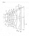
- FIG. 1 is a configuration diagram showing lens arrangement of an optical system in accordance with a first embodiment of the present invention
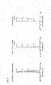
- FIG. 2 is an aberration diagram of the optical system shown in Table 1 and FIG. 1 ;
- FIG. 3 is a configuration diagram showing lens arrangement of an optical system in accordance with a second embodiment of the present invention.
- FIG. 4 is an aberration diagram of the optical system shown in Table 3 and FIG. 3 ;
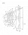
- FIG. 5 is a configuration diagram showing lens arrangement of an optical system in accordance with a third embodiment of the present invention.
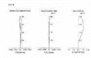
- FIG. 6 is an aberration diagram of the optical system shown in Table 5 and FIG. 5 .
- the thickness, size, and shape of lenses may be somewhat exaggerated for detailed description of the present invention.
- the shape of a spherical surface or an aspherical surface shown in the lens configuration diagram is shown as an example and not limited thereto.
- FIG. 1 is a lens configuration diagram showing an embodiment of an optical system in accordance with the present invention.
- a high resolution optical system of the present embodiment may include a first lens L1 having a positive refractive power, a second lens L2 having a negative refractive power, a third lens L3 having a positive refractive power, a fourth lens L4 having a negative refractive power, a fifth lens L5 having a positive refractive power, and a sixth lens L6 having a negative refractive power.
- the first lens L1 may have a shape in which an object-side surface is convex toward an object
- the second lens L2 may have a shape in which an upper surface is concave upward
- the fifth lens L5 may have a shape in which an upper surface is convex upward
- the sixth lens L6 may have a shape in which an upper surface is concave upward.
- an optical filter OF which consists of an infrared filter for blocking excessive infrared rays included in light passing through the optical system or a cover glass coated with the infrared filter, may be provided between the sixth lens L6 and an image surface 15.
- all of the first to sixth lenses L1 to L6 may be formed of plastic lenses, and one or both surfaces of the first to sixth lenses L1 to L6 may be formed as aspherical surfaces.
- the reason for forming at least one of the both surfaces of the first lens L1 and the second lens L2 of the lenses, which constitute the optical system in accordance with the present invention, as an aspherical surface is to improve a degree of freedom in design for facilitating correction of aberrations including chromatic aberration and mitigating manufacturing tolerances. Further, the reason for forming all of the first to sixth lens L1 to L6 with plastic lenses is to configure an optical system that can be used in mobile devices by achieving a light weight even though the optical system consists of a plurality of lenses due to characteristics of the optical system having easiness in manufacture of aspherical surfaces compared to glass lenses and mainly mounted to the mobile devices.
- the optical system of the present invention can perform aberration correction and achieve miniaturization while using a plurality of lenses by the following Conditional Expressions 1 and 4. Operational effects of Conditional Expressions will be described below. f ⁇ 4 / f ⁇ 2.5
- f4 represents a focal length of the fourth lens
- f represents a focal length of the entire optical system
- Conditional Expression 1 relates to conditions of optical power of the fourth lens and the entire optical system. It is possible to make the entire optical system compact by adjusting a refractive power of the fourth lens by Conditional Expression 1. At this time, when deviating from a lower limit of Conditional Expression 1, since it is difficult to secure performance of resolution of a peripheral portion of the lens due to an increase in negative power of the fourth lens, a length of the entire optical system may be increased to compensate for this. V ⁇ 1 - V ⁇ 4 ⁇ 40
- V1 represents an Abbe number of the first lens
- V4 represents an Abbe number of the fourth lens
- Conditional Expression 2 relates to conditions of correction of chromatic aberration of the optical system. When deviating from a lower limit of Conditional Expression 2, it may be impossible to implement high resolution of the entire optical system due to a difficulty in correction of chromatic aberration. 0.5 ⁇ OAL ⁇ f ⁇ 2.0
- OAL represents a distance from the vertex of an optical axis to an upper surface of the first lens
- f represents a focal length of the entire optical system.
- Conditional Expression 3 relates to conditions of the shape of lenses of the optical system. When deviating from a lower limit of Conditional Expression 3, since it is not possible to secure a proper field of view of the optical system, the field of view is reduced. When exceeding an upper limit, since the entire length of the optical system is increased, it is not possible to configure a compact optical system. V ⁇ 2 ⁇ 30
- V2 represents an Abbe number of the second lens.
- Conditional Expression 4 relates to conditions of chromatic aberration of the optical system. When deviating from a lower limit of Conditional Expression 4, it is impossible to implement high resolution of the entire optical system due to a difficulty in correction of chromatic aberration.
- first to third embodiments may include a first lens L1 having a positive refractive power and an object-side surface convex toward an object side; a second lens L2 having a negative refractive power and an upwardly concave upper surface; a third lens L3 having a positive refractive power; a fourth lens L4 having a negative refractive power; a fifth lens L5 having a positive refractive power and an upwardly convex upper surface; and a sixth lens L6 having a negative refractive power and an upwardly concave upper surface, and an optical filter OF, which consists of an infrared filter or a cover glass coated with the infrared filter, may be provided between the sixth lens L6 and an image surface 15.
- an optical filter OF which consists of an infrared filter or a cover glass coated with the infrared filter
- an aperture stop may be installed in the first lens L1 or between the first lens L1 and the second lens L2 to block unnecessary light incident on the optical system.
- first to sixth lenses L1 to L6 may be formed of plastic lenses, and one of both surfaces of the first to sixth lenses L1 to L6 may be formed as an aspherical surface.
- Equation 1 an aspherical surface used in each of the following embodiments is obtained from known Equation 1, and E and a number following the E used in a Conic constant K and aspherical coefficients A, B, C, D, E, and F represent a 10's power.
- E+02 represents 10 2
- E-02 represents 10 -2 .
- Z distance from vertex of lens in the direction of optical axis
- Table 1 shows numerical examples according to the first embodiment of the present invention.
- FIG. 1 is a configuration diagram showing lens arrangement of an optical system in accordance with the first embodiment of the present invention
- FIG. 2 shows an aberration diagram of the optical system shown in Table 1 and FIG. 1 .
- an effective focal length (F) of the entire optical system is 4.3mm
- a distance (OAL) from the vertex of an optical axis to an upper surface of the first lens is 5,449mm
- a field of view (FOV) is 67.7°.
- a focal length of the first lens L1 is 3.185mm
- a focal length of the second lens L2 is -5.089mm
- a focal length of the third lens is 19.79mm
- a focal length of the fourth lens L4 is -23.459mm
- a focal length of the fifth lens L5 is 2.067mm
- a focal length of the sixth lens L6 is -2.054mm.
- all of the first to sixth lenses L1 to L6 may be formed of plastic lenses.
- the * sign in front of the surface No. represents an aspherical surface.
- one or both surfaces of the first to sixth lenses L1 to L6 are aspherical surfaces.
- FIG. 3 is a configuration diagram showing lens arrangement of an optical system in accordance with the second embodiment of the present invention
- FIG. 4 shows an aberration diagram of the optical system shown in Table 3 and FIG. 3 .
- an effective focal length (F) of the entire optical system is 4.5mm
- a distance (OAL) from the vertex of an optical axis to an upper surface of the first lens is 5.592mm
- a field of view (FOV) is 65.3°.
- a focal length of the first lens L1 is 3.144mm
- a focal length of the second lens L2 is -4.836mm
- a focal length of the third lens L3 is 20.064mm
- a focal length of the fourth lens L4 is -48.537mm
- a focal length of the fifth lens L5 is 2.328mm
- a focal length of the sixth lens L6 is -2.157mm.
- all of the first to sixth lenses L1 to L6 may be formed of plastic lenses.
- the * sign in front of the surface No. represents an aspherical surface.
- one or both surfaces of the first to sixth lenses L1 to L6 are aspherical surfaces.
- FIG. 5 is a configuration diagram showing lens arrangement of an optical system in accordance with the third embodiment of the present invention
- FIG. 6 shows an aberration diagram of the optical system shown in Table 5 and FIG. 5 .
- an effective focal length (F) of the entire optical system is 4.37mm
- a distance (OAL) from the vertex of an optical axis to an upper surface of the first lens is 5.684mm
- a field of view (FOV) is 67.4°.
- a focal length of the first lens L1 is 3.089mm
- a focal length of the second lens L2 is -4.363mm
- a focal length of the third lens L3 is 9.937mm
- a focal length of the fourth lens L4 is -14.406mm
- a focal length of the fifth lens L5 is 2.136mm
- a focal length of the sixth lens L6 is -2.141 mm.
- all of the first to sixth lenses L1 to L6 may be formed of plastic lenses.
- the * sign in front of the surface No. represents an aspherical surface.
- one or both surfaces of the first to sixth lenses L1 to L6 are aspherical surfaces.
- the optical system in accordance with the present invention can achieve a light weight as well as reduce manufacturing costs by forming six lenses with plastic lenses.
- the present invention can implement high resolution by improving efficiency of correction of aberrations including chromatic aberration and minimizing chromatic aberrations.
- the present invention can improve a degree of freedom in design by forming both surfaces of six lenses, which constitute an optical system, as aspherical surfaces and manufacture a high resolution optical system by forming all of the first to sixth lenses with plastic lenses to reduce aberration values.
Landscapes
- Physics & Mathematics (AREA)
- General Physics & Mathematics (AREA)
- Optics & Photonics (AREA)
- Health & Medical Sciences (AREA)
- Toxicology (AREA)
- Lenses (AREA)
Abstract
Description
- Claim and incorporate by reference domestic priority application and foreign priority application as follows:
- This application claims the benefit under 35 U.S.C. Section 119 of Korean Patent Application Serial No.
10-2012-0118915 - The present invention relates to an optical system, and more particularly, to an optical system that can implement high resolution using six lenses.
- In general, mobile communication means such as mobile communication terminals, PDA, and smartphones become to have various additional functions in addition to basic communication functions along with their increased use and diversification of services provided through communication technology.
- In particular, camera modules mounted to the mobile communication means are in increasing demand as various convergence devices for high definition video shooting, automatic focus adjustment, and QR code recognition in addition to simple photo shooting using a single focus.
- Further, as the size of the camera modules is gradually reduced, higher resolution is required, and as the number of pixels of image sensors is gradually increased, high resolution optical systems are required.
- And, in recent times, manufacturing costs of the camera modules are gradually reduced along with price cuts of the mobile communication devices.
- In order to reduce the unit price of the camera module, first, it is most preferred to reduce manufacturing costs of lens groups constituting an optical system embedded in the camera module. However, in order to satisfy the above-mentioned conditions on improvement of resolution, the optical system should be constituted by applying a glass lens having high optical performance, but it is impossible to reduce the manufacturing costs of the camera module by using several sheets of expensive glass lenses.
- Further, when employing a plurality of glass lenses to overcome the resolution problem, it is impossible to reduce a weight of the optical system.
-
- [Patent Document]
- Patent Document 1: Korean Patent Laid-open Publication No.
2011-24872 - Therefore, the present invention has been invented in order to overcome the above-described disadvantages and problems raised in a conventional mobile camera optical system and it is, therefore, an object of the present invention to provide an optical system that can implement high resolution and reduce manufacturing costs by configuring an optical system using six aspherical plastic lenses.
- Further, it is another object of the present invention to provide a high resolution optical system that can implement high resolution and configure a compact optical system by properly placing optical power for six plastic lenses.
- In accordance with one aspect of the present invention to achieve the object, there is provided an optical system including, sequentially from an object side: a first lens having a positive refractive power and an object-side surface convex toward the object side; a second lens having a negative refractive power and an upwardly concave upper surface; a third lens having a positive refractive power; a fourth lens having a negative refractive power; a fifth lens having a positive refractive power and an upwardly convex upper surface; and a six lens having a negative refractive power and an upwardly concave upper surface.
- At this time, an aperture stop may be disposed in front of the first lens or between the first lens and the second lens to block unnecessary light of the light incident or passing through the optical system.
- Further, the optical system satisfies the following Conditional Expression with respect to conditions of optical power.
- [Conditional Expression] |f4 / f| > 2.5
- Here, f4 represents a focal length of the fourth lens, and f represents a focal length of the entire optical system.
- Further, the optical system satisfies the following Conditional Expression with respect to conditions of correction of chromatic aberration.
- [Conditional Expression] V1 - V4 < 40
- Here, V1 represents an Abbe number of the first lens, and V4 represents an Abbe number of the fourth lens.
- Further, the optical system satisfies the following Conditional Expression with respect to conditions of the shape of the fourth lens.
- [Conditional Expression] 0.5 < OAL / f < 2.0
- Here, OAL represents a distance from the vertex of an optical axis to an upper surface of the first lens, and f represents a focal length of the entire optical system.
- And, the optical system satisfies the following Conditional Expression with respect to conditions of chromatic aberration.
- [Conditional Expression] V2 < 30
- Here, V2 represents an Abbe number of the second lens.
- Further, the first to sixth lenses may be formed of plastic lenses, and at least one of both surfaces of the first to sixth lenses may be formed as an aspherical surface. Preferably, the both surfaces of the first to sixth lenses may be formed as aspherical surfaces.
- Further, an optical filter, which consists of a cover glass coated with an infrared cut filter for blocking excessive infrared rays included in light introduced from the outside, may be further included between the six lens and an image surface.
- These and/or other aspects and advantages of the present general inventive concept will become apparent and more readily appreciated from the following description of the embodiments, taken in conjunction with the accompanying drawings of which:
-
FIG. 1 is a configuration diagram showing lens arrangement of an optical system in accordance with a first embodiment of the present invention; -
FIG. 2 is an aberration diagram of the optical system shown in Table 1 andFIG. 1 ; -
FIG. 3 is a configuration diagram showing lens arrangement of an optical system in accordance with a second embodiment of the present invention; -
FIG. 4 is an aberration diagram of the optical system shown in Table 3 andFIG. 3 ; -
FIG. 5 is a configuration diagram showing lens arrangement of an optical system in accordance with a third embodiment of the present invention; and -
FIG. 6 is an aberration diagram of the optical system shown in Table 5 andFIG. 5 . - A matter regarding to an operation effect including a technical configuration for an object of an optical system in accordance with the present invention to achieve the object will be clearly appreciated through the following detailed description with reference to the accompanying drawings illustrating preferable embodiments of the present invention.
- However, in the following lens configuration diagram of each embodiment, the thickness, size, and shape of lenses may be somewhat exaggerated for detailed description of the present invention. Particularly, the shape of a spherical surface or an aspherical surface shown in the lens configuration diagram is shown as an example and not limited thereto.
- First,
FIG. 1 is a lens configuration diagram showing an embodiment of an optical system in accordance with the present invention. As shown, a high resolution optical system of the present embodiment may include a first lens L1 having a positive refractive power, a second lens L2 having a negative refractive power, a third lens L3 having a positive refractive power, a fourth lens L4 having a negative refractive power, a fifth lens L5 having a positive refractive power, and a sixth lens L6 having a negative refractive power. - At this time, as for the shape of the lenses constituting the optical system, the first lens L1 may have a shape in which an object-side surface is convex toward an object, the second lens L2 may have a shape in which an upper surface is concave upward, the fifth lens L5 may have a shape in which an upper surface is convex upward, and the sixth lens L6 may have a shape in which an upper surface is concave upward.
- Further, an optical filter OF, which consists of an infrared filter for blocking excessive infrared rays included in light passing through the optical system or a cover glass coated with the infrared filter, may be provided between the sixth lens L6 and an
image surface 15. - Further, in the optical system of the present invention, all of the first to sixth lenses L1 to L6 may be formed of plastic lenses, and one or both surfaces of the first to sixth lenses L1 to L6 may be formed as aspherical surfaces.
- The reason for forming at least one of the both surfaces of the first lens L1 and the second lens L2 of the lenses, which constitute the optical system in accordance with the present invention, as an aspherical surface is to improve a degree of freedom in design for facilitating correction of aberrations including chromatic aberration and mitigating manufacturing tolerances. Further, the reason for forming all of the first to sixth lens L1 to L6 with plastic lenses is to configure an optical system that can be used in mobile devices by achieving a light weight even though the optical system consists of a plurality of lenses due to characteristics of the optical system having easiness in manufacture of aspherical surfaces compared to glass lenses and mainly mounted to the mobile devices.
- Meanwhile, as mentioned above, the optical system of the present invention can perform aberration correction and achieve miniaturization while using a plurality of lenses by the following
Conditional Expressions 1 and 4. Operational effects of Conditional Expressions will be described below.
- Here, f4 represents a focal length of the fourth lens, and f represents a focal length of the entire optical system.
- Conditional Expression 1 relates to conditions of optical power of the fourth lens and the entire optical system. It is possible to make the entire optical system compact by adjusting a refractive power of the fourth lens by Conditional Expression 1. At this time, when deviating from a lower limit of Conditional Expression 1, since it is difficult to secure performance of resolution of a peripheral portion of the lens due to an increase in negative power of the fourth lens, a length of the entire optical system may be increased to compensate for this.

- Here, V1 represents an Abbe number of the first lens, and V4 represents an Abbe number of the fourth lens.
-
Conditional Expression 2 relates to conditions of correction of chromatic aberration of the optical system. When deviating from a lower limit ofConditional Expression 2, it may be impossible to implement high resolution of the entire optical system due to a difficulty in correction of chromatic aberration.
- Here, OAL represents a distance from the vertex of an optical axis to an upper surface of the first lens, and f represents a focal length of the entire optical system.
-
Conditional Expression 3 relates to conditions of the shape of lenses of the optical system. When deviating from a lower limit ofConditional Expression 3, since it is not possible to secure a proper field of view of the optical system, the field of view is reduced. When exceeding an upper limit, since the entire length of the optical system is increased, it is not possible to configure a compact optical system.
- Here, V2 represents an Abbe number of the second lens.
-
Conditional Expression 4 relates to conditions of chromatic aberration of the optical system. When deviating from a lower limit ofConditional Expression 4, it is impossible to implement high resolution of the entire optical system due to a difficulty in correction of chromatic aberration. - Hereinafter, a compact wide-angle optical system in accordance with the present invention will be described in detail with reference to specific numerical embodiments.
- As described above, all of the following first to third embodiments may include a first lens L1 having a positive refractive power and an object-side surface convex toward an object side; a second lens L2 having a negative refractive power and an upwardly concave upper surface; a third lens L3 having a positive refractive power; a fourth lens L4 having a negative refractive power; a fifth lens L5 having a positive refractive power and an upwardly convex upper surface; and a sixth lens L6 having a negative refractive power and an upwardly concave upper surface, and an optical filter OF, which consists of an infrared filter or a cover glass coated with the infrared filter, may be provided between the sixth lens L6 and an
image surface 15. - Further, an aperture stop (AS) may be installed in the first lens L1 or between the first lens L1 and the second lens L2 to block unnecessary light incident on the optical system.
- Further, the first to sixth lenses L1 to L6 may be formed of plastic lenses, and one of both surfaces of the first to sixth lenses L1 to L6 may be formed as an aspherical surface.
- Meanwhile, an aspherical surface used in each of the following embodiments is obtained from known Equation 1, and E and a number following the E used in a Conic constant K and aspherical coefficients A, B, C, D, E, and F represent a 10's power. For example, E+02 represents 102, and E-02 represents 10-2.
- [Equation 1]

- Here, Z : distance from vertex of lens in the direction of optical axis
- Y : distance in the direction perpendicular to optical axis
- c: reciprocal of radius of curvature (r) at vertex of lens
- K : Conic constant
- A, B, C, D, E, F : aspherical coefficients
- [First embodiment]
- The following Table 1 shows numerical examples according to the first embodiment of the present invention.
- Further,
FIG. 1 is a configuration diagram showing lens arrangement of an optical system in accordance with the first embodiment of the present invention, andFIG. 2 shows an aberration diagram of the optical system shown in Table 1 andFIG. 1 . - In the first embodiment, an effective focal length (F) of the entire optical system is 4.3mm, a distance (OAL) from the vertex of an optical axis to an upper surface of the first lens is 5,449mm, and a field of view (FOV) is 67.7°.
- Further, a focal length of the first lens L1 is 3.185mm, a focal length of the second lens L2 is -5.089mm, a focal length of the third lens is 19.79mm, a focal length of the fourth lens L4 is -23.459mm, a focal length of the fifth lens L5 is 2.067mm, and a focal length of the sixth lens L6 is -2.054mm.
- At this time, all of the first to sixth lenses L1 to L6 may be formed of plastic lenses.
- [Table 1]
Surface No. Radius of Curvature (R) Thickness (mm) Refractive Index (n) Abbe Number (v) Remarks *1 1.794 0.62 1.544 56.1 First lens *2 -51.128 0.13 *3 4.935 0.30 1.632 23.4 Second lens *4 1.914 0.37 *5 16.281 0.30 1.544 56.1 Third lens *6 -32.007 0.15 *7 -8.518 0.30 1.632 23.4 Fourth lens *8 -20.000 0.27 *9 -3.451 0.87 1.544 56.1 Fifth lens *10 -0.927 0.10 *11 14.414 0.56 1.544 56.1 Sixth lens *12 1.027 0.32 13 ∞ 0.30 1.517 64.2 Optical filter 14 ∞ 0.85 - In Table 1, the * sign in front of the surface No. represents an aspherical surface. In the first embodiment, one or both surfaces of the first to sixth lenses L1 to L6 are aspherical surfaces.
- Further, values of aspherical coefficients of the first embodiment by Equation 1 are as in the following Table 2.
- [Table 2]
Surface No. K A B C D E 1 0 0.00080 -0.00550 0.01344 -0.01904 0 2 0 -0.06313 0.13673 0.15630 0.04743 0 3 0 -0.18849 0.33976 -0.35757 0.05301 -0.00906 4 0 -0.17307 0.28346 -0.24419 0.95736 0 5 0 -0.09130 0.03735 -0.00227 -0.01159 0 6 0 0.03190 0.03715 -0.02333 0.00066 0 7 0 -0.01121 0.00585 -0.00030 -0.00260 0 8 0 -0.02243 0.00251 -0.00028 0.00110 0 9 -14.81500 -0.05738 0.04788 -0.03246 0.01215 -0.00181 10 -3.85011 -0.08732 0.06137 -0.03202 0.01081 -1.44E-03 11 0 -0.03276 -0.00422 -0.00374 -0.00065 3.65E-03 12 -6.73354 -0.04177 0.00844 -0.00187 0.00022 -1.13E-05 - [Second Embodiment]
- The following Table 3 shows numerical examples according to the second embodiment of the present invention.
- Further,
FIG. 3 is a configuration diagram showing lens arrangement of an optical system in accordance with the second embodiment of the present invention, andFIG. 4 shows an aberration diagram of the optical system shown in Table 3 andFIG. 3 . - In the second embodiment, an effective focal length (F) of the entire optical system is 4.5mm, a distance (OAL) from the vertex of an optical axis to an upper surface of the first lens is 5.592mm, and a field of view (FOV) is 65.3°.
- Further, a focal length of the first lens L1 is 3.144mm, a focal length of the second lens L2 is -4.836mm, a focal length of the third lens L3 is 20.064mm, a focal length of the fourth lens L4 is -48.537mm, a focal length of the fifth lens L5 is 2.328mm, and a focal length of the sixth lens L6 is -2.157mm.
- At this time, all of the first to sixth lenses L1 to L6 may be formed of plastic lenses.
- [Table 3]
Surface No. Radius of Curvature (R) Thickness (mm) Refractive Index (n) Abbe Number Remarks *1 1.839 0.68 1.544 56.1 First lens *2 -22.721 0.12 *3 5.344 0.30 1.632 23.4 Second lens *4 1.915 0.33 *5 -24.900 0.31 1.544 56.1 Third lens *6 -7.647 0.18 *7 -12.088 0.30 1.632 23.4 Fourth lens *8 -20.000 0.37 *9 -3.264 0.81 1.544 56.1 Fifth lens *10 -0.995 0.11 *11 -304.909 0.62 1.544 56.1 Sixth lens *12 1.184 0.29 13 ∞ 0.30 1.517 64.2 Optical filter 14 ∞ 0.85 - In Table 3, the * sign in front of the surface No. represents an aspherical surface. In the second embodiment, one or both surfaces of the first to sixth lenses L1 to L6 are aspherical surfaces.
- Further, values of aspherical coefficients of the second embodiment by Equation 1 are as in the following Table 4.
- [Table 4]
Surface No. K A B C D E 1 0 0.00141 -0.00889 0.01567 -0.01664 0 2 0 -0.05635 0.13584 0.15710 0.04960 0 3 0 -0.18277 0.34510 -0.35977 0.14880 -0.00883 4 0 -0.17854 0.28954 -0.24213 0.09009 0 5 0 -0.09326 0.04705 -0.00190 -0.01416 0 6 0 -0.03383 0.03559 -0.02350 0.00068 0 7 0 -0.01421 0.00209 -0.00056 -0.00134 0 8 0 -0.02287 0.00331 -0.00045 0.00087 0 9 -12.78900 -0.06441 0.04598 -0.03273 0.01200 -0.00192 10 -3.78835 -0.08652 0.06057 -0.03270 0.01074 -1.38E-03 11 0 -0.03082 -0.00353 0.00377 -0.00065 3.54E-05 12 -733606 -0.04270 0.00911 -0.00192 0.00022 -1.03E-05 - [Third Embodiment]
- The following Table 5 shows numerical examples according to the third embodiment of the present invention.
- Further,
FIG. 5 is a configuration diagram showing lens arrangement of an optical system in accordance with the third embodiment of the present invention, andFIG. 6 shows an aberration diagram of the optical system shown in Table 5 andFIG. 5 . - In the third embodiment, an effective focal length (F) of the entire optical system is 4.37mm, a distance (OAL) from the vertex of an optical axis to an upper surface of the first lens is 5.684mm, and a field of view (FOV) is 67.4°.
- Further, a focal length of the first lens L1 is 3.089mm, a focal length of the second lens L2 is -4.363mm, a focal length of the third lens L3 is 9.937mm, a focal length of the fourth lens L4 is -14.406mm, a focal length of the fifth lens L5 is 2.136mm, and a focal length of the sixth lens L6 is -2.141 mm.
- At this time, all of the first to sixth lenses L1 to L6 may be formed of plastic lenses.
- [Table 5]
Surface No. Radius of Curvature (R) Thickness (mm) Refractive Index (n) Abbe Number (v) Remarks *1 1.945 0.71 1.544 56.1 First lens *2 -11.133 0.11 *3 5.393 0.31 1.632 23.4 Second lens *4 1.796 0.35 *5 -192.752 0.39 1.544 56.1 Third lens *6 -5.285 0.12 *7 -5.196 0.32 1.544 56.1 Fourth lens *8 -15.612 0.32 *9 -2.895 0.87 1.544 56.1 Fifth lens *10 -0.920 0.10 *11 8.644 0.57 1.544 56.1 Sixth lens *12 1.007 0.36 13 ∞ 0.30 1.517 64.2 Optical filter 14 ∞ 0.85 - In Table 5, the * sign in front of the surface No. represents an aspherical surface. In the third embodiment, one or both surfaces of the first to sixth lenses L1 to L6 are aspherical surfaces.
- Further, values of aspherical coefficients of the third embodiment by Equation 1 are as in the following Table 6.
- [Table 6]
Surface No. K A B C D E 1 0 0.00051 -0.01481 0.01850 -0.01714 0 2 0 -0.04903 0.13616 0.16040 0.05199 0 3 0 -0.17566 0.35084 -0.35797 0.14694 -0.00923 4 0 -0.19005 0.29351 -0.24124 0.08676 0 5 0 -0.09684 0.04540 -0.00410 -0.01300 0 6 0 -0.03318 0.04118 -0.02075 0.00143 0 7 0 -0.01820 0.00061 0.00218 -0.00123 0 8 0 -0.02483 0.00321 -0.00131 1.54E-05 0 9 -7.32031 -0.04726 0.05039 -0.03290 0.01176 -0.00212 10 -3.64537 -0.09621 0.06332 -0.03262 0.010732 -1.33E-03 11 0 -0.04093 -0.00257 0.00387 -0.00065 3.33E-05 12 -6.13717 -0.04287 0.00920 -0.00184 0.00022 -1.14E-05 - Meanwhile, values of Conditional Expressions for the first to third embodiments are as in the following Table 7.
- [Table 7]
Classification Embodiment 1 Embodiment 2Embodiment 3f4/f -5.455581 -10.786 -3.296568 v1-v4 32.7 32.7 0 OAL/f 1.2671427 1.2425765 1.3006439 v2 23.4 23.4 23.4 - As described above, the optical system in accordance with the present invention can achieve a light weight as well as reduce manufacturing costs by forming six lenses with plastic lenses.
- Further, the present invention can implement high resolution by improving efficiency of correction of aberrations including chromatic aberration and minimizing chromatic aberrations.
- Further, the present invention can improve a degree of freedom in design by forming both surfaces of six lenses, which constitute an optical system, as aspherical surfaces and manufacture a high resolution optical system by forming all of the first to sixth lenses with plastic lenses to reduce aberration values.
- As described above, although the preferable embodiments of the present invention have been shown and described, it will be appreciated by those skilled in the art that substitutions, modifications and variations may be made in these embodiments without departing from the principles and spirit of the general inventive concept, the scope of which is defined in the appended claims and their equivalents.
Claims (9)
- A high resolution optical system comprising, sequentially from an object side:a first lens having a positive refractive power and an object-side surface convex toward the object side;a second lens having a negative refractive power and an upwardly concave upper surface;a third lens having a positive refractive power;a fourth lens having a negative refractive power;a fifth lens having a positive refractive power and an upwardly convex upper surface; anda six lens having a negative refractive power and an upwardly concave upper surface.
- The high resolution optical system according to claim 1, wherein an aperture stop is disposed in front of the first lens or between the first lens and the second lens.
- The high resolution optical system according to claim 1, wherein the optical system satisfies the following Conditional Expression with respect to conditions of optical power:

here, f4 represents a focal length of the fourth lens, and
f represents a focal length of the entire optical system. - The high resolution optical system according to claim 1, wherein the optical system satisfies the following Conditional Expression with respect to conditions of correction of chromatic aberration:

here, V1 represents an Abbe number of the first lens, and
V4 represents an Abbe number of the fourth lens. - The high resolution optical system according to claim 1, wherein the optical system satisfies the following Conditional Expression with respect to conditions of the shape of the fourth lens:

here, OAL represents a distance from the vertex of an optical axis to an upper surface of the first lens, and
f represents a focal length of the entire optical system. - The high resolution optical system according to claim 1, wherein the optical system satisfies the following Conditional Expression with respect to conditions of chromatic aberration:

here, V2 represents an Abbe number of the second lens. - The high resolution optical system according to claim 1, wherein the first to sixth lenses are formed of plastic lenses.
- The high resolution optical system according to claim 7, wherein at least one or both surfaces of the first to sixth lenses are formed as aspherical surfaces.
- The high resolution optical system according to claim 1, further comprising:an optical filter consisting of a cover glass coated with an infrared cut filter for blocking excessive infrared rays included in light introduced from the outside between the six lens and an image surface.
Applications Claiming Priority (1)
| Application Number | Priority Date | Filing Date | Title |
|---|---|---|---|
| KR1020120118915A KR101452045B1 (en) | 2012-10-25 | 2012-10-25 | Optical System |
Publications (1)
| Publication Number | Publication Date |
|---|---|
| EP2725403A1 true EP2725403A1 (en) | 2014-04-30 |
Family
ID=48745856
Family Applications (1)
| Application Number | Title | Priority Date | Filing Date |
|---|---|---|---|
| EP13275155.3A Withdrawn EP2725403A1 (en) | 2012-10-25 | 2013-07-03 | High resolution optical system |
Country Status (6)
| Country | Link |
|---|---|
| US (5) | US9952357B2 (en) |
| EP (1) | EP2725403A1 (en) |
| JP (2) | JP5744977B2 (en) |
| KR (1) | KR101452045B1 (en) |
| CN (2) | CN107037571A (en) |
| TW (1) | TWI491912B (en) |
Cited By (5)
| Publication number | Priority date | Publication date | Assignee | Title |
|---|---|---|---|---|
| KR20170136486A (en) * | 2015-11-26 | 2017-12-11 | 삼성전기주식회사 | Optical Imaging System |
| KR20170137022A (en) * | 2015-11-24 | 2017-12-12 | 삼성전기주식회사 | Optical Imaging System |
| JP2019152774A (en) * | 2018-03-05 | 2019-09-12 | カンタツ株式会社 | Image capturing lens |
| TWI709785B (en) * | 2019-08-06 | 2020-11-11 | 大陸商玉晶光電(廈門)有限公司 | Optical imaging lens |
| KR20210109495A (en) * | 2017-12-04 | 2021-09-06 | 삼성전기주식회사 | Optical Imaging System |
Families Citing this family (39)
| Publication number | Priority date | Publication date | Assignee | Title |
|---|---|---|---|---|
| KR101452045B1 (en) | 2012-10-25 | 2014-10-21 | 삼성전기주식회사 | Optical System |
| JP6300183B2 (en) * | 2013-04-22 | 2018-03-28 | コニカミノルタ株式会社 | Imaging lens, imaging device, and portable terminal |
| TWI463169B (en) | 2013-07-25 | 2014-12-01 | Largan Precision Co Ltd | Image lens assembly and image capturing device |
| TWI477808B (en) * | 2014-01-17 | 2015-03-21 | Largan Precision Co Ltd | Photographic optical lens, image capturing device, and vehicle imaging device |
| TWI484213B (en) * | 2014-05-23 | 2015-05-11 | 玉晶光電股份有限公司 | Optical imaging lens and electronic device using the same |
| CN104238073B (en) * | 2014-05-23 | 2017-01-18 | 玉晶光电(厦门)有限公司 | Optical imaging lens and electronic device using the lens |
| TWI484214B (en) * | 2014-06-17 | 2015-05-11 | 玉晶光電股份有限公司 | Portable electronic device and optical imaging lens thereof |
| TWI500961B (en) * | 2014-07-04 | 2015-09-21 | Largan Precision Co Ltd | Optical imaging lens assembly, image capturing unit and electronic device |
| TWI500960B (en) * | 2014-07-04 | 2015-09-21 | Largan Precision Co Ltd | Photographing optical lens system, image capturing unit and mobile terminal |
| CN104330875B (en) | 2014-07-07 | 2017-11-10 | 玉晶光电(厦门)有限公司 | Portable electronic devices and its optical imaging lens |
| CN104330876B (en) * | 2014-07-07 | 2017-03-08 | 玉晶光电(厦门)有限公司 | Optical imaging lens and the electronic installation applying this optical imaging lens |
| CN105242374B (en) * | 2014-07-11 | 2018-01-12 | 佳能企业股份有限公司 | optical lens |
| CN104330869B (en) | 2014-07-29 | 2016-08-24 | 玉晶光电(厦门)有限公司 | Optical imaging lens and apply the electronic installation of this camera lens |
| CN105334595B (en) * | 2014-08-06 | 2017-12-01 | 玉晶光电(厦门)有限公司 | Portable electronic devices and its optical imaging lens |
| KR101670130B1 (en) * | 2014-09-22 | 2016-10-27 | 삼성전기주식회사 | Lens module |
| KR101882990B1 (en) * | 2015-03-11 | 2018-07-30 | 에이에이씨 어쿠스틱 테크놀로지스(심천)컴퍼니 리미티드 | Imaging Lens System |
| KR101820952B1 (en) | 2015-03-11 | 2018-03-09 | 에이에이씨 어쿠스틱 테크놀로지스(심천)컴퍼니 리미티드 | Imaging Lens System |
| CN104991329B (en) * | 2015-05-22 | 2017-08-25 | 福建浩蓝光电有限公司 | A kind of high-resolution projection lens for industry 3D scanning systems |
| TWI548895B (en) * | 2015-07-03 | 2016-09-11 | 大立光電股份有限公司 | Image capturing lens system, image capturing apparatus and electronic device |
| CN105487201B (en) * | 2015-12-14 | 2018-03-20 | 浙江舜宇光学有限公司 | Ultra-thin camera lens |
| JP5895095B1 (en) * | 2015-12-21 | 2016-03-30 | エーエーシー テクノロジーズ ピーティーイー リミテッドAac Technologies Pte.Ltd. | Imaging lens |
| CN105403981B (en) * | 2015-12-22 | 2018-02-13 | 中山联合光电科技股份有限公司 | A kind of high image quality optical lens |
| KR101834554B1 (en) * | 2016-03-18 | 2018-04-19 | 주식회사 에이스솔루텍 | Photographic lens optical system |
| TWI617831B (en) * | 2016-05-20 | 2018-03-11 | 大立光電股份有限公司 | Optical imaging lens, image capturing apparatus and electronic device |
| CN106526796B (en) * | 2016-08-05 | 2019-09-24 | 玉晶光电(厦门)有限公司 | Optical mirror slip group |
| KR101946261B1 (en) * | 2016-12-28 | 2019-02-11 | 삼성전기 주식회사 | Optical system |
| CN115016106B (en) | 2017-05-03 | 2024-08-13 | 信泰光学(深圳)有限公司 | Imaging Lenses |
| TWI743117B (en) * | 2017-05-03 | 2021-10-21 | 大陸商信泰光學(深圳)有限公司 | Lens assembly |
| CN107450157B (en) * | 2017-06-02 | 2020-01-10 | 玉晶光电(厦门)有限公司 | Optical imaging lens |
| KR101946262B1 (en) | 2017-10-23 | 2019-02-11 | 삼성전기 주식회사 | Optical Imaging System |
| CN109581627B (en) * | 2018-12-31 | 2021-07-09 | 常州市瑞泰光电有限公司 | Camera optics |
| CN110346912B (en) * | 2019-06-30 | 2021-11-02 | 瑞声光学解决方案私人有限公司 | Image pickup optical lens |
| CN110412740B (en) * | 2019-06-30 | 2021-11-02 | 瑞声光学解决方案私人有限公司 | Image pickup optical lens |
| CN119676548A (en) | 2019-07-11 | 2025-03-21 | 华为技术有限公司 | Lens, camera and electronic device |
| CN110658612A (en) * | 2019-11-13 | 2020-01-07 | 玉晶光电(厦门)有限公司 | Optical imaging lens |
| KR102149983B1 (en) * | 2020-01-16 | 2020-08-31 | 주식회사 디오스텍 | Mobile camera lens system for ultra-high density pixel |
| US12517323B2 (en) | 2020-02-10 | 2026-01-06 | Samsung Electro-Mechanics Co., Ltd. | Optical imaging system |
| CN111830690B (en) * | 2020-09-19 | 2020-11-27 | 瑞泰光学(常州)有限公司 | Image pickup optical lens |
| KR102526441B1 (en) * | 2020-10-12 | 2023-04-27 | 삼성전기주식회사 | Optical Imaging System |
Citations (4)
| Publication number | Priority date | Publication date | Assignee | Title |
|---|---|---|---|---|
| WO2012008357A1 (en) * | 2010-07-16 | 2012-01-19 | コニカミノルタオプト株式会社 | Image capture lens |
| CN202217102U (en) * | 2011-06-28 | 2012-05-09 | 大立光电股份有限公司 | Optical image capturing lens assembly |
| TW201226964A (en) * | 2012-03-09 | 2012-07-01 | Largan Precision Co Ltd | Optical image system |
| CN202330846U (en) * | 2011-08-05 | 2012-07-11 | 大立光电股份有限公司 | Image capturing optical lens assembly |
Family Cites Families (18)
| Publication number | Priority date | Publication date | Assignee | Title |
|---|---|---|---|---|
| JP3441958B2 (en) | 1998-03-03 | 2003-09-02 | 富士写真光機株式会社 | 3-group zoom lens |
| US6279622B1 (en) | 2000-02-07 | 2001-08-28 | Ethicon, Inc. | Method and system for delivering and metering liquid sterilant |
| JP2002062475A (en) * | 2000-08-17 | 2002-02-28 | Nikon Corp | Computer-readable recording medium storing a program for designing an optical system and optical system design system |
| KR101499969B1 (en) | 2008-10-10 | 2015-03-18 | 엘지이노텍 주식회사 | Imaging Lens and Camera Moudule including the same |
| US20100277576A1 (en) * | 2009-04-29 | 2010-11-04 | David Fattal | Systems for Capturing Images Through a Display |
| KR101626551B1 (en) * | 2009-09-03 | 2016-06-01 | 엘지이노텍 주식회사 | Lens module |
| KR101108802B1 (en) * | 2009-12-08 | 2012-02-09 | 삼성전기주식회사 | Optical system for camera |
| JP2012155223A (en) * | 2011-01-27 | 2012-08-16 | Tamron Co Ltd | Wide-angle single-focus lens |
| CN102621664B (en) | 2011-01-27 | 2014-05-21 | 大立光电股份有限公司 | Image capturing lens assembly |
| TWI435138B (en) * | 2011-06-20 | 2014-04-21 | Largan Precision Co | Optical imaging system for pickup |
| TWI438471B (en) * | 2011-08-24 | 2014-05-21 | Largan Precision Co Ltd | Optical image capturing lenses |
| TWI438475B (en) * | 2011-09-15 | 2014-05-21 | Largan Precision Co Ltd | Optical image capturing lens assembly |
| JPWO2013114812A1 (en) * | 2012-01-30 | 2015-05-11 | 富士フイルム株式会社 | Imaging lens and imaging device provided with imaging lens |
| TWI472826B (en) * | 2012-06-06 | 2015-02-11 | Largan Precision Co Ltd | Optical image lens system |
| JP6047700B2 (en) * | 2012-06-21 | 2016-12-21 | 株式会社オプトロジック | Imaging lens |
| JP5854227B2 (en) * | 2012-08-28 | 2016-02-09 | ソニー株式会社 | Imaging lens and imaging apparatus |
| TWI438521B (en) * | 2012-10-02 | 2014-05-21 | Largan Precision Co Ltd | Image system lens assembly |
| KR101452045B1 (en) | 2012-10-25 | 2014-10-21 | 삼성전기주식회사 | Optical System |
-
2012
- 2012-10-25 KR KR1020120118915A patent/KR101452045B1/en active Active
-
2013
- 2013-07-03 EP EP13275155.3A patent/EP2725403A1/en not_active Withdrawn
- 2013-07-16 JP JP2013147734A patent/JP5744977B2/en active Active
- 2013-07-17 TW TW102125546A patent/TWI491912B/en active
- 2013-07-18 CN CN201710474360.9A patent/CN107037571A/en active Pending
- 2013-07-18 CN CN201310303653.2A patent/CN103777311B/en active Active
- 2013-07-30 US US13/954,938 patent/US9952357B2/en active Active
-
2015
- 2015-03-16 JP JP2015051952A patent/JP2015111310A/en active Pending
-
2018
- 2018-02-01 US US15/885,990 patent/US10605964B2/en active Active
-
2020
- 2020-02-20 US US16/795,920 patent/US11300715B2/en active Active
-
2022
- 2022-03-04 US US17/687,145 patent/US11899183B2/en active Active
-
2023
- 2023-12-28 US US18/398,913 patent/US12566318B2/en active Active
Patent Citations (8)
| Publication number | Priority date | Publication date | Assignee | Title |
|---|---|---|---|---|
| WO2012008357A1 (en) * | 2010-07-16 | 2012-01-19 | コニカミノルタオプト株式会社 | Image capture lens |
| US20130120858A1 (en) * | 2010-07-16 | 2013-05-16 | Eigo Sano | Image Capture Lens |
| CN202217102U (en) * | 2011-06-28 | 2012-05-09 | 大立光电股份有限公司 | Optical image capturing lens assembly |
| US20130003193A1 (en) * | 2011-06-28 | 2013-01-03 | Largan Precision Co., Ltd. | Optical image capturing lens assembly |
| CN202330846U (en) * | 2011-08-05 | 2012-07-11 | 大立光电股份有限公司 | Image capturing optical lens assembly |
| US20130033762A1 (en) * | 2011-08-05 | 2013-02-07 | Largan Precision Co. Ltd. | Photographing optical lens assembly |
| TW201226964A (en) * | 2012-03-09 | 2012-07-01 | Largan Precision Co Ltd | Optical image system |
| US20130235473A1 (en) * | 2012-03-09 | 2013-09-12 | Largan Precision Co., Ltd. | Optical image system |
Non-Patent Citations (1)
| Title |
|---|
| "Handbook of optical systems, Aberration theory and correction of optical systems", 1 January 2007, WILEY-VCH, Weinheim, DE, ISBN: 978-3-527-40379-0, article HERBERT GROSS ET AL: "Handbook of Optical Systems, Vol.3: Aberration Theory and Correction of Optical Systems", pages: 377 - 379, XP055258161 * |
Cited By (5)
| Publication number | Priority date | Publication date | Assignee | Title |
|---|---|---|---|---|
| KR20170137022A (en) * | 2015-11-24 | 2017-12-12 | 삼성전기주식회사 | Optical Imaging System |
| KR20170136486A (en) * | 2015-11-26 | 2017-12-11 | 삼성전기주식회사 | Optical Imaging System |
| KR20210109495A (en) * | 2017-12-04 | 2021-09-06 | 삼성전기주식회사 | Optical Imaging System |
| JP2019152774A (en) * | 2018-03-05 | 2019-09-12 | カンタツ株式会社 | Image capturing lens |
| TWI709785B (en) * | 2019-08-06 | 2020-11-11 | 大陸商玉晶光電(廈門)有限公司 | Optical imaging lens |
Also Published As
| Publication number | Publication date |
|---|---|
| US20240134162A1 (en) | 2024-04-25 |
| US20140118817A1 (en) | 2014-05-01 |
| US20180156946A1 (en) | 2018-06-07 |
| KR101452045B1 (en) | 2014-10-21 |
| US20220187506A1 (en) | 2022-06-16 |
| US20240231051A9 (en) | 2024-07-11 |
| US9952357B2 (en) | 2018-04-24 |
| JP2015111310A (en) | 2015-06-18 |
| US11300715B2 (en) | 2022-04-12 |
| US11899183B2 (en) | 2024-02-13 |
| CN103777311B (en) | 2017-06-30 |
| US12566318B2 (en) | 2026-03-03 |
| JP2014085665A (en) | 2014-05-12 |
| US20200192005A1 (en) | 2020-06-18 |
| KR20140067182A (en) | 2014-06-05 |
| CN103777311A (en) | 2014-05-07 |
| TW201416702A (en) | 2014-05-01 |
| TWI491912B (en) | 2015-07-11 |
| US10605964B2 (en) | 2020-03-31 |
| JP5744977B2 (en) | 2015-07-08 |
| CN107037571A (en) | 2017-08-11 |
Similar Documents
| Publication | Publication Date | Title |
|---|---|---|
| US20220187506A1 (en) | High resolution optical system | |
| US9348112B2 (en) | Optical system | |
| US9429736B2 (en) | Optical system | |
| EP2860564B1 (en) | Lens module | |
| CN108519658B (en) | Lens module | |
| CN110687662B (en) | Lens module | |
| EP2840427A1 (en) | Lens module | |
| KR102254879B1 (en) | Optical System | |
| KR102015852B1 (en) | Imaging lens | |
| CN110221404B (en) | Optical system | |
| KR101901692B1 (en) | Optical System | |
| EP2685302A1 (en) | Small-size and wide field-of-view optical system | |
| CN113075783B (en) | Optical systems, lens modules and terminal equipment | |
| KR101681382B1 (en) | Optical System | |
| KR101431980B1 (en) | Optical System |
Legal Events
| Date | Code | Title | Description |
|---|---|---|---|
| PUAI | Public reference made under article 153(3) epc to a published international application that has entered the european phase |
Free format text: ORIGINAL CODE: 0009012 |
|
| 17P | Request for examination filed |
Effective date: 20130703 |
|
| AK | Designated contracting states |
Kind code of ref document: A1 Designated state(s): AL AT BE BG CH CY CZ DE DK EE ES FI FR GB GR HR HU IE IS IT LI LT LU LV MC MK MT NL NO PL PT RO RS SE SI SK SM TR |
|
| AX | Request for extension of the european patent |
Extension state: BA ME |
|
| STAA | Information on the status of an ep patent application or granted ep patent |
Free format text: STATUS: EXAMINATION IS IN PROGRESS |
|
| 17Q | First examination report despatched |
Effective date: 20180718 |
|
| STAA | Information on the status of an ep patent application or granted ep patent |
Free format text: STATUS: THE APPLICATION IS DEEMED TO BE WITHDRAWN |
|
| 18D | Application deemed to be withdrawn |
Effective date: 20230503 |