EP2725286A1 - Leuchte mit LED-Lichtquelle - Google Patents
Leuchte mit LED-Lichtquelle Download PDFInfo
- Publication number
- EP2725286A1 EP2725286A1 EP13190472.4A EP13190472A EP2725286A1 EP 2725286 A1 EP2725286 A1 EP 2725286A1 EP 13190472 A EP13190472 A EP 13190472A EP 2725286 A1 EP2725286 A1 EP 2725286A1
- Authority
- EP
- European Patent Office
- Prior art keywords
- light
- plate
- reflection
- luminaire according
- glare
- Prior art date
- Legal status (The legal status is an assumption and is not a legal conclusion. Google has not performed a legal analysis and makes no representation as to the accuracy of the status listed.)
- Granted
Links
Images

Classifications
-
- F—MECHANICAL ENGINEERING; LIGHTING; HEATING; WEAPONS; BLASTING
- F21—LIGHTING
- F21S—NON-PORTABLE LIGHTING DEVICES; SYSTEMS THEREOF; VEHICLE LIGHTING DEVICES SPECIALLY ADAPTED FOR VEHICLE EXTERIORS
- F21S6/00—Lighting devices intended to be free-standing
- F21S6/002—Table lamps, e.g. for ambient lighting
- F21S6/003—Table lamps, e.g. for ambient lighting for task lighting, e.g. for reading or desk work, e.g. angle poise lamps
-
- F—MECHANICAL ENGINEERING; LIGHTING; HEATING; WEAPONS; BLASTING
- F21—LIGHTING
- F21V—FUNCTIONAL FEATURES OR DETAILS OF LIGHTING DEVICES OR SYSTEMS THEREOF; STRUCTURAL COMBINATIONS OF LIGHTING DEVICES WITH OTHER ARTICLES, NOT OTHERWISE PROVIDED FOR
- F21V7/00—Reflectors for light sources
- F21V7/0008—Reflectors for light sources providing for indirect lighting
-
- F—MECHANICAL ENGINEERING; LIGHTING; HEATING; WEAPONS; BLASTING
- F21—LIGHTING
- F21V—FUNCTIONAL FEATURES OR DETAILS OF LIGHTING DEVICES OR SYSTEMS THEREOF; STRUCTURAL COMBINATIONS OF LIGHTING DEVICES WITH OTHER ARTICLES, NOT OTHERWISE PROVIDED FOR
- F21V7/00—Reflectors for light sources
- F21V7/22—Reflectors for light sources characterised by materials, surface treatments or coatings, e.g. dichroic reflectors
- F21V7/24—Reflectors for light sources characterised by materials, surface treatments or coatings, e.g. dichroic reflectors characterised by the material
-
- F—MECHANICAL ENGINEERING; LIGHTING; HEATING; WEAPONS; BLASTING
- F21—LIGHTING
- F21V—FUNCTIONAL FEATURES OR DETAILS OF LIGHTING DEVICES OR SYSTEMS THEREOF; STRUCTURAL COMBINATIONS OF LIGHTING DEVICES WITH OTHER ARTICLES, NOT OTHERWISE PROVIDED FOR
- F21V7/00—Reflectors for light sources
- F21V7/22—Reflectors for light sources characterised by materials, surface treatments or coatings, e.g. dichroic reflectors
- F21V7/28—Reflectors for light sources characterised by materials, surface treatments or coatings, e.g. dichroic reflectors characterised by coatings
-
- F—MECHANICAL ENGINEERING; LIGHTING; HEATING; WEAPONS; BLASTING
- F21—LIGHTING
- F21V—FUNCTIONAL FEATURES OR DETAILS OF LIGHTING DEVICES OR SYSTEMS THEREOF; STRUCTURAL COMBINATIONS OF LIGHTING DEVICES WITH OTHER ARTICLES, NOT OTHERWISE PROVIDED FOR
- F21V5/00—Refractors for light sources
- F21V5/002—Refractors for light sources using microoptical elements for redirecting or diffusing light
- F21V5/005—Refractors for light sources using microoptical elements for redirecting or diffusing light using microprisms
-
- F—MECHANICAL ENGINEERING; LIGHTING; HEATING; WEAPONS; BLASTING
- F21—LIGHTING
- F21W—INDEXING SCHEME ASSOCIATED WITH SUBCLASSES F21K, F21L, F21S and F21V, RELATING TO USES OR APPLICATIONS OF LIGHTING DEVICES OR SYSTEMS
- F21W2131/00—Use or application of lighting devices or systems not provided for in codes F21W2102/00-F21W2121/00
- F21W2131/40—Lighting for industrial, commercial, recreational or military use
- F21W2131/402—Lighting for industrial, commercial, recreational or military use for working places
-
- F—MECHANICAL ENGINEERING; LIGHTING; HEATING; WEAPONS; BLASTING
- F21—LIGHTING
- F21Y—INDEXING SCHEME ASSOCIATED WITH SUBCLASSES F21K, F21L, F21S and F21V, RELATING TO THE FORM OR THE KIND OF THE LIGHT SOURCES OR OF THE COLOUR OF THE LIGHT EMITTED
- F21Y2115/00—Light-generating elements of semiconductor light sources
- F21Y2115/10—Light-emitting diodes [LED]
Definitions
- the invention relates to a luminaire with an LED light source (LED: light emitting diode) for generating a light and having a reflection and transmission optical element, which reflects a first part of the light and transmits a second part of the light.
- LED light source
- Such a lamp in the form of a floor lamp is known from the prior art, which is intended to illuminate an office workstation or a corresponding table surface.
- the LED light source is arranged as a kind of "light projector" on the stand of the floor lamp and the optical element on a kind of lamp head, which is located at the upper end of the stand.
- the LED light source emits the light generated by it obliquely from above, so that it meets the optical element. It is thus almost a mirror-launcher system.
- the optical element is designed semi-transparent. In this way, on the one hand - by the reflected portion of the light - a direct illumination of the table surface allows and on the other hand - by the transmitted portion of the light - a light output upwards for indirect illumination of the surrounding space.
- the LED light source Due to the LED light source, the light - in comparison to a fluorescent tube - emitted bundled and thus achieved a particularly high efficiency. In addition, a simple construction of the floor lamp is possible.
- the optical element of the known floor lamp has an aluminum-steamed PC film (PC: polycarbonate).
- PC polycarbonate
- the invention has for its object to provide a corresponding improved luminaire.
- the risk of reflected glare should be reduced.
- This object is achieved according to the invention with the object mentioned in the independent claim.
- Particular embodiments of the invention are indicated in the dependent claims.
- a luminaire having an LED light source for generating a light, and a reflection and transmission optical element which reflects a first part of the light and transmits a second part of the light.
- the first part of the light is intended to generate a direct illumination.
- the lamp has a glare and deflection unit for glare and deflection of the second part of the light.
- the second part of the light is blended and deflected after interaction with the glare control and deflection unit, so that the risk of a generation of reflected glare can be reduced by using the deflected light component.
- the lamp is designed such that the second part of the light is at least partially redirected by the glare and deflection unit back to the reflection and transmission element.
- the lamp is designed such that the second part of the light is at least partially redirected by the glare and deflection unit back to the reflection and transmission element.
- the lamp further comprises a stator and a lamp head, which is preferably arranged transversely projecting from the stator, wherein the LED light source is arranged on the stator or integrated in this and the optical reflection and transmission element and the glare and deflection unit arranged or integrated in the lamp head.
- a particularly simple design of the lamp is possible.
- the anti-dazzle and deflection unit has a microprism plate or a partially transparent dome structure. This allows a particularly effective glare-reducing effect.
- the anti-dazzle and deflection unit has a reflective plate. As a result, an effective deflection is possible.
- the plate of the anti-glare and deflection unit is designed such that it partially transmits the second part of the light and partially reflected. Due to the partial permeability, it is advantageous to effect a release of light to produce an indirect illumination.
- the plate of the anti-glare and deflecting unit is diffusely reflective, in particular highly reflective or opal.
- a particularly effective glare and deflection is made possible when the microprism plate is arranged between the reflection and transmission element and the plate of the anti-dazzle and deflection unit.
- the reflection and transmission element has a light-receiving surface for receiving the light, wherein the light-receiving surface is designed to be flat or arched at least to a first approximation.
- the light-receiving surface advantageously has a surface area of at least 50 cm 2 , preferably of at least 100 cm 2 .
- a particularly good efficiency is made possible when the lamp is designed such that the light generated by the LED light source 1 irradiates at least 80% of the light-receiving surface.
- the reflection and transmission element comprises or consists of a plastic plate, in particular of PMMA (polymethyl methacrylate) or of glass, the light-receiving surface being a surface of this plate of the reflection and transmission element.
- PMMA polymethyl methacrylate
- the light-receiving surface being a surface of this plate of the reflection and transmission element.
- the light-receiving surface is partially vapor-deposited.
- the ratio of the intensities of the first part of the light and the second part of the light can be pretend almost arbitrary exactly.
- the intensity of the first part of the light that is to say the part reflected on the optical reflection and transmission element, can be influenced in a targeted manner.
- a particularly flat design of the lamp head is made possible when the plate of the reflection and transmission element, the microprism plate and the plate of the glare and deflection unit are layered, in particular arranged parallel to each other.
- the luminaire is particularly well suited in the form of a floor lamp and / or workplace luminaire.
- Fig. 1 shows a sketch of a lamp according to the invention.
- the lamp is a floor lamp with a stand 71 and a lamp head 72.
- the stand 71 extends in the vertical direction from below U up o , as indicated by a double arrow.
- the lamp head 72 is arranged at an upper end region of the stator 71, in particular transversely projecting.
- the stand 71 may have a foot (not separately sketched) with a base for erecting the floor lamp at a lower end region.
- a luminaire according to the invention can also be provided for a different orientation with respect to the vertical. For ease of illustration, however, the following is based on the orientation shown here. If necessary, the directions are to be reinterpreted accordingly.
- the lamp is designed as a workplace lamp and is used to illuminate a workplace, in particular a surface in the form of a work surface 81 of a work table 8.
- the lamp may alternatively be designed as a table lamp, wherein the stand for attachment to an object, for example on the work table. 8 is formed or designed to be placed on the work surface 81 or an adjacent surface of the work table 8.
- the luminaire has an LED light source 1 for generating a light L.
- the LED light source 1 comprises at least one LED.
- the LED light source 1 is preferably arranged on the stand 71 or designed integrated in it, in particular at a level below the lamp head 72.
- the LED light source 1 can virtually form a "launcher unit" of the lamp.
- the design is preferably such that the light L is emitted from the LED light source 1 toward the lamp head 72.
- the LED light source 1 can have a lens and / or a reflector (not shown in the figures).
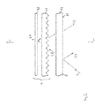
- Fig. 2 is a - very schematic - sketch to a cross section through the lamp head 72 shown.
- the luminaire has an optical reflection and transmission element 2, which reflects a first part L1 of the light L generated by the LED light source 1 and transmits a second part L2 of the light L.
- the design is such that the first part L1 is provided for direct illumination, in particular the working surface 81.
- the optical reflection and transmission element 2 is preferably made of plastic, in particular of PMMA.
- the optical reflection and transmission element 2 preferably comprises a plate, in particular a plate with two large, planar surfaces or consists of such a plate. This plate can be anti-reflective or non-reflective.
- the lamp has a glare and deflection unit 4, which is configured for glare and deflection of the second part L2 of the light L.
- optical reflection and transmission element 2 and the Entblendungsund deflecting unit 4 may be formed in the sense of a mirror-launcher system, a kind of "mirror unit" of the lamp.
- the optical reflection and transmission element 2 and the glare and deflection unit 4 are arranged on the lamp head 72 or integrated in this.
- the design is preferably such that the second part L2 of the light L is at least partially directed back to the reflection and transmission element 2 by the glare and deflection unit 4. Accordingly, this light is subsequently transmitted at least partially through the reflection and transmission element 2, so that a portion L3 of the second light L2 leaves the reflection and transmission element 2 and, in addition to the first part L1 , for generating the direct illumination, especially the work surface 81 is available or serves.
- the light emitted by the light to produce a direct illumination thus consists of two components: a first light component in the form of the first part L1 of the light L generated by the LED light source 1 as a reflection image of the reflection and transmission element 2 and a second Light component in the form of the proportion L3 of the second light L2, which exudes through the micro prism plate 41 glare back out of the reflection and transmission element 2 down.
- the Entblendungs- and deflection unit 4 comprises a micro prism plate 41 for glare and a reflective plate 42 for deflecting the second portion L2 of the light L, preferably the micro prism plate 41 between the reflection and transmission element 2 on the one hand and the reflective plate 42 of the glare - And deflecting unit 4 on the other hand is arranged.
- the glare and deflection unit 4 may consist of the microprism plate 41 and the reflective plate 42.
- a portion L4 of the second light L2 is delivered upward and is available for generating indirect illumination.
- a suitable illumination of an environment of the workstation can also be generated.
- a particularly suitable reflection property of the plate 42 can be achieved if it is diffusely reflecting, in particular diffusely highly reflecting or opal, that is to say slightly translucent.
- the reflection and transmission element 2 has a light receiving surface 21 for receiving the light L generated by the LED light source 1.
- the light-receiving surface 21 preferably has a surface area of at least 50 cm 2 , preferably of at least 100 cm 2 .
- the luminaire is preferably designed such that the light L generated by the LED light source 1 irradiates the predominant portion of the light receiving surface 21, for example at least 80% of the light receiving surface 21.
- the design is such that virtually the entire light receiving surface 21 of the light L is irradiated.
- the LED light source 1 can be designed accordingly for this purpose with the aid of the above-mentioned lens and / or the reflector.
- the light receiving surface 21 may advantageously be provided by a surface of the reflection and transmission element 2, in particular by a u downwardly facing surface of the reflection and transmission element. 2
- the reflection and transmission element 2 is preferably designed such that the second part L2 of the light L generated by the LED light source 1 has a greater intensity than the first part L1 of the light L. As a result, the risk of the emergence of reflected glare on the work surface 81 is basically reduced.
- the intensity of the first part L1 of the light L in relation to the intensity of the light L generated by the LED light source 1 , can be set virtually arbitrarily precisely by the degree or type of partial vapor deposition. In this way, the risk of the emergence of reflected glare on the work surface 81 can be reduced almost arbitrarily precisely.
- the luminaire is designed such that a predominant part of the light L generated by the LED light source 1 reaches the plate 42 of the glare and deflection unit 4.
- the plate 22 of the reflection and transmission element 2, the micro-prism plate 41 and the plate 42 of the anti-dazzle and deflection unit 4 are arranged in layers, in particular parallel to one another.
- the said components 22, 41, 42 may be designed in particular plan and in each case be arranged horizontally. But it is also an obliquely inclined arrangement possible. Also, said components 22, 41, 42 may be curved.
- the light emitted by the lamp for establishing a direct illumination from a first light component in the form of the first part L1 of the light L generated by the LED light source 1 sets as a reflection image of the reflection and transmission element 2 and a second light component in the form of the portion L3 of the second light L2 together.
- the ratio of the two light components u. a. influenced by the arrangement of the glare and deflection unit 4.
Landscapes
- Engineering & Computer Science (AREA)
- General Engineering & Computer Science (AREA)
- Non-Portable Lighting Devices Or Systems Thereof (AREA)
Abstract
Description
- Die Erfindung betrifft eine Leuchte mit einer LED-Lichtquelle (LED: Licht emittierende Diode) zur Erzeugung eines Lichts und mit einem optischen Reflexions-und Transmissionselement, das einen ersten Teil des Lichts reflektiert und einen zweiten Teil des Lichts transmittiert.
- Aus dem Stand der Technik ist eine derartige Leuchte in Form einer Stehleuchte bekannt, die zur Beleuchtung eines Büro-Arbeitsplatzes bzw. einer entsprechenden Tischoberfläche vorgesehen ist. Die LED-Lichtquelle ist dabei quasi als "Lichtwerfer" an dem Ständer der Stehleuchte angeordnet und das optische Element an einem Art Leuchtenkopf, der sich am oberen Ende des Ständers befindet. Die LED-Lichtquelle gibt das von ihr erzeugte Licht nach schräg oben ab, so dass es auf das optische Element trifft. Es handelt sich somit quasi um ein Spiegel-Werfer-System. Das optische Element ist teiltransparent gestaltet. Hierdurch wird einerseits - durch den reflektierten Anteil des Lichts - eine direkte Beleuchtung der Tischoberfläche ermöglicht und andererseits - durch den durchgelassenen Anteil des Lichts - eine Lichtabgabe nach oben für eine indirekte Beleuchtung des umgebenden Raums.
- Aufgrund der LED-Lichtquelle wird das Licht - im Vergleich zu einer Leuchtstoffröhre - gebündelter abgegeben und so eine besonders hohe Effizienz erzielt. Außerdem ist ein einfacher Aufbau der Stehleuchte ermöglicht.
- Das optische Element der bekannten Stehleuchte weist eine Aluminium-bedampfte PC-Folie (PC: Polycarbonat) auf. Hierdurch kommt es zu hohen Leuchtdichten bzw. zu einem Mangel an flächigem Licht im Bereich der beleuchteten Fläche. Dadurch ist eine hohe Wahrscheinlichkeit gegeben, dass es beientsprechenden Oberflächen, die sich auf der beleuchteten Tischoberfläche befinden, zu Reflexblendungen kommt.
- Der Erfindung liegt die Aufgabe zugrunde, eine entsprechende verbesserte Leuchte anzugeben. Insbesondere soll die Gefahr von Reflexblendungen vermindert sein. Diese Aufgabe wird gemäß der Erfindung mit dem in dem unabhängigen Anspruch genannten Gegenstand gelöst. Besondere Ausführungsarten der Erfindung sind in den abhängigen Ansprüchen angegeben.
- Gemäß der Erfindung ist eine Leuchte vorgesehen, die eine LED-Lichtquelle zur Erzeugung eines Lichts aufweist, sowie ein optisches Reflexions- und Transmissions-Element, das einen ersten Teil des Lichts reflektiert und einen zweiten Teil des Lichts transmittiert. Der erste Teil des Lichts ist dabei zur Erzeugung einer direkten Beleuchtung vorgesehen. Weiterhin weist die Leuchte eine Entblendungs- und Umlenkeinheit zur Entblendung und Umlenklung des zweiten Teils des Lichts auf.
- Der zweite Teil des Lichts ist dementsprechend nach Wechselwirkung mit der Entblendungs- und Umlenkeinheit entblendet und umgelenkt, so dass sich durch Nutzung des umgelenkten Lichtanteils die Gefahr einer Entstehung von Reflexblendung vermindern lässt.
- Vorzugsweise ist die Leuchte derart gestaltet ist, dass der zweite Teil des Lichts durch die Entblendungs- und Umlenkeinheit zumindest teilweise wieder zurück auf das Reflexions- und Transmissions-Element gelenkt wird. Hierdurch ist eine besonders kleine bzw. flache Ausführung der Leuchte ermöglicht.
- Vorzugsweise weist die Leuchte weiterhin einen Ständer und einen Leuchtenkopf auf, der vorzugsweise quer von dem Ständer abstehend angeordnet ist, wobei die LED-Lichtquelle an dem Ständer angeordnet oder in diesen integriert ist und das optische Reflexions- und Transmissionselement und die Entblendungs- und Umlenkeinheit an dem Leuchtenkopf angeordnet oder in diesen integriert sind. Hierdurch ist eine besonders einfache Gestaltung der Leuchte ermöglicht.
- Vorzugsweise weist die Entblendungs- und Umlenkeinheit eine Mikroprismenplatte oder eine teiltransparente Kalottenstruktur auf. Hierdurch ist eine besonders effektive Entblendungswirkung ermöglicht.
- Weiterhin vorzugsweise weist die Entblendungs- und Umlenkeinheit eine reflektierende Platte auf. Hierdurch ist eine effektive Umlenkung ermöglicht.
- Vorzugsweise ist die Platte der Entblendungs- und Umlenkeinheit derart gestaltet, dass sie den zweiten Teil des Lichts teilweise durchlässt und teilweise reflektiert. Aufgrund der teilweisen Durchlässigkeit lässt sich vorteilhaft eine Abgabe von Licht zur Erzeugung einer indirekten Beleuchtung bewirken.
- Vorzugsweise ist die Platte der Entblendungs- und Umlenkeinheit diffus reflektierend, insbesondere hochreflektierend oder opal.
- Eine besonders effektive Entblendung und Umlenkung ist ermöglicht, wenn die Mikroprismenplatte zwischen dem Reflexions- und Transmissions-Element und der Platte der Entblendungs- und Umlenkeinheit angeordnet ist.
- Vorzugsweise weist das Reflexions- und Transmissions-Element eine Lichtempfangsfläche zum Empfangen des Lichts auf, wobei die Lichtempfangsfläche zumindest in erster Näherung plan oder gewölbt gestaltet ist. Hierdurch lässt sich bei besonders geringer Blendungsgefahr eine besonders geeignete Lichtabgabe der Leuchte erzielen. Dabei weist die Lichtempfangsfläche vorteilhaft eine Oberfläche von wenigstens 50 cm2 auf, vorzugsweise von wenigstens 100 cm2.
- Eine besonders gute Effizienz ist dabei ermöglicht, wenn die Leuchte derart gestaltet ist, dass das von der LED-Lichtquelle 1 erzeugte Licht wenigstens 80% der Lichtempfangsfläche bestrahlt.
- Vorzugsweise weist das Reflexions- und Transmissions-Element eine Platte aus Kunststoff, insbesondere aus PMMA (Polymethylmethacrylat) oder aus Glas auf oder besteht aus einer solchen, wobei die Lichtempfangsfläche eine Fläche dieser Platte des Reflexions- und Transmissions-Elements ist. Hierdurch sind besonders geeignete optische Eigenschaften des Reflexions- und Transmissions-Elements ermöglicht.
- Vorzugsweise ist die Lichtempfangsfläche teilbedampft. Auf diese Weise lässt sich das Verhältnis der Intensitäten des ersten Teils des Lichts und des zweiten Teils des Lichts quasi beliebig genau vorgeben. Insbesondere kann der erste Teil des Lichts, also der an dem optischen Reflexions- und Transmissionselement reflektierte Teil in seiner Intensität gezielt beeinflusst werden.
- Eine besonders flache Bauform des Leuchtenkopfes ist ermöglicht, wenn die Platte des Reflexions- und Transmissions-Elements, die Mikroprismenplatte und die Platte der Entblendungs- und Umlenkeinheit schichtartig, insbesondere parallel zueinander angeordnet sind.
- Besonders gut eignet sich die Leuchte in Form einer Stehleuchte und/oder Arbeitsplatzleuchte.
- Die Erfindung wird im Folgenden anhand eines Ausführungsbeispiels und mit Bezug auf die Zeichnungen näher erläutert. Es zeigen:
- Fig. 1
- eine Skizze zu dem Ausführungsbeispiel einer erfindungsgemäßen Leuchte und
- Fig. 2
- eine Skizze zum Aufbau des optischen Reflexions- und Transmissions-Elements und der Entblendungs- und Umlenkeinheit der Leuchte.
-
Fig. 1 zeigt eine Skizze einer erfindungsgemäßen Leuchte. Bei dem hier gezeigten Ausführungsbeispiel ist die Leuchte eine Stehleuchte mit einem Ständer 71 und einem Leuchtenkopf 72. Der Ständer 71 erstreckt sich dabei in vertikaler Richtung von unten u nach oben o, wie durch einen Doppelpfeil angedeutet. Der Leuchtenkopf 72 ist an einem oberen Endbereich des Ständers 71 angeordnet, insbesondere quer abstehend. Der Ständer 71 kann an einem unteren Endbereich einen (nicht gesondert skizzierten) Fuß mit einer Standfläche zum Aufstellen der Stehleuchte aufweisen. - Eine erfindungsgemäße Leuchte kann auch für eine andere Orientierung gegenüber der Vertikalen vorgesehen sein. Zur leichteren Darstellung ist jedoch im Folgenden von der hier gezeigten Orientierung ausgegangen. Gegebenenfalls sind die Richtungsangaben entsprechend umzudeuten.
- Die Leuchte ist als Arbeitsplatzleuchte gestaltet und dient zur Beleuchtung eines Arbeitsplatzes, insbesondere einer Oberfläche in Form einer Arbeitsfläche 81 eines Arbeitstisches 8. Die Leuchte kann alternativ auch als Tischleuchte gestaltet sein, bei der der Ständer zur Befestigung an einem Gegenstand, beispielsweise an dem Arbeitstisch 8 ausgebildet ist oder zum Aufstellen auf die Arbeitsfläche 81 oder eine angrenzende Oberfläche des Arbeitstisches 8 ausgebildet ist.
- Die Leuchte weist eine LED-Lichtquelle 1 zur Erzeugung eines Lichts L auf. Die LED-Lichtquelle 1 umfasst wenigstens eine LED. Die LED-Lichtquelle 1 ist vorzugsweise an dem Ständer 71 angeordnet oder in diesen integriert gestaltet, insbesondere auf einem Niveau unterhalb des Leuchtenkopfs 72. Die LED-Lichtquelle 1 kann quasi eine "Werfer-Einheit" der Leuchte bilden.
- Die Gestaltung ist vorzugsweise derart, dass das Licht L von der LED-Lichtquelle 1 in Richtung auf den Leuchtenkopf 72 abgestrahlt wird. Die LED-Lichtquelle 1 kann hierzu (in den Figuren nicht gezeigt) eine Linse und/oder einen Reflektor aufweisen.
- In
Fig. 2 ist eine - sehr schematische - Skizze zu einem Querschnitt durch den Leuchtenkopf 72 gezeigt. - Die Leuchte weist ein optisches Reflexions- und Transmissionselement 2 auf, das einen ersten Teil L1 des von der LED-Lichtquelle 1 erzeugten Lichts L reflektiert und einen zweiten Teil L2 des Lichts L transmittiert. Die Gestaltung ist dabei derart, dass der erste Teil L1 zur direkten Beleuchtung, insbesondere der Arbeitsfläche 81 vorgesehen ist.
- Das optische Reflexions- und Transmissionselement 2 ist vorzugsweise aus Kunststoff, insbesondere aus PMMA gefertigt. Das optische Reflexions- und Transmissionselement 2 umfasst vorzugsweise eine Platte, insbesondere eine Platte mit zwei großen, planen Oberflächen bzw. besteht aus einer solchen Platte. Diese Platte kann dabei entspiegelt oder nicht entspiegelt sein.
- Weiterhin weist die Leuchte eine Entblendungs- und Umlenkeinheit 4 auf, die zur Entblendung und Umlenkung des zweiten Teils L2 des Lichts L ausgestaltet ist.
- Durch das optisches Reflexions- und Transmissionselement 2 und die Entblendungsund Umlenkeinheit 4 kann quasi im Sinn eines Spiegel-Werfer-Systems eine Art "Spiegeleinheit" der Leuchte gebildet sein.
- Beim Ausführungsbeispiel sind das optische Reflexions- und Transmissionselement 2 und die Entblendungs- und Umlenkeinheit 4 an dem Leuchtenkopf 72 angeordnet oder in diesen integriert.
- Wie in
Fig. 2 angedeutet, ist die Gestaltung vorzugsweise derart, dass der zweite Teil L2 des Lichts L durch die Entblendungs- und Umlenkeinheit 4 zumindest teilweise wieder zurück auf das Reflexions- und Transmissions-Element 2 gelenkt wird. Dieses Licht wird dementsprechend im Weiteren zumindest teilweise durch das Reflexionsund Transmissions-Element 2 transmittiert, so dass ein Anteil L3 des zweiten Lichts L2 das Reflexions- und Transmissions-Element 2 verlässt und - zusätzlich zu dem ersten Teil L1 - zur Erzeugung der direkten Beleuchtung, insbesondere der Arbeitsfläche 81 zur Verfügung steht bzw. dient. - Das von der Leuchte abgegeben Licht zur Erzeugung einer direkten Beleuchtung besteht also aus zwei Komponenten: einer ersten Lichtkomponente in Form des ersten Teils L1 des von der LED-Lichtquelle 1 erzeugten Lichts L als Reflexbild von dem Reflexions- und Transmissions-Element 2 und einer zweiten Lichtkomponente in Form des Anteils L3 des zweiten Lichts L2, die durch die Mikroprismenplatte 41 entblendet wieder aus dem Reflexions- und Transmissions-Element 2 nach unten austritt.
- Da der Anteil L3 aufgrund der optischen Wirkung der Entblendungs- und Umlenkeinheit 4 entblendet ist, wird hierdurch die Gefahr einer Entstehung von Reflexblendung durch einen mehr oder weniger spiegelnden Gegenstand, der sich auf der Arbeitsfläche 81 befindet, vermindert.
- Vorzugsweise umfasst die Entblendungs- und Umlenkeinheit 4 eine Mikroprismenplatte 41 zur Entblendung sowie eine reflektierende Platte 42 zur Umlenkung des zweiten Teils L2 des Lichts L, wobei vorzugsweise die Mikroprismenplatte 41 zwischen dem Reflexions- und Transmissions-Element 2 einerseits und der reflektierenden Platte 42 der Entblendungs- und Umlenkeinheit 4 andererseits angeordnet ist. Die Entblendungs- und Umlenkeinheit 4 kann aus der Mikroprismenplatte 41 und der reflektierenden Platte 42 bestehen.
- Wenn die Platte 42 der Entblendungs- und Umlenkeinheit 4 so gestaltet ist, dass sie den zweiten Teil L2 des Lichts L teilweise durchlässt und teilweise reflektiert, wird ein Anteil L4 des zweiten Lichts L2 nach oben abgegeben und steht zur Erzeugung einer indirekten Beleuchtung zur Verfügung. Hierdurch lässt sich neben der direkten Beleuchtung der Arbeitsfläche 81 auch eine geeignete Beleuchtung einer Umgebung des Arbeitsplatzes erzeugen.
- Eine besonders geeignete Reflexionseigenschaft der Platte 42 lässt sich erzielen, wenn sie diffus reflektierend, insbesondere diffus hochreflektierend ist oder opal, also leicht lichtdurchlässig.
- Vorzugsweise weist das Reflexions- und Transmissionselement 2 eine Lichtempfangsfläche 21 zum Empfangen des von der LED-Lichtquelle 1 erzeugten Lichts L auf. Die Lichtempfangsfläche 21 weist vorzugsweise eine Oberfläche von wenigstens 50 cm2, vorzugsweise von wenigstens 100 cm2 auf. Dabei ist die Leuchte vorzugsweise so gestaltet, dass das von der LED-Lichtquelle 1 erzeugte Licht L den überwiegenden Anteil der Lichtempfangsfläche 21 bestrahlt, beispielsweise wenigstens 80% der Lichtempfangsfläche 21. Vorzugsweise ist die Gestaltung derart, dass praktisch die gesamte Lichtempfangsfläche 21 von dem Licht L bestrahlt wird.
- Insbesondere kann die LED-Lichtquelle 1 hierzu mithilfe der oben bereits erwähnten Linse und/oder des Reflektors entsprechend gestaltet sein.
- Die Lichtempfangsfläche 21 kann vorteilhaft durch eine Fläche des Reflexions- und Transmissions-Elements 2 gegeben sein, insbesondere durch eine nach unten u weisende Fläche des Reflexions- und Transmissions-Elements 2.
- Das Reflexions- und Transmissions-Element 2 ist vorzugsweise derart gestaltet, dass der zweite Teil L2 des von der LED-Lichtquelle 1 erzeugten Lichts L eine größere Intensität aufweist als der erste Teil L1 des Lichts L. Hierdurch ist die Gefahr einer Entstehung von Reflexblendung an der Arbeitsfläche 81 grundsätzlich verringert.
- Wenn die Lichtempfangsfläche 21 teilbedampft gestaltet ist, lässt sich durch das Maß bzw. die Art der Teilbedampfung die Intensität des ersten Teils L1 des Lichts L, im Verhältnis zu der Intensität des von der LED-Lichtquelle 1 erzeugten Lichts L, quasi beliebig genau einstellen. Auf diese Weise lässt sich die Gefahr einer Entstehung von Reflexblendung auf der Arbeitsfläche 81 quasi beliebig genau verringern.
- Vorzugsweise ist die Leuchte derart gestaltet, dass ein überwiegender Teil des von der LED-Lichtquelle 1 erzeugten Lichts L bis zu der Platte 42 der Entblendungs- und Umlenkeinheit 4 gelangt.
- Beim gezeigten Beispiel sind die Platte 22 des Reflexions- und Transmissions-Elements 2, die Mikroprismenplatte 41 und die Platte 42 der Entblendungs- und Umlenkeinheit 4 schichtartig, insbesondere parallel zueinander angeordnet. Hierdurch ist eine besonders flache Bauform des Leuchtenkopfs 72 ermöglicht. Die genannten Bauteile 22, 41, 42 können insbesondere plan gestaltet sein und dabei jeweils horizontal angeordnet sein. Es ist aber auch eine schräg geneigte Anordnung möglich. Auch können die genannten Bauteile 22, 41, 42 gewölbt geformt sein.
- Wie weiter oben angegeben, setzt sich das von der Leuchte abgegeben Licht zur Erzeugung einer direkten Beleuchtung aus einer ersten Lichtkomponente in Form des ersten Teils L1 des von der LED-Lichtquelle 1 erzeugten Lichts L als Reflexbild von dem Reflexions- und Transmissions-Element 2 und einer zweiten Lichtkomponente in Form des Anteils L3 des zweiten Lichts L2 zusammen.
- Die Verteilcharakteristik der ersten Lichtkomponente lässt sich durch folgende Faktoren beeinflussen:
- die Gestaltung des Reflexions- und Transmissions-Elements 2, insbesondere eine mögliche Wölbung des Reflexions- und Transmissions-Elements 2 bzw. der Lichtempfangsfläche 21,
- Anordnung des Reflexions- und Transmissions-Elements 2 in Relation zu der Position der LED-Lichtquelle 1,
- die Verteilcharakteristik des von der LED-Lichtquelle 1 erzeugten Lichts L,
- gegebenenfalls eine Teilbedampfung der Lichtempfangsfläche 21 des Reflexions- und Transmissions-Elements 2.
- Die Verteilcharakteristik der zweiten Lichtkomponente lässt sich durch folgende Faktoren beeinflussen:
- die Anordnung der Entblendungs- und Umlenkeinheit 4
- Gestaltung der Entblendungs- und Umlenkeinheit 4, insbesondere die Oberflächeneigenschaft der Platte 42 der Entblendungs- und Umlenkeinheit 4.
- Das Verhältnis der beiden Lichtkomponenten wird u. a. durch die Anordnung der Entblendungs- und Umlenkeinheit 4 beeinflusst.
Claims (15)
- Leuchte, aufweisend- eine LED-Lichtquelle (1) zur Erzeugung eines Lichts (L),- ein optisches Reflexions- und Transmissions-Element (2), das einen ersten Teil (L1) des Lichts (L) reflektiert und einen zweiten Teil (L2) des Lichts (L) transmittiert,
wobei der erste Teil (L1) des Lichts (L) zur Erzeugung einer direkten Beleuchtung vorgesehen ist,
dadurch gekennzeichnet,
dass die Leuchte weiterhin- eine Entblendungs- und Umlenkeinheit (4) zur Entblendung und Umlenkung des zweiten Teils (L2) des Lichts (L) aufweist. - Leuchte nach Anspruch 1,
die derart gestaltet ist, dass der zweite Teil (L2) des Lichts (L) durch die Entblendungs- und Umlenkeinheit (4) zumindest teilweise wieder zurück auf das Reflexions- und Transmissions-Element (2) gelenkt wird. - Leuchte nach Anspruch 1 oder 2,
weiterhin aufweisend- einen Ständer (71) und- einen Leuchtenkopf (72), der vorzugsweise quer von dem Ständer (71) abstehend angeordnet ist,wobei die LED-Lichtquelle (1) an dem Ständer (71) angeordnet oder in diesen integriert ist und das optische Reflexions- und Transmissionselement (2) und die Entblendungs- und Umlenkeinheit (4) an dem Leuchtenkopf (72) angeordnet oder in diesen integriert sind. - Leuchte nach einem der vorhergehenden Ansprüche,
bei der die Entblendungs- und Umlenkeinheit (4) eine Mikroprismenplatte (41) aufweist. - Leuchte nach einem der vorhergehenden Ansprüche,
bei der die Entblendungs- und Umlenkeinheit (4) eine reflektierende Platte (42) aufweist. - Leuchte nach Anspruch 5,
bei der die Platte (42) der Entblendungs- und Umlenkeinheit (4) derart gestaltet ist, dass sie den zweiten Teil (L2) des Lichts (L) teilweise durchlässt und teilweise reflektiert. - Leuchte nach Anspruch 5 oder 6,
bei der die Platte (42) der Entblendungs- und Umlenkeinheit (4) diffus reflektierend, insbesondere hochreflektierend oder opal ist. - Leuchte nach einem der Ansprüche 5 bis 7, jeweils in seinem Rückbezug auf den Anspruch 4,
bei der die die Mikroprismenplatte (41) zwischen dem Reflexions- und Transmissions-Element (2) und der Platte (42) der Entblendungs- und Umlenkeinheit (4) angeordnet ist. - Leuchte nach einem der vorhergehenden Ansprüche,
bei der das Reflexions- und Transmissions-Element (2) eine Lichtempfangsfläche (21) zum Empfangen des Lichts (L) aufweist, wobei die Lichtempfangsfläche (21) zumindest in erster Näherung plan oder gewölbt gestaltet ist. - Leuchte nach Anspruch 9,
bei der die Lichtempfangsfläche (21) eine Oberfläche von wenigstens 50 cm2 aufweist, vorzugsweise von wenigstens 100 cm2. - Leuchte nach Anspruch 9 oder 10,
die derart gestaltet ist, dass das von der LED-Lichtquelle (1) erzeugte Licht (L) wenigstens 80% der Lichtempfangsfläche (21) bestrahlt. - Leuchte nach einem der Ansprüche 9 bis 11,
bei der das Reflexions- und Transmissions-Element (2) eine Platte (22) aus Kunststoff, insbesondere aus PMMA oder aus Glas aufweist oder aus einer solchen besteht, wobei die Lichtempfangsfläche (21) eine Fläche dieser Platte (22) des Reflexions- und Transmissions-Elements (2) ist. - Leuchte nach Anspruch 12,
bei der die Lichtempfangsfläche (21) teilbedampft ist. - Leuchte mit den in den Ansprüchen 4, 5 und 12 genannten Merkmalen,
bei der die Platte (22) des Reflexions- und Transmissions-Elements (2), die Mikroprismenplatte (41) und die Platte (42) der Entblendungs- und Umlenkeinheit (4) schichtartig, insbesondere parallel zueinander angeordnet sind. - Leuchte nach einem der vorhergehenden Ansprüche,
in Form einer Stehleuchte und/oder Arbeitsplatzleuchte.
Applications Claiming Priority (1)
| Application Number | Priority Date | Filing Date | Title |
|---|---|---|---|
| DE102012219710.9A DE102012219710A1 (de) | 2012-10-29 | 2012-10-29 | Leuchte mit LED-Lichtquelle |
Publications (2)
| Publication Number | Publication Date |
|---|---|
| EP2725286A1 true EP2725286A1 (de) | 2014-04-30 |
| EP2725286B1 EP2725286B1 (de) | 2015-12-30 |
Family
ID=49485621
Family Applications (1)
| Application Number | Title | Priority Date | Filing Date |
|---|---|---|---|
| EP13190472.4A Active EP2725286B1 (de) | 2012-10-29 | 2013-10-28 | Leuchte mit LED-Lichtquelle |
Country Status (2)
| Country | Link |
|---|---|
| EP (1) | EP2725286B1 (de) |
| DE (1) | DE102012219710A1 (de) |
Families Citing this family (1)
| Publication number | Priority date | Publication date | Assignee | Title |
|---|---|---|---|---|
| CN109506211A (zh) * | 2018-12-24 | 2019-03-22 | 王川 | 一种防眩目装置 |
Citations (2)
| Publication number | Priority date | Publication date | Assignee | Title |
|---|---|---|---|---|
| WO2012052937A1 (en) * | 2010-10-22 | 2012-04-26 | Koninklijke Philips Electronics N.V. | Arrangement for a low loss luminaire |
| WO2012113085A1 (de) * | 2011-02-22 | 2012-08-30 | Belux Ip Ag | Beleuchtungseinrichtung für räume zur indirektbeleuchtung eines nutzungsareals |
Family Cites Families (1)
| Publication number | Priority date | Publication date | Assignee | Title |
|---|---|---|---|---|
| ATE111580T1 (de) * | 1989-08-17 | 1994-09-15 | Siemens Ag | Arbeitsplatzleuchte. |
-
2012
- 2012-10-29 DE DE102012219710.9A patent/DE102012219710A1/de not_active Withdrawn
-
2013
- 2013-10-28 EP EP13190472.4A patent/EP2725286B1/de active Active
Patent Citations (2)
| Publication number | Priority date | Publication date | Assignee | Title |
|---|---|---|---|---|
| WO2012052937A1 (en) * | 2010-10-22 | 2012-04-26 | Koninklijke Philips Electronics N.V. | Arrangement for a low loss luminaire |
| WO2012113085A1 (de) * | 2011-02-22 | 2012-08-30 | Belux Ip Ag | Beleuchtungseinrichtung für räume zur indirektbeleuchtung eines nutzungsareals |
Also Published As
| Publication number | Publication date |
|---|---|
| EP2725286B1 (de) | 2015-12-30 |
| DE102012219710A1 (de) | 2014-04-30 |
Similar Documents
| Publication | Publication Date | Title |
|---|---|---|
| EP0846915A1 (de) | Innenraumleuchte | |
| EP2986893B1 (de) | Leuchte | |
| DE102017116885B4 (de) | Leuchtmittel und Linse für ein Leuchtmittel | |
| EP2725286B1 (de) | Leuchte mit LED-Lichtquelle | |
| DE4312889B4 (de) | Vorwiegend direkt strahlende Leuchte mit einem abgehängten Lichtleitkörper | |
| WO2021058167A1 (de) | Leuchte mit bereich zur flächigen lichtabgabe | |
| DE202015101870U1 (de) | Optisches System sowie Anordnung zur Lichtabgabe | |
| DE102016201347B4 (de) | Optisches System zum Beeinflussen der Lichtabgabe einer Lichtquelle | |
| EP3058411A1 (de) | Optisches system für eine led-lichtquelle sowie leuchte mit einem solchen optischen system | |
| EP2989378B1 (de) | Led-leuchte mit unterschiedlich einstellbaren lichtverteilungen | |
| DE202012104953U1 (de) | Leuchte mit einem gekrümmten Lichtleitelement | |
| DE202010008598U1 (de) | Optisches System und Leuchte für direkte und indirekte Beleuchtung | |
| AT16724U1 (de) | Lichtleiterelement sowie Leuchte mit einem Lichtleiterelement | |
| EP4168711B1 (de) | Anordnung zur lichtabgabe und leuchte | |
| DE102018119606A1 (de) | Optisches Element für eine Leuchte, insbesondere Büroleuchte, sowie Leuchte | |
| DE102018123128B4 (de) | Leuchte mit plattenförmigem Lichtleitelement | |
| EP2860444B1 (de) | LED-Rasterleuchte | |
| EP3329178B1 (de) | Lichtleiterelement | |
| AT15785U1 (de) | Optisches Element für eine Lichtquelle einer Leuchte, sowie Leuchte | |
| EP3889499A1 (de) | Leuchte mit lichtquelle und zugehöriger optik | |
| EP3112747A1 (de) | Optisches element zur beeinflussung der lichtabgabe einer länglichen lichtquelle | |
| AT18290U1 (de) | Notlichtleuchte | |
| DE102012202121A1 (de) | Leuchte | |
| EP1936410A1 (de) | Lichtleitplatte | |
| DE102016207137A1 (de) | Anordnung zur Lichtabgabe |
Legal Events
| Date | Code | Title | Description |
|---|---|---|---|
| PUAI | Public reference made under article 153(3) epc to a published international application that has entered the european phase |
Free format text: ORIGINAL CODE: 0009012 |
|
| 17P | Request for examination filed |
Effective date: 20131028 |
|
| AK | Designated contracting states |
Kind code of ref document: A1 Designated state(s): AL AT BE BG CH CY CZ DE DK EE ES FI FR GB GR HR HU IE IS IT LI LT LU LV MC MK MT NL NO PL PT RO RS SE SI SK SM TR |
|
| AX | Request for extension of the european patent |
Extension state: BA ME |
|
| 17P | Request for examination filed |
Effective date: 20140922 |
|
| RBV | Designated contracting states (corrected) |
Designated state(s): AL AT BE BG CH CY CZ DE DK EE ES FI FR GB GR HR HU IE IS IT LI LT LU LV MC MK MT NL NO PL PT RO RS SE SI SK SM TR |
|
| GRAP | Despatch of communication of intention to grant a patent |
Free format text: ORIGINAL CODE: EPIDOSNIGR1 |
|
| RIC1 | Information provided on ipc code assigned before grant |
Ipc: F21W 131/402 20060101ALN20150626BHEP Ipc: F21S 6/00 20060101AFI20150626BHEP Ipc: F21V 7/00 20060101ALI20150626BHEP Ipc: F21V 7/22 20060101ALN20150626BHEP Ipc: F21Y 101/02 20060101ALN20150626BHEP Ipc: F21V 5/00 20150101ALN20150626BHEP |
|
| INTG | Intention to grant announced |
Effective date: 20150727 |
|
| GRAS | Grant fee paid |
Free format text: ORIGINAL CODE: EPIDOSNIGR3 |
|
| GRAA | (expected) grant |
Free format text: ORIGINAL CODE: 0009210 |
|
| AK | Designated contracting states |
Kind code of ref document: B1 Designated state(s): AL AT BE BG CH CY CZ DE DK EE ES FI FR GB GR HR HU IE IS IT LI LT LU LV MC MK MT NL NO PL PT RO RS SE SI SK SM TR |
|
| REG | Reference to a national code |
Ref country code: GB Ref legal event code: FG4D Free format text: NOT ENGLISH |
|
| REG | Reference to a national code |
Ref country code: CH Ref legal event code: EP |
|
| REG | Reference to a national code |
Ref country code: AT Ref legal event code: REF Ref document number: 767658 Country of ref document: AT Kind code of ref document: T Effective date: 20160115 |
|
| REG | Reference to a national code |
Ref country code: IE Ref legal event code: FG4D Free format text: LANGUAGE OF EP DOCUMENT: GERMAN |
|
| REG | Reference to a national code |
Ref country code: CH Ref legal event code: NV Representative=s name: WEINMANN ZIMMERLI, CH |
|
| REG | Reference to a national code |
Ref country code: DE Ref legal event code: R096 Ref document number: 502013001695 Country of ref document: DE |
|
| REG | Reference to a national code |
Ref country code: LT Ref legal event code: MG4D |
|
| PG25 | Lapsed in a contracting state [announced via postgrant information from national office to epo] |
Ref country code: LT Free format text: LAPSE BECAUSE OF FAILURE TO SUBMIT A TRANSLATION OF THE DESCRIPTION OR TO PAY THE FEE WITHIN THE PRESCRIBED TIME-LIMIT Effective date: 20151230 Ref country code: NO Free format text: LAPSE BECAUSE OF FAILURE TO SUBMIT A TRANSLATION OF THE DESCRIPTION OR TO PAY THE FEE WITHIN THE PRESCRIBED TIME-LIMIT Effective date: 20160330 Ref country code: HR Free format text: LAPSE BECAUSE OF FAILURE TO SUBMIT A TRANSLATION OF THE DESCRIPTION OR TO PAY THE FEE WITHIN THE PRESCRIBED TIME-LIMIT Effective date: 20151230 |
|
| REG | Reference to a national code |
Ref country code: NL Ref legal event code: MP Effective date: 20151230 |
|
| PG25 | Lapsed in a contracting state [announced via postgrant information from national office to epo] |
Ref country code: RS Free format text: LAPSE BECAUSE OF FAILURE TO SUBMIT A TRANSLATION OF THE DESCRIPTION OR TO PAY THE FEE WITHIN THE PRESCRIBED TIME-LIMIT Effective date: 20151230 Ref country code: LV Free format text: LAPSE BECAUSE OF FAILURE TO SUBMIT A TRANSLATION OF THE DESCRIPTION OR TO PAY THE FEE WITHIN THE PRESCRIBED TIME-LIMIT Effective date: 20151230 Ref country code: SE Free format text: LAPSE BECAUSE OF FAILURE TO SUBMIT A TRANSLATION OF THE DESCRIPTION OR TO PAY THE FEE WITHIN THE PRESCRIBED TIME-LIMIT Effective date: 20151230 Ref country code: GR Free format text: LAPSE BECAUSE OF FAILURE TO SUBMIT A TRANSLATION OF THE DESCRIPTION OR TO PAY THE FEE WITHIN THE PRESCRIBED TIME-LIMIT Effective date: 20160331 Ref country code: FI Free format text: LAPSE BECAUSE OF FAILURE TO SUBMIT A TRANSLATION OF THE DESCRIPTION OR TO PAY THE FEE WITHIN THE PRESCRIBED TIME-LIMIT Effective date: 20151230 |
|
| PG25 | Lapsed in a contracting state [announced via postgrant information from national office to epo] |
Ref country code: NL Free format text: LAPSE BECAUSE OF FAILURE TO SUBMIT A TRANSLATION OF THE DESCRIPTION OR TO PAY THE FEE WITHIN THE PRESCRIBED TIME-LIMIT Effective date: 20151230 |
|
| PG25 | Lapsed in a contracting state [announced via postgrant information from national office to epo] |
Ref country code: ES Free format text: LAPSE BECAUSE OF FAILURE TO SUBMIT A TRANSLATION OF THE DESCRIPTION OR TO PAY THE FEE WITHIN THE PRESCRIBED TIME-LIMIT Effective date: 20151230 Ref country code: IT Free format text: LAPSE BECAUSE OF FAILURE TO SUBMIT A TRANSLATION OF THE DESCRIPTION OR TO PAY THE FEE WITHIN THE PRESCRIBED TIME-LIMIT Effective date: 20151230 Ref country code: CZ Free format text: LAPSE BECAUSE OF FAILURE TO SUBMIT A TRANSLATION OF THE DESCRIPTION OR TO PAY THE FEE WITHIN THE PRESCRIBED TIME-LIMIT Effective date: 20151230 |
|
| PG25 | Lapsed in a contracting state [announced via postgrant information from national office to epo] |
Ref country code: RO Free format text: LAPSE BECAUSE OF FAILURE TO SUBMIT A TRANSLATION OF THE DESCRIPTION OR TO PAY THE FEE WITHIN THE PRESCRIBED TIME-LIMIT Effective date: 20151230 Ref country code: PT Free format text: LAPSE BECAUSE OF FAILURE TO SUBMIT A TRANSLATION OF THE DESCRIPTION OR TO PAY THE FEE WITHIN THE PRESCRIBED TIME-LIMIT Effective date: 20160502 Ref country code: SM Free format text: LAPSE BECAUSE OF FAILURE TO SUBMIT A TRANSLATION OF THE DESCRIPTION OR TO PAY THE FEE WITHIN THE PRESCRIBED TIME-LIMIT Effective date: 20151230 Ref country code: PL Free format text: LAPSE BECAUSE OF FAILURE TO SUBMIT A TRANSLATION OF THE DESCRIPTION OR TO PAY THE FEE WITHIN THE PRESCRIBED TIME-LIMIT Effective date: 20151230 Ref country code: SK Free format text: LAPSE BECAUSE OF FAILURE TO SUBMIT A TRANSLATION OF THE DESCRIPTION OR TO PAY THE FEE WITHIN THE PRESCRIBED TIME-LIMIT Effective date: 20151230 Ref country code: IS Free format text: LAPSE BECAUSE OF FAILURE TO SUBMIT A TRANSLATION OF THE DESCRIPTION OR TO PAY THE FEE WITHIN THE PRESCRIBED TIME-LIMIT Effective date: 20160430 Ref country code: EE Free format text: LAPSE BECAUSE OF FAILURE TO SUBMIT A TRANSLATION OF THE DESCRIPTION OR TO PAY THE FEE WITHIN THE PRESCRIBED TIME-LIMIT Effective date: 20151230 |
|
| REG | Reference to a national code |
Ref country code: DE Ref legal event code: R097 Ref document number: 502013001695 Country of ref document: DE |
|
| REG | Reference to a national code |
Ref country code: FR Ref legal event code: PLFP Year of fee payment: 4 |
|
| PG25 | Lapsed in a contracting state [announced via postgrant information from national office to epo] |
Ref country code: DK Free format text: LAPSE BECAUSE OF FAILURE TO SUBMIT A TRANSLATION OF THE DESCRIPTION OR TO PAY THE FEE WITHIN THE PRESCRIBED TIME-LIMIT Effective date: 20151230 |
|
| PLBE | No opposition filed within time limit |
Free format text: ORIGINAL CODE: 0009261 |
|
| STAA | Information on the status of an ep patent application or granted ep patent |
Free format text: STATUS: NO OPPOSITION FILED WITHIN TIME LIMIT |
|
| 26N | No opposition filed |
Effective date: 20161003 |
|
| PG25 | Lapsed in a contracting state [announced via postgrant information from national office to epo] |
Ref country code: BE Free format text: LAPSE BECAUSE OF NON-PAYMENT OF DUE FEES Effective date: 20161031 Ref country code: SI Free format text: LAPSE BECAUSE OF FAILURE TO SUBMIT A TRANSLATION OF THE DESCRIPTION OR TO PAY THE FEE WITHIN THE PRESCRIBED TIME-LIMIT Effective date: 20151230 |
|
| REG | Reference to a national code |
Ref country code: IE Ref legal event code: MM4A |
|
| PG25 | Lapsed in a contracting state [announced via postgrant information from national office to epo] |
Ref country code: LU Free format text: LAPSE BECAUSE OF NON-PAYMENT OF DUE FEES Effective date: 20161028 |
|
| REG | Reference to a national code |
Ref country code: FR Ref legal event code: PLFP Year of fee payment: 5 |
|
| PG25 | Lapsed in a contracting state [announced via postgrant information from national office to epo] |
Ref country code: IE Free format text: LAPSE BECAUSE OF NON-PAYMENT OF DUE FEES Effective date: 20161028 |
|
| REG | Reference to a national code |
Ref country code: BE Ref legal event code: MM Effective date: 20161031 |
|
| PG25 | Lapsed in a contracting state [announced via postgrant information from national office to epo] |
Ref country code: HU Free format text: LAPSE BECAUSE OF FAILURE TO SUBMIT A TRANSLATION OF THE DESCRIPTION OR TO PAY THE FEE WITHIN THE PRESCRIBED TIME-LIMIT; INVALID AB INITIO Effective date: 20131028 Ref country code: CY Free format text: LAPSE BECAUSE OF FAILURE TO SUBMIT A TRANSLATION OF THE DESCRIPTION OR TO PAY THE FEE WITHIN THE PRESCRIBED TIME-LIMIT Effective date: 20151230 |
|
| PG25 | Lapsed in a contracting state [announced via postgrant information from national office to epo] |
Ref country code: MK Free format text: LAPSE BECAUSE OF FAILURE TO SUBMIT A TRANSLATION OF THE DESCRIPTION OR TO PAY THE FEE WITHIN THE PRESCRIBED TIME-LIMIT Effective date: 20151230 Ref country code: MC Free format text: LAPSE BECAUSE OF FAILURE TO SUBMIT A TRANSLATION OF THE DESCRIPTION OR TO PAY THE FEE WITHIN THE PRESCRIBED TIME-LIMIT Effective date: 20151230 Ref country code: MT Free format text: LAPSE BECAUSE OF FAILURE TO SUBMIT A TRANSLATION OF THE DESCRIPTION OR TO PAY THE FEE WITHIN THE PRESCRIBED TIME-LIMIT Effective date: 20151230 |
|
| PG25 | Lapsed in a contracting state [announced via postgrant information from national office to epo] |
Ref country code: BG Free format text: LAPSE BECAUSE OF FAILURE TO SUBMIT A TRANSLATION OF THE DESCRIPTION OR TO PAY THE FEE WITHIN THE PRESCRIBED TIME-LIMIT Effective date: 20151230 |
|
| REG | Reference to a national code |
Ref country code: FR Ref legal event code: PLFP Year of fee payment: 6 |
|
| PG25 | Lapsed in a contracting state [announced via postgrant information from national office to epo] |
Ref country code: AL Free format text: LAPSE BECAUSE OF FAILURE TO SUBMIT A TRANSLATION OF THE DESCRIPTION OR TO PAY THE FEE WITHIN THE PRESCRIBED TIME-LIMIT Effective date: 20151230 Ref country code: TR Free format text: LAPSE BECAUSE OF FAILURE TO SUBMIT A TRANSLATION OF THE DESCRIPTION OR TO PAY THE FEE WITHIN THE PRESCRIBED TIME-LIMIT Effective date: 20151230 |
|
| REG | Reference to a national code |
Ref country code: CH Ref legal event code: PK Free format text: BERICHTIGUNGEN |
|
| RIC2 | Information provided on ipc code assigned after grant |
Ipc: F21W 131/402 20060101ALN20150626BHEP Ipc: F21V 5/00 20180101ALN20150626BHEP Ipc: F21V 7/00 20060101ALI20150626BHEP Ipc: F21V 7/22 20180101ALN20150626BHEP Ipc: F21Y 101/02 20000101ALN20150626BHEP Ipc: F21S 6/00 20060101AFI20150626BHEP |
|
| REG | Reference to a national code |
Ref country code: AT Ref legal event code: MM01 Ref document number: 767658 Country of ref document: AT Kind code of ref document: T Effective date: 20181028 |
|
| PG25 | Lapsed in a contracting state [announced via postgrant information from national office to epo] |
Ref country code: AT Free format text: LAPSE BECAUSE OF NON-PAYMENT OF DUE FEES Effective date: 20181028 |
|
| REG | Reference to a national code |
Ref country code: DE Ref legal event code: R084 Ref document number: 502013001695 Country of ref document: DE |
|
| PG25 | Lapsed in a contracting state [announced via postgrant information from national office to epo] |
Ref country code: FR Free format text: LAPSE BECAUSE OF NON-PAYMENT OF DUE FEES Effective date: 20191031 |
|
| PGFP | Annual fee paid to national office [announced via postgrant information from national office to epo] |
Ref country code: CH Payment date: 20201023 Year of fee payment: 8 |
|
| REG | Reference to a national code |
Ref country code: CH Ref legal event code: PL |
|
| PG25 | Lapsed in a contracting state [announced via postgrant information from national office to epo] |
Ref country code: LI Free format text: LAPSE BECAUSE OF NON-PAYMENT OF DUE FEES Effective date: 20211031 Ref country code: CH Free format text: LAPSE BECAUSE OF NON-PAYMENT OF DUE FEES Effective date: 20211031 |
|
| P01 | Opt-out of the competence of the unified patent court (upc) registered |
Effective date: 20230530 |
|
| PGFP | Annual fee paid to national office [announced via postgrant information from national office to epo] |
Ref country code: GB Payment date: 20231024 Year of fee payment: 11 |
|
| PGFP | Annual fee paid to national office [announced via postgrant information from national office to epo] |
Ref country code: DE Payment date: 20241029 Year of fee payment: 12 |
|
| GBPC | Gb: european patent ceased through non-payment of renewal fee |
Effective date: 20241028 |
|
| PG25 | Lapsed in a contracting state [announced via postgrant information from national office to epo] |
Ref country code: GB Free format text: LAPSE BECAUSE OF NON-PAYMENT OF DUE FEES Effective date: 20241028 |