EP2725278A1 - System for expanding a tubular element in a borehole - Google Patents
System for expanding a tubular element in a borehole Download PDFInfo
- Publication number
- EP2725278A1 EP2725278A1 EP12190414.8A EP12190414A EP2725278A1 EP 2725278 A1 EP2725278 A1 EP 2725278A1 EP 12190414 A EP12190414 A EP 12190414A EP 2725278 A1 EP2725278 A1 EP 2725278A1
- Authority
- EP
- European Patent Office
- Prior art keywords
- tubular element
- section
- unexpanded
- wall
- tubular
- Prior art date
- Legal status (The legal status is an assumption and is not a legal conclusion. Google has not performed a legal analysis and makes no representation as to the accuracy of the status listed.)
- Withdrawn
Links
- 238000005728 strengthening Methods 0.000 claims abstract description 41
- 238000005452 bending Methods 0.000 claims abstract description 31
- 238000005553 drilling Methods 0.000 claims description 40
- 238000005219 brazing Methods 0.000 claims description 6
- 238000003466 welding Methods 0.000 claims description 5
- 238000004026 adhesive bonding Methods 0.000 claims description 3
- 239000012530 fluid Substances 0.000 description 27
- 239000002184 metal Substances 0.000 description 17
- 230000015572 biosynthetic process Effects 0.000 description 16
- 238000005755 formation reaction Methods 0.000 description 16
- 238000000034 method Methods 0.000 description 16
- 238000007789 sealing Methods 0.000 description 14
- 230000008569 process Effects 0.000 description 12
- 239000000463 material Substances 0.000 description 11
- 230000007935 neutral effect Effects 0.000 description 5
- 239000004215 Carbon black (E152) Substances 0.000 description 4
- 229930195733 hydrocarbon Natural products 0.000 description 4
- 150000002430 hydrocarbons Chemical class 0.000 description 4
- 229910000831 Steel Inorganic materials 0.000 description 3
- 238000004519 manufacturing process Methods 0.000 description 3
- 239000010959 steel Substances 0.000 description 3
- 230000008901 benefit Effects 0.000 description 2
- 239000004568 cement Substances 0.000 description 2
- 238000004891 communication Methods 0.000 description 2
- 230000003247 decreasing effect Effects 0.000 description 2
- 238000012986 modification Methods 0.000 description 2
- 230000004048 modification Effects 0.000 description 2
- 239000011148 porous material Substances 0.000 description 2
- 238000005086 pumping Methods 0.000 description 2
- 239000011435 rock Substances 0.000 description 2
- 239000004809 Teflon Substances 0.000 description 1
- 229920006362 Teflon® Polymers 0.000 description 1
- 230000003213 activating effect Effects 0.000 description 1
- 230000004913 activation Effects 0.000 description 1
- 238000004873 anchoring Methods 0.000 description 1
- 230000004888 barrier function Effects 0.000 description 1
- 239000012267 brine Substances 0.000 description 1
- 239000011248 coating agent Substances 0.000 description 1
- 238000000576 coating method Methods 0.000 description 1
- 239000004020 conductor Substances 0.000 description 1
- 238000010276 construction Methods 0.000 description 1
- 230000008878 coupling Effects 0.000 description 1
- 238000010168 coupling process Methods 0.000 description 1
- 238000005859 coupling reaction Methods 0.000 description 1
- 238000005520 cutting process Methods 0.000 description 1
- 230000007423 decrease Effects 0.000 description 1
- 238000006073 displacement reaction Methods 0.000 description 1
- 230000005611 electricity Effects 0.000 description 1
- 238000005516 engineering process Methods 0.000 description 1
- 238000010438 heat treatment Methods 0.000 description 1
- 230000004941 influx Effects 0.000 description 1
- 238000002955 isolation Methods 0.000 description 1
- 238000002844 melting Methods 0.000 description 1
- 230000008018 melting Effects 0.000 description 1
- 230000003287 optical effect Effects 0.000 description 1
- 239000003208 petroleum Substances 0.000 description 1
- HPALAKNZSZLMCH-UHFFFAOYSA-M sodium;chloride;hydrate Chemical compound O.[Na+].[Cl-] HPALAKNZSZLMCH-UHFFFAOYSA-M 0.000 description 1
- 239000007787 solid Substances 0.000 description 1
- 230000003019 stabilising effect Effects 0.000 description 1
- XLYOFNOQVPJJNP-UHFFFAOYSA-N water Substances O XLYOFNOQVPJJNP-UHFFFAOYSA-N 0.000 description 1
Images

Classifications
-
- E—FIXED CONSTRUCTIONS
- E21—EARTH OR ROCK DRILLING; MINING
- E21B—EARTH OR ROCK DRILLING; OBTAINING OIL, GAS, WATER, SOLUBLE OR MELTABLE MATERIALS OR A SLURRY OF MINERALS FROM WELLS
- E21B43/00—Methods or apparatus for obtaining oil, gas, water, soluble or meltable materials or a slurry of minerals from wells
- E21B43/02—Subsoil filtering
- E21B43/10—Setting of casings, screens, liners or the like in wells
- E21B43/103—Setting of casings, screens, liners or the like in wells of expandable casings, screens, liners, or the like
- E21B43/108—Expandable screens or perforated liners
Definitions
- the present invention relates to a system for radially expanding a tubular element in a borehole formed in an earth formation.
- casing and “liner” refer to tubular elements for supporting and stabilising the wellbore wall.
- a casing extends from surface into the wellbore and a liner extends from a certain depth further into the wellbore.
- casing and liner are used interchangeably and without such intended distinction.
- WO-2008/006841 discloses a wellbore system for radially expanding a tubular element in a wellbore.
- the wall of the tubular element is induced to bend radially outward and in axially reverse direction so as to form an expanded section extending around an unexpanded section of the tubular element.
- the length of the expanded tubular section is increased by moving, for instance by forcing or pushing, the unexpanded section into the expanded section.
- the expanded section retains the expanded tubular shape.
- the unexpanded section can, for instance, be extended by adding pipe sections or by unreeling, folding and welding a sheet of material into a tubular shape.
- the present invention aims to provide an improved system for expanding a tubular element in a borehole, which overcomes the problem of the prior art.
- the invention therefore provides a system for lining a borehole formed in an earth formation, the system comprising:
- each strengthening member suitably extends substantially in longitudinal direction of the tubular element.
- the system of the present invention is equally suitable for applications whereby the weld extends in any other direction, for example whereby the weld extend at an angle to the axial direction or even whereby the weld extends in axial direction.
- the strengthening member(s) extend(s) substantially transverse to the weld.
- said at least one strengthening member comprises a plurality of strengthening members regularly spaced along the circumference of the unexpanded tubular section.
- the strengthening members are arranged staggered in longitudinal direction of the tubular element.
- Each strengthening member can be formed, for example, as an elongate strip or a patch. Furthermore, each strengthen member is suitably connected to said first and second wall portions by brazing, welding or gluing.
- the system of the invention is most advantageously applied during drilling of the borehole, whereby a drill string extends through the unexpanded tubular section for further drilling of the wellbore.
- a short open-hole section can be maintained throughout the drilling operation, so that there is a reduced risk of fracturing the formation due to drilling fluid pressure being too high and also a reduced risk of undesired formation fluid inflow into the wellbore due to drilling fluid pressure being too low.
- the actuator is adapted to move the unexpanded tubular section axially downward at a speed substantially twice the speed of lowering the drill string into the borehole during further drilling of the borehole with the drill string.
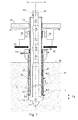
- Fig. 1 shows a wellbore 1 formed in an earth formation 2 whereby an expandable tubular element 4 extends into the wellbore.
- Reference sign 6 indicates the earth surface.
- the tubular element 4 includes an unexpanded tubular section 8 and a radially expanded tubular section 10 of outer diameter substantially equal to the diameter of the wellbore.
- the expanded tubular section serves to support the wellbore wall and to prevent undesired inflow of formation fluid into the wellbore 1, or to prevent undesired outflow of wellbore fluid into the formation 2.
- the expandable tubular element therefore also will be referred to as "liner”, the unexpanded tubular section will be referred to as “unexpanded liner section”, and the radially expanded tubular section will be referred to as “expanded liner section”.
- the unexpanded liner section 8 extends substantially concentrically within the expanded liner section 10.
- the unexpanded liner section 8 has an upper end located at a position in the wellbore 1 commensurate with the length and depth of the wellbore section that is to lined by eversion of the expandable tubular element 4.
- the lower end of the unexpanded liner section 8 is located a short distance above the wellbore bottom during drilling of the wellbore 1.
- the wall of the unexpanded liner section 8 bends radially outward and in axially reverse (in Fig. 1 upward) direction so as to form a curved lower section 12 defining a bending zone 14 of the tubular element 4.
- the curved lower section 12 is U-shaped and interconnects the unexpanded liner section 8 and the expanded liner section 10.
- the expanded liner section 10 and the unexpanded liner section 8 define an annular space 16 there between, which is closed at its lower end by the curved lower section 12 of the expandable tubular element 4.
- the annular space 16 is also referred to as the blind annulus.
- the unexpanded liner section 8 is at its outer surface provided with a plurality of metal strips 17, which will be described hereinafter in more detail.
- a drill string 18 extends from surface through the unexpanded liner section 8 to the bottom of the wellbore 1.
- the lower end of the drill string 18 is provided with a drill bit 20 comprising a pilot bit 22 of outer diameter slightly smaller than the inner diameter of the unexpanded liner section 8, and a reamer section 24 having an outer diameter adapted to drill the wellbore 1 to its nominal diameter.
- the reamer section 24 is radially retractable to a smaller outer diameter, allowing it to be lowered or retrieved through the unexpanded liner section 8.
- the drill string 18 may comprise multiple drill pipe sections 26 mutually interconnected by threaded connections 28.
- An annular space 30 is formed between the drill string 18 and the unexpanded liner section 8, said annular space 30 being referred to hereinafter as the drilling annulus 30.
- connections 28 are not shown in detail, but comprise for instance threaded pin and box type connections.
- the connections 28 may comprise joints fabricated with male threads on each end, wherein short-length coupling members (not shown) with female threads are used to join the individual joints of drill string together, or joints with male threads on one end and female threads on the other.
- the threaded connections may comprise connections which are standardized by the American Petroleum Institute (API).
- API American Petroleum Institute
- the drill string 18 and the unexpanded liner section 8 extend through an opening 32 of a rig floor 34 which is part of a drilling rig (not shown).
- a pipe pusher 36 is provided for moving the unexpanded liner section 8 in downward direction.
- the pipe pusher 36 is for instance arranged below the rig floor and is supported by a base frame 38 that is connected to the drilling rig or directly to surface 6.
- the pipe pusher may comprise one or more conveyor belts 40, whereby each conveyor belt engages the outer surface of the unexpanded liner section 8 and is driven by a respective motor (not shown).
- Each conveyer belt 40 is adapted to exert a downward force to the unexpanded liner section 8 so as to push the unexpanded liner section into the borehole.
- Other embodiments of the pipe pusher 36 capable of exerting a downward or upward force to the unexpanded liner section 8, are conceivable.
- a sealing device 42 is connected to the upper end of the expanded liner section 10 to seal the unexpanded liner section 8 relative to the expanded liner section 10.
- the sealing device 42 enables the unexpanded liner section 8 to slide in axial direction relative to the sealing device 42.
- the sealing device comprises a conduit 44 connected to a pump (not shown) for pumping fluid into or out of the blind annulus 16.
- the sealing device includes one, two or more annular seals 46 whereby each annular seal engages the outside of the unexpanded liner section 8 so as to prevent undesired outflow of fluid from the blind annulus.
- the sealing device 42 comprises at least two seals 46 for improved safety and reliability in case one of the seals fails.
- the sealing device 42 can be regarded as a blind annulus blow out preventer (BABOP). Therefore, the annular seals 46, the connection of the sealing device 42 to the upper end of the expanded liner section 10, and one or more valves (not shown) for closing conduit 44 are all designed to withstand fluid pressures that may arise in a well control situation.
- the sealing device 42 is for instance designed to withstand fluid pressures that may be expected in case of a blowout, for instance in the range of 200 bar to 1600 bar, for instance about 400 bar to 800 bar or more. Such pressures may arise in the blind annulus 16 in case of a failure, for instance due to rupturing of the expandable tubular element 4 during a well control situation.
- the expanded liner section 10 is axially fixed relative to the wellbore by any suitable fixation means.
- the upper end of the expanded liner section may be connected to a ring or flange (not shown) by welding and/or screwing.
- Said ring can be attached to or incorporated in any suitable structure at surface, such as the sealing device 42.
- the inner diameter of said ring may be larger than the outer diameter of the expanded liner section.
- the expanded liner section 10 may be fixed to the wellbore wall, for instance by virtue of frictional forces between the expanded liner section 10 and the wellbore wall as a result of the expansion process.
- the expanded liner section 10 can be anchored, for instance to the wellbore wall, by any suitable anchoring means.
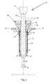
- Fig. 2 shows a top drive system 50 for optional use in combination with the system of Fig. 1 .
- the top drive system is adapted to be connected to the system of Fig. 1 at the common interface indicated by line 1-1 ( Fig. 1 ), and comprises a motor 52 and an upper connection part 54 driven by the motor.
- the upper connection part forms a flush pipe having a smooth outer surface and being connected at its lower end to an additional drill string section 56 by means of a threaded connection 28.
- the additional drill string section 56 is substantially similar to the drill string sections 26 shown in Fig. 1 .
- the additional drill string section 56 can be connected to the upper end of the drill string 18 shown in Fig. 1 .
- the top drive system 50 further comprises a drilling annulus sealing device 58 including a housing 60 that encloses the flush pipe 54, with an annular space 62 there between.
- the annular space 62 is in fluid communication with the drilling annulus 30.
- the housing 60 At the top end, near the top drive motor 52, the housing 60 comprises one, two or more seals 64 which engage the outside of the flush pipe 54.
- the seals 64 enable the housing to slide along the flush pipe 54.
- the top drive system comprises an additional pipe section 66 of substantially the same outer diameter and wall-thickness as the unexpanded liner section 8.
- the housing 60 may comprise one, two or more seals 68 which engage the outer surface of the additional pipe section 66.
- the housing may comprise grippers 70 that engage the outside and/or the inside of the additional pipe section 66.
- An activation conduit 72 is connected to the housing for activating or releasing the seals 68 and/or the grippers 70.
- a fluid conduit 74 is provided to the housing for supply or drainage of (drilling) fluid to or from the drilling annulus 30 via the annular space 62.
- the sealing device 58 comprises an extending part or stinger 76 that extends into the inside of the additional pipe section 66.
- the stinger may comprise seals 78 and/or grippers to engage the upper end of the pipe section 66.
- the stinger may also comprise seals 80 to engage a lower end of the pipe section 66, and seals 82 to engage the inside of the upper end of the unexpanded liner section 8.
- a backing gas tool (not shown) may be integrated in the stinger between the seals 80, 82 to cover the inner interface between the additional pipe section 66 and the unexpanded liner section 8.
- the stinger 76 is at least slightly longer than the pipe section 66 so that the stinger may extend into the unexpanded liner section 8 to enable the stinger to function as an alignment tool for aligning the pipe section 66 with the unexpanded liner section 8.
- the length of the pipe section 66 may be in the range of about 5-20 metres, for instance 10 metres.
- the stinger will for instance be about 2% to 10% longer, for instance 5% longer than the pipe section 66.
- the sealing device 58 may be referred to as drilling annulus blow out preventer (DABOP).
- DABOP drilling annulus blow out preventer
- the seals 64, 68, 78, 80, 82, the grippers 70, and one or more valves (not shown) for closing conduits 72, 74 are all designed to at least withstand fluid pressures that may arise in a well control situation.
- the DABOP 58 is for instance designed to withstand pressures in the range of about 200 bar to 800 bar or more, for instance about 400 bar.
- the DABOP may comprise any number of seals, for example one seal 64 and one seal 68, or a plurality of seals.
- two seals 64 that engage the flush pipe 66 and two seals 68 that engage the pipe section 66 will provide a balance between fail-safety and reliability on one hand and costs on the other hand.
- the double barrier provided by the inner seals 78 engaging the inside of the pipe section 66, and the outer seals 68 engaging the outside of the pipe section 66 improves the reliability and leaktightness of the sealing device 58.
- the diameter and/or wall thickness of the expandable tubular element 4 is selected such that the expanded liner section 10 is pressed against the wellbore wall during the eversion process.
- the expanded liner section 10 thereby seals against the wellbore wall and/or stabilizes the wellbore wall.
- the wall thickness of the expandable tubular element 4 may be equal to or larger than about 2 mm (0.08 inch), for example larger than 2.5 mm.
- the wall thickness is for instance about 3 to 30 mm or for instance about 2 to 10 mm.
- the outer diameter of the unexpanded liner section may be larger than 50 mm (2 inch), for instance in the range of about 50 to 400 mm (16 inch).
- the expanded liner section may have any outer diameter suitable for, or commonly used in, hydrocarbon production.
- the wall of the expandable tubular element 4 may comprise a relatively strong material, such as a metal, preferably steel. Thus, the expandable tubular element 4 can be designed to have adequate collapse strength to support the wellbore wall and/or to withstand internal or external pressures encountered when drilling for hydrocarbon reservoirs.
- the length and hence the weight of the unexpanded liner section 8 gradually increases during extension of the wellbore. Hence, the downward force exerted by the pipe pusher 36 can be gradually decreased in correspondence with the increasing weight. As said weight increases, the downward force eventually may need to be replaced by an upward force to maintain the total force within a predetermined range and to prevent buckling of the unexpanded liner section 8.
- Fig. 3 shows the unexpanded liner section 8 in more detail.
- the unexpanded liner section 8 may be made up of several pipe sections interconnected by circumferential welds.
- weld 90 interconnects first pipe section 92 and second pipe section 94.
- a number of metal strips 17 are provided at the outer surface of the unexpanded tubular section 8 to strengthen the weld 90.
- Each metal strip 17 is connected to the outer surface by, for example, brazing, welding or gluing. Each metal strip 17 extends in longitudinal direction across the weld 90 and has a resistance to stretching in said longitudinal direction.
- the metal strips 17 are of substantially equal length and are arranged in a staggered configuration (as shown in Fig. 3 ).
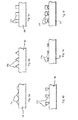
- FIGS. 4a-4f Examples of suitable cross-sectional shapes of the strengthening members 17 are shown in Figs. 4a-4f .
- reference sign 98 indicates the wall of the unexpanded tubular section 8
- the respective strengthening members are indicated by reference signs 17a, 17b, 17c, 17d, 17e, 17f.
- the strengthening members may be triangular, having either rounded ends as shown in Fig. 4a , or pointy ends as shown in Figs. 4b, 4d .
- the base of the triangles may face in either uphole or downhole direction.
- the strengthening members may be rectangular ( Fig. 4c ), for instance having the form of strips or being square or any rectangular form therein between.
- the strengthening members may be T-shaped or n-shaped, as shown in Figs. 4e, 4f .
- the strengthening members may have a shape and size to provide a predetermined bending stiffness.
- the bending stiffness is for instance equal to the product of the elastic modulus E and the area moment of inertia I of the strip cross-section about the axis of interest.
- the bending stiffness is EI .
- a ratio of the bending stiffness of the wall of the tubular element to the bending stiffness of the one or more strengthening members combined is for instance in the range of 1:6 to 1:10, for instance about 1:8.
- the strengthening members may have a length in the range of 5 to 30 cm, for instance about 15 cm long.
- the circumference of the unexpanded section may be provided with any number of strips, for instance about 5 to 50 strips in total.
- the strengthening members may be made of any suitable material to provide the above bending stiffness. Suitable materials include for instance metal, steel, and rubber-like materials.
- the most appropriate method to connect the strengthening members to the tubular element may depend on the size and shape of the strengthening members.
- a tubular element having an outer diameter of 6-5/8 inch may be provided with strips 17 of about 10 cm long, about 1 cm wide and about 1 mm thick. Substantially the entire inner surface (i.e. the surface facing the tubular element) of said strips may be provided with a brazing material. By heating to a temperature exceeding the melting temperature of the brazing material, the strips can be metallurgically bonded to the tubular element along their inner surface.
- the opposite ends of the strips 17 may be welded to the pipe 8, in addition to the brazing, to improve the bonding and to prevent said ends from peeling off during eversion of the pipe.
- connection methods or combinations of connection methods may be suitable, depending on for instance the size, shape and material of the strengthening members.
- Rubber-like materials or relatively thin strips e.g. in the order of 0.5 mm or less
- Relatively thick strengthening members e.g. in the order of 2 mm or more
- Fig. 5 shows the downhole portion of the tubular element during the eversion process.
- the weld 90 and the metal strips 17 are near but not yet in the bending zone 14 of the tubular element.
- Fig. 6 shows the downhole portion of the tubular element 4 during the eversion process, wherein the weld 90 and the metal strips 17 are in the bending zone 14 of the tubular element.
- the drill string 18 is operated to rotate the drill bit 20 to extend the borehole.
- the drill string is gradually lowered into the borehole.
- the pipe pusher 36 is operated to push the unexpanded liner section 8 into the borehole at a speed substantially twice the speed of downward movement of the drill string 18.
- the unexpanded liner section may be pushed downhole to extend the liner may during drilling, but may also be pushed subsequently in a separate step.
- the expanded liner section 10 remains stationary in the wellbore, and the unexpanded liner section 8 is gradually everted to extend the downhole end of the expanded liner section 10.
- the bending zone 14 moves in downward direction.
- the bending zone may move at substantially the same speed at which the drill string 18 is lowered into the wellbore. In this manner the distance between the bending zone 14 and the drill bit 20 can be kept relatively short, limiting the length L1 of the open hole section (see Fig. 1 ).
- the open hole section is the unlined section of the wellbore 1.
- the method of the present invention enables an open hole section of length L1 less than, for instance, 100 metres or even less than 50 metres at all times while drilling the borehole.
- the wall of the tubular element 4 is initially bent radially outward whereby the wall assumes a curved shape, and thereafter bent in reverse direction whereby the wall again assumes a straight shape (as shown in Figs. 5, 6 ). It was found that, prior to applying the metal strips in accordance with the invention, tensile stresses during reverse bending of the weld sometimes cause fracturing of the weld or fracturing of the wall in the heat-affected zone near the weld. This problem is overcome by virtue of the metal strips 17 which provide resistance to stretching at the inner surface of the weld 96 (i.e. the surface facing the blind annulus 16) during reverse bending of the weld.
- the bending stresses across the thickness of the wall vary substantially linearly from compressive to tensile, whereby a neutral line is defined by the points where the bending stresses vanish.
- a neutral line is defined by the points where the bending stresses vanish.
- the neutral line extends in in the middle of the wall.
- the metal strips 17 cause the neutral line during reverse bending to shift towards the metal strips, or even into the metal strips. It is thereby achieved that the tensile stresses in the weld 96 and in the heat affected zone around the weld, become less severe or totally vanish while the compressive stresses in the wall increase.
- the unexpanded liner section 8 may be supported by the drill string 18, for example by means of a bearing device (not shown) connected to the drill string, which supports the curved lower section 12 of the liner 4.
- a bearing device (not shown) connected to the drill string, which supports the curved lower section 12 of the liner 4.
- an upward force is suitably transmitted from the drill string 18 to the curved lower section 12 via the bearing device.
- at least part of the weight of the unexpanded liner section 8 and the pipe then can be transferred to the drill string and utilised to provide a thrust force to the drill bit 20.
- Drilling fluid containing drill cuttings is discharged from the drilling annulus 30 via fluid conduit 74.
- drilling fluid may be circulated in reverse circulation mode wherein the drilling fluid is pumped into the wellbore via the conduit 74 and discharged from the wellbore via the drill string 18.
- the reamer section 24 can be collapsed to its radially retracted mode whereby the diameter is smaller than the inner diameter of the unexpanded liner section 8. Subsequently, the drill string 18 can be retrieved through the unexpanded liner section 8 to surface.
- a remaining portion of the unexpanded liner section can be left in the wellbore or it can be retrieved to surface.
- expansion of the liner is started at surface or at a down hole location.
- the bending zone moves from the offshore platform to the seabed and subsequently into the wellbore.
- the resulting expanded tubular element not only forms a liner in the wellbore, but also a riser extending from the offshore platform to the seabed. The need for a separate riser is thereby obviated.
- conduits such as electric wires or optical fibres for communication with down hole equipment can be extended in the annulus between the expanded and unexpanded sections.
- Such conduits can be attached to the outer surface of the tubular element before expansion thereof.
- the expanded and unexpanded liner sections can be used as electricity conductors to transfer data and/or power down hole.
- a friction reducing layer such as a Teflon layer, may be applied between the unexpanded liner section and the expanded liner section to reduce friction forces during the eversion process.
- a friction reducing coating can be applied to the outer surface of the unexpanded liner section.
- the friction reducing layer reduces the width of the blind annulus, and thereby minimizes or eliminates a possible tendency of the unexpanded liner section to buckle.
- centralizing pads and/or rollers can be applied in the blind annulus between the unexpanded and expanded sections to reduce the friction and the annular clearance.
- the expanded liner section can be expanded against the inner surface of another tubular element, e.g. casing or a liner, already present in the wellbore.
- another tubular element e.g. casing or a liner
- the present invention is likewise suitable for use with alternative drilling systems.
- the latter may include for instance a down hole motor instead of a top drive.
- Said down hole motor is a drilling tool comprised in the drill string directly above the bit. Activated by pressurized drilling fluid, it causes the bit to turn while the drill string remains fixed.
- Examples of the down hole motor include a positive-displacement motor and a down hole turbine motor.
- the present invention is likewise suitable for directional drilling, i.e. drilling wherein the drilling direction can be adjusted.
- a down hole motor may be used as a deflection tool in directional drilling, where it is made up between the bit and a bent sub, or the housing of the motor itself may be bent.
- the metal strips are directly connected to the outer surface of the unexpanded liner section.
- the strips can be formed from a tubular metal layer fixedly connected to the outer surface of the unexpanded liner section, whereby longitudinal grooves are machined into the layer, and whereby each strip is defined between two such adjacent longitudinal grooves.
- the strips are made of a metal such as steel, the strips alternatively can be made of any other suitable material which provides the required resistance to stretching.
Landscapes
- Life Sciences & Earth Sciences (AREA)
- Engineering & Computer Science (AREA)
- Geology (AREA)
- Mining & Mineral Resources (AREA)
- Physics & Mathematics (AREA)
- Environmental & Geological Engineering (AREA)
- Fluid Mechanics (AREA)
- General Life Sciences & Earth Sciences (AREA)
- Geochemistry & Mineralogy (AREA)
- Earth Drilling (AREA)
Abstract
A system is disclosed for lining a borehole. The system comprises a radially expandable tubular element extending into the borehole. The wall of the tubular element at a downhole end thereof is bent radially outward and in axially reverse direction so as to define an expanded tubular section extending around an unexpanded tubular section. The unexpanded tubular section includes a weld interconnecting first and second wall portions of the wall. An actuator is arranged to move the unexpanded tubular section downward relative to the expanded tubular section so as to further expand the tubular element by bending the wall of the tubular element at the lower end thereof radially outward and in axially reverse direction. At least one strengthening member is arranged at the outer surface of the unexpanded tubular section, extending in a direction across the weld. Each strengthening member has a resistance to stretching in said direction across the weld.
Description
- The present invention relates to a system for radially expanding a tubular element in a borehole formed in an earth formation.
- The technology of radially expanding tubular elements finds increasing application in the industry of oil and gas production from subterranean formations. Wellbores are generally provided with one or more casings or liners to provide stability to the wellbore wall, and/or to provide zonal isolation between different earth formation layers. The terms "casing" and "liner" refer to tubular elements for supporting and stabilising the wellbore wall. Typically, a casing extends from surface into the wellbore and a liner extends from a certain depth further into the wellbore. However, in the present context, the terms "casing" and "liner" are used interchangeably and without such intended distinction.
- In conventional wellbore construction several casings are set at depth intervals, in a nested arrangement. Herein, each subsequent casing is lowered through the previous casing and therefore must have a smaller diameter than the previous casing. As a result, the cross-sectional area of the wellbore that is available for oil and gas production decreases with depth.
- To alleviate this drawback, it is possible to radially expand one or more tubular elements at a desired depth in the wellbore, for example to form an expanded casing, expanded liner, or a clad against an existing casing or liner. Also, it has been proposed to radially expand each subsequent casing to substantially the same diameter as the previous casing to form a monodiameter wellbore. It is thus achieved that the available diameter of the wellbore remains substantially constant along (a section of) its depth as opposed to the conventional nested arrangement.
-
WO-2008/006841 discloses a wellbore system for radially expanding a tubular element in a wellbore. The wall of the tubular element is induced to bend radially outward and in axially reverse direction so as to form an expanded section extending around an unexpanded section of the tubular element. The length of the expanded tubular section is increased by moving, for instance by forcing or pushing, the unexpanded section into the expanded section. Herein the expanded section retains the expanded tubular shape. At its top end, the unexpanded section can, for instance, be extended by adding pipe sections or by unreeling, folding and welding a sheet of material into a tubular shape. - It was found that, for applications whereby the tubular element is formed of welded pipe sections, damage may occur to the tubular element when the welds are bended in reverse direction during the eversion process.
- The present invention aims to provide an improved system for expanding a tubular element in a borehole, which overcomes the problem of the prior art.
- The invention therefore provides a system for lining a borehole formed in an earth formation, the system comprising:
- a radially expandable tubular element extending into the borehole, wherein the wall of the tubular element at a downhole end thereof is bent radially outward and in axially reverse direction to define an expanded tubular section extending around an unexpanded tubular section of the tubular element, and wherein the unexpanded tubular section includes a weld interconnecting a first wall portion and a second wall portion;
- an actuator arranged to move the unexpanded tubular section downward relative to the expanded tubular section so as to further expand the tubular element by bending the wall of the tubular element at the lower end thereof radially outward and in axially reverse direction; and
- at least one strengthening member arranged at the outer surface of the unexpanded tubular section and extending in a direction across the weld, each strengthening member having a resistance to stretching in said direction across the weld.
- During reverse bending of the wall of the tubular element, the bending stresses across the thickness of the wall vary substantially linearly from compressive to tensile, whereby a neutral line is defined by the points where the bending stresses vanish. By virtue of each strengthening member it is achieved that the neutral line during reverse bending is shifted towards the strengthening member. The tensile stresses in the weld, or in the heat affected zone around the weld, are thereby limited or totally vanish while the compressive stresses increase. Failure of the weld or the wall of the tubular near the weld during bending may thus be obviated in an efficient and cost effective way.
- In case the weld extends substantially in circumferential direction of the tubular element, each strengthening member suitably extends substantially in longitudinal direction of the tubular element. However the system of the present invention is equally suitable for applications whereby the weld extends in any other direction, for example whereby the weld extend at an angle to the axial direction or even whereby the weld extends in axial direction. In each such application , it is preferred that the strengthening member(s) extend(s) substantially transverse to the weld.
- Preferably said at least one strengthening member comprises a plurality of strengthening members regularly spaced along the circumference of the unexpanded tubular section.
- To adequately distribute the forces required to bend the wall of the tubular element, suitably the strengthening members are arranged staggered in longitudinal direction of the tubular element.
- Each strengthening member can be formed, for example, as an elongate strip or a patch. Furthermore, each strengthen member is suitably connected to said first and second wall portions by brazing, welding or gluing.
- The system of the invention is most advantageously applied during drilling of the borehole, whereby a drill string extends through the unexpanded tubular section for further drilling of the wellbore. In this manner a short open-hole section can be maintained throughout the drilling operation, so that there is a reduced risk of fracturing the formation due to drilling fluid pressure being too high and also a reduced risk of undesired formation fluid inflow into the wellbore due to drilling fluid pressure being too low. In order to maintain an open-hole section of substantially constant length, suitably the actuator is adapted to move the unexpanded tubular section axially downward at a speed substantially twice the speed of lowering the drill string into the borehole during further drilling of the borehole with the drill string.
- The invention will be described hereinafter in more detail and by way of example, with reference to the accompanying drawings in which:
-
Fig. 1 shows a longitudinal section of an embodiment of a system for expanding a tubular element in a borehole in accordance with the invention; -
Fig. 2 schematically shows an optional top drive system for use in combination with the embodiment ofFig. 1 ; -
Fig. 3 schematically shows a portion of an unexpanded section of the tubular element; -
Figs. 4a-f schematically show various examples of strengthening members used in the system of the invention; -
Fig. 5 schematically shows the portion ofFig. 3 prior to eversion of a weld; and -
Fig. 6 schematically shows the portion ofFig. 3 during eversion of the weld. - In the drawings and the description, like reference numerals relate to like components.
-
Fig. 1 shows awellbore 1 formed in an earth formation 2 whereby an expandabletubular element 4 extends into the wellbore. Reference sign 6 indicates the earth surface. Thetubular element 4 includes an unexpandedtubular section 8 and a radially expandedtubular section 10 of outer diameter substantially equal to the diameter of the wellbore. The expanded tubular section serves to support the wellbore wall and to prevent undesired inflow of formation fluid into thewellbore 1, or to prevent undesired outflow of wellbore fluid into the formation 2. The expandable tubular element therefore also will be referred to as "liner", the unexpanded tubular section will be referred to as "unexpanded liner section", and the radially expanded tubular section will be referred to as "expanded liner section". Theunexpanded liner section 8 extends substantially concentrically within the expandedliner section 10. - Although the borehole shown in
Figure 1 extends vertically into the earth formation 2, the present invention is equally suitable for any other borehole. For instance, theborehole 1 may extend inclined or at least partially horizontally. Therefore, in this description, references to "upper" and "lower" in relation to the wellbore are intended to refer to borehole positions measured along the longitudinal axis of the borehole. - The
unexpanded liner section 8 has an upper end located at a position in thewellbore 1 commensurate with the length and depth of the wellbore section that is to lined by eversion of the expandabletubular element 4. The lower end of theunexpanded liner section 8 is located a short distance above the wellbore bottom during drilling of thewellbore 1. At said lower end, the wall of theunexpanded liner section 8 bends radially outward and in axially reverse (inFig. 1 upward) direction so as to form a curvedlower section 12 defining abending zone 14 of thetubular element 4. The curvedlower section 12 is U-shaped and interconnects theunexpanded liner section 8 and the expandedliner section 10. The expandedliner section 10 and theunexpanded liner section 8 define anannular space 16 there between, which is closed at its lower end by the curvedlower section 12 of the expandabletubular element 4. Theannular space 16 is also referred to as the blind annulus. - The
unexpanded liner section 8 is at its outer surface provided with a plurality ofmetal strips 17, which will be described hereinafter in more detail. - A
drill string 18 extends from surface through theunexpanded liner section 8 to the bottom of thewellbore 1. The lower end of thedrill string 18 is provided with adrill bit 20 comprising apilot bit 22 of outer diameter slightly smaller than the inner diameter of theunexpanded liner section 8, and areamer section 24 having an outer diameter adapted to drill thewellbore 1 to its nominal diameter. Thereamer section 24 is radially retractable to a smaller outer diameter, allowing it to be lowered or retrieved through theunexpanded liner section 8. Thedrill string 18 may comprise multipledrill pipe sections 26 mutually interconnected by threadedconnections 28. Anannular space 30 is formed between thedrill string 18 and theunexpanded liner section 8, saidannular space 30 being referred to hereinafter as thedrilling annulus 30. - The
connections 28 are not shown in detail, but comprise for instance threaded pin and box type connections. Theconnections 28 may comprise joints fabricated with male threads on each end, wherein short-length coupling members (not shown) with female threads are used to join the individual joints of drill string together, or joints with male threads on one end and female threads on the other. The threaded connections may comprise connections which are standardized by the American Petroleum Institute (API). Thedrill string 18 and theunexpanded liner section 8 extend through anopening 32 of arig floor 34 which is part of a drilling rig (not shown). - A
pipe pusher 36 is provided for moving theunexpanded liner section 8 in downward direction. Thepipe pusher 36 is for instance arranged below the rig floor and is supported by abase frame 38 that is connected to the drilling rig or directly to surface 6. The pipe pusher may comprise one ormore conveyor belts 40, whereby each conveyor belt engages the outer surface of theunexpanded liner section 8 and is driven by a respective motor (not shown). Eachconveyer belt 40 is adapted to exert a downward force to theunexpanded liner section 8 so as to push the unexpanded liner section into the borehole. Other embodiments of thepipe pusher 36 capable of exerting a downward or upward force to theunexpanded liner section 8, are conceivable. - A sealing
device 42 is connected to the upper end of the expandedliner section 10 to seal theunexpanded liner section 8 relative to the expandedliner section 10. Herein, the sealingdevice 42 enables theunexpanded liner section 8 to slide in axial direction relative to the sealingdevice 42. The sealing device comprises aconduit 44 connected to a pump (not shown) for pumping fluid into or out of theblind annulus 16. The sealing device includes one, two or moreannular seals 46 whereby each annular seal engages the outside of theunexpanded liner section 8 so as to prevent undesired outflow of fluid from the blind annulus. Preferably the sealingdevice 42 comprises at least twoseals 46 for improved safety and reliability in case one of the seals fails. - The sealing
device 42 can be regarded as a blind annulus blow out preventer (BABOP). Therefore, theannular seals 46, the connection of the sealingdevice 42 to the upper end of the expandedliner section 10, and one or more valves (not shown) for closingconduit 44 are all designed to withstand fluid pressures that may arise in a well control situation. Depending on specifics of the formation, the sealingdevice 42 is for instance designed to withstand fluid pressures that may be expected in case of a blowout, for instance in the range of 200 bar to 1600 bar, for instance about 400 bar to 800 bar or more. Such pressures may arise in theblind annulus 16 in case of a failure, for instance due to rupturing of the expandabletubular element 4 during a well control situation. - The expanded
liner section 10 is axially fixed relative to the wellbore by any suitable fixation means. For instance, the upper end of the expanded liner section may be connected to a ring or flange (not shown) by welding and/or screwing. Said ring can be attached to or incorporated in any suitable structure at surface, such as the sealingdevice 42. The inner diameter of said ring may be larger than the outer diameter of the expanded liner section. Optionally, the expandedliner section 10 may be fixed to the wellbore wall, for instance by virtue of frictional forces between the expandedliner section 10 and the wellbore wall as a result of the expansion process. Alternatively, or additionally, the expandedliner section 10 can be anchored, for instance to the wellbore wall, by any suitable anchoring means. -
Fig. 2 shows atop drive system 50 for optional use in combination with the system ofFig. 1 . The top drive system is adapted to be connected to the system ofFig. 1 at the common interface indicated by line 1-1 (Fig. 1 ), and comprises amotor 52 and anupper connection part 54 driven by the motor. In the present example, the upper connection part forms a flush pipe having a smooth outer surface and being connected at its lower end to an additionaldrill string section 56 by means of a threadedconnection 28. Typically, the additionaldrill string section 56 is substantially similar to thedrill string sections 26 shown inFig. 1 . At the interface indicated by line 1-1, the additionaldrill string section 56 can be connected to the upper end of thedrill string 18 shown inFig. 1 . - The
top drive system 50 further comprises a drillingannulus sealing device 58 including ahousing 60 that encloses theflush pipe 54, with anannular space 62 there between. Theannular space 62 is in fluid communication with thedrilling annulus 30. At the top end, near thetop drive motor 52, thehousing 60 comprises one, two ormore seals 64 which engage the outside of theflush pipe 54. Theseals 64 enable the housing to slide along theflush pipe 54. Furthermore, the top drive system comprises anadditional pipe section 66 of substantially the same outer diameter and wall-thickness as theunexpanded liner section 8. Thehousing 60 may comprise one, two ormore seals 68 which engage the outer surface of theadditional pipe section 66. Also, the housing may comprisegrippers 70 that engage the outside and/or the inside of theadditional pipe section 66. Anactivation conduit 72 is connected to the housing for activating or releasing theseals 68 and/or thegrippers 70. Afluid conduit 74 is provided to the housing for supply or drainage of (drilling) fluid to or from thedrilling annulus 30 via theannular space 62. - The sealing
device 58 comprises an extending part orstinger 76 that extends into the inside of theadditional pipe section 66. The stinger may compriseseals 78 and/or grippers to engage the upper end of thepipe section 66. The stinger may also compriseseals 80 to engage a lower end of thepipe section 66, and seals 82 to engage the inside of the upper end of theunexpanded liner section 8. A backing gas tool (not shown) may be integrated in the stinger between theseals additional pipe section 66 and theunexpanded liner section 8. Thestinger 76 is at least slightly longer than thepipe section 66 so that the stinger may extend into theunexpanded liner section 8 to enable the stinger to function as an alignment tool for aligning thepipe section 66 with theunexpanded liner section 8. In practice, the length of thepipe section 66 may be in the range of about 5-20 metres, forinstance 10 metres. The stinger will for instance be about 2% to 10% longer, for instance 5% longer than thepipe section 66. - The sealing
device 58 may be referred to as drilling annulus blow out preventer (DABOP). Theseals grippers 70, and one or more valves (not shown) for closingconduits DABOP 58 is for instance designed to withstand pressures in the range of about 200 bar to 800 bar or more, for instance about 400 bar. - The DABOP may comprise any number of seals, for example one
seal 64 and oneseal 68, or a plurality of seals. In a practical embodiment, twoseals 64 that engage theflush pipe 66 and twoseals 68 that engage thepipe section 66 will provide a balance between fail-safety and reliability on one hand and costs on the other hand. For instance, the double barrier provided by theinner seals 78 engaging the inside of thepipe section 66, and theouter seals 68 engaging the outside of thepipe section 66, improves the reliability and leaktightness of the sealingdevice 58. - In a practical embodiment, the diameter and/or wall thickness of the expandable
tubular element 4 is selected such that the expandedliner section 10 is pressed against the wellbore wall during the eversion process. The expandedliner section 10 thereby seals against the wellbore wall and/or stabilizes the wellbore wall. - The wall thickness of the expandable
tubular element 4 may be equal to or larger than about 2 mm (0.08 inch), for example larger than 2.5 mm. The wall thickness is for instance about 3 to 30 mm or for instance about 2 to 10 mm. The outer diameter of the unexpanded liner section may be larger than 50 mm (2 inch), for instance in the range of about 50 to 400 mm (16 inch). The expanded liner section may have any outer diameter suitable for, or commonly used in, hydrocarbon production. The wall of the expandabletubular element 4 may comprise a relatively strong material, such as a metal, preferably steel. Thus, the expandabletubular element 4 can be designed to have adequate collapse strength to support the wellbore wall and/or to withstand internal or external pressures encountered when drilling for hydrocarbon reservoirs. - The length and hence the weight of the
unexpanded liner section 8 gradually increases during extension of the wellbore. Hence, the downward force exerted by thepipe pusher 36 can be gradually decreased in correspondence with the increasing weight. As said weight increases, the downward force eventually may need to be replaced by an upward force to maintain the total force within a predetermined range and to prevent buckling of theunexpanded liner section 8. -
Fig. 3 shows theunexpanded liner section 8 in more detail. Theunexpanded liner section 8 may be made up of several pipe sections interconnected by circumferential welds. For example,weld 90 interconnectsfirst pipe section 92 andsecond pipe section 94. A number ofmetal strips 17 are provided at the outer surface of the unexpandedtubular section 8 to strengthen theweld 90. - Each
metal strip 17 is connected to the outer surface by, for example, brazing, welding or gluing. Eachmetal strip 17 extends in longitudinal direction across theweld 90 and has a resistance to stretching in said longitudinal direction. The metal strips 17 are of substantially equal length and are arranged in a staggered configuration (as shown inFig. 3 ). - Examples of suitable cross-sectional shapes of the strengthening
members 17 are shown inFigs. 4a-4f . In each of these figures referencesign 98 indicates the wall of the unexpandedtubular section 8, and the respective strengthening members are indicated byreference signs Fig. 4a , or pointy ends as shown inFigs. 4b, 4d . The base of the triangles may face in either uphole or downhole direction. Alternatively, the strengthening members may be rectangular (Fig. 4c ), for instance having the form of strips or being square or any rectangular form therein between. The strengthening members may be T-shaped or n-shaped, as shown inFigs. 4e, 4f . - The strengthening members may have a shape and size to provide a predetermined bending stiffness. In case the strengthening members have a longitudinal shape, the bending stiffness is for instance equal to the product of the elastic modulus E and the area moment of inertia I of the strip cross-section about the axis of interest. In other words, the bending stiffness is EI. According to elementary beam theory, the relationship between the applied bending moment M and the resulting curvature k of the beam is:

where w is the deflection of the strip and x the coordinate along the length of the strip. - In a practical embodiment, a ratio of the bending stiffness of the wall of the tubular element to the bending stiffness of the one or more strengthening members combined is for instance in the range of 1:6 to 1:10, for instance about 1:8.
- In a practical embodiment, the strengthening members may have a length in the range of 5 to 30 cm, for instance about 15 cm long. The circumference of the unexpanded section may be provided with any number of strips, for instance about 5 to 50 strips in total.
- The strengthening members may be made of any suitable material to provide the above bending stiffness. Suitable materials include for instance metal, steel, and rubber-like materials.
- The most appropriate method to connect the strengthening members to the tubular element may depend on the size and shape of the strengthening members.
- For instance, a tubular element having an outer diameter of 6-5/8 inch may be provided with
strips 17 of about 10 cm long, about 1 cm wide and about 1 mm thick. Substantially the entire inner surface (i.e. the surface facing the tubular element) of said strips may be provided with a brazing material. By heating to a temperature exceeding the melting temperature of the brazing material, the strips can be metallurgically bonded to the tubular element along their inner surface. Optionally, the opposite ends of thestrips 17 may be welded to thepipe 8, in addition to the brazing, to improve the bonding and to prevent said ends from peeling off during eversion of the pipe. - Alternative connection methods or combinations of connection methods may be suitable, depending on for instance the size, shape and material of the strengthening members. Rubber-like materials or relatively thin strips (e.g. in the order of 0.5 mm or less) may for instance be glued. Relatively thick strengthening members (e.g. in the order of 2 mm or more) may for instance be welded.
-
Fig. 5 shows the downhole portion of the tubular element during the eversion process. Herein, theweld 90 and the metal strips 17 are near but not yet in the bendingzone 14 of the tubular element. -
Fig. 6 shows the downhole portion of thetubular element 4 during the eversion process, wherein theweld 90 and the metal strips 17 are in the bendingzone 14 of the tubular element. - Operation of the embodiment described above, with the optional top drive system included, will be described hereinafter.
- The
drill string 18 is operated to rotate thedrill bit 20 to extend the borehole. Herein, the drill string is gradually lowered into the borehole. Thepipe pusher 36 is operated to push theunexpanded liner section 8 into the borehole at a speed substantially twice the speed of downward movement of thedrill string 18. The unexpanded liner section may be pushed downhole to extend the liner may during drilling, but may also be pushed subsequently in a separate step. - The expanded
liner section 10 remains stationary in the wellbore, and theunexpanded liner section 8 is gradually everted to extend the downhole end of the expandedliner section 10. During the eversion process, the bendingzone 14 moves in downward direction. The bending zone may move at substantially the same speed at which thedrill string 18 is lowered into the wellbore. In this manner the distance between the bendingzone 14 and thedrill bit 20 can be kept relatively short, limiting the length L1 of the open hole section (seeFig. 1 ). The open hole section is the unlined section of thewellbore 1. The method of the present invention enables an open hole section of length L1 less than, for instance, 100 metres or even less than 50 metres at all times while drilling the borehole. - In the bending
zone 14, the wall of thetubular element 4 is initially bent radially outward whereby the wall assumes a curved shape, and thereafter bent in reverse direction whereby the wall again assumes a straight shape (as shown inFigs. 5, 6 ). It was found that, prior to applying the metal strips in accordance with the invention, tensile stresses during reverse bending of the weld sometimes cause fracturing of the weld or fracturing of the wall in the heat-affected zone near the weld. This problem is overcome by virtue of the metal strips 17 which provide resistance to stretching at the inner surface of the weld 96 (i.e. the surface facing the blind annulus 16) during reverse bending of the weld. During reverse bending, the bending stresses across the thickness of the wall vary substantially linearly from compressive to tensile, whereby a neutral line is defined by the points where the bending stresses vanish. For example, in a wall of homogeneous material, the neutral line extends in in the middle of the wall. The metal strips 17 cause the neutral line during reverse bending to shift towards the metal strips, or even into the metal strips. It is thereby achieved that the tensile stresses in the weld 96 and in the heat affected zone around the weld, become less severe or totally vanish while the compressive stresses in the wall increase. - The
unexpanded liner section 8 may be supported by thedrill string 18, for example by means of a bearing device (not shown) connected to the drill string, which supports the curvedlower section 12 of theliner 4. In such application, an upward force is suitably transmitted from thedrill string 18 to the curvedlower section 12 via the bearing device. Furthermore, at least part of the weight of theunexpanded liner section 8 and the pipe then can be transferred to the drill string and utilised to provide a thrust force to thedrill bit 20. - Drilling fluid containing drill cuttings is discharged from the
drilling annulus 30 viafluid conduit 74. Alternatively, drilling fluid may be circulated in reverse circulation mode wherein the drilling fluid is pumped into the wellbore via theconduit 74 and discharged from the wellbore via thedrill string 18. - When it is required to retrieve the
drill string 18 to surface, for example when thedrill bit 20 is to be replaced or when drilling of thewellbore 1 has been completed, thereamer section 24 can be collapsed to its radially retracted mode whereby the diameter is smaller than the inner diameter of theunexpanded liner section 8. Subsequently, thedrill string 18 can be retrieved through theunexpanded liner section 8 to surface. - With the wellbore system of the invention, it is achieved that the wellbore is progressively lined with the everted liner directly above the drill bit, during the drilling process. As a result, there is only a relatively short open-hole section L1 of the wellbore during the drilling process at all times. An important advantage of a short open hole section is the reduced risk of influx of formation fluid into the wellbore during drilling. This eliminates or minimizes undesired increases of fluid pressure in the wellbore and simplifies well control. The advantages of such short open-hole section will be most pronounced during drilling into a hydrocarbon fluid containing layer of the earth formation. In view thereof, for many applications it will be sufficient if the process of liner eversion during drilling is applied only during drilling into the hydrocarbon fluid reservoir, while other sections of the wellbore are lined or cased in conventional manner. Alternatively, the process of liner eversion during drilling may be commenced at surface or at a selected down hole location, depending on circumstances.
- In view of the short open-hole section during drilling, there is a significantly reduced risk that the wellbore fluid pressure gradient exceeds the fracture gradient of the rock formation, or that the wellbore fluid pressure gradient drops below the pore pressure gradient of the rock formation. Therefore, considerably longer intervals can be drilled at a single nominal diameter than in a conventional drilling practice wherein casings of stepwise decreasing diameter must be set at selected intervals. Also, if the wellbore is drilled through a shale layer, such short open-hole section eliminates possible problems due to a heaving tendency of the shale.
- After the wellbore has been drilled to the desired depth and the drill string has been removed from the wellbore, a remaining portion of the unexpanded liner section can be left in the wellbore or it can be retrieved to surface.
- In case such remaining portion is left in the wellbore, there are several options for completing the wellbore. These are, for example, as outlined below.
- A) A fluid, for example brine, is pumped into the blind annulus so as to pressurise the blind annulus and increase the collapse resistance of the expanded liner section. Optionally one or more holes are provided in the U-shaped lower section to allow the pumped fluid to be circulated.
- B) A heavy fluid is pumped into the blind annulus so as to support the expanded liner section and increase its collapse resistance.
- C) Cement is pumped into the blind annulus in order to create a solid body between the pipe and the expanded liner section. The cement may expand upon hardening.
- D) The remaining portion of the unexpanded liner section is radially expanded (i.e. clad) against the expanded liner section, for example by pumping, pushing or pulling an expander through the remaining portion.
- In the above examples, expansion of the liner is started at surface or at a down hole location. In case of an offshore wellbore wherein an offshore platform is positioned above the wellbore, it may be advantageous to start the expansion process at the offshore platform, at or above the water surface. Herein, the bending zone moves from the offshore platform to the seabed and subsequently into the wellbore. Thus, the resulting expanded tubular element not only forms a liner in the wellbore, but also a riser extending from the offshore platform to the seabed. The need for a separate riser is thereby obviated.
- Furthermore, conduits such as electric wires or optical fibres for communication with down hole equipment can be extended in the annulus between the expanded and unexpanded sections. Such conduits can be attached to the outer surface of the tubular element before expansion thereof. Also, the expanded and unexpanded liner sections can be used as electricity conductors to transfer data and/or power down hole.
- A friction reducing layer, such as a Teflon layer, may be applied between the unexpanded liner section and the expanded liner section to reduce friction forces during the eversion process. For example, a friction reducing coating can be applied to the outer surface of the unexpanded liner section. Also, the friction reducing layer reduces the width of the blind annulus, and thereby minimizes or eliminates a possible tendency of the unexpanded liner section to buckle. Instead of, or in addition to, the friction reducing layer, centralizing pads and/or rollers can be applied in the blind annulus between the unexpanded and expanded sections to reduce the friction and the annular clearance.
- Instead of expanding the expanded liner section against the wellbore wall (as described), the expanded liner section can be expanded against the inner surface of another tubular element, e.g. casing or a liner, already present in the wellbore.
- Although the embodiments of the invention have been described including a top drive, the present invention is likewise suitable for use with alternative drilling systems. The latter may include for instance a down hole motor instead of a top drive. Said down hole motor is a drilling tool comprised in the drill string directly above the bit. Activated by pressurized drilling fluid, it causes the bit to turn while the drill string remains fixed. Examples of the down hole motor include a positive-displacement motor and a down hole turbine motor.
- The present invention is likewise suitable for directional drilling, i.e. drilling wherein the drilling direction can be adjusted. For instance, a down hole motor may be used as a deflection tool in directional drilling, where it is made up between the bit and a bent sub, or the housing of the motor itself may be bent.
- The present invention is not limited to the above-described embodiments thereof, wherein various modifications are conceivable within the scope of the appended claims. For instance, features of respective embodiments may be combined.
- In the example described above, the metal strips are directly connected to the outer surface of the unexpanded liner section. However, suitable alternative embodiments are conceivable. For example, the strips can be formed from a tubular metal layer fixedly connected to the outer surface of the unexpanded liner section, whereby longitudinal grooves are machined into the layer, and whereby each strip is defined between two such adjacent longitudinal grooves.
- Furthermore, instead of the strips being made of a metal such as steel, the strips alternatively can be made of any other suitable material which provides the required resistance to stretching.
- The present invention is not limited to the embodiments as described above, wherein various modifications are conceivable within the scope of the appended claims. Features of respective embodiments may for instance be combined.
Claims (14)
- A system for radially expanding a tubular element, the system comprising:- a radially expandable tubular element, wherein the wall of the tubular element at an end thereof is bent radially outward and in axially reverse direction to define an expanded tubular section extending around an unexpanded tubular section of the tubular element, and wherein the wall of the tubular element includes a weld interconnecting first and second wall portions;- an actuator arranged to move the unexpanded tubular section relative to the expanded tubular section to further expand the tubular element by bending the wall of the tubular element at the end thereof radially outward and in axially reverse direction; and- at least one strengthening member arranged at the outer surface of the unexpanded tubular section and extending across the weld, each strengthening member having a resistance to stretching.
- The system of claim 1, wherein each strengthening member extends substantially transverse to the weld
- The system of claim 1 or 2, wherein the weld extends substantially in circumferential direction of the tubular element, and wherein each strengthening member extends substantially in longitudinal direction of the tubular element.
- The system of claim 3, wherein said at least one strengthening member comprises a plurality of strengthening members regularly spaced along the circumference of the unexpanded tubular section.
- The system of claim 4, wherein the strengthening members are arranged staggered in longitudinal direction of the tubular element.
- The system of claim 4 or 5, wherein one strengthening member is displaced in axial direction of the tubular element with respect to one or more adjacent strengthening members.
- The system of any one of claims 1-6, wherein each strengthening member is selected from an elongate strip and a patch.
- The system of any one of claims 1-7, wherein each strengthening member is connected to said first wall portion and to said second wall portion by brazing, welding or gluing.
- The system of any one of claims 1-8, further comprising a drill string extending through the unexpanded tubular section for further drilling of the wellbore.
- The system of any of claims 1-9, wherein the actuator is adapted to push the unexpanded tubular section into the expanded section.
- The system of any one of claims 1-10,
wherein the tubular element is at least partially located within a borehole, and
wherein the expanded tubular section is compressed against the borehole wall or against another tubular element arranged in the borehole. - The system of any of claims 1-11, wherein a ratio of the bending stiffness of the wall of the tubular element to the bending stiffness of the one or more strengthening members combined is in the range of 1:6 to 1:10.
- The system of any of claims 1-12, wherein the strengthening members may have a length in the range of 5 to 30 cm.
- The system of any of claims 1-13, wherein the weld may be provided with about 5 to 50 strengthening members in total.
Priority Applications (1)
| Application Number | Priority Date | Filing Date | Title |
|---|---|---|---|
| EP12190414.8A EP2725278A1 (en) | 2012-10-29 | 2012-10-29 | System for expanding a tubular element in a borehole |
Applications Claiming Priority (1)
| Application Number | Priority Date | Filing Date | Title |
|---|---|---|---|
| EP12190414.8A EP2725278A1 (en) | 2012-10-29 | 2012-10-29 | System for expanding a tubular element in a borehole |
Publications (1)
| Publication Number | Publication Date |
|---|---|
| EP2725278A1 true EP2725278A1 (en) | 2014-04-30 |
Family
ID=47216076
Family Applications (1)
| Application Number | Title | Priority Date | Filing Date |
|---|---|---|---|
| EP12190414.8A Withdrawn EP2725278A1 (en) | 2012-10-29 | 2012-10-29 | System for expanding a tubular element in a borehole |
Country Status (1)
| Country | Link |
|---|---|
| EP (1) | EP2725278A1 (en) |
Citations (4)
| Publication number | Priority date | Publication date | Assignee | Title |
|---|---|---|---|---|
| US6254709B1 (en) * | 1998-10-26 | 2001-07-03 | Shonan Gosei-Jushi Seisakusho K.K. | Method of manufacturing a pipe liner bag |
| WO2008006841A1 (en) | 2006-07-13 | 2008-01-17 | Shell Internationale Research Maatschappij B.V. | Method of radially expanding a tubular element |
| WO2009056514A1 (en) * | 2007-10-29 | 2009-05-07 | Shell Internationale Research Maatschappij B.V. | Method of radially expanding a tubular element |
| EP2460972A1 (en) * | 2010-12-03 | 2012-06-06 | Shell Internationale Research Maatschappij B.V. | Method and system for radially expanding a tubular element |
-
2012
- 2012-10-29 EP EP12190414.8A patent/EP2725278A1/en not_active Withdrawn
Patent Citations (4)
| Publication number | Priority date | Publication date | Assignee | Title |
|---|---|---|---|---|
| US6254709B1 (en) * | 1998-10-26 | 2001-07-03 | Shonan Gosei-Jushi Seisakusho K.K. | Method of manufacturing a pipe liner bag |
| WO2008006841A1 (en) | 2006-07-13 | 2008-01-17 | Shell Internationale Research Maatschappij B.V. | Method of radially expanding a tubular element |
| WO2009056514A1 (en) * | 2007-10-29 | 2009-05-07 | Shell Internationale Research Maatschappij B.V. | Method of radially expanding a tubular element |
| EP2460972A1 (en) * | 2010-12-03 | 2012-06-06 | Shell Internationale Research Maatschappij B.V. | Method and system for radially expanding a tubular element |
Similar Documents
| Publication | Publication Date | Title |
|---|---|---|
| US9482070B2 (en) | Method and system for sealing an annulus enclosing a tubular element | |
| CN103334722B (en) | The method making tubular part expanded radially | |
| AU2008334603B2 (en) | Wellbore system | |
| CA2702870C (en) | Method of radially expanding a tubular element | |
| US20130213669A1 (en) | System and method for raially expanding a tubular element | |
| EP3034778A1 (en) | System and method for expanding a tubular element | |
| US9464481B2 (en) | Method and system for radially expanding a tubular element and directional drilling | |
| AU2013258158B2 (en) | Method and system for sealing an annulus enclosing a tubular element | |
| AU2011101766A4 (en) | System and method for radially expanding a tubular element comprising an emergency blow-out preventer | |
| CN101883909B (en) | Method of radially expanding a tubular element | |
| US20120138314A1 (en) | Method and system for radially expanding a tubular element | |
| EP2460972A1 (en) | Method and system for radially expanding a tubular element | |
| US9695676B2 (en) | System and method for lining a borehole | |
| EP3034777A1 (en) | System and method for expanding a tubular element with swellable coating |
Legal Events
| Date | Code | Title | Description |
|---|---|---|---|
| PUAI | Public reference made under article 153(3) epc to a published international application that has entered the european phase |
Free format text: ORIGINAL CODE: 0009012 |
|
| 17P | Request for examination filed |
Effective date: 20121029 |
|
| AK | Designated contracting states |
Kind code of ref document: A1 Designated state(s): AL AT BE BG CH CY CZ DE DK EE ES FI FR GB GR HR HU IE IS IT LI LT LU LV MC MK MT NL NO PL PT RO RS SE SI SK SM TR |
|
| AX | Request for extension of the european patent |
Extension state: BA ME |
|
| STAA | Information on the status of an ep patent application or granted ep patent |
Free format text: STATUS: THE APPLICATION IS DEEMED TO BE WITHDRAWN |
|
| 18D | Application deemed to be withdrawn |
Effective date: 20141031 |