EP2725212A2 - Removable enclosure for a towable generator - Google Patents
Removable enclosure for a towable generator Download PDFInfo
- Publication number
- EP2725212A2 EP2725212A2 EP13188638.4A EP13188638A EP2725212A2 EP 2725212 A2 EP2725212 A2 EP 2725212A2 EP 13188638 A EP13188638 A EP 13188638A EP 2725212 A2 EP2725212 A2 EP 2725212A2
- Authority
- EP
- European Patent Office
- Prior art keywords
- enclosure
- towable
- base
- power generation
- generation system
- Prior art date
- Legal status (The legal status is an assumption and is not a legal conclusion. Google has not performed a legal analysis and makes no representation as to the accuracy of the status listed.)
- Withdrawn
Links
- 238000010248 power generation Methods 0.000 claims abstract description 37
- 238000002485 combustion reaction Methods 0.000 claims abstract description 26
- 239000007789 gas Substances 0.000 claims description 2
- 238000010276 construction Methods 0.000 description 1
- 230000005611 electricity Effects 0.000 description 1
- 238000000034 method Methods 0.000 description 1
Images




Classifications
-
- F—MECHANICAL ENGINEERING; LIGHTING; HEATING; WEAPONS; BLASTING
- F02—COMBUSTION ENGINES; HOT-GAS OR COMBUSTION-PRODUCT ENGINE PLANTS
- F02B—INTERNAL-COMBUSTION PISTON ENGINES; COMBUSTION ENGINES IN GENERAL
- F02B63/00—Adaptations of engines for driving pumps, hand-held tools or electric generators; Portable combinations of engines with engine-driven devices
- F02B63/04—Adaptations of engines for driving pumps, hand-held tools or electric generators; Portable combinations of engines with engine-driven devices for electric generators
- F02B63/044—Adaptations of engines for driving pumps, hand-held tools or electric generators; Portable combinations of engines with engine-driven devices for electric generators the engine-generator unit being placed on a frame or in an housing
- F02B63/047—Movable engine-generator combinations on wheels
-
- F—MECHANICAL ENGINEERING; LIGHTING; HEATING; WEAPONS; BLASTING
- F02—COMBUSTION ENGINES; HOT-GAS OR COMBUSTION-PRODUCT ENGINE PLANTS
- F02B—INTERNAL-COMBUSTION PISTON ENGINES; COMBUSTION ENGINES IN GENERAL
- F02B77/00—Component parts, details or accessories, not otherwise provided for
- F02B77/11—Thermal or acoustic insulation
- F02B77/13—Acoustic insulation
Definitions
- Embodiments pertain to a towable generator, and more particularly to towable generator with a removable enclosure.
- Towable generators are typically used to provide temporary power at remote locations. As examples, such towable generators may be used to provide power at construction sites, emergency response sites or other locations that do not have ready access to utility power.
- the generators are typically mounted on a trailer in order to move the towable generator from/to a remote location.
- Conventional towable generators include some form of electric generator.
- One common type of electric generator includes an internal combustion engine that drives an electrical alternator to produce alternating electricity.
- the internal combustion engine and the electrical alternator are typically housed inside an enclosure that protects the internal combustion engine and the electrical alternator from the environment where the towable generator is located (or traveling through).
- One of the drawbacks with existing towable generators relates to the enclosures that house the internal combustion engine and the electrical alternator.
- the enclosures are often difficult to remove.
- usually only portions of the enclosure are available for removal, which prohibit/inhibits access to portions of the internal combustion engine and/or the electrical alternator for repair or replacement.
- a need exists for a towable generator that includes an enclosure that is easily removable from the rest of towable generator.
- the enclosure of the towable generator should also be removed without extensive disassembly of other components that form the towable generator.
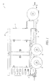
- FIG. 1 is a side view illustrating an example towable power generation system.
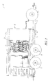
- FIG. 2 is a side view of the example towable power generation system shown in FIG. 1 where an enclosure is opened to expose the components inside the enclosure.
- FIG. 3 is an exploded side view of the example towable power generation system shown in FIG. 1 .
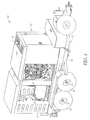
- FIG. 4 is a perspective view illustrating the example towable power generation system shown in FIG. 1 .
- FIG. 5 is a perspective view of the example towable power generation system shown in FIG. 4 where the enclosure is opened to expose the components inside the enclosure.
- FIG. 6 is an exploded perspective view of the example towable power generation system shown in FIG. 4 .
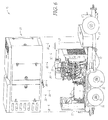
- FIGS. 7-8 are top views of the example towable power generation system shown in FIGS. 1 and 4 where the enclosure is removed from the rest of example towable power generation system.
- FIGS. 1-6 illustrate an example towable power generation system 10.
- the towable power generation system 10 includes an internal combustion engine 11 (see FIGS. 2 , 3 , 5 and 6 ) and an alternator 12 (see FIGS. 2 , 3 , 5 and 6 ) driven by the internal combustion engine 11 to generate electrical power.
- the towable power generation system 10 further includes a trailer 13 configured to be attached to a vehicle (not shown) that is adapted to tow the trailer 13.
- a base 14 e.g., a skid
- the trailer includes one or more axles 51, wheels 52, a frame 53 and a tongue 54 for attaching the trailer 50 to a towing vehicle.
- An enclosure 15 houses the internal combustion engine 11 and the alternator 12.
- the enclosure 15 is detachably connected to the base 14 using fasteners 16 (see, e.g., FIGS. 3 and 6 ) such that when the fasteners 16 are removed only the enclosure 15 is removed from the base 14 and every other part of the towable generator system 10 remains in place.
- the enclosure 15 may be formed as one-piece, or be formed of multiple components that are secured together to form a single enclosure. It should be noted that embodiments are contemplated where the enclosure 15 is removed from the base as one piece (see, e.g., FIGS. 3 and 6 ).
- the fasteners 16 are bolts that are removed to permit removal of the enclosure 15 from the base 14. It should be noted while the illustrated example embodiments illustrate the fasteners 16 as being bolts, any type of fastener (or combination of fasteners) that is known now or discovered in the future may be utilized in the towable power generation system 10 including, but not limited to, clamps, snaps, screws and rivets (among others).
- the towable power generation system 10 may further include a control panel 17 that is attached to the base 14.
- the control panel 17 includes wires (not shown) that provide signals and power to other parts of the towable power generation system 10.
- the control panel 17 remains in place when the enclosure 15 is removed from the base 14.
- the enclosure 15 may be removed from the base 14 such that no wires need to be disconnected from the control panel 17 when the enclosure 15 is removed from the base 14.
- the towable power generation system 10 further includes an exhaust system 18 that is attached to the internal combustion engine 11 to expel gases that are produced by the internal combustion engine 11 from the enclosure 15 when the enclosure 15 is attached to the base 14.
- the exhaust system 18 is not attached to the enclosure 15 such that the exhaust system 18 remains in place when the enclosure 15 is removed from the base 14. It should be noted that embodiments are contemplated where any combination of the internal combustion engine 11, the alternator 12 and the exhaust system 18 are able to operate when the enclosure 15 is removed from the base 14.
- the base 14 has a perimeter such that in some embodiments a user has access to each part of the towable power generation system 10 from around the entire perimeter of the base 14 when the enclosure 15 is removed from the base 14.
- FIG. 7 shows the user with access to the internal combustion engine 11
- FIG. 8 shows the user with access to the alternator 12.
- the towable power generation systems 10 described herein may allow an entire enclosure to be readily removed from the rest of the tawable power generation systems 10.
- the towable power generation systems 10 may also be able to provide ready access to portions of the internal combustion engine and/or the electrical alternator for repair or replacement when the enclosure is removed.
- the enclosure may be removed from the rest of the towable power generation system 10 without extensive disassembly of other components that form the towable power generation system 10.
Landscapes
- Engineering & Computer Science (AREA)
- Chemical & Material Sciences (AREA)
- Combustion & Propulsion (AREA)
- Mechanical Engineering (AREA)
- General Engineering & Computer Science (AREA)
- Physics & Mathematics (AREA)
- Acoustics & Sound (AREA)
- Connection Of Motors, Electrical Generators, Mechanical Devices, And The Like (AREA)
- Motor Or Generator Frames (AREA)
Abstract
Description
- Embodiments pertain to a towable generator, and more particularly to towable generator with a removable enclosure.
- Existing towable generators are typically used to provide temporary power at remote locations. As examples, such towable generators may be used to provide power at construction sites, emergency response sites or other locations that do not have ready access to utility power.
- The generators are typically mounted on a trailer in order to move the towable generator from/to a remote location. Conventional towable generators include some form of electric generator.
- One common type of electric generator includes an internal combustion engine that drives an electrical alternator to produce alternating electricity. The internal combustion engine and the electrical alternator are typically housed inside an enclosure that protects the internal combustion engine and the electrical alternator from the environment where the towable generator is located (or traveling through).
- One of the drawbacks with existing towable generators relates to the enclosures that house the internal combustion engine and the electrical alternator. The enclosures are often difficult to remove. In addition, usually only portions of the enclosure are available for removal, which prohibit/inhibits access to portions of the internal combustion engine and/or the electrical alternator for repair or replacement.
- Therefore, a need exists for a towable generator that includes an enclosure that is easily removable from the rest of towable generator. The enclosure of the towable generator should also be removed without extensive disassembly of other components that form the towable generator.
-
FIG. 1 is a side view illustrating an example towable power generation system. -
FIG. 2 is a side view of the example towable power generation system shown inFIG. 1 where an enclosure is opened to expose the components inside the enclosure. -
FIG. 3 is an exploded side view of the example towable power generation system shown inFIG. 1 . -
FIG. 4 is a perspective view illustrating the example towable power generation system shown inFIG. 1 . -
FIG. 5 is a perspective view of the example towable power generation system shown inFIG. 4 where the enclosure is opened to expose the components inside the enclosure. -
FIG. 6 is an exploded perspective view of the example towable power generation system shown inFIG. 4 . -
FIGS. 7-8 are top views of the example towable power generation system shown inFIGS. 1 and4 where the enclosure is removed from the rest of example towable power generation system. - The following description and the drawings sufficiently illustrate specific embodiments to enable those skilled in the art to practice them. Other embodiments may incorporate structural, logical, electrical, process, and other changes. Portions and features of some embodiments may be included in, or substituted for, those of other embodiments. Embodiments set forth in the claims encompass all available equivalents of those claims.
-
FIGS. 1-6 illustrate an example towablepower generation system 10. The towablepower generation system 10 includes an internal combustion engine 11 (seeFIGS. 2 ,3 ,5 and6 ) and an alternator 12 (seeFIGS. 2 ,3 ,5 and6 ) driven by theinternal combustion engine 11 to generate electrical power. - The towable
power generation system 10 further includes atrailer 13 configured to be attached to a vehicle (not shown) that is adapted to tow thetrailer 13. A base 14 (e.g., a skid) is attached to thetrailer 13 such that theinternal combustion engine 11 and thealternator 12 are mounted on thebase 14. In the illustrated example embodiments, the trailer includes one ormore axles 51,wheels 52, aframe 53 and a tongue 54 for attaching the trailer 50 to a towing vehicle. - An
enclosure 15 houses theinternal combustion engine 11 and thealternator 12. Theenclosure 15 is detachably connected to thebase 14 using fasteners 16 (see, e.g.,FIGS. 3 and6 ) such that when thefasteners 16 are removed only theenclosure 15 is removed from thebase 14 and every other part of thetowable generator system 10 remains in place. It should be noted that theenclosure 15 may be formed as one-piece, or be formed of multiple components that are secured together to form a single enclosure. It should be noted that embodiments are contemplated where theenclosure 15 is removed from the base as one piece (see, e.g.,FIGS. 3 and6 ). - In the illustrated example embodiments, the
fasteners 16 are bolts that are removed to permit removal of theenclosure 15 from thebase 14. It should be noted while the illustrated example embodiments illustrate thefasteners 16 as being bolts, any type of fastener (or combination of fasteners) that is known now or discovered in the future may be utilized in the towablepower generation system 10 including, but not limited to, clamps, snaps, screws and rivets (among others). - The towable
power generation system 10 may further include acontrol panel 17 that is attached to thebase 14. In some embodiments, thecontrol panel 17 includes wires (not shown) that provide signals and power to other parts of the towablepower generation system 10. - The
control panel 17 remains in place when theenclosure 15 is removed from thebase 14. In addition, theenclosure 15 may be removed from thebase 14 such that no wires need to be disconnected from thecontrol panel 17 when theenclosure 15 is removed from thebase 14. - In the illustrated example embodiments, the towable
power generation system 10 further includes anexhaust system 18 that is attached to theinternal combustion engine 11 to expel gases that are produced by theinternal combustion engine 11 from theenclosure 15 when theenclosure 15 is attached to thebase 14. In some embodiments, theexhaust system 18 is not attached to theenclosure 15 such that theexhaust system 18 remains in place when theenclosure 15 is removed from thebase 14. It should be noted that embodiments are contemplated where any combination of theinternal combustion engine 11, thealternator 12 and theexhaust system 18 are able to operate when theenclosure 15 is removed from thebase 14. - As shown in
FIGS. 7 and8 , thebase 14 has a perimeter such that in some embodiments a user has access to each part of the towablepower generation system 10 from around the entire perimeter of thebase 14 when theenclosure 15 is removed from thebase 14.FIG. 7 shows the user with access to theinternal combustion engine 11, andFIG. 8 shows the user with access to thealternator 12. - The towable
power generation systems 10 described herein may allow an entire enclosure to be readily removed from the rest of the tawablepower generation systems 10. The towablepower generation systems 10 may also be able to provide ready access to portions of the internal combustion engine and/or the electrical alternator for repair or replacement when the enclosure is removed. In addition, the enclosure may be removed from the rest of the towablepower generation system 10 without extensive disassembly of other components that form the towablepower generation system 10. - The Abstract is provided to comply with 37 C.F.R. Section 1.72(b) requiring an abstract that will allow the reader to ascertain the nature and gist of the technical disclosure. It is submitted with the understanding that it will not be used to limit or interpret the scope or meaning of the claims. The following claims are hereby incorporated into the detailed description, with each claim standing on its own as a separate embodiment.
Claims (14)
- A towable power generation system comprising:an internal combustion engine;an alternator driven by the internal combustion engine to generate electrical power;a trailer configured to be attached to a vehicle that is adapted to tow the trailer;a base attached to the trailer such that the internal combustion engine and the alternator are mounted on the base; andan enclosure that houses the internal combustion engine and the alternator, wherein the enclosure is detachably connected to the base using fasteners such that when the fasteners are removed only the enclosure is removed from the base and every other part of the towable generator remains in place.
- The towable power generation system of claim 1, wherein the enclosure is formed of multiple components that are secured together to form a single enclosure.
- The towable power generation system of claim 1, wherein the trailer includes at least one axle, at least one pair of wheels, a frame and a tongue adapted to attach the trailer to a moving vehicle.
- The towable power generation system of claim 1, wherein the towable generator further includes a control panel that is attached to the base.
- The towable power generation system of claim 4, wherein the control panel includes wires that provide signals and power to other parts of the towable generator, wherein the control panel remains in place when the enclosure is removed from the base.
- The towable power generation system of claim 5, wherein no wires need to be disconnected when the enclosure is removed from the base.
- The towable power generation system of claim 1, wherein the towable generator further includes an exhaust system that is attached to the internal combustion engine to expel gases from the enclosure when the enclosure is attached to the frame.
- The towable power generation system of claim 7, wherein the exhaust system is not attached to the enclosure.
- The towable power generation system of claim 7, wherein the exhaust system remains in place when the enclosure is removed from the base.
- The towable power generation system of claim 1, wherein the fasteners are bolts.
- The towable power generation system of claim 1, wherein the internal combustion engine and the alternator are able to operate when the enclosure is removed from the base.
- The towable power generation system of claim 11, further comprising an exhaust system attached to the internal combustion engine, wherein the internal combustion engine, the exhaust system and the alternator are able to operate when the enclosure is removed from the base.
- The towable power generation system of claim 1, wherein the enclosure is removed from the base as one piece.
- The towable power generation system of claim 1, wherein the base has a perimeter such that a user has access to each part of the towable generator from around the entire perimeter of the base when the enclosure is removed from the base.
Applications Claiming Priority (1)
| Application Number | Priority Date | Filing Date | Title |
|---|---|---|---|
| US13/659,958 US20140117675A1 (en) | 2012-10-25 | 2012-10-25 | Removable enclosure for a towable generator |
Publications (2)
| Publication Number | Publication Date |
|---|---|
| EP2725212A2 true EP2725212A2 (en) | 2014-04-30 |
| EP2725212A3 EP2725212A3 (en) | 2017-07-19 |
Family
ID=49485490
Family Applications (1)
| Application Number | Title | Priority Date | Filing Date |
|---|---|---|---|
| EP13188638.4A Withdrawn EP2725212A3 (en) | 2012-10-25 | 2013-10-15 | Removable enclosure for a towable generator |
Country Status (2)
| Country | Link |
|---|---|
| US (1) | US20140117675A1 (en) |
| EP (1) | EP2725212A3 (en) |
Cited By (1)
| Publication number | Priority date | Publication date | Assignee | Title |
|---|---|---|---|---|
| CN110657023A (en) * | 2019-10-28 | 2020-01-07 | 江苏沐阳智骅能源科技有限公司 | Multifunctional generator set |
Families Citing this family (1)
| Publication number | Priority date | Publication date | Assignee | Title |
|---|---|---|---|---|
| USD729736S1 (en) * | 2013-12-18 | 2015-05-19 | Cummins Power Generation Ip, Inc. | Genset enclosure |
Family Cites Families (14)
| Publication number | Priority date | Publication date | Assignee | Title |
|---|---|---|---|---|
| DE3410976A1 (en) * | 1983-03-18 | 1984-10-04 | Honda Giken Kogyo K.K., Tokio/Tokyo | COMPLETELY ENCLOSED, PORTABLE GENERATOR |
| US4835405A (en) * | 1987-11-30 | 1989-05-30 | Onan Corporation | Generator set and method |
| BE1008368A5 (en) * | 1994-04-05 | 1996-04-02 | Atlas Copco Airpower Nv | Housing for machines and devices that use of such housing. |
| US5965999A (en) * | 1997-03-20 | 1999-10-12 | Coleman Powermate, Inc. | Vertical generator assembly |
| US6084313A (en) * | 1998-08-13 | 2000-07-04 | Coleman Powermate, Inc. | Generator system with vertically shafted engine |
| US7034410B2 (en) * | 2000-06-23 | 2006-04-25 | Gino Kennedy | Compact auxiliary power generator |
| JP2006528477A (en) * | 2003-06-17 | 2006-12-14 | ブラック アンド デッカー インコーポレーテッド | Generator having dual-path airflow cooling structure and method therefor |
| US7695049B2 (en) * | 2004-05-04 | 2010-04-13 | Colborne Bruce J | Inner supported climate controlled single trailer shelter |
| US7089889B2 (en) * | 2004-05-14 | 2006-08-15 | Powermate Corporation | Generator having a plastic frame |
| US7318608B2 (en) * | 2004-12-23 | 2008-01-15 | Ingersoll-Rand Company | Running gear with integral engine supports |
| EP1829190A4 (en) * | 2004-12-23 | 2009-07-29 | Doosan Internat Usa Inc | SENSOR SPEAKER WITH INTEGRATED COOLING DUCTS |
| US7499263B2 (en) * | 2005-08-30 | 2009-03-03 | Doosan Infracore Co., Ltd. | Mobile power source cable connection system and method |
| WO2008024686A2 (en) * | 2006-08-19 | 2008-02-28 | Konop Chad O | Improved portable generator housing |
| US7902705B2 (en) * | 2007-02-06 | 2011-03-08 | Cummins Power Generation, Inc. | Generator housing, transport mechanism for the same, and cooling and sound attenuation method for the same |
-
2012
- 2012-10-25 US US13/659,958 patent/US20140117675A1/en not_active Abandoned
-
2013
- 2013-10-15 EP EP13188638.4A patent/EP2725212A3/en not_active Withdrawn
Non-Patent Citations (1)
| Title |
|---|
| None |
Cited By (1)
| Publication number | Priority date | Publication date | Assignee | Title |
|---|---|---|---|---|
| CN110657023A (en) * | 2019-10-28 | 2020-01-07 | 江苏沐阳智骅能源科技有限公司 | Multifunctional generator set |
Also Published As
| Publication number | Publication date |
|---|---|
| US20140117675A1 (en) | 2014-05-01 |
| EP2725212A3 (en) | 2017-07-19 |
Similar Documents
| Publication | Publication Date | Title |
|---|---|---|
| US8960708B2 (en) | Enclosure guide system for a towable generator | |
| CN101331059B (en) | Modular aircraft ground support cart | |
| US20080123375A1 (en) | Multi-Mode Power Converter | |
| DE102018127356B4 (en) | CABLE GUIDE ASSEMBLY AND METHOD | |
| US20110253463A1 (en) | Modular hybrid electric vehicle system | |
| US20120294015A1 (en) | Powered Base for a Lamp | |
| WO2013030637A3 (en) | Feeding connector for feeding electric power from vehicle to external power receiving device, method for identifying the connector, system for identifying the connector, and feeding system using the connector | |
| FR2962943B1 (en) | DEVICE FOR REMOVABLE FASTENING OF A BATTERY OF A MOTOR VEHICLE. | |
| WO2012168133A3 (en) | Battery system, motor vehicle comprising said battery system, and method for producing a ready status for a motor vehicle comprising said battery system | |
| WO2015006277A3 (en) | Light vehicles with on-board rapid charging systems and associated methods | |
| JP5983962B2 (en) | Electronic device, case and bobbin holder | |
| FR2982566B1 (en) | MODULAR VEHICLE | |
| US8991274B2 (en) | Mounting surface of an agricultural work vehicle power takeoff system | |
| WO2020102478A3 (en) | Modular vehicle architecture enabling range on demand | |
| US20140117675A1 (en) | Removable enclosure for a towable generator | |
| CN206834226U (en) | Battery pack assembly and vehicle | |
| EP2266828A3 (en) | Assembly for integrating electrical storage modules into the bodywork of a motor vehicle | |
| FR2964622B1 (en) | DEVICE FOR FIXING AN ELECTRIC BATTERY TO A CHASSIS OF A MOTOR VEHICLE | |
| US20180229594A1 (en) | Covering of an Outer Sill, Energy Storage Element and Vehicle | |
| EP2093088A3 (en) | Multi-purpose mixed-power vehicle | |
| CN104158275A (en) | Electric generator for external hanging electric vehicle | |
| CN104442419A (en) | Automobile using multiple kinds of energy | |
| CN203921205U (en) | Multi-axis aircraft electric motor mounting structure | |
| CN202271911U (en) | Rescuing system for automobile on road | |
| PH12021551277B1 (en) | An electric vehicle |
Legal Events
| Date | Code | Title | Description |
|---|---|---|---|
| PUAI | Public reference made under article 153(3) epc to a published international application that has entered the european phase |
Free format text: ORIGINAL CODE: 0009012 |
|
| 17P | Request for examination filed |
Effective date: 20131015 |
|
| AK | Designated contracting states |
Kind code of ref document: A2 Designated state(s): AL AT BE BG CH CY CZ DE DK EE ES FI FR GB GR HR HU IE IS IT LI LT LU LV MC MK MT NL NO PL PT RO RS SE SI SK SM TR |
|
| AX | Request for extension of the european patent |
Extension state: BA ME |
|
| PUAL | Search report despatched |
Free format text: ORIGINAL CODE: 0009013 |
|
| AK | Designated contracting states |
Kind code of ref document: A3 Designated state(s): AL AT BE BG CH CY CZ DE DK EE ES FI FR GB GR HR HU IE IS IT LI LT LU LV MC MK MT NL NO PL PT RO RS SE SI SK SM TR |
|
| AX | Request for extension of the european patent |
Extension state: BA ME |
|
| RIC1 | Information provided on ipc code assigned before grant |
Ipc: F02B 77/13 20060101ALI20170613BHEP Ipc: F02B 63/04 20060101AFI20170613BHEP |
|
| STAA | Information on the status of an ep patent application or granted ep patent |
Free format text: STATUS: THE APPLICATION IS DEEMED TO BE WITHDRAWN |
|
| 18D | Application deemed to be withdrawn |
Effective date: 20180120 |