EP2725085B1 - A composite comprising a polymer and a blue phase liquid crystal, a method for preparing the composite, and a liquid crystal display device comprising the composite - Google Patents
A composite comprising a polymer and a blue phase liquid crystal, a method for preparing the composite, and a liquid crystal display device comprising the composite Download PDFInfo
- Publication number
- EP2725085B1 EP2725085B1 EP13188885.1A EP13188885A EP2725085B1 EP 2725085 B1 EP2725085 B1 EP 2725085B1 EP 13188885 A EP13188885 A EP 13188885A EP 2725085 B1 EP2725085 B1 EP 2725085B1
- Authority
- EP
- European Patent Office
- Prior art keywords
- liquid crystal
- composite
- acrylate
- blue phase
- methyl
- Prior art date
- Legal status (The legal status is an assumption and is not a legal conclusion. Google has not performed a legal analysis and makes no representation as to the accuracy of the status listed.)
- Active
Links
Images
Classifications
-
- C—CHEMISTRY; METALLURGY
- C09—DYES; PAINTS; POLISHES; NATURAL RESINS; ADHESIVES; COMPOSITIONS NOT OTHERWISE PROVIDED FOR; APPLICATIONS OF MATERIALS NOT OTHERWISE PROVIDED FOR
- C09K—MATERIALS FOR MISCELLANEOUS APPLICATIONS, NOT PROVIDED FOR ELSEWHERE
- C09K19/00—Liquid crystal materials
- C09K19/52—Liquid crystal materials characterised by components which are not liquid crystals, e.g. additives with special physical aspect: solvents, solid particles
- C09K19/54—Additives having no specific mesophase characterised by their chemical composition
- C09K19/542—Macromolecular compounds
-
- C—CHEMISTRY; METALLURGY
- C09—DYES; PAINTS; POLISHES; NATURAL RESINS; ADHESIVES; COMPOSITIONS NOT OTHERWISE PROVIDED FOR; APPLICATIONS OF MATERIALS NOT OTHERWISE PROVIDED FOR
- C09K—MATERIALS FOR MISCELLANEOUS APPLICATIONS, NOT PROVIDED FOR ELSEWHERE
- C09K19/00—Liquid crystal materials
- C09K19/02—Liquid crystal materials characterised by optical, electrical or physical properties of the components, in general
- C09K19/0275—Blue phase
-
- C—CHEMISTRY; METALLURGY
- C09—DYES; PAINTS; POLISHES; NATURAL RESINS; ADHESIVES; COMPOSITIONS NOT OTHERWISE PROVIDED FOR; APPLICATIONS OF MATERIALS NOT OTHERWISE PROVIDED FOR
- C09K—MATERIALS FOR MISCELLANEOUS APPLICATIONS, NOT PROVIDED FOR ELSEWHERE
- C09K19/00—Liquid crystal materials
- C09K19/52—Liquid crystal materials characterised by components which are not liquid crystals, e.g. additives with special physical aspect: solvents, solid particles
- C09K19/54—Additives having no specific mesophase characterised by their chemical composition
-
- C—CHEMISTRY; METALLURGY
- C09—DYES; PAINTS; POLISHES; NATURAL RESINS; ADHESIVES; COMPOSITIONS NOT OTHERWISE PROVIDED FOR; APPLICATIONS OF MATERIALS NOT OTHERWISE PROVIDED FOR
- C09K—MATERIALS FOR MISCELLANEOUS APPLICATIONS, NOT PROVIDED FOR ELSEWHERE
- C09K19/00—Liquid crystal materials
- C09K19/52—Liquid crystal materials characterised by components which are not liquid crystals, e.g. additives with special physical aspect: solvents, solid particles
- C09K19/54—Additives having no specific mesophase characterised by their chemical composition
- C09K19/542—Macromolecular compounds
- C09K19/544—Macromolecular compounds as dispersing or encapsulating medium around the liquid crystal
-
- C—CHEMISTRY; METALLURGY
- C09—DYES; PAINTS; POLISHES; NATURAL RESINS; ADHESIVES; COMPOSITIONS NOT OTHERWISE PROVIDED FOR; APPLICATIONS OF MATERIALS NOT OTHERWISE PROVIDED FOR
- C09K—MATERIALS FOR MISCELLANEOUS APPLICATIONS, NOT PROVIDED FOR ELSEWHERE
- C09K19/00—Liquid crystal materials
- C09K19/52—Liquid crystal materials characterised by components which are not liquid crystals, e.g. additives with special physical aspect: solvents, solid particles
-
- C—CHEMISTRY; METALLURGY
- C09—DYES; PAINTS; POLISHES; NATURAL RESINS; ADHESIVES; COMPOSITIONS NOT OTHERWISE PROVIDED FOR; APPLICATIONS OF MATERIALS NOT OTHERWISE PROVIDED FOR
- C09K—MATERIALS FOR MISCELLANEOUS APPLICATIONS, NOT PROVIDED FOR ELSEWHERE
- C09K19/00—Liquid crystal materials
- C09K19/52—Liquid crystal materials characterised by components which are not liquid crystals, e.g. additives with special physical aspect: solvents, solid particles
- C09K19/54—Additives having no specific mesophase characterised by their chemical composition
- C09K19/542—Macromolecular compounds
- C09K2019/546—Macromolecular compounds creating a polymeric network
Definitions
- the present invention relates to the field of liquid crystal display (LCD) technology. More particularly, the present invention relates to a composite comprising a polymer and a blue phase liquid crystal (BPLC), a method for preparing the composite, and a LCD device comprising the composite.
- LCD liquid crystal display
- BPLC blue phase liquid crystal
- the blue phase liquid crystal display (BP-LCD) technology has the following four outstanding advantages over the conventional LCD technologies.
- the blue phase liquid crystal exhibits a fast response at microsecond level to an electric field, is applicable to a field sequential driving mode, and does not need a color filter.
- the blue phase liquid crystal macroscopically exhibits optical isotropy, so that the alignment of the inner surface of a display substrate is no longer required.
- the BP-LCDs can provide a relatively wide viewing performance and do not need any viewing angle compensation film.
- the transmittance of the light from the backlights of the BP-LCDs is insensitive to the substrate gap, and thus the substrate gap does not need to be strictly controlled during the fabrication process.
- Such a feature of the BP-LCDs can greatly simplify the fabrication process and is useful for manufacturing large LCD panels.
- a BP-LCD may reduce the backlight power consumption by about 1/3, the energy consumption during its fabrication may reduce by about 40%, and the cost of raw materials thereof may reduce by about 19%. Since the techniques and processes of manufacturing a BP-LCD are similar to that of the conventional LCD, they can be produced by the same manufacturing facilities. So, the key points of improving the BP-LCD technology reside in the development of blue phase liquid crystal (BPLC) materials.
- BPLC blue phase liquid crystal
- a polymer-dispersed liquid crystal is a composite formed by uniformly dispersing nematic liquid crystal droplets in a polymer matrix. Because the polymer-dispersed liquid crystal has excellent electro-optical properties and is easy to achieve large-scale production, it has been widely used in large-size flexible display devices, non-linear optical materials, electronically-controlled smart glass, liquid crystal gratings and so on.
- International patent application WO 2011/120637 A2 discloses a method of stabilizing a blue phase liquid crystal composition, said method comprising: a) providing a liquid crystal composition, said liquid crystal composition being capable of forming a blue phase, said liquid crystal composition comprising a liquid crystal material and a monomer which can be induced to polymerize, b) inducing the liquid crystal composition to form a blue phase and maintaining said liquid crystal composition in said blue phase, c) inducing said monomer to polymerize whilst said liquid crystal composition is maintained in said blue phase, thereby stabilizing said liquid crystal composition, wherein, prior to steps b) and c), in step a) a solid porous matrix is prepared or provided which has an interstitial space which can be filled by a liquid material or liquid crystal material, and, also prior to step b) and c), said liquid crystal composition is introduced into said interstitial space of said solid porous matrix.
- US patent application US 2008/280071 A1 discloses a polymer/liquid crystal composite, which includes a liquid crystal material which exhibits an optically isotropic liquid crystal phase in the temperature range of approximately 5°C or more in the elevated temperature process but does not exhibit a nematic phase; and a polymer, and which is used for an element driven in a state of the optically isotropic liquid crystal phase.
- US patent application US 2009/322997A1 discloses a liquid crystal display device having at least a pair of transparent substrates, polymer-stabilized blue phase liquid crystal layer disposed therebetween, and a transparent film having an absolute value
- Japanese patent JP 3779937 B2 discloses a liquid crystal material for optical modulation elements comprising the blue phase of a composite liquid crystal composition (polymer network/low molecular liquid crystal) which comprises a low molecule liquid crystal capable of developing the blue phase between a cholesteric phase and an isotropic phase, and a polymer network formed in the low molecule liquid crystal by polymerizing an amorphous monomer (for example, an alkyl group side chain-having acrylate-based monomer) together with a crosslinking agent.
- a composite liquid crystal composition polymer network/low molecular liquid crystal
- a low molecule liquid crystal capable of developing the blue phase between a cholesteric phase and an isotropic phase
- a polymer network formed in the low molecule liquid crystal by polymerizing an amorphous monomer (for example, an alkyl group side chain-having acrylate-based monomer) together with a crosslinking agent.
- Chinese patent application CN 1022345 A discloses a blue phase (BP) liquid crystal composition, a method of stabilizing a blue phase state of a liquid crystal material, a method of lowering the operating voltage of a liquid crystal material. Moreover, it is disclosed a blue phase crystal material stabilized by said method or having an operating voltage that is lowered by said the method. It is further disclosed a liquid crystal cell comprising a blue phase liquid crystal material and a liquid crystal display comprising a blue phase liquid crystal material. Furthermore, a method of broadening that stability temperature range of a liquid crystal material in its blue phase state is disclosed.
- BP blue phase
- Chinese patent application CN 102517040 A discloses a blue phase liquid crystal material, which comprises a liquid crystal main body, a chiral reagent and a stable polymer.
- the chiral reagent is R811; the stable polymer is formed by photo-polymerizing a first monomer and a second monomer; the first monomer is ethylhexyl acrylate (2-EHA); and the second monomer is 2-methyl-1,4-di ⁇ 4-[(3-acrylate) propoxyl] phenylformic acid ⁇ phenylester (PTPTP).
- Chinese patent application CN 102652167 A discloses a liquid crystal/polymer composite comprising: a liquid crystal material which presents a blue phase; a polymer which supports the liquid crystal material using a dendrimer-type structure formed from dendrimer-type units, wherein 2 or more atoms having a branched structure bond with a central atom and the order is 2 or greater, and polymer units, wherein polymer groups bond to the termini of the bonds of the dendrimer-type units and bond to other polymer groups; and a chiral agent which is present in the spaces of the liquid crystal material and controls the orientation of the liquid crystal material.
- US patent application US 2012/0235088 A1 discloses to a blue phase (BP) liquid crystal composition that shows reduced hysteresis behavior, and to a method of reducing and/or eliminating the hysteresis behavior of a BP liquid crystal composition. Moreover, the present invention relates to a blue phase liquid crystal composition, wherein the hysteresis has been reduced or eliminated. Furthermore, the present invention relates to a liquid crystal cell comprising a blue phase liquid crystal composition, and to a liquid crystal display comprising a blue phase liquid crystal composition.
- BP blue phase
- Chinese patent application CN 102902092 A discloses a blue phase liquid crystal display panel and a manufacturing method thereof.
- the manufacturing method of the lue phase liquid crystal display panel comprises the steps of providing a first substrate and a second substrate; then, filling a blue phase liquid crystal composition between the first substrate and the second substrate, wherein the blue phase liquid crystal composition comprises a blue phase liquid crystal and reactive monomers; and then performing an irradiation procedure to make the reactive monomers in the blue phase liquid crystal composition generate a polymerization reaction, wherein the optical wavelength used in the irradiation procedure is 200-350 nm.
- the present invention provides a novel composite comprising a polymer and a BPLC, a method of preparing the composite, and a LCD device comprising the composite.
- a composite comprising a polymer and a blue phase liquid crystal.
- the composite is characterized in that the polymer is a crosslinked and non-liquid crystalline polymer, the blue phase liquid crystal is dispersed in said polymer, and the ratio of the polymer to the blue phase liquid crystal by weight (W p /W l ) satisfies the relationship 12 : 88 ⁇ W p /M l ⁇ 30 : 70, wherein the W p is the weight of the polymer, and W l is the weight of the blue phase liquid crystal.
- the ratio of the polymer to the blue phase liquid crystal by weight (W p /M l ) satisfies 15 : 85 ⁇ W p /W l ⁇ 25 : 75, and most preferably the ratio W p /W l is 20 : 80.
- a method is provided to prepare the composite comprising a polymer and a blue phase liquid crystal.
- the method includes the following steps:
- the blue phase liquid crystal prefers to be a blue phase liquid crystal which exhibits a temperature range of blue phase of more than 5.0 °C, and has a viscosity of 34 to 45 mPa ⁇ s, a melting point of -20 °C to -15 °C, and a clearing point of 68 to 88 °C.
- the ratio W c /W l satisfies 15 : 85 ⁇ W c /W l ⁇ 25 : 75, and more preferably the ratio W c /W l is 20 : 80.
- said non-liquid crystalline compound having a photopolymerizable functional group is a monomer for forming the polymer contained in the composite of the present invention.
- the monomer preferably comprises at least one multifunctional (methyl)acrylate and at least one monofunctional (methyl)acrylate, each of which is a photo-polymerizable compound.
- the ratio of the total monofunctional (methyl)acrylate to the total multifunctional (methyl)acrylate on a molar basis is 1:1 to 1:9, and preferably is 1:4.
- the amount of the photoinitiator is 0.5% to 1.5% by weight, in relative to the total amount of the non-liquid crystalline compound having a photopolymerizable functional group.
- said photoinitiator is a UV-light initiator.
- the photo-polymerizable compound (monomer) undergoes polymerization and crosslinking, so as to form a polymer network, and thereby giving the composite of the present invention.
- a liquid crystal display device comprising a pair of substrates and the composite of the present invention. At least one of the substrates has an electrode formed thereon, and the composite is enclosed and sealed between the pair of substrates.
- the present invention relates to a composite comprising a polymer and a blue phase liquid crystal.
- the polymer is a crosslinked and non-liquid crystalline polymer, and the blue phase liquid crystal is dispersed in said polymer.
- the ratio of the polymer to the blue phase liquid crystal by weight (W p /W l ) satisfies the relationship 12 : 88 ⁇ W p /W l ⁇ 30 : 70, wherein the W p is the weight of the polymer, and W l is the weight of the blue phase liquid crystal. More preferably, the ratio W p /W l satisfies 15 : 85 ⁇ W p /W l ⁇ 25 : 75, and most preferably the ratio W p /W l is 20 : 80.
- the present invention also relates to a method for preparing the composite comprising a polymer and a blue phase liquid crystal.
- the method includes the following steps:
- the blue phase liquid crystal prefers to be a blue phase liquid crystal which exhibits a temperature range of blue phase of more than 5.0 °C, and has a viscosity of 34 to 45 mpa ⁇ s, a melting point of-20 °C to -15 °C, and a clearing point of 68 to 88 ° C.
- the ratio W c /W l satisfies 15 : 85 ⁇ W c /W l ⁇ 25 : 75, and more preferably the ratio W c /W l is 20 : 80.
- said non-liquid crystalline compound having a photopolymerizable functional group is a monomer for forming the polymer contained in the composite of the present invention.
- the monomer preferably comprises at least one multifunctional (methyl)acrylate and at least one monofunctional (methyl)acrylate, each of which is a photo-polymerizable compound.
- the ratio of the total monofunctional (methyl)acrylate to the total multifunctional (methyl)acrylate on a molar basis is 1:1 to 1:9, and preferably is 1:4.
- the term "photopolymerizable” means that the polymerizable monomer undergoes a polymerization and crosslinking reaction under the irradiation of a light, and it usually means a polymerization under the irradiation of ultraviolet (UV) light.
- UV ultraviolet
- the term "(methyl)acrylate” refers to a photopolymerizable compound having a (methyl)acryl group, preferably a (methyl)acrylate group.
- the term “(methyl)acrylate” means both acrylate and methacrylate.
- the (methyl)acrylate is a monofunctional or a multifunctional (methyl)acrylate.
- the multifunctional (methyl)acrylate useful in the present invention includes but is not limited to a photopolymerizable compound having 2 or 3 (methyl)acrylate groups, and for example, may be selected from the group consisting of butanediol diacrylate (BDDA), trimethylolpropane triacrylate (TMPTA), 4-[2-methyl-4-(4-acryloxylpropoxyl) benzoyloxy]phenoxycarbonyl-phenoxylpropyl acrylate and a combination thereof.
- BDDA butanediol diacrylate
- TMPTA trimethylolpropane triacrylate
- the monofunctional (methyl)acrylate useful in the present invention includes but is not limited to a photopolymerizable compound having 1 (methyl)acrylate group, and for example, may be selected from the group consisting of (2,2,5-trimethyl)hexyl acrylate (TMHA), (2-ethyl)hexyl acrylate, and a combination thereof.
- the photoinitiator is used in an amount sufficient to initiate the polymerization reaction.
- the amount of the photoinitiator is 0.5% to 1.5% by weight, in relative to the total amount of the non-liquid crystalline compound having a photopolymerizable functional group.
- said photoinitiator is a UV-light initiator.
- the photo-polymerizable compound (monomer) undergoes polymerization and crosslinking reaction, so as to form a polymer network, and thereby giving the composite of the present invention.
- the irradiation can be usually carried out at a dosage of 2-10 mW/cm 2 , for a time period of several minutes to several hours, usually 0.5 hour or more, for example, 0.5-5h, 0.5-3h, or 0.5-1 h.
- the present invention also relates to a liquid crystal display device, which comprises a pair of substrates and the composite of the present invention. At least one of the substrates has an electrode formed thereon, and the composite is enclosed and sealed between the pair of substrates.
- the composite, the method for preparing the composite and the LCD device of the present invention will be illustrated in detail by the following Examples. But the present invention is not limited thereto.
- Step 1 preparation of a BPLC exhibiting a wide temperature range
- the BPLC exhibits a temperature range of blue phase of about 10.0 °C.
- the chiral compound R811 and Iso-(6OBA) 2 (commercially available from Merk GmbH, Germany) are represented by the following structural formulas:
- the BPLC has a viscosity of 35 mpa ⁇ s, a melting point of -15 °C, and a clearing point of 86 °C.
- the BPLC was prepared by the following procedures:
- the 82.0 wt% of SLC-X, 10.0 wt% of R811 and 8.0 wt% of Iso-(6OBA) 2 were mixed together and then heated to a temperature above the clearing point (higher than the clearing point by about 5-10 °C), and maintained for about 30 minutes with sufficient agitation by a magnetic stirrer.
- the desired BPLC material was obtained.
- Step 2 preparation of a reaction mixture
- TMHA and BDDA which structures are shown in Figure 1
- polymeric monomers that is, the non-liquid crystalline compounds having photopolymerizable functional group(s)
- ratio on a molar basis of TMHA / BDDA was 1:4.
- a blend was prepared by blending the polymeric monomers with the BPLC material at a mixing ratio by weight of 30:70 at room temperature. Then into the blend, a photoinitiator (which structure is shown in Figure 2 ) was added at a ratio by weight of about 1% based on the total amount of the non-liquid crystalline compounds having photopolymerizable functional group(s). Upon stirring sufficiently, a homogeneous reactive mixture was obtained.
- Step 3 preparation of a composite
- the homogeneous reactive mixture obtained in Step 2 was injected into a liquid crystal cell by means of siphon action to prepare a sample.
- the liquid crystal cell is a IPS cell, with the electrode width being 5.0 micrometers, the distance between the electrodes being 5.0 micrometers, and the cell gap being maintained at 10.0 micrometers by spacers.
- the sample was kept on a heating stage (Linkam LK-600PM) of which the temperature was precisely controlled with an accuracy of 0.1 °C, so that the BPLC maintained in the blue phase.
- the sample was irradiated with a UV light at a dosage of 5 mW/cm 2 for 40 minutes.
- the non-liquid crystalline compounds having photopolymerizable functional group(s) proceeded to perform a crosslinking reaction to form a polymer network, and thus, the composite of Example 1 was obtained.
- Step 4 measurement of the properties of the composite
- the BPLC texture of the composite was observed with a polarizing microscope equipped with a heating stage and the phase transition temperature was determined.
- the electro-optical properties of the composite were determined by a Liquid Crystal Parameters Tester (LCT-5016C, Changchun Liancheng Instrument Co. Ltd.).
- the electro-optical properties of the composite prepared according to the present invention were tested by a process described below.
- the test of the electro-optical properties was mainly performed to measure the electrically-induced birefringence, ⁇ n induced , of each of the composites.
- the composite of the present invention is optically isotropic when no external electric field (E) is applied. With increase of the electric field applied, the composite becomes anisotropic along the direction of the electric field.
- E electric field
- the reactive mixture prepared by Step 2 was injected by means of siphon action into a liquid crystal cell provided with in-plane electrodes (IPS cell, with the electrode width being 5.0 micrometers, the distance between the electrodes being 5.0 micrometers, and the cell gap being maintained at 10.0 micrometers by spacers).
- IPS cell in-plane electrodes
- the resultant sample was oriented at an angle of 45° with respect to the direction of incident light.
- the temperature was precisely controlled (with an accuracy of 0.1 °C) by a heating stage (Linkam LK-600PM).
- I out I in sin 2 ⁇ / 2 wherein I in is the intensity of incident light, I out is the intensity of output light, ⁇ is the optical retardation angle.
- the composite was observed with the polarizing microscope and confirmed to have a BPLC texture.
- the phase transition temperature was also determined with the polarizing microscope.
- the composite of Example 1 was found to have a temperature range of blue phase greater than 60 °C (about from 10°C to 70°C).
- the electro-optical properties of the composite were measured with the Liquid Crystal Parameters Tester, and Figure 4 shows the voltage - transmittance curve of the composite.
- the transmittance shown in the figure is normalized with the transmittance of the air which is 100%.
- the driving voltage of the composite sample is determined as the voltage corresponding to the transmittance peak in the voltage - transmittance curve.
- the response speed is determined as the sum of the response time during ON state and OFF state. As a result, the composite sample exhibited a driving voltage of about 110 V and a response speed of less than 1 ms.
- Step 1 preparation of a BPLC exhibiting a wide temperature range
- the BPLC exhibits a temperature range of blue phase of about 10.0 °C.
- the chiral compound R811 and Iso-(6OBA) 2 (commercially available from Merk GmbH, Germany) are represented by the following structural formulas:
- the BPLC has a viscosity of 35 mPa ⁇ s, a melting point of -15 °C, and a clearing point of 86 °C.
- the BPLC was prepared by the following procedures:
- Step 2 preparation of a reaction mixture
- TMHA and BDDA which structures are shown in Figure 1
- polymeric monomers that is, the non-liquid crystalline compounds having photopolymerizable functional group(s)
- ratio on a molar basis of TMHA / BDDA was 1:4.
- a blend was prepared by blending the polymeric monomers with the BPLC material at a mixing ratio by weight of 10:90 at room temperature. Then into the blend, a photoinitiator (which structure is shown in Figure 2 ) was added at a ratio by weight of about 1% based on the total amount of the non-liquid crystalline compounds having photopolymerizable functional group(s). Upon stirring sufficiently, a homogeneous reactive mixture was obtained.
- Step 3 preparation of a composite
- the homogeneous reactive mixture obtained in Step 2 was injected into a liquid crystal cell by means of siphon action to prepare a sample.
- the liquid crystal cell is a IPS cell, with the electrode width being 5.0 micrometers, the distance between the electrodes being 5.0 micrometers, and the cell gap being maintained at 10.0 micrometers by spacers.
- the sample was kept on a heating stage (Linkam LK-600PM) of which the temperature was precisely controlled with an accuracy of 0.1 °C, so that the BPLC maintained in the blue phase.
- the sample was irradiated with a UV light at a dosage of 5 mW/cm 2 for 30 minutes.
- the non-liquid crystalline compounds having photopolymerizable functional group(s) proceeded to perform a crosslinking reaction to form a polymer network, and thus, the composite of Comparative Example was obtained.
- Step 4 measurement of the properties of the composite
- the resultant composite was observed with the polarizing microscope equipped with a heating stage according to the same method as described in Example 1.
- the composite was confirmed to have a BPLC texture and the phase transition temperature was determined.
- the composite of this Comparative Example was found to have a temperature range of blue phase greater than 30 °C (about from 20°C to 50 °C).
- the electro-optical properties of the composite were measured by a Liquid Crystal Parameters Tester according to the same method as described in Example 1, and Figure 3 shows the voltage - transmittance curve of the composite.
- the composite sample exhibited a driving voltage of about 100 V and a response speed of less than 1 ms.
- Step 1 preparation of a BPLC exhibiting a wide temperature range
- the BPLC exhibits a temperature range of blue phase of about 8.0 °C.
- the chiral compound R811 is represented by the following structural formula:
- the BPLC has a viscosity of 45 mPa ⁇ s, a melting point of -20 °C, and a clearing point of 68 °C.
- the BPLC was prepared by the following procedures:
- Step 2 preparation of a reaction mixture
- TMHA and TMPTA (which structures are shown in Figure 1 ) were employed as polymeric monomers (that is, the non-liquid crystalline compounds having photopolymerizable functional group(s)) and the ratio on a molar basis of TMHA / TMPTA was 1:4.
- a blend was prepared by blending the polymeric monomers with the BPLC material at a mixing ratio by weight of 30:70 at room temperature. Then into the blend, a photoinitiator (which structure is shown in Figure 2 ) was added at a ratio by weight of about 1% based on the total amount of the non-liquid crystalline compounds having photopolymerizable functional group(s). Upon stirring sufficiently, a homogeneous reactive mixture was obtained.
- Step 3 preparation of a composite
- the homogeneous reactive mixture obtained in Step 2 was injected into a liquid crystal cell by means of siphon action to prepare a sample.
- the liquid crystal cell is a IPS cell, with the electrode width being 5.0 micrometers, the distance between the electrodes being 5.0 micrometers, and the cell gap being maintained at 10.0 micrometers by spacers.
- the sample was kept on a heating stage (Linkam LK-600PM) of which the temperature was precisely controlled with an accuracy of 0.1 ° C, so that the BPLC maintained in the blue phase.
- the sample was irradiated with a UV light at a dosage of 5 mW/cm 2 for 30 minutes.
- the non-liquid crystalline compounds having photopolymerizable functional group(s) proceeded to perform a crosslinking reaction to form a polymer network, and thus, the composite of Example 2 was obtained.
- Step 4 measurement of the properties of the composite
- the resultant composite was observed with the polarizing microscope equipped with a heating stage according to the same method as described in Example 1.
- the composite was confirmed to have a BPLC texture and the phase transition temperature was determined.
- the composite of this Example was found to have a temperature range of blue phase greater than 70 °C (about from 5 °C to 75 °C).
- the electro-optical properties of the composite were measured by a Liquid Crystal Parameters Tester according to the same method as described in Example 1, and Figure 5 shows the voltage - transmittance curve of the composite.
- the composite sample exhibited a driving voltage of about 120 V and a response speed of less than 1 ms.
- Step 1 preparation of a BPLC exhibiting a wide temperature range
- the BPLC exhibits a temperature range of blue phase of about 5.0 °C.
- the BPLC has a viscosity of 34 mPa ⁇ s, a melting point of -16 °C, and a clearing point of 88 °C.
- the BPLC was prepared by the following procedures:
- Step 2 preparation of a reaction mixture
- TMHA, BDDA and TMPTA (which structures are shown in Figure 1 ) were employed as polymeric monomers (that is, the non-liquid crystalline compounds having photopolymerizable functional group(s)) and the ratio on a molar basis of TMHA / BDDA / TMPTA was 1:2:3.
- a blend was prepared by blending the polymeric monomers with the BPLC material at a mixing ratio by weight of 20:80 at room temperature. Then into the blend, a photoinitiator (which structure is shown in Figure 2 ) was added at a ratio by weight of about 1% based on the total amount of the non-liquid crystalline compounds having photopolymerizable functional group(s). Upon stirring sufficiently, a homogeneous reactive mixture was obtained.
- Step 3 preparation of a composite
- the homogeneous reactive mixture obtained in Step 2 was injected into a liquid crystal cell by means of siphon action to prepare a sample.
- the liquid crystal cell is a IPS cell, with the electrode width being 5.0 micrometers, the distance between the electrodes being 5.0 micrometers, and the cell gap being maintained at 10.0 micrometers by spacers.
- the sample was kept on a heating stage (Linkam LK-600PM) of which the temperature was precisely controlled with an accuracy of 0.1 °C, so that the BPLC maintained in the blue phase.
- the sample was irradiated with a UV light at a dosage of 5 mW/cm 2 for 30 minutes.
- the non-liquid crystalline compounds having photopolymerizable functional group(s) proceeded to perform a crosslinking reaction to form a polymer network, and thus, the composite of Example 3 was obtained.
- Step 4 measurement of the properties of the composite
- the resultant composite was observed with the polarizing microscope equipped with a heating stage according to the same method as described in Example 1.
- the composite was confirmed to have a BPLC texture and the phase transition temperature was determined.
- the composite of this Example was found to have a temperature range of blue phase greater than 60 °C (about from 10 °C to 70 ° C).
- the electro-optical properties of the composite were measured by a Liquid Crystal Parameters Tester according to the same method as described in Example 1, and Figure 6 shows the voltage - transmittance curve of the composite.
- the composite sample exhibited a driving voltage of about 105 V and a response speed of less than 1 ms.
- Step 1 preparation of a BPLC exhibiting a wide temperature range
- the BPLC exhibits a temperature range of blue phase of about 5.0 °C.
- the BPLC has a viscosity of 34 mpa ⁇ s, a melting point of -16 °C, and a clearing point of 88 °C.
- the BPLC was prepared by the following procedures:
- Step 2 preparation of a reaction mixture
- TMHA, BDDA and TMPTA (which structures are shown in Figure 1 ) were employed as polymeric monomers (that is, the non-liquid crystalline compounds having photopolymerizable functional group(s)) and the ratio on a molar basis of TMHA / BDDA / TMPTA was 2:1:1.
- a blend was prepared by blending the polymeric monomers with the BPLC material at a mixing ratio by weight of 20:80 at room temperature. Then into the blend, a photoinitiator (which structure is shown in Figure 2 ) was added at a ratio by weight of about 1% based on the total amount of the non-liquid crystalline compounds having photopolymerizable functional group(s). Upon stirring sufficiently, a homogeneous reactive mixture was obtained.
- Step 3 preparation of a composite
- the homogeneous reactive mixture obtained in Step 2 was injected into a liquid crystal cell by means of siphon action to prepare a sample.
- the liquid crystal cell is a IPS cell, with the electrode width being 5.0 micrometers, the distance between the electrodes being 5.0 micrometers, and the cell gap being maintained at 10.0 micrometers by spacers.
- the sample was kept on a heating stage (Linkam LK-600PM) of which the temperature was precisely controlled with an accuracy of 0.1 °C, so that the BPLC maintained in the blue phase.
- the sample was irradiated with a UV light at a dosage of 5 mW/cm 2 for 30 minutes.
- the non-liquid crystalline compounds having photopolymerizable functional group(s) proceeded to perform a crosslinking reaction to form a polymer network, and thus, the composite of Example 4 was obtained.
- Step 4 measurement of the properties of the composite
- the resultant composite was observed with the polarizing microscope equipped with a heating stage according to the same method as described in Example 1.
- the composite was confirmed to have a BPLC texture and the phase transition temperature was determined.
- the composite of this Example was found to have a temperature range of blue phase greater than 60 °C (about from 10 °C to 70 °C).
- the electro-optical properties of the composite were measured by a Liquid Crystal Parameters Tester according to the same method as described in Example 1, and Figure 7 shows the voltage - transmittance curve of the composite.
- the composite sample exhibited a driving voltage of about 100 V and a response speed of less than 1 ms.
- Step 1 preparation of a BPLC exhibiting a wide temperature range
- the BPLC exhibits a temperature range of blue phase of about 5.0 °C.
- the BPLC has a viscosity of 34 mPa ⁇ s, a melting point of -16 °C, and a clearing point of 88 °C.
- the BPLC was prepared by the following procedures:
- Step 2 preparation of a reaction mixture
- TMHA, BDDA and TMPTA (which structures are shown in Figure 1 ) were employed as polymeric monomers (that is, the non-liquid crystalline compounds having photopolymerizable functional group(s)) and the ratio on a molar basis of TMHA / BDDA / TMPTA was 1:4:5.
- a blend was prepared by blending the polymeric monomers with the BPLC material at a mixing ratio by weight of 20:80 at room temperature. Then into the blend, a photoinitiator (which structure is shown in Figure 2 ) was added at a ratio by weight of about 1% based on the total amount of the non-liquid crystalline compounds having photopolymerizable functional group(s). Upon stirring sufficiently, a homogeneous reactive mixture was obtained.
- Step 3 preparation of a composite
- the homogeneous reactive mixture obtained in Step 2 was injected into a liquid crystal cell by means of siphon action to prepare a sample.
- the liquid crystal cell is a IPS cell, with the electrode width being 5.0 micrometers, the distance between the electrodes being 5.0 micrometers, and the cell gap being maintained at 10.0 micrometers by spacers.
- the sample was kept on a heating stage (Linkam LK-600PM) of which the temperature was precisely controlled with an accuracy of 0.1 °C, so that the BPLC maintained in the blue phase.
- the sample was irradiated with a UV light at a dosage of 5 mW/cm 2 for 30 minutes.
- the non-liquid crystal compounds having photopolymerizable functional group(s) proceeded to perform a crosslinking reaction to form a polymer network, and thus, the composite of Example 5 was obtained.
- Step 4 measurement of the properties of the composite
- the resultant composite was observed with the polarizing microscope equipped with a heating stage according to the same method as described in Example 1.
- the composite was confirmed to have a BPLC texture and the phase transition temperature was determined.
- the composite of this Example was found to have a temperature range of blue phase greater than 70 °C (about from 5°C to 75 °C).
- the electro-optical properties of the composite were measured by a Liquid Crystal Parameters Tester according to the same method as described in Example 1, and Figure 8 shows the voltage - transmittance curve of the composite.
- the composite sample exhibited a driving voltage of about 130 V and a response speed of less than 1 ms.
- the method of the present invention can provide a composite comprising a polymer and a BPLC, which exhibits a very wide temperature range of blue phase, and has a fast response speed to the electrical filed (at a sub-millisecond level), a lower driving voltage as well as a good stability in the wide temperature range. Since the viscosity of the mixed crystal is low, the BPLC can be easily dispersed in the polymer network. Therefore, based on the method of the present invention, it is possible to develop a liquid crystal product having a large size and high homogeneity.
- the composite prepared by the present invention may have a higher polymer content, as compared with the known polymer-stabilized BPLC composite material. Thus, the deformation of the polymer network under an electrical filed can be effectively prevented, and the microstructure of the polymer network can be precisely controlled by adjusting the monomers of the polymer.
- the present invention further provides a liquid crystal display device, which comprises a pair of substrates wherein at least one of the substrates has an electrode formed thereon; and the composite being enclosed and sealed between the substrates.
- the display device may be a liquid crystal panel, or any product or a part thereof having a function of displaying, for example, a mobile phone, a tablet PC, a television, a display, a notebook computer, a digital picture frames, navigator and the like.
Landscapes
- Chemical & Material Sciences (AREA)
- Crystallography & Structural Chemistry (AREA)
- Engineering & Computer Science (AREA)
- Materials Engineering (AREA)
- Organic Chemistry (AREA)
- Liquid Crystal (AREA)
- Liquid Crystal Substances (AREA)
Description
- The present invention relates to the field of liquid crystal display (LCD) technology. More particularly, the present invention relates to a composite comprising a polymer and a blue phase liquid crystal (BPLC), a method for preparing the composite, and a LCD device comprising the composite.
- The global depletion of the non-renewable energy resources has rapidly increased in recent years. How to improve the energy efficiency has become a worldwide issue. In China, the energy-saving issue is much more prominent. According to a recent statistic, the total amount of LCD televisions being used in China exceeds 100 million, and will reach 3.4 billion in the next 58 years. By then, the annual power consumption of the televisions will exceed 50 billion kilowatt-hours (kWh) with 2/3 thereof being consumed by the displays. Since the LCD has become the most popular display medium in the world, the technical issues of reducing energy consumption of the LCD have become a worldwide important topic and task in the field of display technology.
- Energy consumption of an LCD arises mainly from the backlight, the driving mode, the liquid crystal material and the peripheral components thereof. Among next-generation LCD technologies, the most attractive one is the blue phase liquid crystal display (BP-LCD) technology. The BP-LCD has the following four outstanding advantages over the conventional LCD technologies. First, the blue phase liquid crystal exhibits a fast response at microsecond level to an electric field, is applicable to a field sequential driving mode, and does not need a color filter. Second, the blue phase liquid crystal macroscopically exhibits optical isotropy, so that the alignment of the inner surface of a display substrate is no longer required. Third, the BP-LCDs can provide a relatively wide viewing performance and do not need any viewing angle compensation film. Fourth, the transmittance of the light from the backlights of the BP-LCDs is insensitive to the substrate gap, and thus the substrate gap does not need to be strictly controlled during the fabrication process. Such a feature of the BP-LCDs can greatly simplify the fabrication process and is useful for manufacturing large LCD panels.
- As compared with a conventional LCD, a BP-LCD may reduce the backlight power consumption by about 1/3, the energy consumption during its fabrication may reduce by about 40%, and the cost of raw materials thereof may reduce by about 19%. Since the techniques and processes of manufacturing a BP-LCD are similar to that of the conventional LCD, they can be produced by the same manufacturing facilities. So, the key points of improving the BP-LCD technology reside in the development of blue phase liquid crystal (BPLC) materials.
- In 2002, YANG Huai and Kikuchi, et al., reported a polymer-stabilized BPLC composite. Based on the composite, Samsung produced the first polymer-stabilized BP-LCD prototype in the world. The prototype was exhibited at the Display Week 2008 and aroused great repercussions in the display field. This polymer-stabilized BP-LCD can realize an image-driving speed of 240 Hz or greater, and thus can provide a naturally-appearing moving imagery. Therefore, the development of polymer-stabilized BPLCs is becoming the focus of the attentions in the art of manufacturing LCDs.
- It is known that a polymer-dispersed liquid crystal is a composite formed by uniformly dispersing nematic liquid crystal droplets in a polymer matrix. Because the polymer-dispersed liquid crystal has excellent electro-optical properties and is easy to achieve large-scale production, it has been widely used in large-size flexible display devices, non-linear optical materials, electronically-controlled smart glass, liquid crystal gratings and so on. However, there are two main obstacles for manufacturing LCDs based on the polymer-stabilized BPLCs, including: (1) it is difficult to manufacture large panel with high uniformity using the polymer-stabilized BPLCs of wide temperature range; and (2) the microstructure of the polymer network is difficult to control precisely, and the life of the LCDs based on the polymer-stabilized BPLCs may be shortened significantly because the amount of the monomers used for polymerization is usually less than 10 wt% such that the resultant polymer network tends to deform under the effect of an applied electric field.
- International patent application
WO 2011/120637 A2 discloses a method of stabilizing a blue phase liquid crystal composition, said method comprising: a) providing a liquid crystal composition, said liquid crystal composition being capable of forming a blue phase, said liquid crystal composition comprising a liquid crystal material and a monomer which can be induced to polymerize, b) inducing the liquid crystal composition to form a blue phase and maintaining said liquid crystal composition in said blue phase, c) inducing said monomer to polymerize whilst said liquid crystal composition is maintained in said blue phase, thereby stabilizing said liquid crystal composition, wherein, prior to steps b) and c), in step a) a solid porous matrix is prepared or provided which has an interstitial space which can be filled by a liquid material or liquid crystal material, and, also prior to step b) and c), said liquid crystal composition is introduced into said interstitial space of said solid porous matrix. - US patent application
US 2008/280071 A1 discloses a polymer/liquid crystal composite, which includes a liquid crystal material which exhibits an optically isotropic liquid crystal phase in the temperature range of approximately 5°C or more in the elevated temperature process but does not exhibit a nematic phase; and a polymer, and which is used for an element driven in a state of the optically isotropic liquid crystal phase. - US patent application
US 2009/322997A1 discloses a liquid crystal display device having at least a pair of transparent substrates, polymer-stabilized blue phase liquid crystal layer disposed therebetween, and a transparent film having an absolute value |Re| of in-plane retardation Re of 10 nm or smaller in the visible light region, having an absolute value |Rth| of thickness-wise retardation Rth of 30 nm or smaller in the visible light region, having an absolute value |Re(400)-Re(700)| of difference between values of in-plane retardation Re at 400 nm and 700 nm of 10 nm or smaller, and having an absolute value |Rth(400)-Rth(700)| of difference between values of thickness-wise retardation Rth at 400 nm and 700 nm of 35 nm or smaller. - Japanese patent
JP 3779937 B2 - Chinese patent application
CN 1022345 A discloses a blue phase (BP) liquid crystal composition, a method of stabilizing a blue phase state of a liquid crystal material, a method of lowering the operating voltage of a liquid crystal material. Moreover, it is disclosed a blue phase crystal material stabilized by said method or having an operating voltage that is lowered by said the method. It is further disclosed a liquid crystal cell comprising a blue phase liquid crystal material and a liquid crystal display comprising a blue phase liquid crystal material. Furthermore, a method of broadening that stability temperature range of a liquid crystal material in its blue phase state is disclosed. - Chinese patent application
CN 102517040 A discloses a blue phase liquid crystal material, which comprises a liquid crystal main body, a chiral reagent and a stable polymer. The chiral reagent is R811; the stable polymer is formed by photo-polymerizing a first monomer and a second monomer; the first monomer is ethylhexyl acrylate (2-EHA); and the second monomer is 2-methyl-1,4-di{4-[(3-acrylate) propoxyl] phenylformic acid} phenylester (PTPTP). - Chinese patent application
CN 102652167 A discloses a liquid crystal/polymer composite comprising: a liquid crystal material which presents a blue phase; a polymer which supports the liquid crystal material using a dendrimer-type structure formed from dendrimer-type units, wherein 2 or more atoms having a branched structure bond with a central atom and the order is 2 or greater, and polymer units, wherein polymer groups bond to the termini of the bonds of the dendrimer-type units and bond to other polymer groups; and a chiral agent which is present in the spaces of the liquid crystal material and controls the orientation of the liquid crystal material. - US patent application
US 2012/0235088 A1 discloses to a blue phase (BP) liquid crystal composition that shows reduced hysteresis behavior, and to a method of reducing and/or eliminating the hysteresis behavior of a BP liquid crystal composition. Moreover, the present invention relates to a blue phase liquid crystal composition, wherein the hysteresis has been reduced or eliminated. Furthermore, the present invention relates to a liquid crystal cell comprising a blue phase liquid crystal composition, and to a liquid crystal display comprising a blue phase liquid crystal composition. - Chinese patent application
CN 102902092 A discloses a blue phase liquid crystal display panel and a manufacturing method thereof. The manufacturing method of the lue phase liquid crystal display panel comprises the steps of providing a first substrate and a second substrate; then, filling a blue phase liquid crystal composition between the first substrate and the second substrate, wherein the blue phase liquid crystal composition comprises a blue phase liquid crystal and reactive monomers; and then performing an irradiation procedure to make the reactive monomers in the blue phase liquid crystal composition generate a polymerization reaction, wherein the optical wavelength used in the irradiation procedure is 200-350 nm. - Therefore, in the field of LCDs, there is a great demand for the development of a useful BPLC, which can exhibit a wide temperature range, a lower driving voltage and a higher stability in electric field.
- To overcome the defects of the prior art, the present invention provides a novel composite comprising a polymer and a BPLC, a method of preparing the composite, and a LCD device comprising the composite.
- According to one aspect of the present invention, a composite comprising a polymer and a blue phase liquid crystal is provided. The composite is characterized in that the polymer is a crosslinked and non-liquid crystalline polymer, the blue phase liquid crystal is dispersed in said polymer, and the ratio of the polymer to the blue phase liquid crystal by weight (Wp/Wl) satisfies the relationship 12 : 88 < Wp/Ml ≤ 30 : 70, wherein the Wp is the weight of the polymer, and Wl is the weight of the blue phase liquid crystal. Preferably, the ratio of the polymer to the blue phase liquid crystal by weight (Wp/Ml) satisfies 15 : 85 ≤ Wp/Wl ≤ 25 : 75, and most preferably the ratio Wp/Wl is 20 : 80.
- According to another aspect of the present invention, a method is provided to prepare the composite comprising a polymer and a blue phase liquid crystal. The method includes the following steps:
- blending a non-liquid crystalline compound having a photopolymerizable functional group with the blue phase liquid crystal at a ratio Wc/wl to form a blend, wherein the Wc is the weight of the non-liquid crystalline compound, Wl is the weight of the blue phase liquid crystal; and the ratio Wc/Wl satisfies the relationship: 12 : 88 < Wc/Wl ≤ 30 : 70;
- adding a photoinitiator into the blend to form a reactive mixture; and
- while keeping the blue phase liquid crystal in the reactive mixture in the blue phase, radiating the reactive mixture with a light (preferable a UV-light) so that a polymer network is formed through a crosslinking reaction between the non-liquid crystalline compound having a photopolymerizable functional group, and thereby forming a composite comprising the polymer and the blue phase liquid crystal.
- In the present invention, the blue phase liquid crystal prefers to be a blue phase liquid crystal which exhibits a temperature range of blue phase of more than 5.0 °C, and has a viscosity of 34 to 45 mPa·s, a melting point of -20 °C to -15 °C, and a clearing point of 68 to 88 °C.
- In the present invention, it is preferably that the ratio Wc/Wl satisfies 15 : 85 ≤ Wc/Wl ≤ 25 : 75, and more preferably the ratio Wc/Wl is 20 : 80.
- In the present invention, said non-liquid crystalline compound having a photopolymerizable functional group is a monomer for forming the polymer contained in the composite of the present invention. The monomer preferably comprises at least one multifunctional (methyl)acrylate and at least one monofunctional (methyl)acrylate, each of which is a photo-polymerizable compound.
- In the present invention, the ratio of the total monofunctional (methyl)acrylate to the total multifunctional (methyl)acrylate on a molar basis is 1:1 to 1:9, and preferably is 1:4.
- In the method of the present invention, the amount of the photoinitiator is 0.5% to 1.5% by weight, in relative to the total amount of the non-liquid crystalline compound having a photopolymerizable functional group.
- Preferably, said photoinitiator is a UV-light initiator. With the irradiation of a UV-light, the photo-polymerizable compound (monomer) undergoes polymerization and crosslinking, so as to form a polymer network, and thereby giving the composite of the present invention.
- According to another aspect of the present invention, a liquid crystal display device is provided. The device comprises a pair of substrates and the composite of the present invention. At least one of the substrates has an electrode formed thereon, and the composite is enclosed and sealed between the pair of substrates.
- The present invention provides at least the following advantageous technical effects:
- The composite of the present invention has a very wide temperature range of blue phase of the BPLC, and can also respond to an electric field at a millisecond level. On the other hand, a wide viewing angle and a low driving voltage can also be achieved. The composite of the present invention has an excellent stability, a lower viscosity, and a fast response speed to an electric field. The method for preparing the composite according to the present invention is simple and efficient. Therefore, the present invention has an important theoretical significance and a practical value in designing and developing a new and useful BPLC composite.
-
-
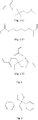
Figure 1 shows the structural formulas of non-liquid crystal compounds having photopolymerizable functional group(s), wherein:-
Figure 1-1 shows the formula of a monofunctional polymerizable monomer, (2,2,5-trimethyl)hexyl acrylate (TMHA); -
Figure 1-2 shows the formula of a bifunctional polymerizable monomer, butanediol diacrylate (BDDA); -
Figure 1-3 shows the formula of a trifunctional polymerizable monomer, trimethylolpropane triacrylate (TMPTA);
-
-
Figure 2 shows the structural formula of a photoinitiator; -
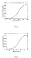
Figure 3 is a graph showing the voltage - transmittance curve of the composite prepared by the Comparative Example; -
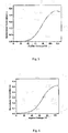
Figure 4 is a graph showing the voltage - transmittance curve of the composite prepared by Example 1; -
Figure 5 is a graph showing the voltage - transmittance curve of the composite prepared by Example 2; -
Figure 6 is a graph showing the voltage - transmittance curve of the composite prepared by Example 3; -
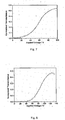
Figure 7 is a graph showing the voltage - transmittance curve of the composite prepared by Example 4; and -
Figure 8 is a graph showing the voltage - transmittance curve of the composite prepared by Example 5. - The present invention relates to a composite comprising a polymer and a blue phase liquid crystal. The polymer is a crosslinked and non-liquid crystalline polymer, and the blue phase liquid crystal is dispersed in said polymer.
- In the composite, it is preferably that the ratio of the polymer to the blue phase liquid crystal by weight (Wp/Wl) satisfies the relationship 12 : 88 < Wp/Wl ≤ 30 : 70, wherein the Wp is the weight of the polymer, and Wl is the weight of the blue phase liquid crystal. More preferably, the ratio Wp/Wl satisfies 15 : 85 ≤ Wp/Wl ≤ 25 : 75, and most preferably the ratio Wp/Wl is 20 : 80.
- The present invention also relates to a method for preparing the composite comprising a polymer and a blue phase liquid crystal. The method includes the following steps:
- blending a non-liquid crystalline compound having a photopolymerizable functional group with the blue phase liquid crystal at a ratio Wc/Wl to form a blend, wherein the Wc is the weight of the non-liquid crystalline compound, Wl is the weight of the blue phase liquid crystal; and the ratio Wc/Wl satisfies the relationship: 12 : 88 < Wc/Wl ≤ 30 : 70;
- adding a photoinitiator into the blend to form a reactive mixture; and
- while keeping the blue phase liquid crystal in the reactive mixture in the blue phase, radiating the reactive mixture with a light (preferable a UV-light) so that a polymer network is formed through a crosslinking reaction between the non-liquid crystalline compound having a photopolymerizable functional group, and thereby forming a composite comprising the polymer and the blue phase liquid crystal.
- In the present invention, the blue phase liquid crystal prefers to be a blue phase liquid crystal which exhibits a temperature range of blue phase of more than 5.0 °C, and has a viscosity of 34 to 45 mpa·s, a melting point of-20 °C to -15 °C, and a clearing point of 68 to 88 ° C.
- In the present invention, it is preferably that the ratio Wc/Wl satisfies 15 : 85 ≤ Wc/Wl ≤ 25 : 75, and more preferably the ratio Wc/Wl is 20 : 80.
- In the present invention, said non-liquid crystalline compound having a photopolymerizable functional group is a monomer for forming the polymer contained in the composite of the present invention. The monomer preferably comprises at least one multifunctional (methyl)acrylate and at least one monofunctional (methyl)acrylate, each of which is a photo-polymerizable compound.
- In the present invention, the ratio of the total monofunctional (methyl)acrylate to the total multifunctional (methyl)acrylate on a molar basis is 1:1 to 1:9, and preferably is 1:4.
- In the present invention, the term "photopolymerizable" means that the polymerizable monomer undergoes a polymerization and crosslinking reaction under the irradiation of a light, and it usually means a polymerization under the irradiation of ultraviolet (UV) light.
- In the present invention, the term "(methyl)acrylate" refers to a photopolymerizable compound having a (methyl)acryl group, preferably a (methyl)acrylate group. Herein, the term "(methyl)acrylate" means both acrylate and methacrylate. The (methyl)acrylate is a monofunctional or a multifunctional (methyl)acrylate. The multifunctional (methyl)acrylate useful in the present invention includes but is not limited to a photopolymerizable compound having 2 or 3 (methyl)acrylate groups, and for example, may be selected from the group consisting of butanediol diacrylate (BDDA), trimethylolpropane triacrylate (TMPTA), 4-[2-methyl-4-(4-acryloxylpropoxyl) benzoyloxy]phenoxycarbonyl-phenoxylpropyl acrylate and a combination thereof. The monofunctional (methyl)acrylate useful in the present invention includes but is not limited to a photopolymerizable compound having 1 (methyl)acrylate group, and for example, may be selected from the group consisting of (2,2,5-trimethyl)hexyl acrylate (TMHA), (2-ethyl)hexyl acrylate, and a combination thereof.
- In the method of the present invention, the photoinitiator is used in an amount sufficient to initiate the polymerization reaction. Usually, the amount of the photoinitiator is 0.5% to 1.5% by weight, in relative to the total amount of the non-liquid crystalline compound having a photopolymerizable functional group.
- Preferably, said photoinitiator is a UV-light initiator. With the irradiation of a UV-light, the photo-polymerizable compound (monomer) undergoes polymerization and crosslinking reaction, so as to form a polymer network, and thereby giving the composite of the present invention.
- In the method of the present invention, the irradiation can be usually carried out at a dosage of 2-10 mW/cm2, for a time period of several minutes to several hours, usually 0.5 hour or more, for example, 0.5-5h, 0.5-3h, or 0.5-1 h.
- The present invention also relates to a liquid crystal display device, which comprises a pair of substrates and the composite of the present invention. At least one of the substrates has an electrode formed thereon, and the composite is enclosed and sealed between the pair of substrates.
- The composite, the method for preparing the composite and the LCD device of the present invention will be illustrated in detail by the following Examples. But the present invention is not limited thereto.
- The BPLC used in this example consists of 82.0 wt% of SLC-X (a mixed crystal, which is a product of YongshengHuatsing Liquid Crystal Co., Ltd, Δn = 0.235, Δε = 29.6 at 298 K), 10.0 wt% of R811 and 8.0 wt% of Iso-(6OBA)2. The BPLC exhibits a temperature range of blue phase of about 10.0 °C. The chiral compound R811 and Iso-(6OBA)2 (commercially available from Merk GmbH, Germany) are represented by the following structural formulas:


- The BPLC has a viscosity of 35 mpa·s, a melting point of -15 °C, and a clearing point of 86 °C.
- The BPLC was prepared by the following procedures:
- The 82.0 wt% of SLC-X, 10.0 wt% of R811 and 8.0 wt% of Iso-(6OBA)2 were mixed together and then heated to a temperature above the clearing point (higher than the clearing point by about 5-10 °C), and maintained for about 30 minutes with sufficient agitation by a magnetic stirrer. Thus, the desired BPLC material was obtained.
- TMHA and BDDA (which structures are shown in
Figure 1 ) were employed as polymeric monomers (that is, the non-liquid crystalline compounds having photopolymerizable functional group(s)) and the ratio on a molar basis of TMHA / BDDA was 1:4. A blend was prepared by blending the polymeric monomers with the BPLC material at a mixing ratio by weight of 30:70 at room temperature. Then into the blend, a photoinitiator (which structure is shown inFigure 2 ) was added at a ratio by weight of about 1% based on the total amount of the non-liquid crystalline compounds having photopolymerizable functional group(s). Upon stirring sufficiently, a homogeneous reactive mixture was obtained. - The homogeneous reactive mixture obtained in Step 2 was injected into a liquid crystal cell by means of siphon action to prepare a sample. The liquid crystal cell is a IPS cell, with the electrode width being 5.0 micrometers, the distance between the electrodes being 5.0 micrometers, and the cell gap being maintained at 10.0 micrometers by spacers. The sample was kept on a heating stage (Linkam LK-600PM) of which the temperature was precisely controlled with an accuracy of 0.1 °C, so that the BPLC maintained in the blue phase. The sample was irradiated with a UV light at a dosage of 5 mW/cm2 for 40 minutes. The non-liquid crystalline compounds having photopolymerizable functional group(s) proceeded to perform a crosslinking reaction to form a polymer network, and thus, the composite of Example 1 was obtained.
- The BPLC texture of the composite was observed with a polarizing microscope equipped with a heating stage and the phase transition temperature was determined. The electro-optical properties of the composite were determined by a Liquid Crystal Parameters Tester (LCT-5016C, Changchun Liancheng Instrument Co. Ltd.).
- The electro-optical properties of the composite prepared according to the present invention were tested by a process described below. The test of the electro-optical properties was mainly performed to measure the electrically-induced birefringence, Δninduced , of each of the composites.
- Macroscopically, the composite of the present invention is optically isotropic when no external electric field (E) is applied. With increase of the electric field applied, the composite becomes anisotropic along the direction of the electric field. Such electrically-induced birefringence phenomenon follows the Kerr effect, that is, within a certain range of field strength, the birefringence Δninduced induced by an electric field and the electric field strength E, the detection wavelength A, and the Kerr constant K of a material satisfy the following relationship:

- In order to measure the Δninduced of the composite of the present invention, the reactive mixture prepared by Step 2 was injected by means of siphon action into a liquid crystal cell provided with in-plane electrodes (IPS cell, with the electrode width being 5.0 micrometers, the distance between the electrodes being 5.0 micrometers, and the cell gap being maintained at 10.0 micrometers by spacers). The resultant sample was oriented at an angle of 45° with respect to the direction of incident light. The temperature was precisely controlled (with an accuracy of 0.1 °C) by a heating stage (Linkam LK-600PM). To measure the electrically-induced birefringence Δninduced , a rectangular alternating current with a frequency of 60 Hz supplied by a power amplifier and a function generator was applied between the two electrodes of the IPS cell. The sample liquid crystal cell was placed between two crossed polarizers, and the intensity of the light transmitted through the liquid crystal cell was detected by a photodiode. The output intensity Iout is expressed by Equation (2):


- The composite was observed with the polarizing microscope and confirmed to have a BPLC texture. The phase transition temperature was also determined with the polarizing microscope. The composite of Example 1 was found to have a temperature range of blue phase greater than 60 °C (about from 10°C to 70°C). The electro-optical properties of the composite were measured with the Liquid Crystal Parameters Tester, and
Figure 4 shows the voltage - transmittance curve of the composite. The transmittance shown in the figure is normalized with the transmittance of the air which is 100%. The driving voltage of the composite sample is determined as the voltage corresponding to the transmittance peak in the voltage - transmittance curve. The response speed is determined as the sum of the response time during ON state and OFF state. As a result, the composite sample exhibited a driving voltage of about 110 V and a response speed of less than 1 ms. - The BPLC used in this example consists of 82.0 wt% of SLC-X (a mixed crystal, which is a product of YongshengHuatsing Liquid Crystal Co., Ltd, Δn = 0.235, Δε = 29.6 at 298 K), 10.0 wt% of R811 and 8.0 wt% of Iso-(6OBA)2. The BPLC exhibits a temperature range of blue phase of about 10.0 °C. The chiral compound R811 and Iso-(6OBA)2 (commercially available from Merk GmbH, Germany) are represented by the following structural formulas:


- The BPLC has a viscosity of 35 mPa·s, a melting point of -15 °C, and a clearing point of 86 °C.
- The BPLC was prepared by the following procedures:
- The 82.0 wt% of SLC-X, 10.0 wt% of R811 and 8.0 wt% of Iso-(6OBA)2 were mixed together and then heated to a temperature above the clearing point (higher than the clearing point by about 5-10 °C), and maintained for about 30 minutes with sufficient agitation by a magnetic stirrer. Thus, the desired BPLC material was obtained.
- TMHA and BDDA (which structures are shown in
Figure 1 ) were employed as polymeric monomers (that is, the non-liquid crystalline compounds having photopolymerizable functional group(s)) and the ratio on a molar basis of TMHA / BDDA was 1:4. A blend was prepared by blending the polymeric monomers with the BPLC material at a mixing ratio by weight of 10:90 at room temperature. Then into the blend, a photoinitiator (which structure is shown inFigure 2 ) was added at a ratio by weight of about 1% based on the total amount of the non-liquid crystalline compounds having photopolymerizable functional group(s). Upon stirring sufficiently, a homogeneous reactive mixture was obtained. - The homogeneous reactive mixture obtained in Step 2 was injected into a liquid crystal cell by means of siphon action to prepare a sample. The liquid crystal cell is a IPS cell, with the electrode width being 5.0 micrometers, the distance between the electrodes being 5.0 micrometers, and the cell gap being maintained at 10.0 micrometers by spacers. The sample was kept on a heating stage (Linkam LK-600PM) of which the temperature was precisely controlled with an accuracy of 0.1 °C, so that the BPLC maintained in the blue phase. The sample was irradiated with a UV light at a dosage of 5 mW/cm2 for 30 minutes. The non-liquid crystalline compounds having photopolymerizable functional group(s) proceeded to perform a crosslinking reaction to form a polymer network, and thus, the composite of Comparative Example was obtained.
- The resultant composite was observed with the polarizing microscope equipped with a heating stage according to the same method as described in Example 1. The composite was confirmed to have a BPLC texture and the phase transition temperature was determined. The composite of this Comparative Example was found to have a temperature range of blue phase greater than 30 °C (about from 20°C to 50 °C). The electro-optical properties of the composite were measured by a Liquid Crystal Parameters Tester according to the same method as described in Example 1, and
Figure 3 shows the voltage - transmittance curve of the composite. As a result, the composite sample exhibited a driving voltage of about 100 V and a response speed of less than 1 ms. - The BPLC used in this example consists of 60.0 wt% of SLC-1717 (a mixed crystal, which is a product of YongshengHuatsing Liquid Crystal Co., Ltd, Δn = 0.22, Δε = 12.2 at 298 K), and 40.0 wt% of R811. The BPLC exhibits a temperature range of blue phase of about 8.0 °C. The chiral compound R811 is represented by the following structural formula:

- The BPLC has a viscosity of 45 mPa·s, a melting point of -20 °C, and a clearing point of 68 °C.
- The BPLC was prepared by the following procedures:
- The 60.0 wt% of SLC-1717 and 40.0 wt% of R811 were mixed together and then heated to a temperature above the clearing point (higher than the clearing point by about 5-10 °C), and maintained for about 30 minutes with sufficient agitation by a magnetic stirrer. Thus, the desired BPLC material was obtained.
- TMHA and TMPTA (which structures are shown in
Figure 1 ) were employed as polymeric monomers (that is, the non-liquid crystalline compounds having photopolymerizable functional group(s)) and the ratio on a molar basis of TMHA / TMPTA was 1:4. A blend was prepared by blending the polymeric monomers with the BPLC material at a mixing ratio by weight of 30:70 at room temperature. Then into the blend, a photoinitiator (which structure is shown inFigure 2 ) was added at a ratio by weight of about 1% based on the total amount of the non-liquid crystalline compounds having photopolymerizable functional group(s). Upon stirring sufficiently, a homogeneous reactive mixture was obtained. - The homogeneous reactive mixture obtained in Step 2 was injected into a liquid crystal cell by means of siphon action to prepare a sample. The liquid crystal cell is a IPS cell, with the electrode width being 5.0 micrometers, the distance between the electrodes being 5.0 micrometers, and the cell gap being maintained at 10.0 micrometers by spacers. The sample was kept on a heating stage (Linkam LK-600PM) of which the temperature was precisely controlled with an accuracy of 0.1 ° C, so that the BPLC maintained in the blue phase. The sample was irradiated with a UV light at a dosage of 5 mW/cm2 for 30 minutes. The non-liquid crystalline compounds having photopolymerizable functional group(s) proceeded to perform a crosslinking reaction to form a polymer network, and thus, the composite of Example 2 was obtained.
- The resultant composite was observed with the polarizing microscope equipped with a heating stage according to the same method as described in Example 1. The composite was confirmed to have a BPLC texture and the phase transition temperature was determined. The composite of this Example was found to have a temperature range of blue phase greater than 70 °C (about from 5 °C to 75 °C). The electro-optical properties of the composite were measured by a Liquid Crystal Parameters Tester according to the same method as described in Example 1, and
Figure 5 shows the voltage - transmittance curve of the composite. As a result, the composite sample exhibited a driving voltage of about 120 V and a response speed of less than 1 ms. - The BPLC used in this example consists of 92.0 wt% of SLC-X (a mixed crystal, which is a product of YongshengHuatsing Liquid Crystal Co., Ltd, Δn = 0.235, Δε = 29.6 at 298 K), and 8.0 wt% of Iso-(6OBA)2. The BPLC exhibits a temperature range of blue phase of about 5.0 °C.
- The BPLC has a viscosity of 34 mPa·s, a melting point of -16 °C, and a clearing point of 88 °C.
- The BPLC was prepared by the following procedures:
- The 92.0 wt% of SLC-X and 8.0 wt% of Iso-(6OBA)2 were mixed together and then heated to a temperature above the clearing point (higher than the clearing point by about 5-10 °C), and maintained for about 30 minutes with sufficient agitation by a magnetic stirrer. Thus, the desired BPLC material was obtained.
- TMHA, BDDA and TMPTA (which structures are shown in
Figure 1 ) were employed as polymeric monomers (that is, the non-liquid crystalline compounds having photopolymerizable functional group(s)) and the ratio on a molar basis of TMHA / BDDA / TMPTA was 1:2:3. A blend was prepared by blending the polymeric monomers with the BPLC material at a mixing ratio by weight of 20:80 at room temperature. Then into the blend, a photoinitiator (which structure is shown inFigure 2 ) was added at a ratio by weight of about 1% based on the total amount of the non-liquid crystalline compounds having photopolymerizable functional group(s). Upon stirring sufficiently, a homogeneous reactive mixture was obtained. - The homogeneous reactive mixture obtained in Step 2 was injected into a liquid crystal cell by means of siphon action to prepare a sample. The liquid crystal cell is a IPS cell, with the electrode width being 5.0 micrometers, the distance between the electrodes being 5.0 micrometers, and the cell gap being maintained at 10.0 micrometers by spacers. The sample was kept on a heating stage (Linkam LK-600PM) of which the temperature was precisely controlled with an accuracy of 0.1 °C, so that the BPLC maintained in the blue phase. The sample was irradiated with a UV light at a dosage of 5 mW/cm2 for 30 minutes. The non-liquid crystalline compounds having photopolymerizable functional group(s) proceeded to perform a crosslinking reaction to form a polymer network, and thus, the composite of Example 3 was obtained.
- The resultant composite was observed with the polarizing microscope equipped with a heating stage according to the same method as described in Example 1. The composite was confirmed to have a BPLC texture and the phase transition temperature was determined. The composite of this Example was found to have a temperature range of blue phase greater than 60 °C (about from 10 °C to 70 ° C). The electro-optical properties of the composite were measured by a Liquid Crystal Parameters Tester according to the same method as described in Example 1, and
Figure 6 shows the voltage - transmittance curve of the composite. As a result, the composite sample exhibited a driving voltage of about 105 V and a response speed of less than 1 ms. - The BPLC used in this example consists of 92.0 wt% of SLC-X (a mixed crystal, which is a product of YongshengHuatsing Liquid Crystal Co., Ltd, Δn = 0.235, Δε = 29.6 at 298 K), and 8.0 wt% of Iso-(6OBA)2. The BPLC exhibits a temperature range of blue phase of about 5.0 °C.
- The BPLC has a viscosity of 34 mpa·s, a melting point of -16 °C, and a clearing point of 88 °C.
- The BPLC was prepared by the following procedures:
- The 92.0 wt% of SLC-X and 8.0 wt% of Iso-(6OBA)2 were mixed together and then heated to a temperature above the clearing point (higher than the clearing point by about 5-10 °C), and maintained for about 30 minutes with sufficient agitation by a magnetic stirrer. Thus, the desired BPLC material was obtained.
- TMHA, BDDA and TMPTA (which structures are shown in
Figure 1 ) were employed as polymeric monomers (that is, the non-liquid crystalline compounds having photopolymerizable functional group(s)) and the ratio on a molar basis of TMHA / BDDA / TMPTA was 2:1:1. A blend was prepared by blending the polymeric monomers with the BPLC material at a mixing ratio by weight of 20:80 at room temperature. Then into the blend, a photoinitiator (which structure is shown inFigure 2 ) was added at a ratio by weight of about 1% based on the total amount of the non-liquid crystalline compounds having photopolymerizable functional group(s). Upon stirring sufficiently, a homogeneous reactive mixture was obtained. - The homogeneous reactive mixture obtained in Step 2 was injected into a liquid crystal cell by means of siphon action to prepare a sample. The liquid crystal cell is a IPS cell, with the electrode width being 5.0 micrometers, the distance between the electrodes being 5.0 micrometers, and the cell gap being maintained at 10.0 micrometers by spacers. The sample was kept on a heating stage (Linkam LK-600PM) of which the temperature was precisely controlled with an accuracy of 0.1 °C, so that the BPLC maintained in the blue phase. The sample was irradiated with a UV light at a dosage of 5 mW/cm2 for 30 minutes. The non-liquid crystalline compounds having photopolymerizable functional group(s) proceeded to perform a crosslinking reaction to form a polymer network, and thus, the composite of Example 4 was obtained.
- The resultant composite was observed with the polarizing microscope equipped with a heating stage according to the same method as described in Example 1. The composite was confirmed to have a BPLC texture and the phase transition temperature was determined. The composite of this Example was found to have a temperature range of blue phase greater than 60 °C (about from 10 °C to 70 °C). The electro-optical properties of the composite were measured by a Liquid Crystal Parameters Tester according to the same method as described in Example 1, and
Figure 7 shows the voltage - transmittance curve of the composite. As a result, the composite sample exhibited a driving voltage of about 100 V and a response speed of less than 1 ms. - The BPLC used in this example consists of 92.0 wt% of SLC-X (a mixed crystal, which is a product of YongshengHuatsing Liquid Crystal Co., Ltd, Δn = 0.235, Δε = 29.6 at 298 K), and 8.0 wt% of Iso-(6OBA)2. The BPLC exhibits a temperature range of blue phase of about 5.0 °C.
- The BPLC has a viscosity of 34 mPa·s, a melting point of -16 °C, and a clearing point of 88 °C.
- The BPLC was prepared by the following procedures:
- The 92.0 wt% of SLC-X and 8.0 wt% of Iso-(6OBA)2 were mixed together and then heated to a temperature above the clearing point (higher than the clearing point by about 5-10 °C), and maintained for about 30 minutes with sufficient agitation by a magnetic stirrer. Thus, the desired BPLC material was obtained.
- TMHA, BDDA and TMPTA (which structures are shown in
Figure 1 ) were employed as polymeric monomers (that is, the non-liquid crystalline compounds having photopolymerizable functional group(s)) and the ratio on a molar basis of TMHA / BDDA / TMPTA was 1:4:5. A blend was prepared by blending the polymeric monomers with the BPLC material at a mixing ratio by weight of 20:80 at room temperature. Then into the blend, a photoinitiator (which structure is shown inFigure 2 ) was added at a ratio by weight of about 1% based on the total amount of the non-liquid crystalline compounds having photopolymerizable functional group(s). Upon stirring sufficiently, a homogeneous reactive mixture was obtained. - The homogeneous reactive mixture obtained in Step 2 was injected into a liquid crystal cell by means of siphon action to prepare a sample. The liquid crystal cell is a IPS cell, with the electrode width being 5.0 micrometers, the distance between the electrodes being 5.0 micrometers, and the cell gap being maintained at 10.0 micrometers by spacers. The sample was kept on a heating stage (Linkam LK-600PM) of which the temperature was precisely controlled with an accuracy of 0.1 °C, so that the BPLC maintained in the blue phase. The sample was irradiated with a UV light at a dosage of 5 mW/cm2 for 30 minutes. The non-liquid crystal compounds having photopolymerizable functional group(s) proceeded to perform a crosslinking reaction to form a polymer network, and thus, the composite of Example 5 was obtained.
- The resultant composite was observed with the polarizing microscope equipped with a heating stage according to the same method as described in Example 1. The composite was confirmed to have a BPLC texture and the phase transition temperature was determined. The composite of this Example was found to have a temperature range of blue phase greater than 70 °C (about from 5°C to 75 °C). The electro-optical properties of the composite were measured by a Liquid Crystal Parameters Tester according to the same method as described in Example 1, and
Figure 8 shows the voltage - transmittance curve of the composite. As a result, the composite sample exhibited a driving voltage of about 130 V and a response speed of less than 1 ms. - The Examples described above reveal that the method of the present invention can provide a composite comprising a polymer and a BPLC, which exhibits a very wide temperature range of blue phase, and has a fast response speed to the electrical filed (at a sub-millisecond level), a lower driving voltage as well as a good stability in the wide temperature range. Since the viscosity of the mixed crystal is low, the BPLC can be easily dispersed in the polymer network. Therefore, based on the method of the present invention, it is possible to develop a liquid crystal product having a large size and high homogeneity. In addition, the composite prepared by the present invention may have a higher polymer content, as compared with the known polymer-stabilized BPLC composite material. Thus, the deformation of the polymer network under an electrical filed can be effectively prevented, and the microstructure of the polymer network can be precisely controlled by adjusting the monomers of the polymer.
- The present invention further provides a liquid crystal display device, which comprises a pair of substrates wherein at least one of the substrates has an electrode formed thereon; and the composite being enclosed and sealed between the substrates. The display device may be a liquid crystal panel, or any product or a part thereof having a function of displaying, for example, a mobile phone, a tablet PC, a television, a display, a notebook computer, a digital picture frames, navigator and the like.
Claims (15)
- A composite comprising a polymer and a blue phase liquid crystal, characterized in that the polymer is a crosslinked and non-liquid crystalline polymer, the blue phase liquid crystal is dispersed in said polymer, and the ratio of the polymer to the blue phase liquid crystal by weight (Wp/Wl) satisfies the following relationship:

- The composite according to claim 1, characterized in that the ratio of the polymer to the blue phase liquid crystal by weight (Wp/Ml) satisfies the following relationship:

- The composite according to claim 2, characterized in that the ratio of the polymer to the blue phase liquid crystal by weight (Wp/Wl) is 20 : 80.
- The composite according to claim 1, characterized in that the polymer is derived from monomers comprising at least one photo-polymerizable multifunctional (methyl)acrylate and at least one photo-polymerizable monofunctional (methyl)acrylate.
- The composite according to claim 4, characterized in that
the multifunctional (methyl)acrylate is selected from the group consisting of butanediol diacrylate (BDDA), trimethylolpropane triacrylate (TMPTA), 4-[2-methyl-4-(4-acryloxylpropoxyl)benzoyloxy]phenoxycarbonyl-phenoxylpropyl acrylate and a combination thereof; and
the monofunctional (methyl)acrylate is selected from the group consisting of (2,2,5-trimethyl)hexyl acrylate (TMHA), 2-ethylhexyl acrylate and a combination thereof. - The composite according to claim 4, characterized in that
the ratio of the total monofunctional (methyl)acrylate to the total multifunctional (methyl)acrylate on a molar basis is 1:1 to 1:9. - The composite according to claim 6, characterized in that
the ratio of the total monofunctional (methyl)acrylate to the total multifunctional (methyl)acrylate on a molar basis is 1:4. - A method for preparing a composite comprising a polymer and a blue phase liquid crystal, including the following steps:blending a non-liquid crystalline compound having a photopolymerizable functional group with the blue phase liquid crystal at a ratio Wc/Wl to form a blend, wherein the Wc is the weight of the non-liquid crystalline compound, Wl is the weight of the blue phase liquid crystal; and the ratio Wc/Wl satisfies the relationship: 12 : 88 < Wc/Wl ≤ 30 : 70;adding a photoinitiator into the blend to form a reactive mixture; andwhile keeping the blue phase liquid crystal in the reactive mixture in the blue phase, radiating the reactive mixture with a light so that a polymer network is formed through a crosslinking reaction between the non-liquid crystalline compound having a photopolymerizable functional group, and thereby forming a composite comprising the polymer and the blue phase liquid crystal.
- The method according to claim 8, characterized in that
the blue phase liquid crystal exhibits a temperature range of blue phase of more than 5.0 °C, and has a viscosity of 34 to 45 mpa·s, a melting point of -20 °C to -15 °C, and a clearing point of 68 to 88 °C. - The method according to claim 8, characterized in that
the ratio Wc/Wl satisfies the relationship: 15 : 85 ≤ WcWl ≤ 25 : 75. - The method according to claim 10, characterized in that
the ratio Wc/Wl is 20 : 80. - The method according to claim 8, characterized in that
the non-liquid crystalline compound having a photopolymerizable functional group comprises at least one multifunctional (methyl)acrylate and at least one monofunctional (methyl)acrylate. - The method according to claim 12, characterized in that
the multifunctional (methyl)acrylate is selected from the group consisting of butanediol diacrylate (BDDA), trimethylolpropane triacrylate (TMPTA), 4-[2-methyl-4-(4-acryloxylpropoxyl) benzoyloxy]phenoxycarbonyl-phenoxylpropyl acrylate and a combination thereof; and
the monofunctional (methyl)acrylate is selected from the group consisting of (2,2,5-trimethyl)hexyl acrylate (TMHA), (2-ethyl)hexyl acrylate, and a combination thereof. - The method according to claim 12, characterized in that
among the non-liquid crystalline compound having a photopolymerizable functional group, the ratio of the total monofunctional (methyl)acrylate to the total multifunctional (methyl)acrylate on a molar basis is 1:1 to 1:9. - The method according to claim 14, characterized in that
among the non-liquid crystalline compound having a photopolymerizable functional group, the ratio of the total monofunctional (methyl)acrylate to the total multifunctional (methyl)acrylate on a molar basis is 1:4.
Applications Claiming Priority (1)
| Application Number | Priority Date | Filing Date | Title |
|---|---|---|---|
| CN201210409249.9A CN102952551B (en) | 2012-10-24 | 2012-10-24 | Polymer dispersed blue-phase liquid crystal material and preparation method thereof as well as liquid crystal display device |
Publications (3)
| Publication Number | Publication Date |
|---|---|
| EP2725085A2 EP2725085A2 (en) | 2014-04-30 |
| EP2725085A3 EP2725085A3 (en) | 2014-10-29 |
| EP2725085B1 true EP2725085B1 (en) | 2018-02-28 |
Family
ID=47761948
Family Applications (1)
| Application Number | Title | Priority Date | Filing Date |
|---|---|---|---|
| EP13188885.1A Active EP2725085B1 (en) | 2012-10-24 | 2013-10-16 | A composite comprising a polymer and a blue phase liquid crystal, a method for preparing the composite, and a liquid crystal display device comprising the composite |
Country Status (5)
| Country | Link |
|---|---|
| US (1) | US9139776B2 (en) |
| EP (1) | EP2725085B1 (en) |
| JP (1) | JP6309239B2 (en) |
| KR (1) | KR101531103B1 (en) |
| CN (1) | CN102952551B (en) |
Families Citing this family (9)
| Publication number | Priority date | Publication date | Assignee | Title |
|---|---|---|---|---|
| CN103215050A (en) * | 2013-03-28 | 2013-07-24 | 京东方科技集团股份有限公司 | Blue-phase liquid crystal composite material and liquid crystal display comprising same |
| US9273248B2 (en) | 2013-03-28 | 2016-03-01 | Boe Technology Group Co., Ltd. | Blue phase liquid crystal composite material and liquid crystal display containing the same |
| CN105392864B (en) * | 2013-04-28 | 2017-10-27 | 华东理工大学 | Polymer stabilizing double frequency blue phase liquid crystal |
| CN103499900B (en) * | 2013-09-02 | 2015-11-11 | 京东方科技集团股份有限公司 | Liquid crystal panel and preparation method thereof, display |
| EP3115436A1 (en) * | 2015-07-08 | 2017-01-11 | Essilor International (Compagnie Generale D'optique) | Method for obtaining a material comprising a liquid crystal mix with a stabilized blue phase and optical article comprising this material |
| KR101972789B1 (en) | 2017-04-10 | 2019-04-26 | 경희대학교 산학협력단 | Blue phase liquid crystal composition and photo control device comprising the same |
| CN107632465B (en) * | 2017-10-16 | 2021-03-23 | 京东方科技集团股份有限公司 | Liquid crystal display panel and preparation method thereof |
| CN110358549B (en) * | 2018-03-26 | 2020-10-30 | 中国科学院理化技术研究所 | Blue phase liquid crystal composite material |
| CN113625380A (en) * | 2021-05-27 | 2021-11-09 | 邓景月 | Grating preparation method and ARPDLC holographic polymer liquid crystal grating |
Family Cites Families (23)
| Publication number | Priority date | Publication date | Assignee | Title |
|---|---|---|---|---|
| JPH06148603A (en) * | 1992-11-12 | 1994-05-27 | Mitsubishi Kasei Corp | Method of manufacturing light control material and light control element |
| JPH07159749A (en) * | 1993-12-06 | 1995-06-23 | Matsushita Electric Ind Co Ltd | Liquid crystal display device |
| JP3779937B2 (en) * | 2002-05-08 | 2006-05-31 | 独立行政法人科学技術振興機構 | Liquid crystal material for optical modulator |
| GB0402006D0 (en) * | 2004-01-30 | 2004-03-03 | Dow Corning Ltd | Liquid crystal materials |
| JP5269284B2 (en) * | 2004-04-30 | 2013-08-21 | 独立行政法人科学技術振興機構 | Composite material comprising polymer and liquid crystal material having chirality, method for producing the composite material, and optical element using the composite material |
| JP2006348226A (en) * | 2005-06-17 | 2006-12-28 | Asahi Glass Co Ltd | Liquid crystal / polymer composite |
| JP5875032B2 (en) * | 2007-05-08 | 2016-03-02 | 国立大学法人九州大学 | Polymer / liquid crystal composite material and liquid crystal element |
| US7648647B2 (en) * | 2007-05-08 | 2010-01-19 | Kyushu University, National University Corporation | Polymer/liquid crystal composite and liquid crystal element |
| JP5487398B2 (en) * | 2007-08-31 | 2014-05-07 | 国立大学法人九州大学 | Liquid crystal composition and liquid crystal element |
| KR101479996B1 (en) * | 2008-02-21 | 2015-01-08 | 삼성디스플레이 주식회사 | Method for manufacturing display device |
| JP5420989B2 (en) * | 2008-06-25 | 2014-02-19 | 富士フイルム株式会社 | Liquid crystal display |
| KR101472082B1 (en) * | 2008-10-10 | 2014-12-16 | 삼성디스플레이 주식회사 | Liquid crystal display and method of fabricating the same |
| WO2011089653A1 (en) * | 2010-01-25 | 2011-07-28 | 株式会社 東芝 | Liquid crystal/polymer composite, liquid crystal display device using the same, and method for producing liquid crystal/polymer composite |
| US8471814B2 (en) * | 2010-02-26 | 2013-06-25 | Microsoft Corporation | User interface control using a keyboard |
| JP5379053B2 (en) * | 2010-03-26 | 2013-12-25 | スタンレー電気株式会社 | Optical deflection device |
| US8501284B2 (en) * | 2010-03-31 | 2013-08-06 | Sony Corporation | Blue phase liquid crystal composition |
| US20130070193A1 (en) * | 2010-03-31 | 2013-03-21 | Sony Corporation | Method of stabilizing a blue phase liquid crystal composition |
| US8928846B2 (en) * | 2010-05-21 | 2015-01-06 | Semiconductor Energy Laboratory Co., Ltd. | Liquid crystal display device having dielectric film over and in contact with wall-like structures |
| US8801964B2 (en) * | 2010-12-22 | 2014-08-12 | Photon Dynamics, Inc. | Encapsulated polymer network liquid crystal material, device and applications |
| US8568614B2 (en) * | 2011-03-18 | 2013-10-29 | Sony Corporation | Blue phase liquid crystal composition with reduced hysteresis behavior |
| CN102517040B (en) * | 2011-12-15 | 2013-09-25 | 昆山龙腾光电有限公司 | Blue phase liquid crystal material formulation, blue phase liquid crystal material and production method thereof |
| TWI496874B (en) * | 2012-06-26 | 2015-08-21 | Ind Tech Res Inst | Polymer-stabilized optically isotropic liquid crystal formulation and optical device |
| TWI472854B (en) * | 2012-06-27 | 2015-02-11 | 友達光電股份有限公司 | Blue phase liquid crystal display panel and manufacturing method thereof |
-
2012
- 2012-10-24 CN CN201210409249.9A patent/CN102952551B/en active Active
-
2013
- 2013-10-16 EP EP13188885.1A patent/EP2725085B1/en active Active
- 2013-10-18 KR KR1020130124438A patent/KR101531103B1/en active Active
- 2013-10-21 US US14/058,662 patent/US9139776B2/en active Active
- 2013-10-23 JP JP2013219945A patent/JP6309239B2/en active Active
Non-Patent Citations (1)
| Title |
|---|
| None * |
Also Published As
| Publication number | Publication date |
|---|---|
| JP2014085675A (en) | 2014-05-12 |
| US9139776B2 (en) | 2015-09-22 |
| CN102952551A (en) | 2013-03-06 |
| EP2725085A2 (en) | 2014-04-30 |
| KR101531103B1 (en) | 2015-06-23 |
| EP2725085A3 (en) | 2014-10-29 |
| US20140111759A1 (en) | 2014-04-24 |
| JP6309239B2 (en) | 2018-04-11 |
| CN102952551B (en) | 2014-10-22 |
Similar Documents
| Publication | Publication Date | Title |
|---|---|---|
| US9139776B2 (en) | Composite comprising a polymer and a blue phase liquid crystal, a method for preparing the composite, and a liquid crystal display device comprising the composite | |
| KR102666065B1 (en) | Liquid crystal composition and liquid crystal display element | |
| JP4766694B2 (en) | Liquid crystal display element | |
| KR102666064B1 (en) | Liquid crystal composition and liquid crystal display element | |
| EP2360229B1 (en) | Optically isotropic liquid crystal medium and optical element | |
| EP2894148B1 (en) | Novel smectic phase a liquid crystal material | |
| TWI597353B (en) | Liquid-crystal display | |
| JP3779937B2 (en) | Liquid crystal material for optical modulator | |
| CN102786936B (en) | Liquid crystal medium composition | |
| Manda et al. | Self-supported liquid crystal film for flexible display and photonic applications | |
| TW200422715A (en) | Liquid crystal display and method of manufacturing the same | |
| JPWO2006025234A1 (en) | Display element and display device | |
| CN106281361B (en) | Polymer network liquid crystal display | |
| JPWO2018025996A1 (en) | Material for liquid crystal device and liquid crystal device | |
| JP2019137753A (en) | Liquid crystal composition and liquid crystal display | |
| KR20160003063A (en) | Polymerizable mixture and liquid crystal composition thereof | |
| CN112175634A (en) | Polymer stable alignment type liquid crystal composition and application thereof | |
| CN108342196A (en) | Liquid crystal composition and liquid crystal display element or liquid crystal display comprising the liquid crystal composition | |
| Zheng et al. | Dichroic-dye-doped polymer stabilized optically isotropic chiral liquid crystals | |
| TWI614331B (en) | Dichroic-dye-doped isotropic chiral liquid crystals | |
| Cui et al. | Photo-driven liquid crystal cell with high sensitivity | |
| CN105331370B (en) | Negative liquid crystal composition and its application | |
| CN102533278B (en) | Liquid crystal composition | |
| Park et al. | Fast switching of vertically aligned liquid crystals by low-temperature curing of the polymer structure | |
| Chen et al. | Fast-response liquid crystal display by the VA-IPS display mode with nematic liquid crystal and polymer networks |
Legal Events
| Date | Code | Title | Description |
|---|---|---|---|
| PUAI | Public reference made under article 153(3) epc to a published international application that has entered the european phase |
Free format text: ORIGINAL CODE: 0009012 |
|
| 17P | Request for examination filed |
Effective date: 20131016 |
|
| AK | Designated contracting states |
Kind code of ref document: A2 Designated state(s): AL AT BE BG CH CY CZ DE DK EE ES FI FR GB GR HR HU IE IS IT LI LT LU LV MC MK MT NL NO PL PT RO RS SE SI SK SM TR |
|
| AX | Request for extension of the european patent |
Extension state: BA ME |
|
| PUAL | Search report despatched |
Free format text: ORIGINAL CODE: 0009013 |
|
| AK | Designated contracting states |
Kind code of ref document: A3 Designated state(s): AL AT BE BG CH CY CZ DE DK EE ES FI FR GB GR HR HU IE IS IT LI LT LU LV MC MK MT NL NO PL PT RO RS SE SI SK SM TR |
|
| AX | Request for extension of the european patent |
Extension state: BA ME |
|
| RIC1 | Information provided on ipc code assigned before grant |
Ipc: C09K 19/02 20060101ALI20140922BHEP Ipc: C09K 19/54 20060101AFI20140922BHEP |
|
| 17P | Request for examination filed |
Effective date: 20141210 |
|
| RBV | Designated contracting states (corrected) |
Designated state(s): AL AT BE BG CH CY CZ DE DK EE ES FI FR GB GR HR HU IE IS IT LI LT LU LV MC MK MT NL NO PL PT RO RS SE SI SK SM TR |
|
| 17Q | First examination report despatched |
Effective date: 20160629 |
|
| GRAP | Despatch of communication of intention to grant a patent |
Free format text: ORIGINAL CODE: EPIDOSNIGR1 |
|
| INTG | Intention to grant announced |
Effective date: 20170908 |
|
| RIC1 | Information provided on ipc code assigned before grant |
Ipc: C09K 19/54 20060101AFI20170825BHEP Ipc: C09K 19/02 20060101ALI20170825BHEP Ipc: C09K 19/52 20060101ALI20170825BHEP |
|
| GRAS | Grant fee paid |
Free format text: ORIGINAL CODE: EPIDOSNIGR3 |
|
| GRAA | (expected) grant |
Free format text: ORIGINAL CODE: 0009210 |
|
| AK | Designated contracting states |
Kind code of ref document: B1 Designated state(s): AL AT BE BG CH CY CZ DE DK EE ES FI FR GB GR HR HU IE IS IT LI LT LU LV MC MK MT NL NO PL PT RO RS SE SI SK SM TR |
|
| REG | Reference to a national code |
Ref country code: GB Ref legal event code: FG4D Ref country code: CH Ref legal event code: EP |
|
| REG | Reference to a national code |
Ref country code: AT Ref legal event code: REF Ref document number: 974116 Country of ref document: AT Kind code of ref document: T Effective date: 20180315 |
|
| REG | Reference to a national code |
Ref country code: IE Ref legal event code: FG4D |
|
| REG | Reference to a national code |
Ref country code: DE Ref legal event code: R096 Ref document number: 602013033646 Country of ref document: DE |
|
| REG | Reference to a national code |
Ref country code: NL Ref legal event code: FP |
|
| REG | Reference to a national code |
Ref country code: LT Ref legal event code: MG4D |
|
| REG | Reference to a national code |
Ref country code: AT Ref legal event code: MK05 Ref document number: 974116 Country of ref document: AT Kind code of ref document: T Effective date: 20180228 |
|
| PG25 | Lapsed in a contracting state [announced via postgrant information from national office to epo] |
Ref country code: LT Free format text: LAPSE BECAUSE OF FAILURE TO SUBMIT A TRANSLATION OF THE DESCRIPTION OR TO PAY THE FEE WITHIN THE PRESCRIBED TIME-LIMIT Effective date: 20180228 Ref country code: ES Free format text: LAPSE BECAUSE OF FAILURE TO SUBMIT A TRANSLATION OF THE DESCRIPTION OR TO PAY THE FEE WITHIN THE PRESCRIBED TIME-LIMIT Effective date: 20180228 Ref country code: CY Free format text: LAPSE BECAUSE OF FAILURE TO SUBMIT A TRANSLATION OF THE DESCRIPTION OR TO PAY THE FEE WITHIN THE PRESCRIBED TIME-LIMIT Effective date: 20180228 Ref country code: FI Free format text: LAPSE BECAUSE OF FAILURE TO SUBMIT A TRANSLATION OF THE DESCRIPTION OR TO PAY THE FEE WITHIN THE PRESCRIBED TIME-LIMIT Effective date: 20180228 Ref country code: NO Free format text: LAPSE BECAUSE OF FAILURE TO SUBMIT A TRANSLATION OF THE DESCRIPTION OR TO PAY THE FEE WITHIN THE PRESCRIBED TIME-LIMIT Effective date: 20180528 Ref country code: HR Free format text: LAPSE BECAUSE OF FAILURE TO SUBMIT A TRANSLATION OF THE DESCRIPTION OR TO PAY THE FEE WITHIN THE PRESCRIBED TIME-LIMIT Effective date: 20180228 |
|
| PG25 | Lapsed in a contracting state [announced via postgrant information from national office to epo] |
Ref country code: LV Free format text: LAPSE BECAUSE OF FAILURE TO SUBMIT A TRANSLATION OF THE DESCRIPTION OR TO PAY THE FEE WITHIN THE PRESCRIBED TIME-LIMIT Effective date: 20180228 Ref country code: SE Free format text: LAPSE BECAUSE OF FAILURE TO SUBMIT A TRANSLATION OF THE DESCRIPTION OR TO PAY THE FEE WITHIN THE PRESCRIBED TIME-LIMIT Effective date: 20180228 Ref country code: RS Free format text: LAPSE BECAUSE OF FAILURE TO SUBMIT A TRANSLATION OF THE DESCRIPTION OR TO PAY THE FEE WITHIN THE PRESCRIBED TIME-LIMIT Effective date: 20180228 Ref country code: AT Free format text: LAPSE BECAUSE OF FAILURE TO SUBMIT A TRANSLATION OF THE DESCRIPTION OR TO PAY THE FEE WITHIN THE PRESCRIBED TIME-LIMIT Effective date: 20180228 Ref country code: BG Free format text: LAPSE BECAUSE OF FAILURE TO SUBMIT A TRANSLATION OF THE DESCRIPTION OR TO PAY THE FEE WITHIN THE PRESCRIBED TIME-LIMIT Effective date: 20180528 Ref country code: GR Free format text: LAPSE BECAUSE OF FAILURE TO SUBMIT A TRANSLATION OF THE DESCRIPTION OR TO PAY THE FEE WITHIN THE PRESCRIBED TIME-LIMIT Effective date: 20180529 |
|
| REG | Reference to a national code |
Ref country code: FR Ref legal event code: PLFP Year of fee payment: 6 |
|
| PG25 | Lapsed in a contracting state [announced via postgrant information from national office to epo] |
Ref country code: AL Free format text: LAPSE BECAUSE OF FAILURE TO SUBMIT A TRANSLATION OF THE DESCRIPTION OR TO PAY THE FEE WITHIN THE PRESCRIBED TIME-LIMIT Effective date: 20180228 Ref country code: RO Free format text: LAPSE BECAUSE OF FAILURE TO SUBMIT A TRANSLATION OF THE DESCRIPTION OR TO PAY THE FEE WITHIN THE PRESCRIBED TIME-LIMIT Effective date: 20180228 Ref country code: EE Free format text: LAPSE BECAUSE OF FAILURE TO SUBMIT A TRANSLATION OF THE DESCRIPTION OR TO PAY THE FEE WITHIN THE PRESCRIBED TIME-LIMIT Effective date: 20180228 Ref country code: PL Free format text: LAPSE BECAUSE OF FAILURE TO SUBMIT A TRANSLATION OF THE DESCRIPTION OR TO PAY THE FEE WITHIN THE PRESCRIBED TIME-LIMIT Effective date: 20180228 Ref country code: IT Free format text: LAPSE BECAUSE OF FAILURE TO SUBMIT A TRANSLATION OF THE DESCRIPTION OR TO PAY THE FEE WITHIN THE PRESCRIBED TIME-LIMIT Effective date: 20180228 |
|
| REG | Reference to a national code |
Ref country code: DE Ref legal event code: R097 Ref document number: 602013033646 Country of ref document: DE |
|
| PG25 | Lapsed in a contracting state [announced via postgrant information from national office to epo] |
Ref country code: SM Free format text: LAPSE BECAUSE OF FAILURE TO SUBMIT A TRANSLATION OF THE DESCRIPTION OR TO PAY THE FEE WITHIN THE PRESCRIBED TIME-LIMIT Effective date: 20180228 Ref country code: SK Free format text: LAPSE BECAUSE OF FAILURE TO SUBMIT A TRANSLATION OF THE DESCRIPTION OR TO PAY THE FEE WITHIN THE PRESCRIBED TIME-LIMIT Effective date: 20180228 Ref country code: DK Free format text: LAPSE BECAUSE OF FAILURE TO SUBMIT A TRANSLATION OF THE DESCRIPTION OR TO PAY THE FEE WITHIN THE PRESCRIBED TIME-LIMIT Effective date: 20180228 Ref country code: CZ Free format text: LAPSE BECAUSE OF FAILURE TO SUBMIT A TRANSLATION OF THE DESCRIPTION OR TO PAY THE FEE WITHIN THE PRESCRIBED TIME-LIMIT Effective date: 20180228 |
|
| PLBE | No opposition filed within time limit |
Free format text: ORIGINAL CODE: 0009261 |
|
| STAA | Information on the status of an ep patent application or granted ep patent |
Free format text: STATUS: NO OPPOSITION FILED WITHIN TIME LIMIT |
|
| 26N | No opposition filed |
Effective date: 20181129 |
|
| PG25 | Lapsed in a contracting state [announced via postgrant information from national office to epo] |
Ref country code: SI Free format text: LAPSE BECAUSE OF FAILURE TO SUBMIT A TRANSLATION OF THE DESCRIPTION OR TO PAY THE FEE WITHIN THE PRESCRIBED TIME-LIMIT Effective date: 20180228 |
|
| REG | Reference to a national code |
Ref country code: CH Ref legal event code: PL |
|
| REG | Reference to a national code |
Ref country code: BE Ref legal event code: MM Effective date: 20181031 |
|
| PG25 | Lapsed in a contracting state [announced via postgrant information from national office to epo] |
Ref country code: MC Free format text: LAPSE BECAUSE OF FAILURE TO SUBMIT A TRANSLATION OF THE DESCRIPTION OR TO PAY THE FEE WITHIN THE PRESCRIBED TIME-LIMIT Effective date: 20180228 Ref country code: LU Free format text: LAPSE BECAUSE OF NON-PAYMENT OF DUE FEES Effective date: 20181016 |
|
| REG | Reference to a national code |
Ref country code: IE Ref legal event code: MM4A |
|
| PG25 | Lapsed in a contracting state [announced via postgrant information from national office to epo] |
Ref country code: BE Free format text: LAPSE BECAUSE OF NON-PAYMENT OF DUE FEES Effective date: 20181031 Ref country code: LI Free format text: LAPSE BECAUSE OF NON-PAYMENT OF DUE FEES Effective date: 20181031 Ref country code: CH Free format text: LAPSE BECAUSE OF NON-PAYMENT OF DUE FEES Effective date: 20181031 |
|
| PG25 | Lapsed in a contracting state [announced via postgrant information from national office to epo] |
Ref country code: IE Free format text: LAPSE BECAUSE OF NON-PAYMENT OF DUE FEES Effective date: 20181016 |
|
| PG25 | Lapsed in a contracting state [announced via postgrant information from national office to epo] |
Ref country code: MT Free format text: LAPSE BECAUSE OF NON-PAYMENT OF DUE FEES Effective date: 20181016 |
|
| PG25 | Lapsed in a contracting state [announced via postgrant information from national office to epo] |
Ref country code: TR Free format text: LAPSE BECAUSE OF FAILURE TO SUBMIT A TRANSLATION OF THE DESCRIPTION OR TO PAY THE FEE WITHIN THE PRESCRIBED TIME-LIMIT Effective date: 20180228 |
|
| PG25 | Lapsed in a contracting state [announced via postgrant information from national office to epo] |
Ref country code: PT Free format text: LAPSE BECAUSE OF FAILURE TO SUBMIT A TRANSLATION OF THE DESCRIPTION OR TO PAY THE FEE WITHIN THE PRESCRIBED TIME-LIMIT Effective date: 20180228 |
|
| PG25 | Lapsed in a contracting state [announced via postgrant information from national office to epo] |
Ref country code: HU Free format text: LAPSE BECAUSE OF FAILURE TO SUBMIT A TRANSLATION OF THE DESCRIPTION OR TO PAY THE FEE WITHIN THE PRESCRIBED TIME-LIMIT; INVALID AB INITIO Effective date: 20131016 Ref country code: MK Free format text: LAPSE BECAUSE OF NON-PAYMENT OF DUE FEES Effective date: 20180228 |
|
| PG25 | Lapsed in a contracting state [announced via postgrant information from national office to epo] |
Ref country code: IS Free format text: LAPSE BECAUSE OF FAILURE TO SUBMIT A TRANSLATION OF THE DESCRIPTION OR TO PAY THE FEE WITHIN THE PRESCRIBED TIME-LIMIT Effective date: 20180628 |
|
| P01 | Opt-out of the competence of the unified patent court (upc) registered |
Effective date: 20230630 |
|
| PGFP | Annual fee paid to national office [announced via postgrant information from national office to epo] |
Ref country code: NL Payment date: 20250814 Year of fee payment: 13 |
|
| PGFP | Annual fee paid to national office [announced via postgrant information from national office to epo] |
Ref country code: GB Payment date: 20250828 Year of fee payment: 13 |
|
| PGFP | Annual fee paid to national office [announced via postgrant information from national office to epo] |
Ref country code: FR Payment date: 20250808 Year of fee payment: 13 |
|
| PGFP | Annual fee paid to national office [announced via postgrant information from national office to epo] |
Ref country code: DE Payment date: 20250819 Year of fee payment: 13 |