EP2724932A2 - Aircraft fuselages - Google Patents
Aircraft fuselages Download PDFInfo
- Publication number
- EP2724932A2 EP2724932A2 EP13189765.4A EP13189765A EP2724932A2 EP 2724932 A2 EP2724932 A2 EP 2724932A2 EP 13189765 A EP13189765 A EP 13189765A EP 2724932 A2 EP2724932 A2 EP 2724932A2
- Authority
- EP
- European Patent Office
- Prior art keywords
- section
- fuselage
- lateral surfaces
- horizontal stabilizer
- examples
- Prior art date
- Legal status (The legal status is an assumption and is not a legal conclusion. Google has not performed a legal analysis and makes no representation as to the accuracy of the status listed.)
- Granted
Links
Images





Classifications
-
- B—PERFORMING OPERATIONS; TRANSPORTING
- B64—AIRCRAFT; AVIATION; COSMONAUTICS
- B64C—AEROPLANES; HELICOPTERS
- B64C5/00—Stabilising surfaces
- B64C5/02—Tailplanes
-
- B—PERFORMING OPERATIONS; TRANSPORTING
- B64—AIRCRAFT; AVIATION; COSMONAUTICS
- B64C—AEROPLANES; HELICOPTERS
- B64C1/00—Fuselages; Constructional features common to fuselages, wings, stabilising surfaces or the like
- B64C1/0009—Aerodynamic aspects
-
- B—PERFORMING OPERATIONS; TRANSPORTING
- B64—AIRCRAFT; AVIATION; COSMONAUTICS
- B64C—AEROPLANES; HELICOPTERS
- B64C5/00—Stabilising surfaces
- B64C5/06—Fins
-
- B—PERFORMING OPERATIONS; TRANSPORTING
- B64—AIRCRAFT; AVIATION; COSMONAUTICS
- B64F—GROUND OR AIRCRAFT-CARRIER-DECK INSTALLATIONS SPECIALLY ADAPTED FOR USE IN CONNECTION WITH AIRCRAFT; DESIGNING, MANUFACTURING, ASSEMBLING, CLEANING, MAINTAINING OR REPAIRING AIRCRAFT, NOT OTHERWISE PROVIDED FOR; HANDLING, TRANSPORTING, TESTING OR INSPECTING AIRCRAFT COMPONENTS, NOT OTHERWISE PROVIDED FOR
- B64F5/00—Designing, manufacturing, assembling, cleaning, maintaining or repairing aircraft, not otherwise provided for; Handling, transporting, testing or inspecting aircraft components, not otherwise provided for
- B64F5/10—Manufacturing or assembling aircraft, e.g. jigs therefor
-
- B—PERFORMING OPERATIONS; TRANSPORTING
- B64—AIRCRAFT; AVIATION; COSMONAUTICS
- B64C—AEROPLANES; HELICOPTERS
- B64C1/00—Fuselages; Constructional features common to fuselages, wings, stabilising surfaces or the like
- B64C2001/0045—Fuselages characterised by special shapes
Definitions
- the present disclosure relates generally to aircraft and, more particularly, to aircraft fuselages.
- An aircraft generally includes a tail assembly coupled to a fuselage.
- the tail assembly may include a horizontal stabilizer and a vertical stabilizer positioned adjacent a rear end of the fuselage.
- the horizontal stabilizer limits pitching motion of a nose of the aircraft
- the vertical stabilizer limits yawing motion of the nose.
- An example apparatus includes a fuselage of an aircraft having a first section and a second section to which a tail assembly is to be coupled.
- the second section is aft of the first section and is to extend to at least a trailing edge of a horizontal stabilizer of the tail assembly.
- a first width of the first section decreases from a front to a rear of the first section, and a second width of the second section is substantially constant.
- Another example apparatus includes a portion of a fuselage to which a tail assembly is to be coupled.
- the portion of the fuselage includes a first section, a second section and a third section.
- First lateral surfaces of the first section are converging inboard.
- the second section is aft of the first section and has substantially parallel second lateral surfaces.
- the second section is to extend to a trailing edge of a horizontal stabilizer of the tail assembly.
- the third section is aft of the second section and has third lateral surfaces converging inboard
- Another example apparatus includes a first section of a fuselage of an aircraft having a first shape such that lateral surfaces of the first section are converging from a front to a rear of the first section by more than ten degrees relative to a longitudinal axis of the fuselage.
- a vertical stabilizer is to be disposed along a portion of the first section.
- the example apparatus also includes a second section of the fuselage aft of the first section.
- the second section has a second shape such that lateral surfaces of the second section are oriented ten degrees or less from being parallel to the longitudinal axis of the fuselage.
- the second section is to extend to a trailing edge of a horizontal stabilizer.
- An example method disclosed herein includes directing first lateral surfaces of a first section of a fuselage of an aircraft to be converging inboard from a front to a rear of the first section.
- the example method further includes directing second lateral surfaces of a second section of the fuselage to be substantially parallel.
- the second lateral surfaces are to be aft of the first section and are to extend to at least a trailing edge of a horizontal stabilizer.
- the invention involves an apparatus that may include a fuselage of an aircraft having a first section and a second section to which a tail assembly is to be coupled, the second section aft of the first section and to extend to at least a trailing edge of a horizontal stabilizer of the tail assembly, a first width of the first section decreasing from a front to a rear of the first section, a second width of the second section being substantially constant.
- the fuselage may include a third section aft of the second section, a third width of the third section decreasing from a front to a rear of the third section.
- a portion of the horizontal stabilizer may be disposed along the first section.
- the second section may extend from a leading edge of the horizontal stabilizer.
- the second width may be substantially constant such that lateral surfaces of the second section are oriented within about ten degrees of being parallel to a longitudinal axis of the fuselage.
- the sides of the second section may be substantially parallel to a longitudinal axis of a vertical stabilizer of the tail assembly.
- the invention may involve an apparatus that can include a portion of a fuselage to which a tail assembly is to be coupled, the portion of the fuselage including a first section, a second section and a third section, first lateral surfaces of the first section converging inboard, the second section aft of the first section and having substantially parallel second lateral surfaces, the second section to extend to at least a trailing edge of a horizontal stabilizer of the tail assembly, the third section aft of the second section and having third lateral surfaces converging inboard.
- At least a portion of the first section may be disposed fore of a leading edge of the horizontal stabilizer.
- a portion the first section may be disposed aft of a leading edge of the horizontal stabilizer.
- the second section can be to extend from a leading edge of the horizontal stabilizer to the trailing edge of the horizontal stabilizer.
- the second section may be to extend from aft of a leading edge of the horizontal stabilizer to the trailing edge of the horizontal stabilizer.
- the third section may be disposed aft of the trailing edge of the horizontal stabilizer.
- the second lateral surfaces of the second section may converge or diverge by ten degrees or less relative to a longitudinal axis of the fuselage.
- the invention may involve an apparatus that can include a first section of a fuselage of an aircraft having a first shape such that lateral surfaces of the first section are converging from a front to a rear of the first section by more than ten degrees relative to a longitudinal axis of the fuselage, a vertical stabilizer is to be disposed along a portion of the first section; and a second section of the fuselage aft of the first section, the second section having a second shape such that lateral surfaces of the second section are oriented ten degrees or less from being parallel to the longitudinal axis of the fuselage, the second section to extend to at least a trailing edge of a horizontal stabilizer.
- the apparatus may include a third section aft of the second section, the third section having a third shape such that lateral surfaces of the third section are converging from a front to a rear of the third section by more than ten degrees relative to the longitudinal axis of the fuselage.
- the first section may extend from fore of a leading edge of the horizontal stabilizer to aft of the leading edge of the horizontal stabilizer.
- the second section may be to extend from a leading edge of the horizontal stabilizer to the trailing edge of the horizontal stabilizer.
- the lateral surfaces of the second section may be parallel to the longitudinal axis of the fuselage.
- the lateral surfaces of the second section may be converging.
- the lateral surfaces of the second section may be diverging.
- the invention can involve a method that may include directing first lateral surfaces of a first section of a fuselage of an aircraft to be converging inboard from a front to a rear of the first section; and directing second lateral surfaces of a second section of the fuselage to be substantially parallel, the second lateral surfaces to be aft of the first section and to extend to at least a trailing edge of a horizontal stabilizer.
- the method may also include directing third lateral surfaces of a third section of the fuselage to be converging inboard from a front to a rear of the third section, the third section to be aft of the second section.
- the method may also include coupling the tail assembly to the first section and the second section.
- the method may also include directing the second lateral surfaces from the first lateral surfaces. Directing the second lateral surfaces to be substantially parallel may include directing the second lateral surfaces to be oriented ten degrees or less from being parallel to a longitudinal axis of the fuselage. The method may also include directing the second lateral surfaces from aft of a position corresponding to a leading edge of the horizontal stabilizer. The method may also include directing the second lateral surfaces from a position corresponding to a leading edge of the horizontal stabilizer.
- FIG. 1 is a top view of an example aircraft disclosed herein.
- FIG. 2 is a side view of the example aircraft of FIG. 1 .
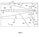
- FIG. 3 is a top view of a tail portion of a fuselage of the example aircraft of FIGS. 1-2 .
- FIG. 4 is a perspective view of the tail portion of the example fuselage of FIGS. 1-3 .
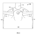
- FIG. 5 is a rear view of the example fuselage of FIGS. 1-4 .
- FIG. 6 is a top view of a tail portion of another example fuselage disclosed herein.
- FIG. 7 is a top view of a tail portion of yet another example fuselage disclosed herein.
- FIG. 8 is a top view of a tail portion of another example fuselage disclosed herein.
- FIG. 9 is a flow chart representative of an example method disclosed herein.
- any part e.g., a layer, film, area, or plate
- positioned on e.g., positioned on, located on, disposed on, or formed on, etc.
- the referenced part is either in contact with the other part, or that the referenced part is above the other part with one or more intermediate part(s) located therebetween.
- Stating that any part is in contact with another part means that there is no intermediate part between the two parts.
- An example apparatus includes a fuselage of an aircraft having a first section and a second section to which a tail assembly is to be coupled.
- the tail assembly includes a horizontal stabilizer and a vertical stabilizer.
- the second section may be aft of the first section and may extend to a trailing edge of the horizontal stabilizer.
- a first width of the first section decreases from a front to a rear of the first section, and a second width of the second section is substantially constant.
- the example apparatus may include a third section aft of the second section.
- the third section may have a third width decreasing from a front to a rear of the third section.
- FIG. 1 is a top view of an example aircraft 100 disclosed herein.
- the aircraft 100 includes a fuselage 102 having a nose portion 104, a central portion 106, and a tail portion 108.
- the nose portion 104 defines a nose-end 110
- the tail portion 108 defines a tail-end 112.
- a first wing 114 and a second wing 116 are coupled to the central portion 106 of the example fuselage 102.
- a first engine 118 and a second engine 120 are coupled to the first wing 114 and the second wing 116, respectively.
- the aircraft 100 illustrated in FIG. 1 is merely an example. Thus, other types of aircraft may be used without departing from the scope of this disclosure.
- the example aircraft 100 of FIG. 1 includes a tail assembly 122 (e.g., an empennage) coupled to the tail portion 108 of the fuselage 102.
- the tail assembly 122 includes a horizontal stabilizer 124 and a vertical stabilizer 126.
- the example horizontal stabilizer 124 includes a first fixed wing 128 and a second fixed wing 130.
- the first fixed wing 128 is disposed on a first side 132 of the fuselage 102
- the second fixed wing 130 is disposed on a second side 134 of the fuselage 102 opposite the first side 132.
- the horizontal stabilizer 124 includes one or more elevators to control a pitch (e.g., up-and-down motion) of the nose-end 110 of the aircraft 100.
- the vertical stabilizer 126 is disposed along a longitudinal axis 136 of the fuselage 102.
- the vertical stabilizer 126 includes a rudder to control a yaw (side-to-side motion) of the nose-end 110 of the aircraft 100.
- FIG. 2 is a side view of the example aircraft 100 of FIG. 1 .
- the tail portion 108 of the fuselage 102 defines an upsweep 200.
- the example vertical stabilizer 126 includes a leading edge 202 and a trailing edge 204.
- the leading edge 202 of the vertical stabilizer 126 extends from the fuselage 102 fore of the horizontal stabilizer 124.
- FIG. 3 is a top view of the tail portion 108 of the example fuselage 102.
- the tail portion 108 includes a first section 300, a second section 302 and a third section 304.
- the tail assembly 122 is disposed on the first section 300 and the second section 302.
- the example third section 304 is disposed aft of the tail assembly 122.
- the first section 300 extends from about the leading edge 202 of the vertical stabilizer 126 to a position along a chord of the horizontal stabilizer 124 (i.e., a position between a leading edge 306 and a trailing edge 308 of the horizontal stabilizer 124). In other examples, the first section 300 extends to and from other positions along the aircraft 100.
- the example second section 302 extends from the first section 300 (i.e., from the position along the chord of the horizontal stabilizer 124) to the trailing edge 308 of the horizontal stabilizer 124. In other examples, the second section 302 extends to and from other positions along the aircraft 100 (e.g., the second section 302 may extend up to a position fore of the trailing edge 308 of the horizontal stabilizer, the second section 302 may extend aft of the trailing edge 308 of the horizontal stabilizer, etc.).
- the example third section 304 of FIG. 3 extends from the second section 302 (i.e., from the trailing edge 308 of the horizontal stabilizer 124) to the rear-end 112 of the fuselage 102. Thus, in the illustrated example, the third section 304 is aft of the horizontal stabilizer 124. In other examples, the third section 304 extends to and from other positions along the aircraft 100.
- the example first section 300 has a first shape.
- a first width of the first section 300 decreases rearwards (i.e., from a front to a rear of the first section 300).
- first lateral surfaces 310 and 312 of the fuselage 102 along the first section 300 are converging inboard.
- the first width of the first section 300 decreases at a constant rate (i.e., the first lateral surfaces 310 and 312 of the fuselage 102 along the first section 300 are substantially straight).
- the first width decreases at an inconstant or varying rate (i.e., the first lateral surfaces 310 and 312 are curved).
- the first lateral surfaces 310 and 312 are converging inboard by more than ten degrees relative to the longitudinal axis 136 of the fuselage 102.
- the first section 300 is other shapes and, thus, the first lateral surfaces 310 and 312 may converge via greater or lesser angles.
- the second section 302 has a second shape in which a second width of the second section 302 is substantially constant (i.e., second lateral surfaces 314 and 316 of the fuselage 102 along the example second section 302 are oriented within about ten degrees of being parallel to the longitudinal axis 136 of the fuselage 102).
- the example second lateral surfaces 314 and 316 of FIG. 3 are parallel to the longitudinal axis 136 of the fuselage 102.
- other examples have other shapes.
- the example third section 304 of FIG. 3 has a third shape.
- a third width of the third section 304 decreases rearwards (i.e., from a front to a rear of the third section 304).
- third lateral surfaces 318 and 320 of the fuselage 102 along the third section 304 converge inboard.
- the third width of the third section 304 decreases at a constant rate (e.g., the third lateral surfaces 318 and 320 of the fuselage 102 along the third section 304 are substantially straight).
- the third width decreases at an inconstant or varying rate (e.g., the third lateral surfaces 318 and 320 are curved).
- the third lateral surfaces 318 and 320 are converging by more than ten degrees relative to the longitudinal axis 136 of the fuselage 102.
- the third section 304 is other shapes and, thus, the third lateral surfaces 318 and 320 may converge via greater or lesser angles.
- the third section 304 defines the tail-end 112.
- FIG. 4 is a perspective view of the tail portion 108 of the example fuselage 102.
- the third section 304 also defines a downsweep 400 (i.e., a top surface 402 of the third section 304 curves downward in the orientation of FIG. 4 ) and a portion of the upsweep 200.
- the example tail-end 112 of the fuselage 102 has a circular cross-section.
- the tail-end 112 is substantially perpendicular to the longitudinal axis 136 of the fuselage 102.
- the above-noted shapes are merely examples and, thus, other shapes (e.g., conical, etc.) may be used without departing from the scope of this disclosure.
- FIG. 5 is a rear view of the tail portion 108 of the example fuselage 102.
- the first side 132 and the second side 134 of the fuselage 102 along the second section 302 define a first planar surface 500 and a second planar surface 502, respectively.
- the first planar surface 500 and the second planar surface 502 are substantially parallel to a longitudinal axis of the vertical stabilizer 126.
- Other examples are other shapes.
- the example fuselage 102 of FIGS. 1-5 produces about one percent less drag than a fuselage 102 having a tail portion 108 with a width that decreases at a constant rate or progression but is otherwise substantially similar to the example fuselage 102 of FIGS. 1-5 .
- FIG. 6 illustrates a tail portion 600 of another example fuselage 602 disclosed herein.
- the tail portion 600 includes a first section 604, a second section 606 and a third section 608.
- a tail assembly 610 is disposed on the first section 604 and the second section 606.
- the tail assembly 610 includes a horizontal stabilizer 612 and a vertical stabilizer 614.
- the example third section 608 is disposed aft of the tail assembly 610.
- the first section 604 extends from fore of the vertical stabilizer 614 to a position along a chord of the horizontal stabilizer 612 (i.e., a position between a leading edge 616 and a trailing edge 618 of the horizontal stabilizer 612).
- the first section 604 extends to and from other positions along the fuselage 602 (e.g., up to the leading edge 616 of the horizontal stabilizer).
- the example second section 606 of FIG. 6 extends from the first section 604 (i.e., from the position along the chord of the horizontal stabilizer 612) to the trailing edge 618 of the horizontal stabilizer 612.
- the second section 606 extends to and from other positions along the fuselage 602.
- the example third section 608 of FIG. 6 extends from the second section 606 (i.e., from the trailing edge 618 of the horizontal stabilizer 612) to a rear-end 620 of the fuselage 602.
- the third section 608 is aft of the horizontal stabilizer 612.
- the third section 608 extends to and from other positions along the fuselage 602.
- the example first section 604 has a first shape.
- a first width of the first section 604 decreases rearwards (i.e., from a front to a rear of the first section 604).
- first lateral surfaces 622 and 624 of the fuselage 602 along the first section 604 are converging inboard.
- the first width of the first section 604 decreases at a constant rate (i.e., the first lateral surfaces 622 and 624 of the fuselage 602 along the first section 604 are substantially straight).
- the first width decreases at an inconstant or varying rate (i.e., the first lateral surfaces 622 and 624 are curved).
- the first lateral surfaces 622 and 624 are converging inboard by more than ten degrees relative to a longitudinal axis 625 of the fuselage 602.
- the first section 604 is other shapes and, thus, the first lateral surfaces 622 and 624 may converge via greater or lesser angles.
- the second section 606 has a second shape in which a second width of the second section 606 is substantially constant (i.e., second lateral surfaces 626 and 628 of the fuselage 602 along the example second section 606 are oriented within about ten degrees of being parallel to the longitudinal axis 625 of the fuselage 602).
- the second lateral surfaces 626 and 628 are converging inboard such that the second lateral surfaces 626 and 628 are oriented about five degrees from parallel to the longitudinal axis 625 of the fuselage 602.
- the above noted-shape is merely an example and, thus, other shapes may be used without departing from the scope of this disclosure.
- the example third section 608 has a third shape.
- a third width of the third section 608 decreases rearwards (i.e., from a front to a rear of the third section 608).
- third lateral surfaces 630 and 632 of the fuselage 602 along the third section 608 converge inboard.
- the third width of the third section 608 decreases at a constant rate (e.g., the third lateral surfaces 630 and 632 of the fuselage 602 along the third section 608 are substantially straight).
- the third width decreases at an inconstant or varying rate (e.g., the third lateral surfaces 630 and 632 are curved).
- the third lateral surfaces 630 and 632 are converging by more than ten degrees relative to the longitudinal axis 625 of the fuselage 602.
- the third section 608 is other shapes and, thus, the third lateral surfaces 630 and 632 may converge via greater or lesser angles.
- the third section 608 defines the tail-end 620 of the fuselage 602.
- FIG. 7 illustrates a tail portion 700 of another example fuselage 702 disclosed herein.
- the tail portion 700 includes a first section 704, a second section 706 and a third section 708.
- a tail assembly 710 is disposed on the first section 704 and the second section 706.
- the tail assembly 710 includes a horizontal stabilizer 712 and a vertical stabilizer 714.
- the example third section 708 is disposed aft of the tail assembly 710.
- the first section 704 extends from fore of the vertical stabilizer 714 to a position along a chord of the horizontal stabilizer 712 (i.e., a position between a leading edge 716 and a trailing edge 718 of the horizontal stabilizer 712).
- the first section 704 extends to and from other positions along the fuselage 702 (e.g., up to the leading edge 716 of the horizontal stabilizer 712).
- the example second section 706 extends from the first section 704 (i.e., from the position along the chord of the horizontal stabilizer 712) to the trailing edge 718 of the horizontal stabilizer 712.
- the second section 706 extends to and from other positions along the fuselage 702.
- the example third section 708 of FIG. 7 extends from the second section 706 (i.e., from the trailing edge 718 of the horizontal stabilizer 712) to a rear-end 720 of the fuselage 702.
- the third section 708 is aft of the horizontal stabilizer 712.
- the third section 708 extends to and from other positions along the fuselage 702.
- the example first section 704 has a first shape.
- a first width of the first section 704 decreases rearwards (i.e., from a front to a rear of the first section 704).
- first lateral surfaces 722 and 724 of the fuselage 702 along the first section 704 are converging inboard.
- the first width of the first section 704 decreases at a constant rate (i.e., the first lateral surfaces 722 and 724 of the fuselage 702 along the third section 708 are substantially straight).
- the first width decreases at an inconstant or varying rate (i.e., the first lateral surfaces 722 and 724 are curved).
- the first lateral surfaces 722 and 724 are converging inboard by more than ten degrees relative to a longitudinal axis 725 of the fuselage 702.
- the first section 704 is other shapes and, thus, the first lateral surfaces 722 and 724 may converge via greater or lesser angles.
- the second section 706 has a second shape in which a second width of the second section 706 is substantially constant (i.e., second lateral surfaces 726 and 728 of the fuselage 702 along the example second section 706 are oriented within about ten degrees of being parallel to the longitudinal axis 725 of the fuselage 702).
- the second lateral surfaces 726 and 728 are diverging outboard such that the second lateral surfaces 726 and 728 are oriented about five degrees from parallel to the longitudinal axis 725 of the fuselage 702.
- the orientation of the second lateral surfaces 726 and 728 of FIG. 7 is merely an example.
- the second lateral surfaces 726 and 728 have other orientations.
- a projection 729 extends from the second lateral surface 726.
- the projection 729 is coupled to the second lateral surface 726.
- the projection 729 and the second lateral surface 726 are integrally formed.
- the projection 729 curves outward relative to the second lateral surface 726.
- the projection 729 may be a cover or housing surrounding some or all of one or more components disposed inside the tail portion 700.
- the projection 729 defines an outlet such as, for example, an exhaust outlet.
- the above noted-shapes are merely examples and, thus, other shapes may be used without departing from the scope of this disclosure.
- the projection 729 is disposed in a different position along the tail portion 700 than illustrated in FIG.
- the tail portion 700 includes one or more recesses.
- the example third section 708 has a third shape.
- a third width of the third section 708 decreases rearwards (i.e., from a front to a rear of the third section 708).
- third lateral surfaces 730 and 732 of the fuselage 702 along the third section 708 converge inboard.
- the third width of the third section 708 decreases at a constant rate (e.g., the third lateral surfaces 730 and 732 of the fuselage 702 along the third section 708 are substantially straight).
- the third width decreases at an inconstant or varying rate (e.g., the third lateral surfaces 730 and 732 are curved).
- the third lateral surfaces 730 and 732 are converging by more than ten degrees relative to the longitudinal axis 725 of the fuselage 702.
- the third section 708 is other shapes and, thus, the third lateral surfaces 730 and 732 may converge via greater or lesser angles.
- the third section 708 defines the tail-end 720 of the fuselage 702.
- FIG. 8 illustrates a tail portion 800 of another example fuselage 802 disclosed herein.
- the tail portion 800 includes a first section 804, a second section 806 and a third section 808.
- a tail assembly 810 is disposed on the first section 804 and the second section 806.
- the tail assembly 810 includes a horizontal stabilizer 812 and a vertical stabilizer 814.
- the example third section 808 is disposed aft of the tail assembly 810.
- the first section 804 extends from fore of the vertical stabilizer 814 to a leading edge 816 of the horizontal stabilizer 812. In other examples, the first section 804 extends to and from other positions along the fuselage 802.
- the example second section 806 extends from the first section 804 (i.e., from the leading edge 816 of the horizontal stabilizer 812) to a trailing edge 818 of the horizontal stabilizer 812.
- the example second section 804 of FIG. 8 extends a distance corresponding to a length of a chord of the horizontal stabilizer 812.
- the third section 808 is aft of the horizontal stabilizer 812.
- the example first section 804 has a first shape.
- a first width of the first section 804 decreases rearwards (i.e., from a front to a rear of the first section 804).
- first lateral surfaces 822 and 824 of the fuselage along the first section 804 are converging inboard.
- the first width of the first section 804 decreases at a constant rate (i.e., the first lateral surfaces 822 and 824 of the fuselage along the third section 808 are substantially straight).
- the first width decreases at an inconstant or varying rate (i.e., the first lateral surfaces 822 and 824 are curved).
- the first lateral surfaces 822 and 824 are converging inboard by more than ten degrees relative to a longitudinal axis 825 of the fuselage 802.
- the first section 804 is other shapes and, thus, the first lateral surfaces 822 and 824 may converge via greater or lesser angles.
- the second section 806 has a second shape in which a second width of the second section 806 is substantially constant (i.e., second lateral surfaces 826 and 828 of the fuselage along the example second section 806 are oriented within about ten degrees of being parallel to the longitudinal axis 825 of the fuselage 802).
- the second lateral surfaces 826 and 828 are parallel to the longitudinal axis 825 of the fuselage 802.
- the above noted-shape is merely an example and, thus, other shapes may be used without departing from the scope of this disclosure.
- the example third section 808 has a third shape.
- a third width of the third section 808 decreases rearwards (i.e., from a front to a rear of the third section 808).
- third lateral surfaces 830 and 832 of the fuselage 802 along the third section 808 converges inboard.
- the third width of the third section 808 decreases at a constant rate (e.g., the third lateral surfaces 830 and 832 of the fuselage 802 along the third section 808 are substantially straight).
- the third width decreases at an inconstant or varying rate (e.g., the third lateral surfaces 830 and 832 are curved).
- the third lateral surfaces 830 and 832 are converging by more than ten degrees relative to the longitudinal axis 825 of the fuselage 802.
- the third section 808 is other shapes and, thus, the third lateral surfaces 830 and 832 may converge via greater or lesser angles.
- the third section 808 defines the tail-end 820 of the fuselage 802.
- FIG. 9 depicts an example flow diagram representative of methods or processes that may be implemented using, for example, computer readable instructions.
- the example process of FIG. 9 may be performed using a processor, a controller and/or any other suitable processing device.
- the example process of FIG. 9 may be implemented using coded instructions (e.g., computer readable instructions) stored on a tangible computer readable medium such as a flash memory, a read-only memory (ROM), and/or a random-access memory (RAM).
- coded instructions e.g., computer readable instructions
- ROM read-only memory
- RAM random-access memory
- the term tangible computer readable medium is expressly defined to include any type of computer readable storage and to exclude propagating signals. Additionally or alternatively, the example process of FIG.
- non-transitory computer readable medium such as a flash memory, a read-only memory (ROM), a random-access memory (RAM), a cache, or any other storage media in which information is stored for any duration (e.g., for extended time periods, permanently, brief instances, for temporarily buffering, and/or for caching of the information).
- a non-transitory computer readable medium such as a flash memory, a read-only memory (ROM), a random-access memory (RAM), a cache, or any other storage media in which information is stored for any duration (e.g., for extended time periods, permanently, brief instances, for temporarily buffering, and/or for caching of the information).
- a non-transitory computer readable medium such as a flash memory, a read-only memory (ROM), a random-access memory (RAM), a cache, or any other storage media in which information is stored for any duration (e.g., for extended time periods, permanently, brief instances, for temporarily buffering, and/or for caching of the information).
- FIG. 9 may be implemented using any combination(s) of application specific integrated circuit(s) (ASIC(s)), programmable logic device(s) (PLD(s)), field programmable logic device(s) (FPLD(s)), discrete logic, hardware, firmware, etc. Also, one or more operations depicted in FIG. 9 may be implemented manually or as any combination(s) of any of the foregoing techniques, for example, any combination of firmware, software, discrete logic and/or hardware.
- ASIC application specific integrated circuit
- PLD programmable logic device
- FPLD field programmable logic device
- FIG. 9 is described with reference to the flow diagram of FIG. 9 , other methods of implementing the process of FIG. 9 may be employed.
- the order of execution of the blocks may be changed, and/or some of the blocks described may be changed, eliminated, sub-divided, or combined.
- one or more of the operations depicted in FIG. 9 may be performed sequentially and/or in parallel by, for example, separate processing threads, processors, devices, discrete logic, circuits, etc.
- FIG. 9 is a flowchart representative of an example method 900 that can be performed to improve aerodynamic performance of an aircraft.
- the example method 900 of FIG. 9 begins by directing the first lateral surfaces 310 and 312 of the first section 300 of the fuselage 108 to be converging inboard from a front to a rear of the first section 300 (block 902).
- the first lateral surfaces 310 and 312 are directed from fore of a first position along the fuselage 108 corresponding to a leading edge 202 of the vertical stabilizer 126 to or past a second position along the fuselage 108 corresponding to the leading edge 616 of the horizontal stabilizer 124.
- the second lateral surfaces 314 and 316 of the second section 302 are directed to be substantially parallel.
- the second section 302 and, thus, the second lateral surfaces 314 and 316 are aft of the first section 300.
- the second lateral surfaces 314 and 316 are directed to be substantially parallel such that the second lateral surfaces 314 and 316 are oriented ten degrees or less from being parallel to the longitudinal axis 136 of the fuselage 108.
- the second lateral surfaces 314 and 316 are directed from the first section 300 (e.g., from the first lateral surfaces 310 and 312, from the second position along the fuselage 108 corresponding to the leading edge 306 of the horizontal stabilizer 124, from a third position aft of the second position, etc.).
- the second lateral surfaces 314 and 316 are directed to a fourth position corresponding to the trailing edge 308 of the horizontal stabilizer 124.
- the third lateral surfaces 318 and 320 of the third section 304 of the fuselage 108 are directed to be converging from a front to the rear of the third section 304.
- the third section 304 is aft of the second section 302.
- the third lateral surfaces 318 and 320 are directed from the second section 302 (e.g., from the second lateral surfaces 314 and 316, from the fourth position along the fuselage 108 corresponding to the trailing edge 308 of the horizontal stabilizer, etc.) to the tail-end 112 of the aircraft 100.
- the tail assembly 122 is coupled to the first section 300 and the second section 302.
- the leading edge 306 of the horizontal stabilizer 124 is extended from the first section 300.
- the leading edge 306 of the horizontal stabilizer 124 is extended from the second section 302.
- the vertical stabilizer 126 may be extended from the first section 300 and/or the second section 302.
Landscapes
- Engineering & Computer Science (AREA)
- Aviation & Aerospace Engineering (AREA)
- Manufacturing & Machinery (AREA)
- Mechanical Engineering (AREA)
- Physics & Mathematics (AREA)
- Fluid Mechanics (AREA)
- Transportation (AREA)
- Aerodynamic Tests, Hydrodynamic Tests, Wind Tunnels, And Water Tanks (AREA)
- Vehicle Body Suspensions (AREA)
- Body Structure For Vehicles (AREA)
Abstract
Description
- The present disclosure relates generally to aircraft and, more particularly, to aircraft fuselages.
- An aircraft generally includes a tail assembly coupled to a fuselage. The tail assembly may include a horizontal stabilizer and a vertical stabilizer positioned adjacent a rear end of the fuselage. Typically, the horizontal stabilizer limits pitching motion of a nose of the aircraft, and the vertical stabilizer limits yawing motion of the nose. During flight, air flowing across the fuselage and the tail assembly produces drag on the aircraft.
- An example apparatus includes a fuselage of an aircraft having a first section and a second section to which a tail assembly is to be coupled. The second section is aft of the first section and is to extend to at least a trailing edge of a horizontal stabilizer of the tail assembly. A first width of the first section decreases from a front to a rear of the first section, and a second width of the second section is substantially constant.
- Another example apparatus includes a portion of a fuselage to which a tail assembly is to be coupled. The portion of the fuselage includes a first section, a second section and a third section. First lateral surfaces of the first section are converging inboard. The second section is aft of the first section and has substantially parallel second lateral surfaces. The second section is to extend to a trailing edge of a horizontal stabilizer of the tail assembly. The third section is aft of the second section and has third lateral surfaces converging inboard
- Another example apparatus includes a first section of a fuselage of an aircraft having a first shape such that lateral surfaces of the first section are converging from a front to a rear of the first section by more than ten degrees relative to a longitudinal axis of the fuselage. A vertical stabilizer is to be disposed along a portion of the first section. The example apparatus also includes a second section of the fuselage aft of the first section. The second section has a second shape such that lateral surfaces of the second section are oriented ten degrees or less from being parallel to the longitudinal axis of the fuselage. The second section is to extend to a trailing edge of a horizontal stabilizer.
- An example method disclosed herein includes directing first lateral surfaces of a first section of a fuselage of an aircraft to be converging inboard from a front to a rear of the first section. The example method further includes directing second lateral surfaces of a second section of the fuselage to be substantially parallel. The second lateral surfaces are to be aft of the first section and are to extend to at least a trailing edge of a horizontal stabilizer.
- The invention involves an apparatus that may include a fuselage of an aircraft having a first section and a second section to which a tail assembly is to be coupled, the second section aft of the first section and to extend to at least a trailing edge of a horizontal stabilizer of the tail assembly, a first width of the first section decreasing from a front to a rear of the first section, a second width of the second section being substantially constant. The fuselage may include a third section aft of the second section, a third width of the third section decreasing from a front to a rear of the third section. A portion of the horizontal stabilizer may be disposed along the first section. The second section may extend from a leading edge of the horizontal stabilizer. The second width may be substantially constant such that lateral surfaces of the second section are oriented within about ten degrees of being parallel to a longitudinal axis of the fuselage. The sides of the second section may be substantially parallel to a longitudinal axis of a vertical stabilizer of the tail assembly.
- The invention may involve an apparatus that can include a portion of a fuselage to which a tail assembly is to be coupled, the portion of the fuselage including a first section, a second section and a third section, first lateral surfaces of the first section converging inboard, the second section aft of the first section and having substantially parallel second lateral surfaces, the second section to extend to at least a trailing edge of a horizontal stabilizer of the tail assembly, the third section aft of the second section and having third lateral surfaces converging inboard. At least a portion of the first section may be disposed fore of a leading edge of the horizontal stabilizer. A portion the first section may be disposed aft of a leading edge of the horizontal stabilizer. The second section can be to extend from a leading edge of the horizontal stabilizer to the trailing edge of the horizontal stabilizer. The second section may be to extend from aft of a leading edge of the horizontal stabilizer to the trailing edge of the horizontal stabilizer. The third section may be disposed aft of the trailing edge of the horizontal stabilizer. The second lateral surfaces of the second section may converge or diverge by ten degrees or less relative to a longitudinal axis of the fuselage.
- The invention may involve an apparatus that can include a first section of a fuselage of an aircraft having a first shape such that lateral surfaces of the first section are converging from a front to a rear of the first section by more than ten degrees relative to a longitudinal axis of the fuselage, a vertical stabilizer is to be disposed along a portion of the first section; and a second section of the fuselage aft of the first section, the second section having a second shape such that lateral surfaces of the second section are oriented ten degrees or less from being parallel to the longitudinal axis of the fuselage, the second section to extend to at least a trailing edge of a horizontal stabilizer. The apparatus may include a third section aft of the second section, the third section having a third shape such that lateral surfaces of the third section are converging from a front to a rear of the third section by more than ten degrees relative to the longitudinal axis of the fuselage. The first section may extend from fore of a leading edge of the horizontal stabilizer to aft of the leading edge of the horizontal stabilizer. The second section may be to extend from a leading edge of the horizontal stabilizer to the trailing edge of the horizontal stabilizer. The lateral surfaces of the second section may be parallel to the longitudinal axis of the fuselage. The lateral surfaces of the second section may be converging. The lateral surfaces of the second section may be diverging.
- The invention can involve a method that may include directing first lateral surfaces of a first section of a fuselage of an aircraft to be converging inboard from a front to a rear of the first section; and directing second lateral surfaces of a second section of the fuselage to be substantially parallel, the second lateral surfaces to be aft of the first section and to extend to at least a trailing edge of a horizontal stabilizer. The method may also include directing third lateral surfaces of a third section of the fuselage to be converging inboard from a front to a rear of the third section, the third section to be aft of the second section. The method may also include coupling the tail assembly to the first section and the second section. The method may also include directing the second lateral surfaces from the first lateral surfaces. Directing the second lateral surfaces to be substantially parallel may include directing the second lateral surfaces to be oriented ten degrees or less from being parallel to a longitudinal axis of the fuselage. The method may also include directing the second lateral surfaces from aft of a position corresponding to a leading edge of the horizontal stabilizer. The method may also include directing the second lateral surfaces from a position corresponding to a leading edge of the horizontal stabilizer.
- The features, functions and advantages that have been discussed can be achieved independently in various examples or may be combined in yet other examples further details of which can be seen with reference to the following description and drawings.
-
FIG. 1 is a top view of an example aircraft disclosed herein. -
FIG. 2 is a side view of the example aircraft ofFIG. 1 . -
FIG. 3 is a top view of a tail portion of a fuselage of the example aircraft ofFIGS. 1-2 . -
FIG. 4 is a perspective view of the tail portion of the example fuselage ofFIGS. 1-3 . -
FIG. 5 is a rear view of the example fuselage ofFIGS. 1-4 . -
FIG. 6 is a top view of a tail portion of another example fuselage disclosed herein. -
FIG. 7 is a top view of a tail portion of yet another example fuselage disclosed herein. -
FIG. 8 is a top view of a tail portion of another example fuselage disclosed herein. -
FIG. 9 is a flow chart representative of an example method disclosed herein. - Wherever possible, the same reference numbers will be used throughout the drawing(s) and accompanying written description to refer to the same or like parts. As used in this disclosure, stating that any part (e.g., a layer, film, area, or plate) is in any way positioned on (e.g., positioned on, located on, disposed on, or formed on, etc.) another part, means that the referenced part is either in contact with the other part, or that the referenced part is above the other part with one or more intermediate part(s) located therebetween. Stating that any part is in contact with another part means that there is no intermediate part between the two parts.
- Aircraft fuselages are disclosed herein. An example apparatus includes a fuselage of an aircraft having a first section and a second section to which a tail assembly is to be coupled. In some examples, the tail assembly includes a horizontal stabilizer and a vertical stabilizer. The second section may be aft of the first section and may extend to a trailing edge of the horizontal stabilizer. In some examples, a first width of the first section decreases from a front to a rear of the first section, and a second width of the second section is substantially constant. The example apparatus may include a third section aft of the second section. In some such examples, the third section may have a third width decreasing from a front to a rear of the third section. During flight, air flowing over the tail portion produces drag on the aircraft. However, the shape of the example tail portion substantially prevents air flow separation along the tail portion of the fuselage.
-
FIG. 1 is a top view of anexample aircraft 100 disclosed herein. In the illustrated example, theaircraft 100 includes afuselage 102 having anose portion 104, acentral portion 106, and atail portion 108. In the illustrated example, thenose portion 104 defines a nose-end 110, and thetail portion 108 defines a tail-end 112. Afirst wing 114 and asecond wing 116 are coupled to thecentral portion 106 of theexample fuselage 102. In the illustrated example, afirst engine 118 and asecond engine 120 are coupled to thefirst wing 114 and thesecond wing 116, respectively. Theaircraft 100 illustrated inFIG. 1 is merely an example. Thus, other types of aircraft may be used without departing from the scope of this disclosure. - The
example aircraft 100 ofFIG. 1 includes a tail assembly 122 (e.g., an empennage) coupled to thetail portion 108 of thefuselage 102. In the illustrated example, thetail assembly 122 includes ahorizontal stabilizer 124 and avertical stabilizer 126. The examplehorizontal stabilizer 124 includes a firstfixed wing 128 and a secondfixed wing 130. In the illustrated example, the firstfixed wing 128 is disposed on afirst side 132 of thefuselage 102, and the secondfixed wing 130 is disposed on asecond side 134 of thefuselage 102 opposite thefirst side 132. In some examples, thehorizontal stabilizer 124 includes one or more elevators to control a pitch (e.g., up-and-down motion) of the nose-end 110 of theaircraft 100. In the illustrated example, thevertical stabilizer 126 is disposed along alongitudinal axis 136 of thefuselage 102. In some examples, thevertical stabilizer 126 includes a rudder to control a yaw (side-to-side motion) of the nose-end 110 of theaircraft 100. -
FIG. 2 is a side view of theexample aircraft 100 ofFIG. 1 . In the illustrated example, thetail portion 108 of thefuselage 102 defines anupsweep 200. The examplevertical stabilizer 126 includes aleading edge 202 and a trailingedge 204. In the illustrated example, theleading edge 202 of thevertical stabilizer 126 extends from thefuselage 102 fore of thehorizontal stabilizer 124. -
FIG. 3 is a top view of thetail portion 108 of theexample fuselage 102. In the illustrated example, thetail portion 108 includes afirst section 300, asecond section 302 and athird section 304. In the illustrated example, thetail assembly 122 is disposed on thefirst section 300 and thesecond section 302. The examplethird section 304 is disposed aft of thetail assembly 122. In the illustrated example, thefirst section 300 extends from about theleading edge 202 of thevertical stabilizer 126 to a position along a chord of the horizontal stabilizer 124 (i.e., a position between aleading edge 306 and a trailingedge 308 of the horizontal stabilizer 124). In other examples, thefirst section 300 extends to and from other positions along theaircraft 100. The examplesecond section 302 extends from the first section 300 (i.e., from the position along the chord of the horizontal stabilizer 124) to the trailingedge 308 of thehorizontal stabilizer 124. In other examples, thesecond section 302 extends to and from other positions along the aircraft 100 (e.g., thesecond section 302 may extend up to a position fore of the trailingedge 308 of the horizontal stabilizer, thesecond section 302 may extend aft of the trailingedge 308 of the horizontal stabilizer, etc.). The examplethird section 304 ofFIG. 3 extends from the second section 302 (i.e., from the trailingedge 308 of the horizontal stabilizer 124) to the rear-end 112 of thefuselage 102. Thus, in the illustrated example, thethird section 304 is aft of thehorizontal stabilizer 124. In other examples, thethird section 304 extends to and from other positions along theaircraft 100. - The example
first section 300 has a first shape. In the illustrated example, a first width of thefirst section 300 decreases rearwards (i.e., from a front to a rear of the first section 300). Thus, firstlateral surfaces fuselage 102 along thefirst section 300 are converging inboard. In some examples, the first width of thefirst section 300 decreases at a constant rate (i.e., the first lateral surfaces 310 and 312 of thefuselage 102 along thefirst section 300 are substantially straight). In other examples, the first width decreases at an inconstant or varying rate (i.e., the first lateral surfaces 310 and 312 are curved). In the illustrated example, the first lateral surfaces 310 and 312 are converging inboard by more than ten degrees relative to thelongitudinal axis 136 of thefuselage 102. In other examples, thefirst section 300 is other shapes and, thus, the first lateral surfaces 310 and 312 may converge via greater or lesser angles. - In the illustrated example, the
second section 302 has a second shape in which a second width of thesecond section 302 is substantially constant (i.e., second lateral surfaces 314 and 316 of thefuselage 102 along the examplesecond section 302 are oriented within about ten degrees of being parallel to thelongitudinal axis 136 of the fuselage 102). The example second lateral surfaces 314 and 316 ofFIG. 3 are parallel to thelongitudinal axis 136 of thefuselage 102. As described in greater detail below, other examples have other shapes. - The example
third section 304 ofFIG. 3 has a third shape. In the illustrated example, a third width of thethird section 304 decreases rearwards (i.e., from a front to a rear of the third section 304). Thus, thirdlateral surfaces fuselage 102 along thethird section 304 converge inboard. In some examples, the third width of thethird section 304 decreases at a constant rate (e.g., the thirdlateral surfaces fuselage 102 along thethird section 304 are substantially straight). In other examples, the third width decreases at an inconstant or varying rate (e.g., the thirdlateral surfaces lateral surfaces longitudinal axis 136 of thefuselage 102. In other examples, thethird section 304 is other shapes and, thus, the thirdlateral surfaces third section 304 defines the tail-end 112. -
FIG. 4 is a perspective view of thetail portion 108 of theexample fuselage 102. In the illustrated example, as the third width of thethird section 304 decreases, thethird section 304 also defines a downsweep 400 (i.e., atop surface 402 of thethird section 304 curves downward in the orientation ofFIG. 4 ) and a portion of theupsweep 200. As a result, the example tail-end 112 of thefuselage 102 has a circular cross-section. In the illustrated example, the tail-end 112 is substantially perpendicular to thelongitudinal axis 136 of thefuselage 102. However, the above-noted shapes are merely examples and, thus, other shapes (e.g., conical, etc.) may be used without departing from the scope of this disclosure. -
FIG. 5 is a rear view of thetail portion 108 of theexample fuselage 102. In the illustrated example, thefirst side 132 and thesecond side 134 of thefuselage 102 along thesecond section 302 define a firstplanar surface 500 and a secondplanar surface 502, respectively. In the illustrated example, the firstplanar surface 500 and the secondplanar surface 502 are substantially parallel to a longitudinal axis of thevertical stabilizer 126. Other examples are other shapes. - During flight, air passing over the
fuselage 102 and thetail assembly 122 produces drag on theexample aircraft 100. However, the example shapes of thefirst section 300, thesecond section 302 and/or thethird section 304 of thetail portion 108 substantially prevent air flow separation along thetail portion 108 of thefuselage 102. As a result, theexample fuselage 102 ofFIGS. 1-5 produces about one percent less drag than afuselage 102 having atail portion 108 with a width that decreases at a constant rate or progression but is otherwise substantially similar to theexample fuselage 102 ofFIGS. 1-5 . -
FIG. 6 illustrates atail portion 600 of anotherexample fuselage 602 disclosed herein. In the illustrated example, thetail portion 600 includes afirst section 604, asecond section 606 and athird section 608. In the illustrated example, atail assembly 610 is disposed on thefirst section 604 and thesecond section 606. In the illustrated example, thetail assembly 610 includes ahorizontal stabilizer 612 and avertical stabilizer 614. The examplethird section 608 is disposed aft of thetail assembly 610. In the illustrated example, thefirst section 604 extends from fore of thevertical stabilizer 614 to a position along a chord of the horizontal stabilizer 612 (i.e., a position between aleading edge 616 and a trailingedge 618 of the horizontal stabilizer 612). In other examples, thefirst section 604 extends to and from other positions along the fuselage 602 (e.g., up to theleading edge 616 of the horizontal stabilizer). The examplesecond section 606 ofFIG. 6 extends from the first section 604 (i.e., from the position along the chord of the horizontal stabilizer 612) to the trailingedge 618 of thehorizontal stabilizer 612. In other examples, thesecond section 606 extends to and from other positions along thefuselage 602. The examplethird section 608 ofFIG. 6 extends from the second section 606 (i.e., from the trailingedge 618 of the horizontal stabilizer 612) to a rear-end 620 of thefuselage 602. Thus, in the illustrated example, thethird section 608 is aft of thehorizontal stabilizer 612. In other examples, thethird section 608 extends to and from other positions along thefuselage 602. - The example
first section 604 has a first shape. In the illustrated example, a first width of thefirst section 604 decreases rearwards (i.e., from a front to a rear of the first section 604). Thus, firstlateral surfaces fuselage 602 along thefirst section 604 are converging inboard. In some examples, the first width of thefirst section 604 decreases at a constant rate (i.e., the first lateral surfaces 622 and 624 of thefuselage 602 along thefirst section 604 are substantially straight). In other examples, the first width decreases at an inconstant or varying rate (i.e., the first lateral surfaces 622 and 624 are curved). In the illustrated example, the first lateral surfaces 622 and 624 are converging inboard by more than ten degrees relative to a longitudinal axis 625 of thefuselage 602. In other examples, thefirst section 604 is other shapes and, thus, the first lateral surfaces 622 and 624 may converge via greater or lesser angles. - In the illustrated example, the
second section 606 has a second shape in which a second width of thesecond section 606 is substantially constant (i.e., second lateral surfaces 626 and 628 of thefuselage 602 along the examplesecond section 606 are oriented within about ten degrees of being parallel to the longitudinal axis 625 of the fuselage 602). In the illustrated example, the second lateral surfaces 626 and 628 are converging inboard such that the second lateral surfaces 626 and 628 are oriented about five degrees from parallel to the longitudinal axis 625 of thefuselage 602. However, the above noted-shape is merely an example and, thus, other shapes may be used without departing from the scope of this disclosure. - The example
third section 608 has a third shape. In the illustrated example, a third width of thethird section 608 decreases rearwards (i.e., from a front to a rear of the third section 608). Thus, thirdlateral surfaces fuselage 602 along thethird section 608 converge inboard. In some examples, the third width of thethird section 608 decreases at a constant rate (e.g., the thirdlateral surfaces fuselage 602 along thethird section 608 are substantially straight). In other examples, the third width decreases at an inconstant or varying rate (e.g., the thirdlateral surfaces lateral surfaces fuselage 602. In other examples, thethird section 608 is other shapes and, thus, the thirdlateral surfaces third section 608 defines the tail-end 620 of thefuselage 602. -
FIG. 7 illustrates atail portion 700 of anotherexample fuselage 702 disclosed herein. In the illustrated example, thetail portion 700 includes afirst section 704, asecond section 706 and athird section 708. In the illustrated example, atail assembly 710 is disposed on thefirst section 704 and thesecond section 706. In the illustrated example, thetail assembly 710 includes ahorizontal stabilizer 712 and avertical stabilizer 714. The examplethird section 708 is disposed aft of thetail assembly 710. In the illustrated example, thefirst section 704 extends from fore of thevertical stabilizer 714 to a position along a chord of the horizontal stabilizer 712 (i.e., a position between aleading edge 716 and a trailingedge 718 of the horizontal stabilizer 712). In other examples, thefirst section 704 extends to and from other positions along the fuselage 702 (e.g., up to theleading edge 716 of the horizontal stabilizer 712). The examplesecond section 706 extends from the first section 704 (i.e., from the position along the chord of the horizontal stabilizer 712) to the trailingedge 718 of thehorizontal stabilizer 712. In other examples, thesecond section 706 extends to and from other positions along thefuselage 702. The examplethird section 708 ofFIG. 7 extends from the second section 706 (i.e., from the trailingedge 718 of the horizontal stabilizer 712) to a rear-end 720 of thefuselage 702. Thus, in the illustrated example, thethird section 708 is aft of thehorizontal stabilizer 712. In other examples, thethird section 708 extends to and from other positions along thefuselage 702. - The example
first section 704 has a first shape. In the illustrated example, a first width of thefirst section 704 decreases rearwards (i.e., from a front to a rear of the first section 704). Thus, firstlateral surfaces fuselage 702 along thefirst section 704 are converging inboard. In some examples, the first width of thefirst section 704 decreases at a constant rate (i.e., the first lateral surfaces 722 and 724 of thefuselage 702 along thethird section 708 are substantially straight). In other examples, the first width decreases at an inconstant or varying rate (i.e., the first lateral surfaces 722 and 724 are curved). In the illustrated example, the first lateral surfaces 722 and 724 are converging inboard by more than ten degrees relative to a longitudinal axis 725 of thefuselage 702. In other examples, thefirst section 704 is other shapes and, thus, the first lateral surfaces 722 and 724 may converge via greater or lesser angles. - In the illustrated example, the
second section 706 has a second shape in which a second width of thesecond section 706 is substantially constant (i.e., second lateral surfaces 726 and 728 of thefuselage 702 along the examplesecond section 706 are oriented within about ten degrees of being parallel to the longitudinal axis 725 of the fuselage 702). In the illustrated example, the second lateral surfaces 726 and 728 are diverging outboard such that the second lateral surfaces 726 and 728 are oriented about five degrees from parallel to the longitudinal axis 725 of thefuselage 702. However, the orientation of the second lateral surfaces 726 and 728 ofFIG. 7 is merely an example. Thus, in other examples, the second lateral surfaces 726 and 728 have other orientations. - In the illustrated example, a
projection 729 extends from the secondlateral surface 726. In some examples, theprojection 729 is coupled to the secondlateral surface 726. In other examples, theprojection 729 and the secondlateral surface 726 are integrally formed. In the illustrated example, theprojection 729 curves outward relative to the secondlateral surface 726. Theprojection 729 may be a cover or housing surrounding some or all of one or more components disposed inside thetail portion 700. In some examples, theprojection 729 defines an outlet such as, for example, an exhaust outlet. Further, the above noted-shapes are merely examples and, thus, other shapes may be used without departing from the scope of this disclosure. In some examples, theprojection 729 is disposed in a different position along thetail portion 700 than illustrated inFIG. 7 (e.g., along thefirst section 704, thethird section 708, the other secondlateral surface 728, an upsweep, etc.). Although the illustrated example includes theprojection 729, other examples include other projections and/or no projections. In some examples, thetail portion 700 includes one or more recesses. - The example
third section 708 has a third shape. In the illustrated example, a third width of thethird section 708 decreases rearwards (i.e., from a front to a rear of the third section 708). Thus, thirdlateral surfaces fuselage 702 along thethird section 708 converge inboard. In some examples, the third width of thethird section 708 decreases at a constant rate (e.g., the thirdlateral surfaces fuselage 702 along thethird section 708 are substantially straight). In other examples, the third width decreases at an inconstant or varying rate (e.g., the thirdlateral surfaces lateral surfaces fuselage 702. In other examples, thethird section 708 is other shapes and, thus, the thirdlateral surfaces third section 708 defines the tail-end 720 of thefuselage 702. -
FIG. 8 illustrates atail portion 800 of anotherexample fuselage 802 disclosed herein. In the illustrated example, thetail portion 800 includes afirst section 804, asecond section 806 and athird section 808. In the illustrated example, atail assembly 810 is disposed on thefirst section 804 and thesecond section 806. In the illustrated example, thetail assembly 810 includes ahorizontal stabilizer 812 and avertical stabilizer 814. The examplethird section 808 is disposed aft of thetail assembly 810. - In the illustrated example, the
first section 804 extends from fore of thevertical stabilizer 814 to aleading edge 816 of thehorizontal stabilizer 812. In other examples, thefirst section 804 extends to and from other positions along thefuselage 802. The examplesecond section 806 extends from the first section 804 (i.e., from theleading edge 816 of the horizontal stabilizer 812) to a trailingedge 818 of thehorizontal stabilizer 812. Thus, the examplesecond section 804 ofFIG. 8 extends a distance corresponding to a length of a chord of thehorizontal stabilizer 812. The examplethird section 808 ofFIG. 8 extends from the second section 806 (i.e., from the trailingedge 818 of the horizontal stabilizer 812) to a rear-end 820 of thefuselage 802. Thus, in the illustrated example, thethird section 808 is aft of thehorizontal stabilizer 812. - The example
first section 804 has a first shape. In the illustrated example, a first width of thefirst section 804 decreases rearwards (i.e., from a front to a rear of the first section 804). Thus, firstlateral surfaces first section 804 are converging inboard. In some examples, the first width of thefirst section 804 decreases at a constant rate (i.e., the first lateral surfaces 822 and 824 of the fuselage along thethird section 808 are substantially straight). In other examples, the first width decreases at an inconstant or varying rate (i.e., the first lateral surfaces 822 and 824 are curved). In the illustrated example, the first lateral surfaces 822 and 824 are converging inboard by more than ten degrees relative to a longitudinal axis 825 of thefuselage 802. In other examples, thefirst section 804 is other shapes and, thus, the first lateral surfaces 822 and 824 may converge via greater or lesser angles. - In the illustrated example, the
second section 806 has a second shape in which a second width of thesecond section 806 is substantially constant (i.e., second lateral surfaces 826 and 828 of the fuselage along the examplesecond section 806 are oriented within about ten degrees of being parallel to the longitudinal axis 825 of the fuselage 802). In the illustrated example, the second lateral surfaces 826 and 828 are parallel to the longitudinal axis 825 of thefuselage 802. However, the above noted-shape is merely an example and, thus, other shapes may be used without departing from the scope of this disclosure. - The example
third section 808 has a third shape. In the illustrated example, a third width of thethird section 808 decreases rearwards (i.e., from a front to a rear of the third section 808). Thus, thirdlateral surfaces fuselage 802 along thethird section 808 converges inboard. In some examples, the third width of thethird section 808 decreases at a constant rate (e.g., the thirdlateral surfaces fuselage 802 along thethird section 808 are substantially straight). In other examples, the third width decreases at an inconstant or varying rate (e.g., the thirdlateral surfaces lateral surfaces fuselage 802. In other examples, thethird section 808 is other shapes and, thus, the thirdlateral surfaces third section 808 defines the tail-end 820 of thefuselage 802. -
FIG. 9 depicts an example flow diagram representative of methods or processes that may be implemented using, for example, computer readable instructions. The example process ofFIG. 9 may be performed using a processor, a controller and/or any other suitable processing device. For example, the example process ofFIG. 9 may be implemented using coded instructions (e.g., computer readable instructions) stored on a tangible computer readable medium such as a flash memory, a read-only memory (ROM), and/or a random-access memory (RAM). As used herein, the term tangible computer readable medium is expressly defined to include any type of computer readable storage and to exclude propagating signals. Additionally or alternatively, the example process ofFIG. 9 may be implemented using coded instructions (e.g., computer readable instructions) stored on a non-transitory computer readable medium such as a flash memory, a read-only memory (ROM), a random-access memory (RAM), a cache, or any other storage media in which information is stored for any duration (e.g., for extended time periods, permanently, brief instances, for temporarily buffering, and/or for caching of the information). As used herein, the term non-transitory computer readable medium is expressly defined to include any type of computer readable medium and to exclude propagating signals. - Alternatively, some or all of the example process of
FIG. 9 may be implemented using any combination(s) of application specific integrated circuit(s) (ASIC(s)), programmable logic device(s) (PLD(s)), field programmable logic device(s) (FPLD(s)), discrete logic, hardware, firmware, etc. Also, one or more operations depicted inFIG. 9 may be implemented manually or as any combination(s) of any of the foregoing techniques, for example, any combination of firmware, software, discrete logic and/or hardware. - Further, although the example process of
FIG. 9 is described with reference to the flow diagram ofFIG. 9 , other methods of implementing the process ofFIG. 9 may be employed. For example, the order of execution of the blocks may be changed, and/or some of the blocks described may be changed, eliminated, sub-divided, or combined. Additionally, one or more of the operations depicted inFIG. 9 may be performed sequentially and/or in parallel by, for example, separate processing threads, processors, devices, discrete logic, circuits, etc. -
FIG. 9 is a flowchart representative of anexample method 900 that can be performed to improve aerodynamic performance of an aircraft. With reference toFIGS. 1-8 , theexample method 900 ofFIG. 9 begins by directing the first lateral surfaces 310 and 312 of thefirst section 300 of thefuselage 108 to be converging inboard from a front to a rear of the first section 300 (block 902). In some examples, the first lateral surfaces 310 and 312 are directed from fore of a first position along thefuselage 108 corresponding to aleading edge 202 of thevertical stabilizer 126 to or past a second position along thefuselage 108 corresponding to theleading edge 616 of thehorizontal stabilizer 124. - At
block 904, the second lateral surfaces 314 and 316 of thesecond section 302 are directed to be substantially parallel. Thesecond section 302 and, thus, the second lateral surfaces 314 and 316 are aft of thefirst section 300. In some examples, the second lateral surfaces 314 and 316 are directed to be substantially parallel such that the second lateral surfaces 314 and 316 are oriented ten degrees or less from being parallel to thelongitudinal axis 136 of thefuselage 108. In some examples, the second lateral surfaces 314 and 316 are directed from the first section 300 (e.g., from the first lateral surfaces 310 and 312, from the second position along thefuselage 108 corresponding to theleading edge 306 of thehorizontal stabilizer 124, from a third position aft of the second position, etc.). Atblock 906, the second lateral surfaces 314 and 316 are directed to a fourth position corresponding to the trailingedge 308 of thehorizontal stabilizer 124. - At
block 908, the thirdlateral surfaces third section 304 of thefuselage 108 are directed to be converging from a front to the rear of thethird section 304. Thethird section 304 is aft of thesecond section 302. In some examples, the thirdlateral surfaces fuselage 108 corresponding to the trailingedge 308 of the horizontal stabilizer, etc.) to the tail-end 112 of theaircraft 100. Atblock 910, thetail assembly 122 is coupled to thefirst section 300 and thesecond section 302. In some examples, theleading edge 306 of thehorizontal stabilizer 124 is extended from thefirst section 300. In other examples, theleading edge 306 of thehorizontal stabilizer 124 is extended from thesecond section 302. Thevertical stabilizer 126 may be extended from thefirst section 300 and/or thesecond section 302. - Although certain example methods, apparatus and articles of manufacture have been described herein, the scope of coverage of this disclosure is not limited thereto. On the contrary, this disclosure covers all methods, apparatus and articles of manufacture fairly falling within the scope of the claims.
- The Abstract at the end of this disclosure is provided to comply with 37 C.F.R. §1.72(b) to allow the reader to quickly ascertain the nature of the technical disclosure. It is submitted with the understanding that it will not be used to interpret or limit the scope or meaning of the claims.
Claims (13)
- An apparatus, comprising:a fuselage (102; 602; 702; 802) of an aircraft having a first section (300; 604; 704; 804) and a second section (302; 606; 706; 806) to which a tail assembly (122; 610; 710; 810) is to be coupled, the second section (302; 606; 706; 806) aft of the first section (300; 604; 704; 804) and to extend to at least a trailing edge (308; 618; 718; 818) of a horizontal stabilizer (124; 612; 712; 812) of the tail assembly (122; 610; 710; 810), a first width of the first section (300; 604; 704; 804) decreasing from a front to a rear of the first section (300; 604; 704; 804), a second width of the second section (302; 606; 706; 806) being substantially constant.
- The apparatus of claim 1, wherein the fuselage (102; 602; 702; 802) includes a third section (304; 608; 708; 808) aft of the second section (302; 606; 706; 806), a third width of the third section (304; 608; 708; 808) decreasing from a front to a rear of the third section (304; 608; 708; 808).
- The apparatus of claim 1 or 2, wherein a portion of the horizontal stabilizer (124; 612; 712; 812) is to be disposed along the first section (300; 604; 704; 804).
- The apparatus of any of claims 1 to 3, wherein the second section (302; 606; 706; 806) is to extend from a leading edge of the horizontal stabilizer (124; 612; 712; 812).
- The apparatus of any of claims 1 to 4, wherein the second width is substantially constant such that lateral surfaces of the second section (302; 606; 706; 806) are oriented within about ten degrees of being parallel to a longitudinal axis of the fuselage (102; 602; 702; 802).
- The apparatus of any of claims 1 to 5, wherein sides of the second section (302; 606; 706; 806) are substantially parallel to a longitudinal axis of a vertical stabilizer of the tail assembly (122; 610; 710; 810).
- A method, comprising:directing first lateral surfaces of a first section (300; 604; 704; 804) of a fuselage (102; 602; 702; 802) of an aircraft to be converging inboard from a front to a rear of the first section (300; 604; 704; 804); anddirecting second lateral surfaces of a second section (302; 606; 706; 806) of the fuselage (102; 602; 702; 802) to be substantially parallel, the second lateral surfaces to be aft of the first section (300; 604; 704; 804) and to extend to at least a trailing edge (308; 618; 718; 818) of a horizontal stabilizer (124; 612; 712; 812).
- The method of claim 7, further comprising directing third lateral surfaces of a third section (304; 608; 708; 808) of the fuselage (102; 602; 702; 802) to be converging inboard from a front to a rear of the third section (304; 608; 708; 808), the third section (304; 608; 708; 808) to be aft of the second section (302; 606; 706; 806).
- The method of claim 7 or 8, further comprising coupling the tail assembly (122; 610; 710; 810) to the first section (300; 604; 704; 804) and the second section (302; 606; 706; 806).
- The method of any of claims 7 to 9, further comprising directing the second lateral surfaces from the first lateral surfaces.
- The method of any of claims 7 to 10, wherein directing the second lateral surfaces to be substantially parallel comprises directing the second lateral surfaces to be oriented ten degrees or less from being parallel to a longitudinal axis of the fuselage (102; 602; 702; 802).
- The method of any of claims 7 to 11, further comprising directing the second lateral surfaces from aft of a position corresponding to a leading edge of the horizontal stabilizer (124; 612; 712; 812).
- The method of any claims 7 to 12, further comprising directing the second lateral surfaces from a position corresponding to a leading edge of the horizontal stabilizer (124; 612; 712; 812).
Applications Claiming Priority (1)
| Application Number | Priority Date | Filing Date | Title |
|---|---|---|---|
| US13/659,180 US9216807B2 (en) | 2012-10-24 | 2012-10-24 | Aircraft fuselages |
Publications (3)
| Publication Number | Publication Date |
|---|---|
| EP2724932A2 true EP2724932A2 (en) | 2014-04-30 |
| EP2724932A3 EP2724932A3 (en) | 2016-04-06 |
| EP2724932B1 EP2724932B1 (en) | 2020-12-16 |
Family
ID=49485511
Family Applications (1)
| Application Number | Title | Priority Date | Filing Date |
|---|---|---|---|
| EP13189765.4A Not-in-force EP2724932B1 (en) | 2012-10-24 | 2013-10-22 | Aircraft fuselages |
Country Status (4)
| Country | Link |
|---|---|
| US (3) | US9216807B2 (en) |
| EP (1) | EP2724932B1 (en) |
| CN (1) | CN103770931A (en) |
| CA (1) | CA2824212C (en) |
Family Cites Families (16)
| Publication number | Priority date | Publication date | Assignee | Title |
|---|---|---|---|---|
| US2874922A (en) * | 1956-08-24 | 1959-02-24 | Richard T Whitcomb | Fuselage shaping to reduce the strength of shock waves about airplanes at transonic and supersonic speeds |
| US3942746A (en) * | 1971-12-27 | 1976-03-09 | General Dynamics Corporation | Aircraft having improved performance with beaver-tail afterbody configuration |
| US4008867A (en) * | 1974-08-16 | 1977-02-22 | Kaniut Herbert M | Aircraft with safety tail unit |
| US4390150A (en) * | 1976-01-13 | 1983-06-28 | The Boeing Company | Tandem wing airplane |
| US5088661A (en) * | 1986-12-31 | 1992-02-18 | The Boeing Company | Aircraft |
| US4976396A (en) * | 1987-11-13 | 1990-12-11 | The Boeing Company | Aircraft configuration with aft mounted engines |
| US6105902A (en) | 1997-07-15 | 2000-08-22 | Mcdonnell Douglas Corporation | Aircraft fuselage and method of forming same |
| DE19916132C1 (en) * | 1999-04-09 | 2000-08-03 | Daimler Chrysler Aerospace | Double side fins for the tail end of a large passenger aircraft fuselage have a horizontal torque box at the deck floor for the U-shape of the double fins to increase aerodynamic effects at the aircraft tail |
| US6723363B2 (en) * | 2000-08-29 | 2004-04-20 | The Penn State Research Foundation | Coating foods and pharmaceuticals with an edible polymer using carbon dioxide |
| US6705567B2 (en) * | 2002-05-06 | 2004-03-16 | The Boeing Company | Tandem wing aircraft and method for manufacturing and operating such aircraft |
| USD491875S1 (en) | 2003-05-05 | 2004-06-22 | The Boeing Company | Commercial jet transport |
| USD515013S1 (en) | 2004-12-28 | 2006-02-14 | The Boeing Company | Jet airplane |
| USD516995S1 (en) | 2004-12-28 | 2006-03-14 | The Boeing Company | Jet airplane |
| USD515012S1 (en) | 2004-12-28 | 2006-02-14 | The Boeing Company | Jet airplane |
| USD595211S1 (en) * | 2008-04-09 | 2009-06-30 | Airbus France Sas | Aircraft tail |
| FR2951434B1 (en) * | 2009-10-20 | 2012-03-09 | Airbus Operations Sas | HORIZONTAL AIRCRAFT EMPLOYMENT WITH AN ATTACHMENT APEX |
-
2012
- 2012-10-24 US US13/659,180 patent/US9216807B2/en active Active
-
2013
- 2013-08-21 CA CA2824212A patent/CA2824212C/en active Active
- 2013-10-22 EP EP13189765.4A patent/EP2724932B1/en not_active Not-in-force
- 2013-10-23 CN CN201310503878.2A patent/CN103770931A/en active Pending
-
2015
- 2015-12-21 US US14/976,988 patent/US9505481B2/en not_active Expired - Fee Related
-
2016
- 2016-11-28 US US15/361,943 patent/US9828085B2/en not_active Expired - Fee Related
Non-Patent Citations (1)
| Title |
|---|
| None |
Also Published As
| Publication number | Publication date |
|---|---|
| CA2824212A1 (en) | 2014-04-24 |
| US9828085B2 (en) | 2017-11-28 |
| EP2724932A3 (en) | 2016-04-06 |
| US9216807B2 (en) | 2015-12-22 |
| US20140110528A1 (en) | 2014-04-24 |
| CA2824212C (en) | 2017-12-19 |
| US20160107741A1 (en) | 2016-04-21 |
| US20170073061A1 (en) | 2017-03-16 |
| US9505481B2 (en) | 2016-11-29 |
| EP2724932B1 (en) | 2020-12-16 |
| CN103770931A (en) | 2014-05-07 |
Similar Documents
| Publication | Publication Date | Title |
|---|---|---|
| Van Wassenbergh et al. | Boxfish swimming paradox resolved: forces by the flow of water around the body promote manoeuvrability | |
| US11148788B2 (en) | Curved wingtip for aircraft | |
| EP2230175B1 (en) | Microvanes for aircraft aft body drag reduction | |
| KR20180095460A (en) | A rib arrangement in a wing tip device | |
| Srinivasan et al. | Computational fluid dynamic analysis of missile with grid fins | |
| Izraelevitz et al. | Optimized kinematics enable both aerial and aquatic propulsion from a single three-dimensional flapping wing | |
| CN102762454A (en) | Arrangement of aerodynamic auxiliary surfaces for an aircraft | |
| US9505481B2 (en) | Aircraft fuselages | |
| KR20200055036A (en) | Aircraft cupola pairing and method for manufacturing same | |
| US11299253B2 (en) | Transonic airfoil, wing, and aircraft | |
| US9242713B2 (en) | Aerodynamic, blunt aft body | |
| US10981645B2 (en) | Drag reduction systems for aircraft | |
| CN206344987U (en) | The wing and unmanned plane of unmanned plane | |
| Goodman | Conceptual aerodynamic design of delta-type tailless unmanned aircraft | |
| US2385499A (en) | Fuselage bulge | |
| CN106394866A (en) | Wing of unmanned aerial vehicle and unmanned aerial vehicle | |
| Matsushima et al. | To Employ Japanese SST as a Candidate for Near Sonic Transport | |
| Matsushima et al. | Transonic Design of SST: To Employ Japanese SST as a Candidate for Near Sonic Transport | |
| RU2615605C1 (en) | Aircraft with adaptive all-moving stabilizer | |
| Ahn et al. | Airfoil designs and free-flight tests of a fixed wing MAV design | |
| CN103921932B (en) | Go off course pneumatic increasing steady type lifting body aircraft | |
| Sridharan et al. | Flight dynamics and control of a rotorcraft towing a submerged load | |
| RU2341832C1 (en) | Method of decreasing sound impact | |
| Schnitzer | Theoretical Determination of Water Loads on Pitching Hulls and Shock-Mounted Hydro-Skis | |
| Lin et al. | A Nnumerical Study of Drag force for Optimist Dinghy on Flat Water |
Legal Events
| Date | Code | Title | Description |
|---|---|---|---|
| PUAI | Public reference made under article 153(3) epc to a published international application that has entered the european phase |
Free format text: ORIGINAL CODE: 0009012 |
|
| 17P | Request for examination filed |
Effective date: 20131022 |
|
| AK | Designated contracting states |
Kind code of ref document: A2 Designated state(s): AL AT BE BG CH CY CZ DE DK EE ES FI FR GB GR HR HU IE IS IT LI LT LU LV MC MK MT NL NO PL PT RO RS SE SI SK SM TR |
|
| AX | Request for extension of the european patent |
Extension state: BA ME |
|
| PUAL | Search report despatched |
Free format text: ORIGINAL CODE: 0009013 |
|
| AK | Designated contracting states |
Kind code of ref document: A3 Designated state(s): AL AT BE BG CH CY CZ DE DK EE ES FI FR GB GR HR HU IE IS IT LI LT LU LV MC MK MT NL NO PL PT RO RS SE SI SK SM TR |
|
| AX | Request for extension of the european patent |
Extension state: BA ME |
|
| RIC1 | Information provided on ipc code assigned before grant |
Ipc: B64C 1/00 20060101AFI20160226BHEP |
|
| 17P | Request for examination filed |
Effective date: 20160919 |
|
| RBV | Designated contracting states (corrected) |
Designated state(s): AL AT BE BG CH CY CZ DE DK EE ES FI FR GB GR HR HU IE IS IT LI LT LU LV MC MK MT NL NO PL PT RO RS SE SI SK SM TR |
|
| GRAP | Despatch of communication of intention to grant a patent |
Free format text: ORIGINAL CODE: EPIDOSNIGR1 |
|
| STAA | Information on the status of an ep patent application or granted ep patent |
Free format text: STATUS: GRANT OF PATENT IS INTENDED |
|
| INTG | Intention to grant announced |
Effective date: 20190425 |
|
| GRAJ | Information related to disapproval of communication of intention to grant by the applicant or resumption of examination proceedings by the epo deleted |
Free format text: ORIGINAL CODE: EPIDOSDIGR1 |
|
| STAA | Information on the status of an ep patent application or granted ep patent |
Free format text: STATUS: REQUEST FOR EXAMINATION WAS MADE |
|
| GRAP | Despatch of communication of intention to grant a patent |
Free format text: ORIGINAL CODE: EPIDOSNIGR1 |
|
| STAA | Information on the status of an ep patent application or granted ep patent |
Free format text: STATUS: GRANT OF PATENT IS INTENDED |
|
| INTG | Intention to grant announced |
Effective date: 20190919 |
|
| GRAJ | Information related to disapproval of communication of intention to grant by the applicant or resumption of examination proceedings by the epo deleted |
Free format text: ORIGINAL CODE: EPIDOSDIGR1 |
|
| STAA | Information on the status of an ep patent application or granted ep patent |
Free format text: STATUS: REQUEST FOR EXAMINATION WAS MADE |
|
| GRAP | Despatch of communication of intention to grant a patent |
Free format text: ORIGINAL CODE: EPIDOSNIGR1 |
|
| STAA | Information on the status of an ep patent application or granted ep patent |
Free format text: STATUS: GRANT OF PATENT IS INTENDED |
|
| INTC | Intention to grant announced (deleted) | ||
| INTG | Intention to grant announced |
Effective date: 20200212 |
|
| GRAJ | Information related to disapproval of communication of intention to grant by the applicant or resumption of examination proceedings by the epo deleted |
Free format text: ORIGINAL CODE: EPIDOSDIGR1 |
|
| STAA | Information on the status of an ep patent application or granted ep patent |
Free format text: STATUS: REQUEST FOR EXAMINATION WAS MADE |
|
| INTC | Intention to grant announced (deleted) | ||
| GRAP | Despatch of communication of intention to grant a patent |
Free format text: ORIGINAL CODE: EPIDOSNIGR1 |
|
| STAA | Information on the status of an ep patent application or granted ep patent |
Free format text: STATUS: GRANT OF PATENT IS INTENDED |
|
| INTG | Intention to grant announced |
Effective date: 20200803 |
|
| GRAS | Grant fee paid |
Free format text: ORIGINAL CODE: EPIDOSNIGR3 |
|
| GRAA | (expected) grant |
Free format text: ORIGINAL CODE: 0009210 |
|
| STAA | Information on the status of an ep patent application or granted ep patent |
Free format text: STATUS: THE PATENT HAS BEEN GRANTED |
|
| AK | Designated contracting states |
Kind code of ref document: B1 Designated state(s): AL AT BE BG CH CY CZ DE DK EE ES FI FR GB GR HR HU IE IS IT LI LT LU LV MC MK MT NL NO PL PT RO RS SE SI SK SM TR |
|
| REG | Reference to a national code |
Ref country code: GB Ref legal event code: FG4D |
|
| REG | Reference to a national code |
Ref country code: IE Ref legal event code: FG4D |
|
| REG | Reference to a national code |
Ref country code: DE Ref legal event code: R096 Ref document number: 602013074722 Country of ref document: DE |
|
| REG | Reference to a national code |
Ref country code: AT Ref legal event code: REF Ref document number: 1345360 Country of ref document: AT Kind code of ref document: T Effective date: 20210115 |
|
| PG25 | Lapsed in a contracting state [announced via postgrant information from national office to epo] |
Ref country code: RS Free format text: LAPSE BECAUSE OF FAILURE TO SUBMIT A TRANSLATION OF THE DESCRIPTION OR TO PAY THE FEE WITHIN THE PRESCRIBED TIME-LIMIT Effective date: 20201216 Ref country code: FI Free format text: LAPSE BECAUSE OF FAILURE TO SUBMIT A TRANSLATION OF THE DESCRIPTION OR TO PAY THE FEE WITHIN THE PRESCRIBED TIME-LIMIT Effective date: 20201216 Ref country code: NO Free format text: LAPSE BECAUSE OF FAILURE TO SUBMIT A TRANSLATION OF THE DESCRIPTION OR TO PAY THE FEE WITHIN THE PRESCRIBED TIME-LIMIT Effective date: 20210316 Ref country code: GR Free format text: LAPSE BECAUSE OF FAILURE TO SUBMIT A TRANSLATION OF THE DESCRIPTION OR TO PAY THE FEE WITHIN THE PRESCRIBED TIME-LIMIT Effective date: 20210317 |
|
| REG | Reference to a national code |
Ref country code: AT Ref legal event code: MK05 Ref document number: 1345360 Country of ref document: AT Kind code of ref document: T Effective date: 20201216 |
|
| REG | Reference to a national code |
Ref country code: NL Ref legal event code: MP Effective date: 20201216 |
|
| PG25 | Lapsed in a contracting state [announced via postgrant information from national office to epo] |
Ref country code: LV Free format text: LAPSE BECAUSE OF FAILURE TO SUBMIT A TRANSLATION OF THE DESCRIPTION OR TO PAY THE FEE WITHIN THE PRESCRIBED TIME-LIMIT Effective date: 20201216 Ref country code: SE Free format text: LAPSE BECAUSE OF FAILURE TO SUBMIT A TRANSLATION OF THE DESCRIPTION OR TO PAY THE FEE WITHIN THE PRESCRIBED TIME-LIMIT Effective date: 20201216 Ref country code: BG Free format text: LAPSE BECAUSE OF FAILURE TO SUBMIT A TRANSLATION OF THE DESCRIPTION OR TO PAY THE FEE WITHIN THE PRESCRIBED TIME-LIMIT Effective date: 20210316 |
|
| PG25 | Lapsed in a contracting state [announced via postgrant information from national office to epo] |
Ref country code: NL Free format text: LAPSE BECAUSE OF FAILURE TO SUBMIT A TRANSLATION OF THE DESCRIPTION OR TO PAY THE FEE WITHIN THE PRESCRIBED TIME-LIMIT Effective date: 20201216 Ref country code: HR Free format text: LAPSE BECAUSE OF FAILURE TO SUBMIT A TRANSLATION OF THE DESCRIPTION OR TO PAY THE FEE WITHIN THE PRESCRIBED TIME-LIMIT Effective date: 20201216 |
|
| REG | Reference to a national code |
Ref country code: LT Ref legal event code: MG9D |
|
| PG25 | Lapsed in a contracting state [announced via postgrant information from national office to epo] |
Ref country code: CZ Free format text: LAPSE BECAUSE OF FAILURE TO SUBMIT A TRANSLATION OF THE DESCRIPTION OR TO PAY THE FEE WITHIN THE PRESCRIBED TIME-LIMIT Effective date: 20201216 Ref country code: EE Free format text: LAPSE BECAUSE OF FAILURE TO SUBMIT A TRANSLATION OF THE DESCRIPTION OR TO PAY THE FEE WITHIN THE PRESCRIBED TIME-LIMIT Effective date: 20201216 Ref country code: SM Free format text: LAPSE BECAUSE OF FAILURE TO SUBMIT A TRANSLATION OF THE DESCRIPTION OR TO PAY THE FEE WITHIN THE PRESCRIBED TIME-LIMIT Effective date: 20201216 Ref country code: LT Free format text: LAPSE BECAUSE OF FAILURE TO SUBMIT A TRANSLATION OF THE DESCRIPTION OR TO PAY THE FEE WITHIN THE PRESCRIBED TIME-LIMIT Effective date: 20201216 Ref country code: SK Free format text: LAPSE BECAUSE OF FAILURE TO SUBMIT A TRANSLATION OF THE DESCRIPTION OR TO PAY THE FEE WITHIN THE PRESCRIBED TIME-LIMIT Effective date: 20201216 Ref country code: RO Free format text: LAPSE BECAUSE OF FAILURE TO SUBMIT A TRANSLATION OF THE DESCRIPTION OR TO PAY THE FEE WITHIN THE PRESCRIBED TIME-LIMIT Effective date: 20201216 Ref country code: PT Free format text: LAPSE BECAUSE OF FAILURE TO SUBMIT A TRANSLATION OF THE DESCRIPTION OR TO PAY THE FEE WITHIN THE PRESCRIBED TIME-LIMIT Effective date: 20210416 |
|
| PG25 | Lapsed in a contracting state [announced via postgrant information from national office to epo] |
Ref country code: PL Free format text: LAPSE BECAUSE OF FAILURE TO SUBMIT A TRANSLATION OF THE DESCRIPTION OR TO PAY THE FEE WITHIN THE PRESCRIBED TIME-LIMIT Effective date: 20201216 Ref country code: AT Free format text: LAPSE BECAUSE OF FAILURE TO SUBMIT A TRANSLATION OF THE DESCRIPTION OR TO PAY THE FEE WITHIN THE PRESCRIBED TIME-LIMIT Effective date: 20201216 |
|
| REG | Reference to a national code |
Ref country code: DE Ref legal event code: R097 Ref document number: 602013074722 Country of ref document: DE |
|
| PG25 | Lapsed in a contracting state [announced via postgrant information from national office to epo] |
Ref country code: IS Free format text: LAPSE BECAUSE OF FAILURE TO SUBMIT A TRANSLATION OF THE DESCRIPTION OR TO PAY THE FEE WITHIN THE PRESCRIBED TIME-LIMIT Effective date: 20210416 |
|
| PLBE | No opposition filed within time limit |
Free format text: ORIGINAL CODE: 0009261 |
|
| STAA | Information on the status of an ep patent application or granted ep patent |
Free format text: STATUS: NO OPPOSITION FILED WITHIN TIME LIMIT |
|
| PG25 | Lapsed in a contracting state [announced via postgrant information from national office to epo] |
Ref country code: AL Free format text: LAPSE BECAUSE OF FAILURE TO SUBMIT A TRANSLATION OF THE DESCRIPTION OR TO PAY THE FEE WITHIN THE PRESCRIBED TIME-LIMIT Effective date: 20201216 Ref country code: IT Free format text: LAPSE BECAUSE OF FAILURE TO SUBMIT A TRANSLATION OF THE DESCRIPTION OR TO PAY THE FEE WITHIN THE PRESCRIBED TIME-LIMIT Effective date: 20201216 |
|
| 26N | No opposition filed |
Effective date: 20210917 |
|
| PG25 | Lapsed in a contracting state [announced via postgrant information from national office to epo] |
Ref country code: DK Free format text: LAPSE BECAUSE OF FAILURE TO SUBMIT A TRANSLATION OF THE DESCRIPTION OR TO PAY THE FEE WITHIN THE PRESCRIBED TIME-LIMIT Effective date: 20201216 Ref country code: ES Free format text: LAPSE BECAUSE OF FAILURE TO SUBMIT A TRANSLATION OF THE DESCRIPTION OR TO PAY THE FEE WITHIN THE PRESCRIBED TIME-LIMIT Effective date: 20201216 |
|
| PG25 | Lapsed in a contracting state [announced via postgrant information from national office to epo] |
Ref country code: SI Free format text: LAPSE BECAUSE OF FAILURE TO SUBMIT A TRANSLATION OF THE DESCRIPTION OR TO PAY THE FEE WITHIN THE PRESCRIBED TIME-LIMIT Effective date: 20201216 |
|
| REG | Reference to a national code |
Ref country code: CH Ref legal event code: PL |
|
| PG25 | Lapsed in a contracting state [announced via postgrant information from national office to epo] |
Ref country code: IS Free format text: LAPSE BECAUSE OF FAILURE TO SUBMIT A TRANSLATION OF THE DESCRIPTION OR TO PAY THE FEE WITHIN THE PRESCRIBED TIME-LIMIT Effective date: 20210416 |
|
| REG | Reference to a national code |
Ref country code: BE Ref legal event code: MM Effective date: 20211031 |
|
| PG25 | Lapsed in a contracting state [announced via postgrant information from national office to epo] |
Ref country code: MC Free format text: LAPSE BECAUSE OF FAILURE TO SUBMIT A TRANSLATION OF THE DESCRIPTION OR TO PAY THE FEE WITHIN THE PRESCRIBED TIME-LIMIT Effective date: 20201216 |
|
| PG25 | Lapsed in a contracting state [announced via postgrant information from national office to epo] |
Ref country code: LU Free format text: LAPSE BECAUSE OF NON-PAYMENT OF DUE FEES Effective date: 20211022 Ref country code: BE Free format text: LAPSE BECAUSE OF NON-PAYMENT OF DUE FEES Effective date: 20211031 |
|
| PG25 | Lapsed in a contracting state [announced via postgrant information from national office to epo] |
Ref country code: LI Free format text: LAPSE BECAUSE OF NON-PAYMENT OF DUE FEES Effective date: 20211031 Ref country code: CH Free format text: LAPSE BECAUSE OF NON-PAYMENT OF DUE FEES Effective date: 20211031 |
|
| PG25 | Lapsed in a contracting state [announced via postgrant information from national office to epo] |
Ref country code: IE Free format text: LAPSE BECAUSE OF NON-PAYMENT OF DUE FEES Effective date: 20211022 |
|
| PG25 | Lapsed in a contracting state [announced via postgrant information from national office to epo] |
Ref country code: HU Free format text: LAPSE BECAUSE OF FAILURE TO SUBMIT A TRANSLATION OF THE DESCRIPTION OR TO PAY THE FEE WITHIN THE PRESCRIBED TIME-LIMIT; INVALID AB INITIO Effective date: 20131022 |
|
| P01 | Opt-out of the competence of the unified patent court (upc) registered |
Effective date: 20230516 |
|
| PG25 | Lapsed in a contracting state [announced via postgrant information from national office to epo] |
Ref country code: CY Free format text: LAPSE BECAUSE OF FAILURE TO SUBMIT A TRANSLATION OF THE DESCRIPTION OR TO PAY THE FEE WITHIN THE PRESCRIBED TIME-LIMIT Effective date: 20201216 |
|
| PGFP | Annual fee paid to national office [announced via postgrant information from national office to epo] |
Ref country code: GB Payment date: 20231027 Year of fee payment: 11 |
|
| PGFP | Annual fee paid to national office [announced via postgrant information from national office to epo] |
Ref country code: FR Payment date: 20231025 Year of fee payment: 11 Ref country code: DE Payment date: 20231027 Year of fee payment: 11 |
|
| PG25 | Lapsed in a contracting state [announced via postgrant information from national office to epo] |
Ref country code: MK Free format text: LAPSE BECAUSE OF FAILURE TO SUBMIT A TRANSLATION OF THE DESCRIPTION OR TO PAY THE FEE WITHIN THE PRESCRIBED TIME-LIMIT Effective date: 20201216 |
|
| PG25 | Lapsed in a contracting state [announced via postgrant information from national office to epo] |
Ref country code: TR Free format text: LAPSE BECAUSE OF FAILURE TO SUBMIT A TRANSLATION OF THE DESCRIPTION OR TO PAY THE FEE WITHIN THE PRESCRIBED TIME-LIMIT Effective date: 20201216 |
|
| PG25 | Lapsed in a contracting state [announced via postgrant information from national office to epo] |
Ref country code: MT Free format text: LAPSE BECAUSE OF FAILURE TO SUBMIT A TRANSLATION OF THE DESCRIPTION OR TO PAY THE FEE WITHIN THE PRESCRIBED TIME-LIMIT Effective date: 20201216 |
|
| REG | Reference to a national code |
Ref country code: DE Ref legal event code: R119 Ref document number: 602013074722 Country of ref document: DE |
|
| GBPC | Gb: european patent ceased through non-payment of renewal fee |
Effective date: 20241022 |
|
| PG25 | Lapsed in a contracting state [announced via postgrant information from national office to epo] |
Ref country code: DE Free format text: LAPSE BECAUSE OF NON-PAYMENT OF DUE FEES Effective date: 20250501 |
|
| PG25 | Lapsed in a contracting state [announced via postgrant information from national office to epo] |
Ref country code: GB Free format text: LAPSE BECAUSE OF NON-PAYMENT OF DUE FEES Effective date: 20241022 |
|
| PG25 | Lapsed in a contracting state [announced via postgrant information from national office to epo] |
Ref country code: FR Free format text: LAPSE BECAUSE OF NON-PAYMENT OF DUE FEES Effective date: 20241031 |