EP2724694A2 - Delivery system with curved preloaded catheter - Google Patents
Delivery system with curved preloaded catheter Download PDFInfo
- Publication number
- EP2724694A2 EP2724694A2 EP13275267.6A EP13275267A EP2724694A2 EP 2724694 A2 EP2724694 A2 EP 2724694A2 EP 13275267 A EP13275267 A EP 13275267A EP 2724694 A2 EP2724694 A2 EP 2724694A2
- Authority
- EP
- European Patent Office
- Prior art keywords
- groove
- catheter
- delivery system
- nose cone
- sheath
- Prior art date
- Legal status (The legal status is an assumption and is not a legal conclusion. Google has not performed a legal analysis and makes no representation as to the accuracy of the status listed.)
- Granted
Links
Images



Classifications
-
- A—HUMAN NECESSITIES
- A61—MEDICAL OR VETERINARY SCIENCE; HYGIENE
- A61F—FILTERS IMPLANTABLE INTO BLOOD VESSELS; PROSTHESES; DEVICES PROVIDING PATENCY TO, OR PREVENTING COLLAPSING OF, TUBULAR STRUCTURES OF THE BODY, e.g. STENTS; ORTHOPAEDIC, NURSING OR CONTRACEPTIVE DEVICES; FOMENTATION; TREATMENT OR PROTECTION OF EYES OR EARS; BANDAGES, DRESSINGS OR ABSORBENT PADS; FIRST-AID KITS
- A61F2/00—Filters implantable into blood vessels; Prostheses, i.e. artificial substitutes or replacements for parts of the body; Appliances for connecting them with the body; Devices providing patency to, or preventing collapsing of, tubular structures of the body, e.g. stents
- A61F2/95—Instruments specially adapted for placement or removal of stents or stent-grafts
- A61F2/954—Instruments specially adapted for placement or removal of stents or stent-grafts for placing stents or stent-grafts in a bifurcation
-
- A—HUMAN NECESSITIES
- A61—MEDICAL OR VETERINARY SCIENCE; HYGIENE
- A61F—FILTERS IMPLANTABLE INTO BLOOD VESSELS; PROSTHESES; DEVICES PROVIDING PATENCY TO, OR PREVENTING COLLAPSING OF, TUBULAR STRUCTURES OF THE BODY, e.g. STENTS; ORTHOPAEDIC, NURSING OR CONTRACEPTIVE DEVICES; FOMENTATION; TREATMENT OR PROTECTION OF EYES OR EARS; BANDAGES, DRESSINGS OR ABSORBENT PADS; FIRST-AID KITS
- A61F2/00—Filters implantable into blood vessels; Prostheses, i.e. artificial substitutes or replacements for parts of the body; Appliances for connecting them with the body; Devices providing patency to, or preventing collapsing of, tubular structures of the body, e.g. stents
- A61F2/02—Prostheses implantable into the body
- A61F2/04—Hollow or tubular parts of organs, e.g. bladders, tracheae, bronchi or bile ducts
- A61F2/06—Blood vessels
- A61F2/07—Stent-grafts
-
- A—HUMAN NECESSITIES
- A61—MEDICAL OR VETERINARY SCIENCE; HYGIENE
- A61F—FILTERS IMPLANTABLE INTO BLOOD VESSELS; PROSTHESES; DEVICES PROVIDING PATENCY TO, OR PREVENTING COLLAPSING OF, TUBULAR STRUCTURES OF THE BODY, e.g. STENTS; ORTHOPAEDIC, NURSING OR CONTRACEPTIVE DEVICES; FOMENTATION; TREATMENT OR PROTECTION OF EYES OR EARS; BANDAGES, DRESSINGS OR ABSORBENT PADS; FIRST-AID KITS
- A61F2/00—Filters implantable into blood vessels; Prostheses, i.e. artificial substitutes or replacements for parts of the body; Appliances for connecting them with the body; Devices providing patency to, or preventing collapsing of, tubular structures of the body, e.g. stents
- A61F2/95—Instruments specially adapted for placement or removal of stents or stent-grafts
- A61F2/962—Instruments specially adapted for placement or removal of stents or stent-grafts having an outer sleeve
-
- A—HUMAN NECESSITIES
- A61—MEDICAL OR VETERINARY SCIENCE; HYGIENE
- A61F—FILTERS IMPLANTABLE INTO BLOOD VESSELS; PROSTHESES; DEVICES PROVIDING PATENCY TO, OR PREVENTING COLLAPSING OF, TUBULAR STRUCTURES OF THE BODY, e.g. STENTS; ORTHOPAEDIC, NURSING OR CONTRACEPTIVE DEVICES; FOMENTATION; TREATMENT OR PROTECTION OF EYES OR EARS; BANDAGES, DRESSINGS OR ABSORBENT PADS; FIRST-AID KITS
- A61F2/00—Filters implantable into blood vessels; Prostheses, i.e. artificial substitutes or replacements for parts of the body; Appliances for connecting them with the body; Devices providing patency to, or preventing collapsing of, tubular structures of the body, e.g. stents
- A61F2/02—Prostheses implantable into the body
- A61F2/04—Hollow or tubular parts of organs, e.g. bladders, tracheae, bronchi or bile ducts
- A61F2/06—Blood vessels
- A61F2002/061—Blood vessels provided with means for allowing access to secondary lumens
-
- A—HUMAN NECESSITIES
- A61—MEDICAL OR VETERINARY SCIENCE; HYGIENE
- A61F—FILTERS IMPLANTABLE INTO BLOOD VESSELS; PROSTHESES; DEVICES PROVIDING PATENCY TO, OR PREVENTING COLLAPSING OF, TUBULAR STRUCTURES OF THE BODY, e.g. STENTS; ORTHOPAEDIC, NURSING OR CONTRACEPTIVE DEVICES; FOMENTATION; TREATMENT OR PROTECTION OF EYES OR EARS; BANDAGES, DRESSINGS OR ABSORBENT PADS; FIRST-AID KITS
- A61F2/00—Filters implantable into blood vessels; Prostheses, i.e. artificial substitutes or replacements for parts of the body; Appliances for connecting them with the body; Devices providing patency to, or preventing collapsing of, tubular structures of the body, e.g. stents
- A61F2/02—Prostheses implantable into the body
- A61F2/04—Hollow or tubular parts of organs, e.g. bladders, tracheae, bronchi or bile ducts
- A61F2/06—Blood vessels
- A61F2002/065—Y-shaped blood vessels
-
- A—HUMAN NECESSITIES
- A61—MEDICAL OR VETERINARY SCIENCE; HYGIENE
- A61F—FILTERS IMPLANTABLE INTO BLOOD VESSELS; PROSTHESES; DEVICES PROVIDING PATENCY TO, OR PREVENTING COLLAPSING OF, TUBULAR STRUCTURES OF THE BODY, e.g. STENTS; ORTHOPAEDIC, NURSING OR CONTRACEPTIVE DEVICES; FOMENTATION; TREATMENT OR PROTECTION OF EYES OR EARS; BANDAGES, DRESSINGS OR ABSORBENT PADS; FIRST-AID KITS
- A61F2230/00—Geometry of prostheses classified in groups A61F2/00 - A61F2/26 or A61F2/82 or A61F9/00 or A61F11/00 or subgroups thereof
- A61F2230/0063—Three-dimensional shapes
- A61F2230/0091—Three-dimensional shapes helically-coiled or spirally-coiled, i.e. having a 2-D spiral cross-section
Definitions
- This invention relates to medical devices and, in particular, to devices, systems, and methods for delivery of a medical device into the human or animal vasculature by endovascular technique, and is particularly suited to deploying a stent graft where it may be necessary to catheterize a side branch vessel from a main vessel, for example, catheterizing the iliac artery from a contralateral iliac artery in order to deploy a stent graft.
- the invention is not limited to this example and may be utilized in any lumen where such catheterization is required.
- Stent grafts are used to treat the vasculature in a human body or an animal body to repair or bypass a defect in the vasculature.
- a stent graft may be used to span an aneurism in an artery.
- such a damaged or defective portion of the artery may include a branch vessel such as an internal iliac artery.
- a stent graft spanning the length of the aneurism may cause further complications if the stent graft does not provide blood flow into the branch vessel.
- a side branch on a branched stent graft or fenestrated stent graft can be positioned over the opening to the side vessel and then another stent graft can be deployed through the side branch or the fenestration into the side vessel. Blood can then flow through the branched stent graft into the branch vessel through the side branch.
- a branched stent graft can be deployed into the common iliac artery by way of the femoral artery.
- a leg extension is then placed in the side vessel through the side branch.
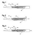
- FIGS. 1 through 3 Some systems and techniques to extend a guidewire laterally into the side vessel include a delivery system having the nose cone dilator shown in FIGS. 1 through 3 .
- a delivery system having the nose cone dilator shown in FIGS. 1 through 3 .
- FIG. 1 of the drawings accompanying the present description the proximal end 100 of the delivery device is shown.
- the device includes a nose cone dilator 102 having a groove formed into the nose cone dilator 102.
- a curved pre-loading guiding catheter 106 and a guide-wire 108 shown in FIG. 3 ).
- the curved guiding catheter 106 is disposed in a groove 104 formed into the nose cone dilator 102 and is biased to extend laterally such that its natural position directs the guidewire 108 in a specific direction (e.g., toward the contralateral iliac for an iliac branch device).
- the guide-wire 108 can then be extended laterally through the curved guiding catheter 102 when the nose cone dilator 102 is in place, thereby facilitating snaring the guidewire and a creating a through-wire for device alignment and/or facilitating the delivery of a bridging stent.
- a retractable sheath 110 is disposed over a portion of the dilator tip.
- the curved guiding catheter 106 is not constrained and extends from the nose cone dilator 102 during sterilization and shipping. This allows the curved guiding catheter 106 to retain its curved shaped following sterilization and storage. If the curved guiding catheter 106 were to be constrained to a straight shape during sterilization and shipping, there is a potential that the curved guiding catheter 106 could lose its curved shape.
- the sheath 110 is advanced over the curved guiding catheter 106 to constrain the curved guiding catheter 106 such that it no longer extends outside of the sheath 110. If the curved guiding catheter 106 were to remain extended from the nose cone dilator 102 during delivery, it is possible that the curved guiding catheter 106 could be damaged or interfere with the guidance of the delivery system.
- the sheath 110 is retracted distally and the curved guiding catheter 106 returns to its natural shape extending laterally from the nose cone dilator 102.
- the guidewire 108 can then be extended laterally.
- Preparing such a delivery system requires at least one additional step. Because the proximal most part of the guiding catheter must retain its curved shape, at least part of it must protrude from the main body tip outside of the sheath for shipping and storage. This ensures that the pre-formed curve will be maintained. Hence prior to inserting the delivery system, the sheath 110 must be advanced over the curved guiding catheter 106 tip to completely sheath it. As described above, the delivery system cannot be packaged with the sheath 110 restraining the curved guiding catheter 106, as the curved guiding catheter 106 may lose its shape over time. Furthermore, the curved tip must be re-sheathed so that it is protected as it advances through the body vessel.
- aspects of the invention seek to provide an improved delivery system.
- a delivery system for a medical device comprising: a first catheter having a distal end, a proximal end, and a longitudinal axis; a nose cone dilator disposed at the proximal end of the first catheter, the nose cone dilator having a groove formed in an outer surface of the nose cone dilator, the groove having a distal portion parallel to the longitudinal axis and a proximal portion extending circumferentially about the outer surface; and a second catheter, pre-loaded in the delivery system, and having a proximal end and a distal end, the second catheter proximal end being disposed in at least the proximal portion of the groove and extending from the proximal portion of the groove to the distal portion of the groove.
- a delivery system for a medical device comprising: a delivery catheter having a proximal tip and a longitudinal axis; a groove disposed in an exterior surface of the proximal tip, the groove having a distal portion parallel to the longitudinal axis and a proximal portion extending circumferentially about the proximal tip; a sheath disposed at least partially over the proximal tip and the groove, the sheath slidable in a longitudinal direction relative to the delivery catheter from a first position to a second position; and a pre-loaded guiding catheter extending a length of the delivery catheter and disposed in the groove.
- the delivery system preferably further comprises a branched stent graft disposed on the delivery catheter and within the sheath, and having a proximal end and a distal end, the branched stent graft having a lumen and a side branch extending from the stent graft between the proximal end and the distal end.
- the pre-loaded guiding catheter extends from the side branch into the distal portion of the groove.
- the groove has a bottom surface that extends to the outer surface of the proximal tip.
- the guiding catheter is constrained within the groove with the sheath in the second position exposing a portion of the groove.
- a method of delivering a guidewire comprising:
- the guiding catheter remains at least partially in the groove when the sheath is moved to the second position.
- the guiding catheter remains at least partially in the groove when the guidewire is extended from the guiding catheter.
- the second position releases the fenestrated stent graft.
- the delivery system includes a first catheter, a nose cone dilator, and a second catheter.
- the first catheter has a distal end, a proximal end, and a longitudinal axis.
- the nose cone dilator is disposed at the proximal end of the first catheter and has a groove formed on an outer surface of the nose cone dilator.
- the groove may have a distal portion parallel to the longitudinal axis and a proximal portion extending circumferentially about the outer surface.
- the groove may be helical or substantially helical.
- the second catheter has a proximal end and a distal end. The second catheter proximal end is constrained within the groove and extends from the distal portion of the groove to the proximal portion of the groove.
- the second catheter is pre-loaded in the delivery system and is part of the delivery system as introduced into a patient.
- a delivery system in another example, includes a delivery catheter, a sheath, and a pre-loaded guiding catheter.
- the delivery catheter has a proximal tip and a longitudinal axis.
- a groove is disposed on an exterior surface of the proximal tip and the groove has a distal portion parallel to the longitudinal axis and a proximal portion extending circumferentially about the outer surface.
- the sheath is disposed about a portion of the delivery catheter and at least partially over the groove and is slidable in a longitudinal direction relative to the delivery catheter from a first position to a second position.
- the guiding catheter extends a length of the delivery catheter and is constrained within the groove by the sheath in the first position.
- Embodiments of the invention also provide a method of delivering a guidewire including accessing a delivery system, introducing the delivery system into a vessel lumen, moving the sheath from the first position to the second position, and extending the guidewire from the guiding catheter lateral relative to the delivery catheter.
- the delivery system accessed includes a delivery catheter having a proximal tip, a groove disposed in a surface of the proximal tip, the groove having a distal portion parallel to a longitudinal axis of the catheter and a proximal circumferential portion, a sheath covering the groove, the sheath movable from a first position covering the groove to a second position at which a proximal portion of the groove in uncovered, a fenestrated stent graft disposed between the sheath in the first position and the delivery catheter, the fenestrated stent graft having a side branch, a guiding catheter extending from the side branch into the proximal portion of the groove, and a guidewire disposed in the guiding catheter.
- proximal refers to a direction that is generally closest to the heart during a medical procedure
- distal refers to a direction that is furthest from the heart during a medical procedure.
- proximal end of the device is that part that is inserted into a patient and the distal end is that part that remains outside of the patient.
- stent means any device or structure that provides, or is configured to provide, rigidity, expansion force, or support to a body part (e.g., a diseased, damaged, or otherwise compromised body lumen.).
- a stent may comprise any suitable material, including, but not limited to, biocompatible metals and plastics. Examples of suitable materials include metals such as stainless steel and NITINOL, and plastics such as polyethylene terephthalate (“PET”), polytetrafluoroethylene (“PTFE”) and polyurethane.
- PET polyethylene terephthalate
- PTFE polytetrafluoroethylene
- a stent may be "expandable,” that is, it may be capable of being expanded from a constricted configuration to an expanded configuration.
- a stent may be self-expanding and expand by virtue of its own resilience.
- a stent may be pressure-expandable and expand only upon the application of an external force.
- a stent may be expandable upon application of heat, such as when exposed to body temperature.
- An example of a self-expanding stent is the Z-STENT®, which is available from Cook Incorporated, Bloomington, Indiana, USA.
- lumen describes a cavity or channel within a tube or a tubular body, such as body vessel.
- endoluminal means within a lumen, and can refer to objects that are found or that can be placed within a lumen, or methods or processes that occur within a lumen.
- pre-loaded means in place in the delivery system prior to use of the device on the patient.
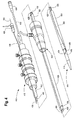
- the delivery system 410 includes a handle portion 412 and a deployable portion 414 which is deployed into a patient during an endovascular procedure.
- the deployable portion 414 comprises a nose cone dilator 416 with a curved groove 418 formed on its outer surface.
- a sheath 420 extends from a sheath hub 422 to the nose cone dilator 416.
- the sheath 420 has been partially retracted by retraction of the hub 422 to show a curved tip 424 of a guiding catheter 426.
- the guiding catheter 426 extends from the nose cone dilator 416 to a hemostatic seal 429 adjacent to the handle 412 of the delivery system 410.
- the guiding catheter 426 extends through a hemostatic seal 429 within the handle 412 and a lumen 431 of a delivery catheter 430.
- the lumen 431 extends through the guiding catheter 426 so that an auxiliary guidewire 442 may be deployed there through.
- the delivery catheter 430 extends from the handle 412 through the hub 422 and terminates distally of the nose cone dilator 416.
- a main guidewire catheter 432 extends from a syringe hub 434 through the rear of the handle 412 through the lumen 431 of the delivery catheter 430 to the nose cone dilator 416.
- the guiding catheter 426 extends through the lumen 431 in the delivery catheter 430 and then extends out of the rear of the handle 412.
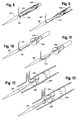
- FIG. 5 depicts a nose cone dilator 500 having a curved groove 506 for receiving a guiding catheter (not shown).
- the curved groove 506 is disposed in the outer surface of the nose cone dilator 500.
- a distal end 510 of the curved groove 506 is substantially parallel to a longitudinal axis of the nose cone dilator 500.
- a proximal end 512 of the curved groove 506 extends at least partially circumferentially about the outer surface and may be orthogonal to the longitudinal axis.
- the curved groove 506 follows a path similar to a portion of a helix as it extends around the surface of the nose cone dilator 500.
- the curved groove 506 may be substantially "U” shaped in cross section to receive a guiding catheter (not shown).
- the curved groove 506 shapes the guiding catheter to have a longitudinal orientation at the distal end 510 of the curved groove 506 to a circumferential orientation 506 at the proximal end 510 of the groove.
- the curved groove 506 has a bottom surface that extends outward to join the outer surface of the nose cone dilator 500.
- FIG. 6 depicts the nose cone dilator 500 of FIG. 5 with a retractable sheath 602 in place over the curved groove 506.
- a guiding catheter 604 is disposed in the curved groove 506 between the nose cone dilator 500 and the retractable sheath 602.
- the delivery system is ready to be packaged with the guiding catheter 604 in place, constrained from movement by the retractable sheath 602. Because the curved groove 506 is curved complementary to the curve of the guiding catheter 604, there is not a danger of the guiding catheter 604 losing its curve during packaging and sterilization.
- the delivery system may be introduced into a vascular system with the nose cone dilator 500 in the configuration shown in FIG. 6 .
- the delivery system is introduced in a vessel in this state and guided to a deployment location.
- FIG. 7 illustrates the nose cone dilator 500 with the retractable sheath 602 partially retracted once the delivery system in place.
- the retractable sheath 602 is partially retracted such that the proximal portion 512 of the curved groove 506 is uncovered, thereby exposing the guiding catheter 604.
- a guidewire 702 is shown exiting the guiding catheter 604 in a direction extending away from the longitudinal axis of the delivery system in a circumferential direction. Since no constraint is provided to the guidewire 702 once it exits the guiding catheter 604, the guidewire 702 extends straight laterally from the delivery system.
- the delivery system may be rotated to position the guiding catheter 604 at a desired orientation.
- the distal end of the delivery system may be rotated to orient the guiding catheter 604.
- the delivery system may be auto orientating such that the guiding catheter 604 naturally aligns to a predicable location.
- a curved cannula in an arch would auto align a general curve of the cannula with a curve of the arch.
- the guiding catheter 604 may extend substantially orthogonal to the longitudinal axis of the delivery system. The guiding catheter 604 may remain in the curved groove 506 while the guidewire 702 is extended from the guiding catheter 604.
- the partially retracted retractable sheath 604 may cover the distal portion of the groove constraining the guiding catheter within the groove. Because the extension of the guidewire 702 may occur without any movement by the guiding catheter 604, the guidewire 702 may be extended even if the delivery system is against a vessel wall.
- FIG. 8 illustrates the proper placement of the guiding catheter 604.
- a distal portion 802 of the guiding catheter 604 is on the same side of the nose cone dilator 500 as the curved groove 506.
- FIG. 9 illustrates improper placement of the guiding catheter 604.
- a distal portion 902 of the guiding catheter 604 is opposite the curved groove 506 of the nose cone dilator 500.
- FIG. 10 illustrates the delivery system with the sheath (not shown) partially retracted such that a stent graft 1000 is partially expanded.
- the guiding catheter 604 exits the stent graft 1000 through a side arm 1002 and curves away from the axis of the nose cone dilator 500.
- the guidewire 702 exits the guiding catheter 604 and extends away from the delivery system.
- FIG. 11 illustrates the delivery system with the improperly positioned guiding catheter 604 of FIG. 9 .
- the sheath (not shown) is partially retracted allowing the stent graft 1000 to expand partially.
- the guiding catheter 604 exits the stent graft 1000 through the side arm 1002 and wraps around the nose cone dilator 500.
- the guiding catheter 604 then extends away from the axis of the nose cone dilator 500.
- the guidewire 702 exits the guiding catheter 604 like in FIG. 10 ; however, the guiding catheter 604 and guidewire 702 are wrapped around the nose cone dilator 500. While the end result is the guidewire 702 extending laterally from the delivery system as intended, the sharpened radius of curvature of the guiding catheter 604 makes it difficult to extend the guidewire 702, and as will be shown in FIG. 13 , and may cause additional complications.
- FIG. 12 a fully deployed branched stent 1000 is illustrated.
- the nose cone dilator 500 exits out a main lumen 1202 of the branched stent 1000, while the guiding catheter 604 and guidewire 702 exit the branched stent 1000 through the side branch 1002.
- a user can now guide a leg extension (not shown) through the side branch 1002 and into position in the side vessel.
- FIG. 13 illustrates an improperly positioned guiding catheter 604 that wraps around the nose cone dilator 500 disrupting the path from the side branch 1002 to the side vessel. If the guiding catheter 604 is positioned incorrectly as in FIGS. 9, 11, and 13 , a leg extension likely cannot be guided into the side vessel through the branched stent 1000.
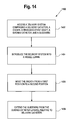
- FIG. 14 is a flow chart illustrating a method 1400 of introducing a guidewire.
- the method begins with block 1402 wherein a user accesses a delivery system.
- the delivery system includes a delivery catheter having a proximal tip, a groove disposed in an exterior surface of the proximal tip, the groove having a distal portion parallel to a longitudinal axis of the delivery catheter and a proximal circumferential portion, a sheath covering the groove, the sheath movable from a first position covering the groove to a second position at which a proximal portion of the groove is uncovered, and a branched stent graft disposed between the sheath in the first position and the delivery catheter, the branched stent graft having a side branch, a guiding catheter extending from the side branch into the proximal portion of the groove, and a guidewire disposed in the guiding catheter.
- Examples of the delivery system being accessed by the user include when a user opens a package containing the delivery system, a user assembling the delivery system, the delivery system being assembled for the user, or any other act that results in the user accessing the delivery system.
- block 1402 may include a user opening a package containing the delivery system 410 of FIG. 4 .
- the user introduces the delivery system into a vessel lumen.
- a user may introduce the delivery system 410 of FIG. 4 into a femoral artery of a patient.
- the user may cause the delivery system to be introduced into a vessel lumen.
- the user if the user is in control of the delivery system being introduced into a vessel lumen, it will be understood that this is the equivalent of the user introducing the delivery system into a vessel lumen.
- the user partially retracts the sheath of the delivery system exposing a portion of the guiding catheter.
- a user will be considered to have partially retracted the sheath if the user is in control of the retraction of the sheath.
- a user may retract the sheath hub 422 causing the sheath 420 to partially retract exposing a portion of the groove.
- the user can then extend the guidewire laterally from the catheter as indicated in block 1408.
- the user may advance guidewire 442 at the distal portion of delivery system 410 causing the guidewire 442 to extend from the guiding catheter 426.
- the guidewire 442 When the guidewire 442 is extended, the guiding catheter 426 will generally remain within the groove due to the constraint provided by the partially retracted sheath 420. As such, the guidewire 442 is able to extend without movement of the guiding catheter 426. In situations where a vessel wall is proximate the proximal tip 416 of the delivery system, the guidewire 442 may still be extended despite any interference between the vessel wall and the catheter.
- the method may further include fully retracting the sheath 420 to expose the groove in its entirety.
- the user may further retract the sheath hub 422 causing the sheath 420 to retract further thereby fully exposing the groove.
- the sheath 420 once fully retracted, no longer constrains the guiding catheter 426 within the groove and the guiding catheter 426 may then be released from the groove.
- the stent graft may be a fenestrated stent graft such as that shown in figures 15 to 19 and in application serial number 11/600,655 , which application is incorporated by reference herein in its entirety.
- Figures 15-19 repeat identical reference numbers when referring to like features illustrated in other drawings of US 11/600,655 .
- Reference number 60 is used to identify the fenestration formed in the stent graft illustrated in Figures 15-18 of the present application and reference number 64 is used to identify the side arm of the stent graft illustrated in Figure 19 of the present application.
- a pre-loaded catheter 10 may extend along side the exterior surface of a fenestrated stent graft 17, enter the lumen of the fenestrated stent graft 17 through a fenestration 60 in a side wall of the stent graft 17 and exit the proximal end of the stent graft 17.
- the pre-loaded catheter 10 is curved. Prior to deployment the proximal end 15 of the pre-loaded catheter 10 resides within the curved or helical groove 14 in the nose cone dilator 4 and is covered by the sheath 8.
- the pre-loaded catheter 10 enters the fenestrated stent graft 17 at the distal end, extends out of the fenestration 60 and toward the proximal end of the delivery device.
- the pre-loaded catheter 10 is curved. Prior to deployment the proximal end 15 of the pre-loaded catheter 10 resides within the curved or helical groove 14 in the nose cone dilator and is covered by the sheath 8.
- the stent graft may have more than one fenestration, and/or one or more side branches.
- the term "fenestration" may include an opening through which a side branch stent graft may be placed, and may also refer to a side branch that is integral with the stent graft and/or removably attached thereto, for example as shown in figure 19 , which otherwise corresponds to the embodiment of figures 15 and 16 .
- the stent graft may have at least two fenestrations.
- each fenestration is provided with its own pre-loaded catheter.
- the pre-loaded catheters accommodate guide wires to cannulate respective vessel branches, such as the renal arteries.
- a separate branch stent graft may be delivered via a separate delivery system through each of the fenestrations and into the branch vessel.
- FIG. 20 exemplifies a fenestrated stent graft system with a separately added side branch.
- FIG. 20 an exemplary composite stent graft according to an embodiment of the present invention is shown.
- the stent graft 2020 such as that shown in FIG. 8 of US 13/740,662 may be a proximal component 2100 of a composite stent grafting system as set forth with regard to Figures 21-23 of US 13/740,662 .
- the proximal component 2100 (from Figure 8 of US 13/740,662 ) has a proximal end, a distal end, tubular graft material and one or more stents either on the inside, outside, or both of the tubular graft material.
- Proximal component 2100 also has a fenestration or opening 2103 in the sidewall of the tubular graft material 2100 and a scallop 2105 in the proximal edge 2107 of the proximal component 2100.
- the distal component 2102 has a proximal end and may be bifurcated at the distal end, as shown in FIG. 20 attached hereto, although it may be a single tube.
- distal component 2102 has a graft body portion 2124, a short leg 2130, a long leg 2126 and may have internal or external stents.
- a leg extension 2104 having a proximal end 2139 and a distal end 2141 may be inserted into either the short leg 2130 or long leg 2126.
- the proximal end 2139 of the leg extension 2104 may be inserted into the short leg 2130.
- the leg extensions and the distal component may have one or more internal and/or external stents 2112.
- a branch device 2200 is provided and is configured for insertion into fenestration 2103 and a corresponding body branch vessel (not shown).
- Branch device 2200 may be a tube of graft material 2202 and may have one or more supporting stents 2204 which may be internal and/or external to the graft tube.
- the branch device 2200 may be inserted into the fenestration 2103 as shown in FIG. 18 of US 13/740,662 and the proximal end 2206 of the branch device 2200 may be flared about the internal periphery of the fenestration as shown in FIG. 18 of US 13/740,662 . Further details of accompanying Figure 20 can be found in US application number 13/740,662 , which is specifically incorporated herein by reference in its entirety, where figure 24 corresponds to present figure 20 .
Landscapes
- Health & Medical Sciences (AREA)
- Engineering & Computer Science (AREA)
- Biomedical Technology (AREA)
- Cardiology (AREA)
- Oral & Maxillofacial Surgery (AREA)
- Transplantation (AREA)
- Heart & Thoracic Surgery (AREA)
- Vascular Medicine (AREA)
- Life Sciences & Earth Sciences (AREA)
- Animal Behavior & Ethology (AREA)
- General Health & Medical Sciences (AREA)
- Public Health (AREA)
- Veterinary Medicine (AREA)
- Gastroenterology & Hepatology (AREA)
- Pulmonology (AREA)
- Media Introduction/Drainage Providing Device (AREA)
- Prostheses (AREA)
Abstract
Description
- This invention relates to medical devices and, in particular, to devices, systems, and methods for delivery of a medical device into the human or animal vasculature by endovascular technique, and is particularly suited to deploying a stent graft where it may be necessary to catheterize a side branch vessel from a main vessel, for example, catheterizing the iliac artery from a contralateral iliac artery in order to deploy a stent graft. However, the invention is not limited to this example and may be utilized in any lumen where such catheterization is required.
- Stent grafts are used to treat the vasculature in a human body or an animal body to repair or bypass a defect in the vasculature. For instance, a stent graft may be used to span an aneurism in an artery. In some instances, however, such a damaged or defective portion of the artery may include a branch vessel such as an internal iliac artery. A stent graft spanning the length of the aneurism may cause further complications if the stent graft does not provide blood flow into the branch vessel. To provide blood flow into the branch vessel, a side branch on a branched stent graft or fenestrated stent graft can be positioned over the opening to the side vessel and then another stent graft can be deployed through the side branch or the fenestration into the side vessel. Blood can then flow through the branched stent graft into the branch vessel through the side branch.
- Using the Seldinger technique, a branched stent graft can be deployed into the common iliac artery by way of the femoral artery. During the positioning of the branched stent graft, it is necessary to align the side branch with the side vessel. A leg extension is then placed in the side vessel through the side branch. To align the branched stent graft and place the leg extension, it is beneficial to use a guidewire extending through the side branch and laterally into the side vessel.
- Some systems and techniques to extend a guidewire laterally into the side vessel include a delivery system having the nose cone dilator shown in
FIGS. 1 through 3 . One example of a similar system is shown inU.S. Publication No. 2009-0105801 A1 , incorporated herein by reference in its entirety. InFIG. 1 of the drawings accompanying the present description, theproximal end 100 of the delivery device is shown. The device includes anose cone dilator 102 having a groove formed into thenose cone dilator 102. A curvedpre-loading guiding catheter 106 and a guide-wire 108 (shown inFIG. 3 ). The curved guidingcatheter 106 is disposed in agroove 104 formed into thenose cone dilator 102 and is biased to extend laterally such that its natural position directs theguidewire 108 in a specific direction (e.g., toward the contralateral iliac for an iliac branch device). The guide-wire 108 can then be extended laterally through the curved guidingcatheter 102 when thenose cone dilator 102 is in place, thereby facilitating snaring the guidewire and a creating a through-wire for device alignment and/or facilitating the delivery of a bridging stent. As shown, aretractable sheath 110 is disposed over a portion of the dilator tip. - In
FIG. 1 , the curved guidingcatheter 106 is not constrained and extends from thenose cone dilator 102 during sterilization and shipping. This allows the curved guidingcatheter 106 to retain its curved shaped following sterilization and storage. If the curved guidingcatheter 106 were to be constrained to a straight shape during sterilization and shipping, there is a potential that the curved guidingcatheter 106 could lose its curved shape. - As shown in
FIG. 2 , when the delivery system is ready for use, thesheath 110 is advanced over the curved guidingcatheter 106 to constrain the curved guidingcatheter 106 such that it no longer extends outside of thesheath 110. If the curved guidingcatheter 106 were to remain extended from thenose cone dilator 102 during delivery, it is possible that the curved guidingcatheter 106 could be damaged or interfere with the guidance of the delivery system. - Once the device is delivered to the desired treatment site as shown in
FIG. 3 , thesheath 110 is retracted distally and the curved guidingcatheter 106 returns to its natural shape extending laterally from thenose cone dilator 102. Theguidewire 108 can then be extended laterally. - Preparing such a delivery system requires at least one additional step. Because the proximal most part of the guiding catheter must retain its curved shape, at least part of it must protrude from the main body tip outside of the sheath for shipping and storage. This ensures that the pre-formed curve will be maintained. Hence prior to inserting the delivery system, the
sheath 110 must be advanced over the curved guidingcatheter 106 tip to completely sheath it. As described above, the delivery system cannot be packaged with thesheath 110 restraining the curved guidingcatheter 106, as the curved guidingcatheter 106 may lose its shape over time. Furthermore, the curved tip must be re-sheathed so that it is protected as it advances through the body vessel. - Aspects of the invention seek to provide an improved delivery system.
- According to an aspect of the invention, there is provided a delivery system as in claim 1.
- According to an aspect of the invention, there is provided a delivery system for a medical device comprising: a first catheter having a distal end, a proximal end, and a longitudinal axis; a nose cone dilator disposed at the proximal end of the first catheter, the nose cone dilator having a groove formed in an outer surface of the nose cone dilator, the groove having a distal portion parallel to the longitudinal axis and a proximal portion extending circumferentially about the outer surface; and a second catheter, pre-loaded in the delivery system, and having a proximal end and a distal end, the second catheter proximal end being disposed in at least the proximal portion of the groove and extending from the proximal portion of the groove to the distal portion of the groove.
- According to an aspect of the invention, there is provided a delivery system for a medical device comprising: a delivery catheter having a proximal tip and a longitudinal axis; a groove disposed in an exterior surface of the proximal tip, the groove having a distal portion parallel to the longitudinal axis and a proximal portion extending circumferentially about the proximal tip; a sheath disposed at least partially over the proximal tip and the groove, the sheath slidable in a longitudinal direction relative to the delivery catheter from a first position to a second position; and a pre-loaded guiding catheter extending a length of the delivery catheter and disposed in the groove.
- The delivery system preferably further comprises a branched stent graft disposed on the delivery catheter and within the sheath, and having a proximal end and a distal end, the branched stent graft having a lumen and a side branch extending from the stent graft between the proximal end and the distal end.
- Preferably, the pre-loaded guiding catheter extends from the side branch into the distal portion of the groove.
- Preferably, the groove has a bottom surface that extends to the outer surface of the proximal tip.
- Preferably, the guiding catheter is constrained within the groove with the sheath in the second position exposing a portion of the groove.
- According to an aspect of the invention, there is provided a method of delivering a guidewire comprising:
- accessing a delivery system comprising:
- a delivery catheter having a proximal tip;
- a groove disposed in a surface of the proximal tip, the groove having a distal portion parallel to a longitudinal axis of the catheter and a proximal circumferential portion;
- a sheath covering the groove, the sheath movable from a first position covering the groove to a second position at which a proximal portion of the groove in uncovered;
- a fenestrated stent graft disposed between the sheath and the delivery catheter, the fenestrated stent graft having a side branch extending from the fenestrated stent graft between a proximal end and distal end of the fenestrated stent graft;
- a guiding catheter extending from the side branch into the proximal portion of the groove; and
- a guidewire disposed in the guiding catheter; introducing the delivery system into a vessel lumen;
- moving the sheath from the first position to the second position exposing a portion of the groove and guiding catheter; and
- extending the guidewire from the guiding catheter lateral relative to the delivery catheter.
- Preferably, the guiding catheter remains at least partially in the groove when the sheath is moved to the second position.
- Preferably, the guiding catheter remains at least partially in the groove when the guidewire is extended from the guiding catheter.
- Preferably, the second position releases the fenestrated stent graft.
- Embodiments of the present invention provide for a delivery system for a medical device. In one embodiment, the delivery system includes a first catheter, a nose cone dilator, and a second catheter. The first catheter has a distal end, a proximal end, and a longitudinal axis. The nose cone dilator is disposed at the proximal end of the first catheter and has a groove formed on an outer surface of the nose cone dilator. The groove may have a distal portion parallel to the longitudinal axis and a proximal portion extending circumferentially about the outer surface. The groove may be helical or substantially helical. The second catheter has a proximal end and a distal end. The second catheter proximal end is constrained within the groove and extends from the distal portion of the groove to the proximal portion of the groove. The second catheter is pre-loaded in the delivery system and is part of the delivery system as introduced into a patient.
- In another example, a delivery system includes a delivery catheter, a sheath, and a pre-loaded guiding catheter. The delivery catheter has a proximal tip and a longitudinal axis. A groove is disposed on an exterior surface of the proximal tip and the groove has a distal portion parallel to the longitudinal axis and a proximal portion extending circumferentially about the outer surface. The sheath is disposed about a portion of the delivery catheter and at least partially over the groove and is slidable in a longitudinal direction relative to the delivery catheter from a first position to a second position. The guiding catheter extends a length of the delivery catheter and is constrained within the groove by the sheath in the first position.
- Embodiments of the invention also provide a method of delivering a guidewire including accessing a delivery system, introducing the delivery system into a vessel lumen, moving the sheath from the first position to the second position, and extending the guidewire from the guiding catheter lateral relative to the delivery catheter. The delivery system accessed includes a delivery catheter having a proximal tip, a groove disposed in a surface of the proximal tip, the groove having a distal portion parallel to a longitudinal axis of the catheter and a proximal circumferential portion, a sheath covering the groove, the sheath movable from a first position covering the groove to a second position at which a proximal portion of the groove in uncovered, a fenestrated stent graft disposed between the sheath in the first position and the delivery catheter, the fenestrated stent graft having a side branch, a guiding catheter extending from the side branch into the proximal portion of the groove, and a guidewire disposed in the guiding catheter.
- To further clarify the above and other advantages and features of embodiments of the present invention, reference to specific embodiments thereof are illustrated in the appended drawings. The drawings are exemplary and therefore not to be considered limiting.
-
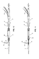
FIG. 1 depicts a nose cone dilator of a delivery system as packaged for shipping with a curved guiding catheter and a retracted sheath. -
FIG. 2 depicts the nose cone dilator ofFIG. 1 for insertion into a vessel with the sheath advanced to restrain and completely cover the curved guiding catheter. -
FIG. 3 depicts the nose cone dilator ofFIG. 1 , post-delivery, with the sheath retracted allowing the curved guiding catheter to extend laterally. -
FIG. 4 depicts an exemplary delivery system for a stent graft prosthesis. -
FIG. 5 depicts an exemplary nose cone dilator having a curved groove for receiving a curved guiding catheter. -
FIG. 6 depicts the nose cone dilator ofclaim 5 with the curved guiding catheter received in the curved groove. -
FIG. 7 depicts the nose cone dilator ofclaim 5 with a guidewire extending laterally from the nose cone dilator. -
FIG. 8 depicts an exemplary nose cone dilator with a properly positioned curved guiding catheter. -
FIG. 9 depicts an exemplary nose cone dilator with an improperly positioned curved guiding catheter. -
FIG.10 depicts a partially deployed branched stent with a properly positioned curved guiding catheter. -
FIG.11 depicts a partially deployed branched stent with an improperly positioned curved guiding catheter. -
FIG. 12 depicts a deployed branched stent with a properly positioned curved guiding catheter. -
FIG. 13 depicts a deployed branched stent with an improperly positioned curved guiding catheter. -
FIG. 14 depicts a flow chart of a method for placing a guidewire in a delivery system. -
FIG. 15 is a side view of a stent graft having a fenestration formed therein and an indwelling catheter extending outside of the graft distal to the fenestration. -
FIG. 16 is a top view of the stent graft ofFIG. 15 . -
FIG. 17 is a side view of another example of a stent graft having a fenestration formed therein and an indwelling catheter extending inside of the graft lumen distal to the fenestration. -
FIG. 18 is a top view of the stent graft ofFIG. 17 . -
FIG. 19 is a side view of one example of a stent graft having a side arm. -
FIG. 20 depicts a stent graft in which a side branch stent graft is delivered through a fenestration. - In the present application, the term "proximal" refers to a direction that is generally closest to the heart during a medical procedure, while the term "distal" refers to a direction that is furthest from the heart during a medical procedure. For further clarity, in the present case, the proximal end of the device is that part that is inserted into a patient and the distal end is that part that remains outside of the patient.
- The term "stent" means any device or structure that provides, or is configured to provide, rigidity, expansion force, or support to a body part (e.g., a diseased, damaged, or otherwise compromised body lumen.). A stent may comprise any suitable material, including, but not limited to, biocompatible metals and plastics. Examples of suitable materials include metals such as stainless steel and NITINOL, and plastics such as polyethylene terephthalate ("PET"), polytetrafluoroethylene ("PTFE") and polyurethane.
- A stent may be "expandable," that is, it may be capable of being expanded from a constricted configuration to an expanded configuration. A stent may be self-expanding and expand by virtue of its own resilience. Alternatively, a stent may be pressure-expandable and expand only upon the application of an external force. In addition, a stent may be expandable upon application of heat, such as when exposed to body temperature. An example of a self-expanding stent is the Z-STENT®, which is available from Cook Incorporated, Bloomington, Indiana, USA.
- The term "lumen" describes a cavity or channel within a tube or a tubular body, such as body vessel. The term "endoluminal" means within a lumen, and can refer to objects that are found or that can be placed within a lumen, or methods or processes that occur within a lumen.
- The term "pre-loaded" means in place in the delivery system prior to use of the device on the patient.
- Turning to
FIG. 4 , adelivery system 410 is shown. Thedelivery system 410 includes ahandle portion 412 and adeployable portion 414 which is deployed into a patient during an endovascular procedure. Thedeployable portion 414 comprises anose cone dilator 416 with acurved groove 418 formed on its outer surface. Asheath 420 extends from asheath hub 422 to thenose cone dilator 416. InFIG.4 , thesheath 420 has been partially retracted by retraction of thehub 422 to show acurved tip 424 of a guidingcatheter 426. - The guiding
catheter 426 extends from thenose cone dilator 416 to ahemostatic seal 429 adjacent to thehandle 412 of thedelivery system 410. The guidingcatheter 426 extends through ahemostatic seal 429 within thehandle 412 and alumen 431 of adelivery catheter 430. Thelumen 431 extends through the guidingcatheter 426 so that anauxiliary guidewire 442 may be deployed there through. Thedelivery catheter 430 extends from thehandle 412 through thehub 422 and terminates distally of thenose cone dilator 416. Amain guidewire catheter 432 extends from asyringe hub 434 through the rear of thehandle 412 through thelumen 431 of thedelivery catheter 430 to thenose cone dilator 416. - Proceeding distally along the length of the
delivery system 410, the guidingcatheter 426 extends through thelumen 431 in thedelivery catheter 430 and then extends out of the rear of thehandle 412. -
FIG. 5 depicts anose cone dilator 500 having acurved groove 506 for receiving a guiding catheter (not shown). Thecurved groove 506 is disposed in the outer surface of thenose cone dilator 500. Adistal end 510 of thecurved groove 506 is substantially parallel to a longitudinal axis of thenose cone dilator 500. Aproximal end 512 of thecurved groove 506 extends at least partially circumferentially about the outer surface and may be orthogonal to the longitudinal axis. In some embodiments, thecurved groove 506 follows a path similar to a portion of a helix as it extends around the surface of thenose cone dilator 500. Thecurved groove 506 may be substantially "U" shaped in cross section to receive a guiding catheter (not shown). Thecurved groove 506 shapes the guiding catheter to have a longitudinal orientation at thedistal end 510 of thecurved groove 506 to acircumferential orientation 506 at theproximal end 510 of the groove. Thecurved groove 506 has a bottom surface that extends outward to join the outer surface of thenose cone dilator 500. -
FIG. 6 depicts thenose cone dilator 500 ofFIG. 5 with aretractable sheath 602 in place over thecurved groove 506. A guidingcatheter 604 is disposed in thecurved groove 506 between thenose cone dilator 500 and theretractable sheath 602. In this state, the delivery system is ready to be packaged with the guidingcatheter 604 in place, constrained from movement by theretractable sheath 602. Because thecurved groove 506 is curved complementary to the curve of the guidingcatheter 604, there is not a danger of the guidingcatheter 604 losing its curve during packaging and sterilization. - The delivery system may be introduced into a vascular system with the
nose cone dilator 500 in the configuration shown inFIG. 6 . In contrast to the conventional delivery systems described previously, there is no need for a user to first advance thesheath 602 over the guidingcatheter 604, since the delivery system is packaged with the guidingcatheter 604 already sheathed. The delivery system is introduced in a vessel in this state and guided to a deployment location. - Once the delivery system is in place at the deployment location, the user may partially retract the
retractable sheath 602.FIG. 7 illustrates thenose cone dilator 500 with theretractable sheath 602 partially retracted once the delivery system in place. InFIG. 7 theretractable sheath 602 is partially retracted such that theproximal portion 512 of thecurved groove 506 is uncovered, thereby exposing the guidingcatheter 604. Aguidewire 702 is shown exiting the guidingcatheter 604 in a direction extending away from the longitudinal axis of the delivery system in a circumferential direction. Since no constraint is provided to theguidewire 702 once it exits the guidingcatheter 604, theguidewire 702 extends straight laterally from the delivery system. The delivery system may be rotated to position the guidingcatheter 604 at a desired orientation. In embodiments in which the delivery system has a sufficient torsional rigidity, the distal end of the delivery system may be rotated to orient the guidingcatheter 604. In some embodiments, the delivery system may be auto orientating such that the guidingcatheter 604 naturally aligns to a predicable location. For example, a curved cannula in an arch would auto align a general curve of the cannula with a curve of the arch. In some embodiments, the guidingcatheter 604 may extend substantially orthogonal to the longitudinal axis of the delivery system. The guidingcatheter 604 may remain in thecurved groove 506 while theguidewire 702 is extended from the guidingcatheter 604. The partially retractedretractable sheath 604 may cover the distal portion of the groove constraining the guiding catheter within the groove. Because the extension of theguidewire 702 may occur without any movement by the guidingcatheter 604, theguidewire 702 may be extended even if the delivery system is against a vessel wall. - However, if the guiding
catheter 604 is placed in thecurved groove 506 improperly, the guidingcatheter 604 may wrap around the delivery system and cause complications.FIG. 8 illustrates the proper placement of the guidingcatheter 604. InFIG. 8 , adistal portion 802 of the guidingcatheter 604 is on the same side of thenose cone dilator 500 as thecurved groove 506.FIG. 9 illustrates improper placement of the guidingcatheter 604. InFIG. 9 , adistal portion 902 of the guidingcatheter 604 is opposite thecurved groove 506 of thenose cone dilator 500. -
FIG. 10 illustrates the delivery system with the sheath (not shown) partially retracted such that astent graft 1000 is partially expanded. The guidingcatheter 604 exits thestent graft 1000 through aside arm 1002 and curves away from the axis of thenose cone dilator 500. Theguidewire 702 exits the guidingcatheter 604 and extends away from the delivery system.FIG. 11 illustrates the delivery system with the improperly positioned guidingcatheter 604 ofFIG. 9 . Once again, the sheath (not shown) is partially retracted allowing thestent graft 1000 to expand partially. The guidingcatheter 604 exits thestent graft 1000 through theside arm 1002 and wraps around thenose cone dilator 500. The guidingcatheter 604 then extends away from the axis of thenose cone dilator 500. Theguidewire 702 exits the guidingcatheter 604 like inFIG. 10 ; however, the guidingcatheter 604 and guidewire 702 are wrapped around thenose cone dilator 500. While the end result is theguidewire 702 extending laterally from the delivery system as intended, the sharpened radius of curvature of the guidingcatheter 604 makes it difficult to extend theguidewire 702, and as will be shown inFIG. 13 , and may cause additional complications. - In
FIG. 12 , a fully deployed branchedstent 1000 is illustrated. Thenose cone dilator 500 exits out amain lumen 1202 of thebranched stent 1000, while the guidingcatheter 604 and guidewire 702 exit thebranched stent 1000 through theside branch 1002. A user can now guide a leg extension (not shown) through theside branch 1002 and into position in the side vessel.FIG. 13 illustrates an improperly positioned guidingcatheter 604 that wraps around thenose cone dilator 500 disrupting the path from theside branch 1002 to the side vessel. If the guidingcatheter 604 is positioned incorrectly as inFIGS. 9, 11, and 13 , a leg extension likely cannot be guided into the side vessel through thebranched stent 1000. -
FIG. 14 is a flow chart illustrating amethod 1400 of introducing a guidewire. The method begins withblock 1402 wherein a user accesses a delivery system. The delivery system includes a delivery catheter having a proximal tip, a groove disposed in an exterior surface of the proximal tip, the groove having a distal portion parallel to a longitudinal axis of the delivery catheter and a proximal circumferential portion, a sheath covering the groove, the sheath movable from a first position covering the groove to a second position at which a proximal portion of the groove is uncovered, and a branched stent graft disposed between the sheath in the first position and the delivery catheter, the branched stent graft having a side branch, a guiding catheter extending from the side branch into the proximal portion of the groove, and a guidewire disposed in the guiding catheter. Examples of the delivery system being accessed by the user include when a user opens a package containing the delivery system, a user assembling the delivery system, the delivery system being assembled for the user, or any other act that results in the user accessing the delivery system. For example, block 1402 may include a user opening a package containing thedelivery system 410 ofFIG. 4 . - In
block 1404, the user introduces the delivery system into a vessel lumen. For example, a user may introduce thedelivery system 410 ofFIG. 4 into a femoral artery of a patient. In some embodiments, the user may cause the delivery system to be introduced into a vessel lumen. For the purposes of this application, if the user is in control of the delivery system being introduced into a vessel lumen, it will be understood that this is the equivalent of the user introducing the delivery system into a vessel lumen. - In
block 1406, the user partially retracts the sheath of the delivery system exposing a portion of the guiding catheter. Again, a user will be considered to have partially retracted the sheath if the user is in control of the retraction of the sheath. Referring toFIG. 4 , a user may retract thesheath hub 422 causing thesheath 420 to partially retract exposing a portion of the groove. - With the sheath partially retracted, the user can then extend the guidewire laterally from the catheter as indicated in
block 1408. Referring again toFIG. 4 for example, the user may advance guidewire 442 at the distal portion ofdelivery system 410 causing theguidewire 442 to extend from the guidingcatheter 426. When theguidewire 442 is extended, the guidingcatheter 426 will generally remain within the groove due to the constraint provided by the partially retractedsheath 420. As such, theguidewire 442 is able to extend without movement of the guidingcatheter 426. In situations where a vessel wall is proximate theproximal tip 416 of the delivery system, theguidewire 442 may still be extended despite any interference between the vessel wall and the catheter. - The method may further include fully retracting the
sheath 420 to expose the groove in its entirety. For example, referring toFIG. 4 , the user may further retract thesheath hub 422 causing thesheath 420 to retract further thereby fully exposing the groove. Thesheath 420, once fully retracted, no longer constrains the guidingcatheter 426 within the groove and the guidingcatheter 426 may then be released from the groove. - The stent graft may be a fenestrated stent graft such as that shown in
figures 15 to 19 and in applicationserial number 11/600,655 Figures 15-19 repeat identical reference numbers when referring to like features illustrated in other drawings ofUS 11/600,655Reference number 60 is used to identify the fenestration formed in the stent graft illustrated inFigures 15-18 of the present application andreference number 64 is used to identify the side arm of the stent graft illustrated inFigure 19 of the present application. As shown infigures 15 and 16 attached hereto, apre-loaded catheter 10 may extend along side the exterior surface of afenestrated stent graft 17, enter the lumen of thefenestrated stent graft 17 through afenestration 60 in a side wall of thestent graft 17 and exit the proximal end of thestent graft 17. As shown, thepre-loaded catheter 10 is curved. Prior to deployment theproximal end 15 of thepre-loaded catheter 10 resides within the curved orhelical groove 14 in the nose cone dilator 4 and is covered by thesheath 8. In another embodiment, as shown infigures 17 and 18 , thepre-loaded catheter 10 enters thefenestrated stent graft 17 at the distal end, extends out of thefenestration 60 and toward the proximal end of the delivery device. As shown, thepre-loaded catheter 10 is curved. Prior to deployment theproximal end 15 of thepre-loaded catheter 10 resides within the curved orhelical groove 14 in the nose cone dilator and is covered by thesheath 8. In further embodiments, the stent graft may have more than one fenestration, and/or one or more side branches. The term "fenestration" may include an opening through which a side branch stent graft may be placed, and may also refer to a side branch that is integral with the stent graft and/or removably attached thereto, for example as shown infigure 19 , which otherwise corresponds to the embodiment offigures 15 and 16 . In one example, the stent graft may have at least two fenestrations. In such a case, each fenestration is provided with its own pre-loaded catheter. The pre-loaded catheters accommodate guide wires to cannulate respective vessel branches, such as the renal arteries. Thereafter, a separate branch stent graft may be delivered via a separate delivery system through each of the fenestrations and into the branch vessel.Figure 20 exemplifies a fenestrated stent graft system with a separately added side branch.
Referring now toFIG. 20 , an exemplary composite stent graft according to an embodiment of the present invention is shown. The stent graft 2020, such as that shown inFIG. 8 ofUS 13/740,662 proximal component 2100 of a composite stent grafting system as set forth with regard to Figures 21-23 ofUS 13/740,662 Figure 8 ofUS 13/740,662 Proximal component 2100 also has a fenestration oropening 2103 in the sidewall of thetubular graft material 2100 and ascallop 2105 in theproximal edge 2107 of theproximal component 2100. Thedistal component 2102 has a proximal end and may be bifurcated at the distal end, as shown inFIG. 20 attached hereto, although it may be a single tube. As shown,distal component 2102 has agraft body portion 2124, ashort leg 2130, along leg 2126 and may have internal or external stents. Aleg extension 2104 having aproximal end 2139 and adistal end 2141 may be inserted into either theshort leg 2130 orlong leg 2126. As shown inFIG. 20 attached hereto, theproximal end 2139 of theleg extension 2104 may be inserted into theshort leg 2130. The leg extensions and the distal component may have one or more internal and/orexternal stents 2112.
As shown inFIG. 20 attached hereto, abranch device 2200 is provided and is configured for insertion intofenestration 2103 and a corresponding body branch vessel (not shown).Branch device 2200 may be a tube ofgraft material 2202 and may have one or more supportingstents 2204 which may be internal and/or external to the graft tube. Thebranch device 2200 may be inserted into thefenestration 2103 as shown inFIG. 18 ofUS 13/740,662 proximal end 2206 of thebranch device 2200 may be flared about the internal periphery of the fenestration as shown inFIG. 18 ofUS 13/740,662 Figure 20 can be found inUS application number 13/740,662 figure 20 . - Throughout this specification, embodiments of the invention have been described in relation to a delivery catheter and a guiding catheter, but the invention is not limited to these particular catheters. Additionally, various indications have been given as to preferred and alternative embodiments of the invention. However, it should be understood that the invention is not limited to these embodiments. It is therefore intended that the foregoing detailed description be regarded as illustrative rather than limiting.
- All optional and preferred features and modifications of the described embodiments and dependent claims are usable in all aspects of the invention taught herein. Furthermore, the individual features of the dependent claims, as well as all optional and preferred features and modifications of the described embodiments are combinable and interchangeable with one another.
- The disclosures in United States patent application number
61/719,653
Claims (14)
- A delivery system for a medical device comprising:a first catheter having a distal end, a proximal end, and a longitudinal axis;a nose cone dilator disposed at the proximal end of the first catheter, the nose cone dilator having a groove formed in an outer surface of the nose cone dilator, the groove having a distal portion parallel to the longitudinal axis and a proximal portion extending circumferentially about the outer surface; anda second catheter, pre-loaded in the delivery system, and having a proximal end and a distal end, the second catheter proximal end being disposed in the groove.
- The delivery system of claim 1, wherein the second catheter proximal end is disposed in at least the proximal portion of the groove and extends from the proximal portion of the groove to the distal portion of the groove.
- The delivery system of claim 1 or 2, further comprising:a sheath disposed about the nose cone dilator proximate the groove, wherein the second catheter is constrained within the groove by the sheath.
- The delivery system of any preceding claim, wherein the groove is at least partially helical.
- The delivery system of any preceding claim, wherein the groove has a bottom surface that extends to the outer surface of the nose cone dilator.
- The delivery system of any preceding claim, further comprising:a branched stent graft retained on the proximal end of the first catheter and having a stent graft lumen and a side branch extending from the stent graft between the proximal and distal ends of the stent graft.
- The delivery system of claim 6 wherein the side branch is aligned with the distal portion of the groove.
- The delivery system of claim 6 wherein the side branch is aligned with the proximal portion of the groove.
- The delivery system of any of claims 6 to 8, wherein the second catheter extends through the stent graft lumen and through the side branch to the nose cone dilator.
- The delivery system of any preceding claim, wherein the proximal portion of the groove is substantially perpendicular to the longitudinal axis.
- The delivery system of any preceding claim, comprising:a sheath disposed at least partially over the nose cone dilator and the groove, the sheath slidable in a longitudinal direction relative to the delivery catheter from a first position to a second position;wherein the second catheter extends a length of the first catheter.
- The delivery system of claim 11 wherein the second catheter is constrained within the groove with the sheath in the second position exposing a portion of the groove.
- The delivery system of any preceding claim, wherein the groove has a bottom surface that extends to the outer surface of the nose cone dilator.
- The delivery system of any preceding claim, further comprising:a fenestrated stent graft retained on the first catheter, the fenestrated stent graft having proximal end, a distal end and a fenestration disposed between the proximal end and the distal end, where the second catheter is disposed through the fenestration.
Applications Claiming Priority (1)
| Application Number | Priority Date | Filing Date | Title |
|---|---|---|---|
| US201261719653P | 2012-10-29 | 2012-10-29 |
Publications (3)
| Publication Number | Publication Date |
|---|---|
| EP2724694A2 true EP2724694A2 (en) | 2014-04-30 |
| EP2724694A3 EP2724694A3 (en) | 2015-01-07 |
| EP2724694B1 EP2724694B1 (en) | 2016-12-21 |
Family
ID=49517447
Family Applications (1)
| Application Number | Title | Priority Date | Filing Date |
|---|---|---|---|
| EP13275267.6A Active EP2724694B1 (en) | 2012-10-29 | 2013-10-29 | Delivery system with curved preloaded catheter |
Country Status (2)
| Country | Link |
|---|---|
| US (1) | US9763817B2 (en) |
| EP (1) | EP2724694B1 (en) |
Cited By (3)
| Publication number | Priority date | Publication date | Assignee | Title |
|---|---|---|---|---|
| AU2015215913B1 (en) * | 2015-08-20 | 2016-02-25 | Cook Medical Technologies Llc | An endograft delivery device assembly |
| EP3064176A1 (en) * | 2015-03-05 | 2016-09-07 | Cook Medical Technologies LLC | Prosthesis delivery device |
| US10426646B2 (en) | 2015-03-05 | 2019-10-01 | Cook Medical Technologies Llc | Pre-loaded delivery device with tri-fold proximal prosthesis attachment |
Families Citing this family (31)
| Publication number | Priority date | Publication date | Assignee | Title |
|---|---|---|---|---|
| US8870950B2 (en) | 2009-12-08 | 2014-10-28 | Mitral Tech Ltd. | Rotation-based anchoring of an implant |
| US20110224785A1 (en) | 2010-03-10 | 2011-09-15 | Hacohen Gil | Prosthetic mitral valve with tissue anchors |
| US9763657B2 (en) | 2010-07-21 | 2017-09-19 | Mitraltech Ltd. | Techniques for percutaneous mitral valve replacement and sealing |
| US11653910B2 (en) | 2010-07-21 | 2023-05-23 | Cardiovalve Ltd. | Helical anchor implantation |
| US8852272B2 (en) | 2011-08-05 | 2014-10-07 | Mitraltech Ltd. | Techniques for percutaneous mitral valve replacement and sealing |
| US10376361B2 (en) | 2011-08-05 | 2019-08-13 | Cardiovalve Ltd. | Techniques for percutaneous mitral valve replacement and sealing |
| US11517429B2 (en) | 2011-08-05 | 2022-12-06 | Cardiovalve Ltd. | Apparatus for use at a heart valve |
| EP3417813B1 (en) | 2011-08-05 | 2020-05-13 | Cardiovalve Ltd | Percutaneous mitral valve replacement |
| EP2948103B1 (en) | 2013-01-24 | 2022-12-07 | Cardiovalve Ltd | Ventricularly-anchored prosthetic valves |
| EP3174502B1 (en) | 2014-07-30 | 2022-04-06 | Cardiovalve Ltd | Apparatus for implantation of an articulatable prosthetic valve |
| US10016293B2 (en) | 2014-12-29 | 2018-07-10 | Cook Medical Technologies Llc | Prosthesis delivery systems having an atraumatic tip for use with trigger wires |
| CA3162308A1 (en) | 2015-02-05 | 2016-08-11 | Cardiovalve Ltd. | Prosthetic valve with axially-sliding frames |
| US10058441B2 (en) * | 2015-05-20 | 2018-08-28 | Cook Medical Technologies Llc | Deployment handle for a pre-loaded iliac prosthesis delivery device |
| US10531866B2 (en) | 2016-02-16 | 2020-01-14 | Cardiovalve Ltd. | Techniques for providing a replacement valve and transseptal communication |
| US20190231525A1 (en) | 2016-08-01 | 2019-08-01 | Mitraltech Ltd. | Minimally-invasive delivery systems |
| CN120918849A (en) | 2016-08-10 | 2025-11-11 | 卡迪尔维尔福股份有限公司 | Prosthetic valve with coaxial frame |
| US12064347B2 (en) | 2017-08-03 | 2024-08-20 | Cardiovalve Ltd. | Prosthetic heart valve |
| US11246704B2 (en) | 2017-08-03 | 2022-02-15 | Cardiovalve Ltd. | Prosthetic heart valve |
| US11793633B2 (en) | 2017-08-03 | 2023-10-24 | Cardiovalve Ltd. | Prosthetic heart valve |
| US10888421B2 (en) | 2017-09-19 | 2021-01-12 | Cardiovalve Ltd. | Prosthetic heart valve with pouch |
| US10537426B2 (en) | 2017-08-03 | 2020-01-21 | Cardiovalve Ltd. | Prosthetic heart valve |
| US10575948B2 (en) | 2017-08-03 | 2020-03-03 | Cardiovalve Ltd. | Prosthetic heart valve |
| US12458493B2 (en) | 2017-09-19 | 2025-11-04 | Cardiovalve Ltd. | Prosthetic heart valve and delivery systems and methods |
| GB201720803D0 (en) | 2017-12-13 | 2018-01-24 | Mitraltech Ltd | Prosthetic Valve and delivery tool therefor |
| GB201800399D0 (en) | 2018-01-10 | 2018-02-21 | Mitraltech Ltd | Temperature-control during crimping of an implant |
| US10470797B1 (en) | 2018-07-17 | 2019-11-12 | SlipStream, LLC | Systems and methods for vascular access |
| WO2021007346A1 (en) | 2019-07-09 | 2021-01-14 | Juad Nextgen Neuroend, Llc | Apparatus, systems and methods for transvascular access to the brain |
| US11806523B2 (en) | 2020-06-30 | 2023-11-07 | Vonova Inc. | Transcatheter electrode array and use thereof |
| US12357459B2 (en) | 2020-12-03 | 2025-07-15 | Cardiovalve Ltd. | Transluminal delivery system |
| US20240225868A9 (en) * | 2021-02-22 | 2024-07-11 | W. L. Gore & Associates, Inc. | Multi-component delivery systems and methods |
| CN121667894A (en) * | 2025-12-15 | 2026-03-17 | 先健科技(深圳)有限公司 | Bracket system |
Citations (1)
| Publication number | Priority date | Publication date | Assignee | Title |
|---|---|---|---|---|
| US20090105801A1 (en) | 2007-10-23 | 2009-04-23 | William Cook Europe, Aps | Indwelling catheter arrangement |
Family Cites Families (12)
| Publication number | Priority date | Publication date | Assignee | Title |
|---|---|---|---|---|
| US4774949A (en) | 1983-06-14 | 1988-10-04 | Fogarty Thomas J | Deflector guiding catheter |
| US4552554A (en) | 1984-06-25 | 1985-11-12 | Medi-Tech Incorporated | Introducing catheter |
| US6302875B1 (en) | 1996-10-11 | 2001-10-16 | Transvascular, Inc. | Catheters and related devices for forming passageways between blood vessels or other anatomical structures |
| US6379319B1 (en) | 1996-10-11 | 2002-04-30 | Transvascular, Inc. | Systems and methods for directing and snaring guidewires |
| US6217527B1 (en) | 1998-09-30 | 2001-04-17 | Lumend, Inc. | Methods and apparatus for crossing vascular occlusions |
| US20040143286A1 (en) | 2003-01-17 | 2004-07-22 | Johnson Eric G. | Catheter with disruptable guidewire channel |
| US7537606B2 (en) | 2003-04-03 | 2009-05-26 | Cook Incorporated | Branch stent graft deployment and method |
| US20040220604A1 (en) * | 2003-04-30 | 2004-11-04 | Fogarty Thomas J. | Tissue separation apparatus and method |
| US7276064B2 (en) | 2004-05-27 | 2007-10-02 | St. Jude Medical, Atrial Fibrillation Division, Inc. | Side-port sheath for catheter placement and translation |
| EP1951167B1 (en) | 2005-11-16 | 2010-01-27 | William, a Cook Australia Pty. Ltd. | Introducer for implantable device |
| AU2007305387B2 (en) | 2006-09-28 | 2012-08-09 | Cook Medical Technologies Llc | Endovascular delivery device |
| JP5261725B2 (en) * | 2007-03-06 | 2013-08-14 | ウィリアム・エイ・クック・オーストラリア・プロプライエタリー・リミテッド | Intravascular placement device |
-
2013
- 2013-10-28 US US14/064,625 patent/US9763817B2/en active Active
- 2013-10-29 EP EP13275267.6A patent/EP2724694B1/en active Active
Patent Citations (1)
| Publication number | Priority date | Publication date | Assignee | Title |
|---|---|---|---|---|
| US20090105801A1 (en) | 2007-10-23 | 2009-04-23 | William Cook Europe, Aps | Indwelling catheter arrangement |
Cited By (6)
| Publication number | Priority date | Publication date | Assignee | Title |
|---|---|---|---|---|
| EP3064176A1 (en) * | 2015-03-05 | 2016-09-07 | Cook Medical Technologies LLC | Prosthesis delivery device |
| US10426646B2 (en) | 2015-03-05 | 2019-10-01 | Cook Medical Technologies Llc | Pre-loaded delivery device with tri-fold proximal prosthesis attachment |
| US10478591B2 (en) | 2015-03-05 | 2019-11-19 | Cook Medical Technologies Llc | Stent graft delivery device pre-loaded with a single wire for device tracking and cannulation |
| AU2015215913B1 (en) * | 2015-08-20 | 2016-02-25 | Cook Medical Technologies Llc | An endograft delivery device assembly |
| EP3132775A1 (en) * | 2015-08-20 | 2017-02-22 | Cook Medical Technologies LLC | Endograft delivery device assembly |
| US9889030B2 (en) | 2015-08-20 | 2018-02-13 | Cook Medical Technologies Llc | Endograft delivery device assembly |
Also Published As
| Publication number | Publication date |
|---|---|
| EP2724694A3 (en) | 2015-01-07 |
| US20140121749A1 (en) | 2014-05-01 |
| US9763817B2 (en) | 2017-09-19 |
| EP2724694B1 (en) | 2016-12-21 |
Similar Documents
| Publication | Publication Date | Title |
|---|---|---|
| EP2724694B1 (en) | Delivery system with curved preloaded catheter | |
| US12357483B2 (en) | Systems and methods for guidewire crossover for bifurcated prostheses | |
| EP3210568B1 (en) | Endovascular stent graft assembly | |
| US8317856B2 (en) | Multi-component expandable supportive bifurcated endoluminal grafts and methods for using same | |
| AU692072B2 (en) | Endoprosthesis stent/graft deployment system | |
| EP2358312B1 (en) | Apparatus for curving an implantable medical device in a lumen | |
| EP2417942B1 (en) | Precannulated fenestration | |
| EP2944294B1 (en) | Stent cannulation guiding device | |
| CN103732282A (en) | Guidewire with two flexible end portions and method of accessing a branch vessel therewith | |
| WO2007035895A2 (en) | Endoluminal stent graft delivery assembly | |
| US8357190B2 (en) | Laparoscopic vascular access | |
| EP3315101B1 (en) | Preloaded branch wire loop constraint | |
| US20190254850A1 (en) | Systems and methods for stent delivery | |
| EP3091944B1 (en) | Systems for guidewire crossover for bifurcated prostheses | |
| EP3539506B1 (en) | Preloaded pusher tip for endografts | |
| EP2727562A1 (en) | Cannula attachment in endoluminal delivery devices |
Legal Events
| Date | Code | Title | Description |
|---|---|---|---|
| PUAI | Public reference made under article 153(3) epc to a published international application that has entered the european phase |
Free format text: ORIGINAL CODE: 0009012 |
|
| 17P | Request for examination filed |
Effective date: 20131029 |
|
| AK | Designated contracting states |
Kind code of ref document: A2 Designated state(s): AL AT BE BG CH CY CZ DE DK EE ES FI FR GB GR HR HU IE IS IT LI LT LU LV MC MK MT NL NO PL PT RO RS SE SI SK SM TR |
|
| AX | Request for extension of the european patent |
Extension state: BA ME |
|
| PUAL | Search report despatched |
Free format text: ORIGINAL CODE: 0009013 |
|
| AK | Designated contracting states |
Kind code of ref document: A3 Designated state(s): AL AT BE BG CH CY CZ DE DK EE ES FI FR GB GR HR HU IE IS IT LI LT LU LV MC MK MT NL NO PL PT RO RS SE SI SK SM TR |
|
| AX | Request for extension of the european patent |
Extension state: BA ME |
|
| RIC1 | Information provided on ipc code assigned before grant |
Ipc: A61F 2/07 20130101ALI20141128BHEP Ipc: A61F 2/954 20130101AFI20141128BHEP Ipc: A61F 2/962 20130101ALI20141128BHEP |
|
| 17P | Request for examination filed |
Effective date: 20150707 |
|
| RBV | Designated contracting states (corrected) |
Designated state(s): AL AT BE BG CH CY CZ DE DK EE ES FI FR GB GR HR HU IE IS IT LI LT LU LV MC MK MT NL NO PL PT RO RS SE SI SK SM TR |
|
| GRAP | Despatch of communication of intention to grant a patent |
Free format text: ORIGINAL CODE: EPIDOSNIGR1 |
|
| INTG | Intention to grant announced |
Effective date: 20160504 |
|
| GRAJ | Information related to disapproval of communication of intention to grant by the applicant or resumption of examination proceedings by the epo deleted |
Free format text: ORIGINAL CODE: EPIDOSDIGR1 |
|
| GRAP | Despatch of communication of intention to grant a patent |
Free format text: ORIGINAL CODE: EPIDOSNIGR1 |
|
| INTC | Intention to grant announced (deleted) | ||
| INTG | Intention to grant announced |
Effective date: 20160929 |
|
| GRAS | Grant fee paid |
Free format text: ORIGINAL CODE: EPIDOSNIGR3 |
|
| STAA | Information on the status of an ep patent application or granted ep patent |
Free format text: STATUS: GRANT OF PATENT IS INTENDED |
|
| GRAA | (expected) grant |
Free format text: ORIGINAL CODE: 0009210 |
|
| STAA | Information on the status of an ep patent application or granted ep patent |
Free format text: STATUS: THE PATENT HAS BEEN GRANTED |
|
| AK | Designated contracting states |
Kind code of ref document: B1 Designated state(s): AL AT BE BG CH CY CZ DE DK EE ES FI FR GB GR HR HU IE IS IT LI LT LU LV MC MK MT NL NO PL PT RO RS SE SI SK SM TR |
|
| REG | Reference to a national code |
Ref country code: GB Ref legal event code: FG4D |
|
| RIN1 | Information on inventor provided before grant (corrected) |
Inventor name: ROEDER, BLAYNE A. |
|
| REG | Reference to a national code |
Ref country code: CH Ref legal event code: EP |
|
| REG | Reference to a national code |
Ref country code: IE Ref legal event code: FG4D |
|
| REG | Reference to a national code |
Ref country code: AT Ref legal event code: REF Ref document number: 854819 Country of ref document: AT Kind code of ref document: T Effective date: 20170115 |
|
| REG | Reference to a national code |
Ref country code: DE Ref legal event code: R096 Ref document number: 602013015551 Country of ref document: DE |
|
| PG25 | Lapsed in a contracting state [announced via postgrant information from national office to epo] |
Ref country code: LV Free format text: LAPSE BECAUSE OF FAILURE TO SUBMIT A TRANSLATION OF THE DESCRIPTION OR TO PAY THE FEE WITHIN THE PRESCRIBED TIME-LIMIT Effective date: 20161221 |
|
| REG | Reference to a national code |
Ref country code: LT Ref legal event code: MG4D |
|
| REG | Reference to a national code |
Ref country code: NL Ref legal event code: MP Effective date: 20161221 |
|
| PG25 | Lapsed in a contracting state [announced via postgrant information from national office to epo] |
Ref country code: SE Free format text: LAPSE BECAUSE OF FAILURE TO SUBMIT A TRANSLATION OF THE DESCRIPTION OR TO PAY THE FEE WITHIN THE PRESCRIBED TIME-LIMIT Effective date: 20161221 Ref country code: NO Free format text: LAPSE BECAUSE OF FAILURE TO SUBMIT A TRANSLATION OF THE DESCRIPTION OR TO PAY THE FEE WITHIN THE PRESCRIBED TIME-LIMIT Effective date: 20170321 Ref country code: GR Free format text: LAPSE BECAUSE OF FAILURE TO SUBMIT A TRANSLATION OF THE DESCRIPTION OR TO PAY THE FEE WITHIN THE PRESCRIBED TIME-LIMIT Effective date: 20170322 Ref country code: LT Free format text: LAPSE BECAUSE OF FAILURE TO SUBMIT A TRANSLATION OF THE DESCRIPTION OR TO PAY THE FEE WITHIN THE PRESCRIBED TIME-LIMIT Effective date: 20161221 |
|
| REG | Reference to a national code |
Ref country code: AT Ref legal event code: MK05 Ref document number: 854819 Country of ref document: AT Kind code of ref document: T Effective date: 20161221 |
|
| PG25 | Lapsed in a contracting state [announced via postgrant information from national office to epo] |
Ref country code: RS Free format text: LAPSE BECAUSE OF FAILURE TO SUBMIT A TRANSLATION OF THE DESCRIPTION OR TO PAY THE FEE WITHIN THE PRESCRIBED TIME-LIMIT Effective date: 20161221 Ref country code: HR Free format text: LAPSE BECAUSE OF FAILURE TO SUBMIT A TRANSLATION OF THE DESCRIPTION OR TO PAY THE FEE WITHIN THE PRESCRIBED TIME-LIMIT Effective date: 20161221 Ref country code: FI Free format text: LAPSE BECAUSE OF FAILURE TO SUBMIT A TRANSLATION OF THE DESCRIPTION OR TO PAY THE FEE WITHIN THE PRESCRIBED TIME-LIMIT Effective date: 20161221 |
|
| PG25 | Lapsed in a contracting state [announced via postgrant information from national office to epo] |
Ref country code: NL Free format text: LAPSE BECAUSE OF FAILURE TO SUBMIT A TRANSLATION OF THE DESCRIPTION OR TO PAY THE FEE WITHIN THE PRESCRIBED TIME-LIMIT Effective date: 20161221 |
|
| PG25 | Lapsed in a contracting state [announced via postgrant information from national office to epo] |
Ref country code: RO Free format text: LAPSE BECAUSE OF FAILURE TO SUBMIT A TRANSLATION OF THE DESCRIPTION OR TO PAY THE FEE WITHIN THE PRESCRIBED TIME-LIMIT Effective date: 20161221 Ref country code: EE Free format text: LAPSE BECAUSE OF FAILURE TO SUBMIT A TRANSLATION OF THE DESCRIPTION OR TO PAY THE FEE WITHIN THE PRESCRIBED TIME-LIMIT Effective date: 20161221 Ref country code: IS Free format text: LAPSE BECAUSE OF FAILURE TO SUBMIT A TRANSLATION OF THE DESCRIPTION OR TO PAY THE FEE WITHIN THE PRESCRIBED TIME-LIMIT Effective date: 20170421 Ref country code: SK Free format text: LAPSE BECAUSE OF FAILURE TO SUBMIT A TRANSLATION OF THE DESCRIPTION OR TO PAY THE FEE WITHIN THE PRESCRIBED TIME-LIMIT Effective date: 20161221 Ref country code: CZ Free format text: LAPSE BECAUSE OF FAILURE TO SUBMIT A TRANSLATION OF THE DESCRIPTION OR TO PAY THE FEE WITHIN THE PRESCRIBED TIME-LIMIT Effective date: 20161221 |
|
| PG25 | Lapsed in a contracting state [announced via postgrant information from national office to epo] |
Ref country code: AT Free format text: LAPSE BECAUSE OF FAILURE TO SUBMIT A TRANSLATION OF THE DESCRIPTION OR TO PAY THE FEE WITHIN THE PRESCRIBED TIME-LIMIT Effective date: 20161221 Ref country code: PL Free format text: LAPSE BECAUSE OF FAILURE TO SUBMIT A TRANSLATION OF THE DESCRIPTION OR TO PAY THE FEE WITHIN THE PRESCRIBED TIME-LIMIT Effective date: 20161221 Ref country code: ES Free format text: LAPSE BECAUSE OF FAILURE TO SUBMIT A TRANSLATION OF THE DESCRIPTION OR TO PAY THE FEE WITHIN THE PRESCRIBED TIME-LIMIT Effective date: 20161221 Ref country code: BG Free format text: LAPSE BECAUSE OF FAILURE TO SUBMIT A TRANSLATION OF THE DESCRIPTION OR TO PAY THE FEE WITHIN THE PRESCRIBED TIME-LIMIT Effective date: 20170321 Ref country code: PT Free format text: LAPSE BECAUSE OF FAILURE TO SUBMIT A TRANSLATION OF THE DESCRIPTION OR TO PAY THE FEE WITHIN THE PRESCRIBED TIME-LIMIT Effective date: 20170421 Ref country code: IT Free format text: LAPSE BECAUSE OF FAILURE TO SUBMIT A TRANSLATION OF THE DESCRIPTION OR TO PAY THE FEE WITHIN THE PRESCRIBED TIME-LIMIT Effective date: 20161221 Ref country code: BE Free format text: LAPSE BECAUSE OF FAILURE TO SUBMIT A TRANSLATION OF THE DESCRIPTION OR TO PAY THE FEE WITHIN THE PRESCRIBED TIME-LIMIT Effective date: 20161221 Ref country code: SM Free format text: LAPSE BECAUSE OF FAILURE TO SUBMIT A TRANSLATION OF THE DESCRIPTION OR TO PAY THE FEE WITHIN THE PRESCRIBED TIME-LIMIT Effective date: 20161221 |
|
| REG | Reference to a national code |
Ref country code: DE Ref legal event code: R097 Ref document number: 602013015551 Country of ref document: DE |
|
| PLBE | No opposition filed within time limit |
Free format text: ORIGINAL CODE: 0009261 |
|
| STAA | Information on the status of an ep patent application or granted ep patent |
Free format text: STATUS: NO OPPOSITION FILED WITHIN TIME LIMIT |
|
| 26N | No opposition filed |
Effective date: 20170922 |
|
| PG25 | Lapsed in a contracting state [announced via postgrant information from national office to epo] |
Ref country code: DK Free format text: LAPSE BECAUSE OF FAILURE TO SUBMIT A TRANSLATION OF THE DESCRIPTION OR TO PAY THE FEE WITHIN THE PRESCRIBED TIME-LIMIT Effective date: 20161221 |
|
| PG25 | Lapsed in a contracting state [announced via postgrant information from national office to epo] |
Ref country code: SI Free format text: LAPSE BECAUSE OF FAILURE TO SUBMIT A TRANSLATION OF THE DESCRIPTION OR TO PAY THE FEE WITHIN THE PRESCRIBED TIME-LIMIT Effective date: 20161221 |
|
| PG25 | Lapsed in a contracting state [announced via postgrant information from national office to epo] |
Ref country code: MC Free format text: LAPSE BECAUSE OF FAILURE TO SUBMIT A TRANSLATION OF THE DESCRIPTION OR TO PAY THE FEE WITHIN THE PRESCRIBED TIME-LIMIT Effective date: 20161221 |
|
| REG | Reference to a national code |
Ref country code: CH Ref legal event code: PL |
|
| REG | Reference to a national code |
Ref country code: FR Ref legal event code: ST Effective date: 20180629 |
|
| PG25 | Lapsed in a contracting state [announced via postgrant information from national office to epo] |
Ref country code: CH Free format text: LAPSE BECAUSE OF NON-PAYMENT OF DUE FEES Effective date: 20171031 Ref country code: LU Free format text: LAPSE BECAUSE OF NON-PAYMENT OF DUE FEES Effective date: 20171029 Ref country code: LI Free format text: LAPSE BECAUSE OF NON-PAYMENT OF DUE FEES Effective date: 20171031 |
|
| PG25 | Lapsed in a contracting state [announced via postgrant information from national office to epo] |
Ref country code: FR Free format text: LAPSE BECAUSE OF NON-PAYMENT OF DUE FEES Effective date: 20171031 |
|
| PG25 | Lapsed in a contracting state [announced via postgrant information from national office to epo] |
Ref country code: MT Free format text: LAPSE BECAUSE OF NON-PAYMENT OF DUE FEES Effective date: 20171029 |
|
| PG25 | Lapsed in a contracting state [announced via postgrant information from national office to epo] |
Ref country code: HU Free format text: LAPSE BECAUSE OF FAILURE TO SUBMIT A TRANSLATION OF THE DESCRIPTION OR TO PAY THE FEE WITHIN THE PRESCRIBED TIME-LIMIT; INVALID AB INITIO Effective date: 20131029 |
|
| PG25 | Lapsed in a contracting state [announced via postgrant information from national office to epo] |
Ref country code: CY Free format text: LAPSE BECAUSE OF NON-PAYMENT OF DUE FEES Effective date: 20161221 |
|
| PG25 | Lapsed in a contracting state [announced via postgrant information from national office to epo] |
Ref country code: MK Free format text: LAPSE BECAUSE OF FAILURE TO SUBMIT A TRANSLATION OF THE DESCRIPTION OR TO PAY THE FEE WITHIN THE PRESCRIBED TIME-LIMIT Effective date: 20161221 |
|
| PG25 | Lapsed in a contracting state [announced via postgrant information from national office to epo] |
Ref country code: TR Free format text: LAPSE BECAUSE OF FAILURE TO SUBMIT A TRANSLATION OF THE DESCRIPTION OR TO PAY THE FEE WITHIN THE PRESCRIBED TIME-LIMIT Effective date: 20161221 |
|
| PG25 | Lapsed in a contracting state [announced via postgrant information from national office to epo] |
Ref country code: AL Free format text: LAPSE BECAUSE OF FAILURE TO SUBMIT A TRANSLATION OF THE DESCRIPTION OR TO PAY THE FEE WITHIN THE PRESCRIBED TIME-LIMIT Effective date: 20161221 |
|
| P01 | Opt-out of the competence of the unified patent court (upc) registered |
Effective date: 20230602 |
|
| PGFP | Annual fee paid to national office [announced via postgrant information from national office to epo] |
Ref country code: DE Payment date: 20251028 Year of fee payment: 13 |
|
| PGFP | Annual fee paid to national office [announced via postgrant information from national office to epo] |
Ref country code: GB Payment date: 20251023 Year of fee payment: 13 |
|
| PGFP | Annual fee paid to national office [announced via postgrant information from national office to epo] |
Ref country code: IE Payment date: 20251020 Year of fee payment: 13 |