EP2724665A2 - Object information acquiring apparatus and cover for photoacoustic probe - Google Patents
Object information acquiring apparatus and cover for photoacoustic probe Download PDFInfo
- Publication number
- EP2724665A2 EP2724665A2 EP13184315.3A EP13184315A EP2724665A2 EP 2724665 A2 EP2724665 A2 EP 2724665A2 EP 13184315 A EP13184315 A EP 13184315A EP 2724665 A2 EP2724665 A2 EP 2724665A2
- Authority
- EP
- European Patent Office
- Prior art keywords
- cover
- detection sensor
- light
- photoacoustic probe
- probe
- Prior art date
- Legal status (The legal status is an assumption and is not a legal conclusion. Google has not performed a legal analysis and makes no representation as to the accuracy of the status listed.)
- Withdrawn
Links
- 239000000523 sample Substances 0.000 title claims abstract description 136
- 238000001514 detection method Methods 0.000 claims description 66
- 230000003287 optical effect Effects 0.000 claims description 24
- 238000003745 diagnosis Methods 0.000 claims description 18
- 238000005286 illumination Methods 0.000 description 46
- 238000000034 method Methods 0.000 description 22
- 230000008569 process Effects 0.000 description 12
- 238000003384 imaging method Methods 0.000 description 8
- 230000000694 effects Effects 0.000 description 7
- 239000000835 fiber Substances 0.000 description 7
- 206010006187 Breast cancer Diseases 0.000 description 5
- 208000026310 Breast neoplasm Diseases 0.000 description 5
- 238000011161 development Methods 0.000 description 5
- 238000010895 photoacoustic effect Methods 0.000 description 3
- 238000010521 absorption reaction Methods 0.000 description 2
- 230000003321 amplification Effects 0.000 description 2
- 230000005540 biological transmission Effects 0.000 description 2
- 238000007689 inspection Methods 0.000 description 2
- 239000000463 material Substances 0.000 description 2
- 238000005259 measurement Methods 0.000 description 2
- 238000003199 nucleic acid amplification method Methods 0.000 description 2
- 230000000644 propagated effect Effects 0.000 description 2
- 230000004044 response Effects 0.000 description 2
- 239000004065 semiconductor Substances 0.000 description 2
- 239000000126 substance Substances 0.000 description 2
- 239000000725 suspension Substances 0.000 description 2
- 230000001360 synchronised effect Effects 0.000 description 2
- 238000002604 ultrasonography Methods 0.000 description 2
- JOYRKODLDBILNP-UHFFFAOYSA-N Ethyl urethane Chemical compound CCOC(N)=O JOYRKODLDBILNP-UHFFFAOYSA-N 0.000 description 1
- 102000001554 Hemoglobins Human genes 0.000 description 1
- 108010054147 Hemoglobins Proteins 0.000 description 1
- 206010028980 Neoplasm Diseases 0.000 description 1
- 230000002745 absorbent Effects 0.000 description 1
- 239000002250 absorbent Substances 0.000 description 1
- QVGXLLKOCUKJST-UHFFFAOYSA-N atomic oxygen Chemical compound [O] QVGXLLKOCUKJST-UHFFFAOYSA-N 0.000 description 1
- 201000011510 cancer Diseases 0.000 description 1
- 239000000919 ceramic Substances 0.000 description 1
- 238000006243 chemical reaction Methods 0.000 description 1
- 239000003086 colorant Substances 0.000 description 1
- 230000006866 deterioration Effects 0.000 description 1
- 238000010586 diagram Methods 0.000 description 1
- 239000013013 elastic material Substances 0.000 description 1
- 229920001971 elastomer Polymers 0.000 description 1
- 230000002708 enhancing effect Effects 0.000 description 1
- 230000005284 excitation Effects 0.000 description 1
- 238000004299 exfoliation Methods 0.000 description 1
- 238000001914 filtration Methods 0.000 description 1
- 239000006260 foam Substances 0.000 description 1
- 230000006872 improvement Effects 0.000 description 1
- 238000003780 insertion Methods 0.000 description 1
- 230000037431 insertion Effects 0.000 description 1
- 238000009434 installation Methods 0.000 description 1
- 239000002184 metal Substances 0.000 description 1
- 238000012986 modification Methods 0.000 description 1
- 230000004048 modification Effects 0.000 description 1
- 238000000465 moulding Methods 0.000 description 1
- 229910052760 oxygen Inorganic materials 0.000 description 1
- 239000001301 oxygen Substances 0.000 description 1
- 238000010422 painting Methods 0.000 description 1
- 239000004033 plastic Substances 0.000 description 1
- 238000007747 plating Methods 0.000 description 1
- 230000009467 reduction Effects 0.000 description 1
- 239000011347 resin Substances 0.000 description 1
- 229920005989 resin Polymers 0.000 description 1
- 238000005488 sandblasting Methods 0.000 description 1
- 229920002379 silicone rubber Polymers 0.000 description 1
- 239000004945 silicone rubber Substances 0.000 description 1
- 239000000758 substrate Substances 0.000 description 1
- 238000003325 tomography Methods 0.000 description 1
Images



Classifications
-
- A—HUMAN NECESSITIES
- A61—MEDICAL OR VETERINARY SCIENCE; HYGIENE
- A61B—DIAGNOSIS; SURGERY; IDENTIFICATION
- A61B5/00—Measuring for diagnostic purposes; Identification of persons
- A61B5/0093—Detecting, measuring or recording by applying one single type of energy and measuring its conversion into another type of energy
- A61B5/0095—Detecting, measuring or recording by applying one single type of energy and measuring its conversion into another type of energy by applying light and detecting acoustic waves, i.e. photoacoustic measurements
-
- A—HUMAN NECESSITIES
- A61—MEDICAL OR VETERINARY SCIENCE; HYGIENE
- A61B—DIAGNOSIS; SURGERY; IDENTIFICATION
- A61B5/00—Measuring for diagnostic purposes; Identification of persons
- A61B5/145—Measuring characteristics of blood in vivo, e.g. gas concentration or pH-value ; Measuring characteristics of body fluids or tissues, e.g. interstitial fluid or cerebral tissue
- A61B5/14542—Measuring characteristics of blood in vivo, e.g. gas concentration or pH-value ; Measuring characteristics of body fluids or tissues, e.g. interstitial fluid or cerebral tissue for measuring blood gases
-
- A—HUMAN NECESSITIES
- A61—MEDICAL OR VETERINARY SCIENCE; HYGIENE
- A61B—DIAGNOSIS; SURGERY; IDENTIFICATION
- A61B8/00—Diagnosis using ultrasonic, sonic or infrasonic waves
- A61B8/42—Details of probe positioning or probe attachment to the patient
- A61B8/4209—Details of probe positioning or probe attachment to the patient by using holders, e.g. positioning frames
-
- G—PHYSICS
- G01—MEASURING; TESTING
- G01N—INVESTIGATING OR ANALYSING MATERIALS BY DETERMINING THEIR CHEMICAL OR PHYSICAL PROPERTIES
- G01N29/00—Investigating or analysing materials by the use of ultrasonic, sonic or infrasonic waves; Visualisation of the interior of objects by transmitting ultrasonic or sonic waves through the object
- G01N29/22—Details, e.g. general constructional or apparatus details
- G01N29/24—Probes
- G01N29/2418—Probes using optoacoustic interaction with the material, e.g. laser radiation, photoacoustics
Definitions
- the present invention relates to an object information acquiring apparatus and a cover for a photoacoustic probe.
- the PAT is a method in which illumination light (near infrared rays) is emitted to an object, a photoacoustic wave emitted from the inside of the object is received by an ultrasonic probe, and the received photoacoustic wave is imaged.
- FIG. 6A is a schematic diagram of a handheld photoacoustic apparatus described in technique by S.A. Ermilov et al., in "Development of laser optoacoustic and ultrasonic imaging system for breast cancer utilizing handheld array probes", Photons Plus Ultrasound: Imaging and Sensing 2009, Proc. of SPIE vol. 7177, 2009 .
- a photoacoustic probe 104 has a structure in which a reception section 106 for receiving the photoacoustic wave is sandwiched by illumination optical systems including emission ends 103b of bundle fibers 103. Illumination light from a light source 101 enters into the bundle fibers 103 from an incident end 103a, and is emitted to the object from the emission ends 103b.
- the photoacoustic wave generated from the object by a photoacoustic effect is received by the reception section 106, and is converted to an electrical signal.
- a processor 107 of an ultrasonic device 109 performs amplification, digitization, and image reconstruction on the electrical signal to thereby generate image information (IMG), and transmits the image information to a display device 108. With this, a photoacoustic image indicative of characteristic information on the inside of the object is displayed.
- an ultrasonic probe can be accommodated.
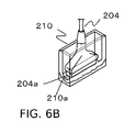
- a probe 204 is accommodated in a holder 210.
- a space is formed such that a holder bottom surface 210a does not interfere with an acoustic lens 204a at the tip of the probe 204 when the probe 204 is accommodated in the holder 210.
- Patent Literature 1 Japanese Patent Application Laid-open No. H7-327996
- Non Patent Literature 1 S.A. Ermilov et al., in “Development of laser optoacoustic and ultrasonic imaging system for breast cancer utilizing handheld array probes", Photons Plus Ultrasound: Imaging and Sensing 2009, Proc. of SPIE vol. 7177, 2009
- H7-327996 is applied to the abovementioned "Development of laser optoacoustic and ultrasonic imaging system for breast cancer utilizing handheld array probes", and the photoacoustic probe 104 is accommodated in the holder, when the illumination light is emitted while the photoacoustic probe 104 is accommodated, the light is reflected and scattered in the holder 210, and is released into the air.
- the holder 210 is formed of a relatively elastic material such as silicone rubber or urethane foam.
- the holder 210 is deformed by the weight of the photoacoustic probe 104, and the gap between the photoacoustic probe 104 and the holder 210 is increased in size.
- the illumination light becomes more likely to be released into the air. Consequently, even when the technique of Japanese Patent Application Laid-open No. H7-327996 is applied to the abovementioned "Development of laser optoacoustic and ultrasonic imaging system for breast cancer utilizing handheld array probes", there has been room for improvement.
- the present invention has been achieved in view of the above problems.
- This invention is developed to prevent the light irradiation from the gap between the photoacoustic probe and the cover.
- the present invention in its first aspect provides an object information acquiring apparatus as specified in claim 1 and 2.
- the present invention in its second aspect provides a cover for photoacoustic probe as specified in claim 3.
- the present invention in its third aspect provides an object information acquiring apparatus as specified in claims 4 to 7.
- the present invention in its fourth aspect provides an object information acquiring apparatus as specified in claims 8 to 16.
- An object information acquiring apparatus of the present invention includes an apparatus that utilizes a photoacoustic effect of receiving an acoustic wave generated inside an object by emitting light (an electromagnetic wave) to the object and acquiring object information as image data.
- the object information includes a source distribution of the acoustic wave generated by light irradiation, an initial sound pressure distribution inside the object, a light energy absorption density distribution or absorption coefficient distribution derived from the initial sound pressure distribution, and a concentration distribution of a substance constituting a tissue. Examples of the concentration distribution of the substance include an oxygen saturation distribution, an oxidized/reduced hemoglobin concentration distribution, and the like.
- a photoacoustic apparatus will be described as an example of the object information acquiring apparatus.
- the acoustic wave mentioned in the present invention is typically an ultrasonic wave, and includes an elastic wave called a sound wave, the ultrasonic wave, or the acoustic wave.
- the acoustic wave generated by the photoacoustic effect is referred to as a photoacoustic wave or a photo-ultrasonic wave.
- FIG. 1 schematically shows the photoacoustic apparatus.
- illumination light L emitted from a light source 1 is shaped by a first illumination optical system 2, and enters into an incident end 3a of a bundle fiber 3.
- the illumination light L is transmitted to a photoacoustic probe 4 by the bundle fiber 3, and is emitted from emission ends 3b of the bundle fiber 3.
- the photoacoustic probe 4 includes the emission ends 3b, second illumination optical systems 5 that shape the illumination light emitted from the emission ends 3b, and a reception section 6 that receives the photoacoustic wave.
- a photoacoustic wave 22 is generated.
- the reception section 6 includes an element for converting the acoustic wave to an electrical signal such as a piezoelectric element or a CMUT. Accordingly, when the reception section 6 receives the photoacoustic wave 22 propagated in the object 20, the photoacoustic wave 22 is converted to an electrical signal (SIG) by the element. Thereafter, the electrical signal (SIG) having been sent to a processor 7 is subjected to amplification, digital conversion, and filtering, and then subjected to image reconstruction by a known method, whereby image information (IMG) is generated. The image information (IMG) is sent to a display device 8, and the information on the inside of the object is displayed.
- an electrical signal such as a piezoelectric element or a CMUT. Accordingly, when the reception section 6 receives the photoacoustic wave 22 propagated in the object 20, the photoacoustic wave 22 is converted to an electrical signal (SIG) by the element. Thereafter, the electrical signal (SIG) having been sent to a processor 7
- the bundle fiber 3 branches at some midpoint to provide the emission end 3b and the second illumination optical system 5 at two locations
- the number of emission ends 3b or second illumination optical systems 5 is not limited thereto.
- it is also effective to provide the emission end 3b and the second illumination optical system 5 adjacent to only one surface of the reception section 6 without the branching, or the number thereof may be three or more.
- covering the photoacoustic probe 4 with a housing has preferable effects such as facilitating usage and enhancing stability.
- the light source 1 emits a near infrared ray preferably having a wavelength of about 600 nm to about 1100 nm.
- the light source 1 it is possible to use, e.g., pulse lasers such as a Nd:YAG laser and an alexandrite laser, a Ti:sa laser using Nd:YAG laser light as excitation light, an OPO laser, and a semiconductor laser.
- the light transmission method is not limited thereto.
- the light transmission method it is also effective to combine mirrors or prisms and use the reflection or refraction thereof. Further, it is also effective to use the semiconductor laser in the light source 1 and replace the emission end 3b with the light source 1.
- the irradiation of the illumination light and the reception of the photoacoustic wave by the reception section 6 need to be synchronized. Accordingly, a part of the optical path between the light source 1 and the second illumination optical system 5 may be caused to branch, light may be detected by a sensor such as a photodiode or the like, and the reception section 6 may be caused to start the reception by using its detection signal as a trigger.
- the light emission timing of the light source 1 and the reception timing of the processor 7 may be synchronized by using a pulse generator that is not shown.
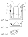
- FIG. 2A is a cross-sectional view showing the photoacoustic probe 4 and a cover 10.
- the cover 10 in FIG. 2A is formed so as to cover the entire photoacoustic probe 4.
- the entire second illumination optical systems 5 are positioned in the cover 10, and a space closer to the entrance of the cover 10 than the second illumination optical system 5 is filled with a light-shielding member 11.
- the entire photoacoustic probe 4 is fixed, a gap becomes less likely to be formed by external forces.
- the cover 10 in FIG. 2B is formed so as to cover at least the tip of the photoacoustic probe 4, i.e., the emission surface of the illumination light. Even with such a shape, it is possible to obtain the sufficient effect of preventing the light irradiation to the outside with the presence of the light-shielding member 11.
- the cover 10 a material having relatively high rigidity such as a metal, a resin such as a plastic, or ceramic, so that no great deformation is induced when the insertion of the photoacoustic probe 4 is implemented.
- the light-shielding member 11 is provided at least in a part of the inner wall of the cover 10. As shown in the perspective view of FIG. 2C , the light-shielding member 11 is preferably formed into a shape that surrounds the photoacoustic probe 4.
- the light-shielding member 11 is preferably formed of a deformable body as a deformable member such as rubber or hard sponge. By forming the light-shielding member 11 by using the deformable body, the gap between a part of a housing 9 as the outer periphery of the photoacoustic probe 4 and the inner wall of the cover 10 is filled by the deformation, and the light leaking to the outside is thereby reduced.
- the tip of the photoacoustic probe including the emission end of the illumination light is covered with the cover, and the gap between the inner wall of the cover and the photoacoustic probe is filled by the deformation of the light-shielding member.
- the light source 1 and the illumination light L in FIG. 3 are the same as those in FIG. 1 .
- the first illumination optical system 2 has a shutter 12, and blocks the light by closing the shutter 12 in response to a shutter close instruction (CLOSE) from a controller 13 as described later.
- CLOSE shutter close instruction
- the photoacoustic probe 4 in FIG. 3 is considered to be substantially the same as that of FIG. 2 though the details thereof are omitted, and has a probe detection sensor 14 inside the cover 10.
- the probe detection sensor 14 inside the cover 10 is provided in order to detect whether or not the tip of the photoacoustic probe 4 including the emission end of the illumination light is covered with the cover 10.
- the probe detection sensor 14 may be a mechanical sensor such as a limit switch, or an optical sensor or an electrostatic sensor can be used as the probe detection sensor 14.
- the probe detection sensor 14 sends probe cover information 31 indicative of whether or not the tip of the photoacoustic probe 4 including the emission end of the illumination light is covered with the cover 10 to the controller 13.
- the controller 13 controls the opening/closing operations of the shutter 12 according to the probe cover information. That is, in a case where the probe cover information indicates that the tip of the photoacoustic probe 4 including the emission end of the illumination light is covered with the cover 10, the controller 13 closes the shutter 12. With this operation, even when the illumination light is emitted from the light source 1, the illumination light is not emitted from the emission end of the illumination light of the photoacoustic probe 4. Accordingly, it is possible to prevent the light irradiation from the emission end when the tip of the photoacoustic probe 4 including the emission end of the illumination light is covered with the cover 10, and hence the safety is improved.
- the light-shielding member 11 is provided inside the cover 10.
- the light is not emitted when the photoacoustic probe 4 is accommodated, and hence it is possible to improve the safety even without the light-shielding member 11.
- the light shielding by the light-shielding member 11 is incomplete. That is, there is a possibility that a gap is formed in a part of the light-shielding member 11 due to the state of molding or the individual difference of the cover 10.
- the light-shielding effect can be reduced due to a reduction in flexibility resulting from the age deterioration of the light-shielding member 11 as the deformable body, or deformation or exfoliation caused by the contact with the photoacoustic probe 4. Even in such cases, by controlling the shutter 12 to suspend the light irradiation itself, it is possible to prevent even more the light leakage and enhance the safety.
- the position of the shutter 12 is not limited thereto, and the shutter 12 may be provided inside the light source 1 or at any position between the light source 1 and the second illumination optical system 5 (not shown in FIG. 3 ).
- the controller 13 can use various methods in order to disable or enable the light irradiation.
- the light irradiation may be controlled by the control by the Q-switch of the light source 1 or by the control of the passage of electric current to the light source 1.
- the light source 1 and the illumination light L in FIG. 4A are the same as those in FIG. 1 .
- the first illumination optical system 2 has the shutter 12, and blocks the light by closing the shutter 12 in response to the shutter close instruction (CLOSE) from the controller 13 as described later.
- CLOSE shutter close instruction
- the photoacoustic probe 4 in FIG. 4A is considered to be substantially the same as that of FIG. 2 though the details thereof are omitted, and a contact detection sensor 15 described later is provided at the tip of the photoacoustic probe 4.
- the contact detection sensor 15 provided in the photoacoustic probe 4 detects whether or not the tip of the photoacoustic probe 4 is in contact with the object 20.
- the contact detection sensor 15 sends contact state information 41 indicative of the contact state between the photoacoustic probe 4 and the object 20.
- the contact state information 41 includes non-contact information indicative of a state in which the photoacoustic probe 4 and the object 20 are not in contact with each other and contact information indicative of a state in which the photoacoustic probe 4 and the object 20 are in contact with each other.
- the controller 13 controls the opening/closing operations of the shutter 12 according to the contact state information 41. That is, in a case where the non-contact information is received as the contact state information 41, the controller 13 closes the shutter 12 to prevent the irradiation from the tip of the photoacoustic probe 4. Conversely, in a case where the contact information is received as the contact state information 41, the controller 13 opens the shutter 12 to allow the illumination light emitted from the light source 1 to be emitted from the tip of the photoacoustic probe 4.
- the contact detection sensor 15 may not be in contact with the bottom surface 10a of the cover 10 appropriately so that it is only necessary to provide the gap 23 such that they don't interfere with each other.
- the gap 23 that sufficiently reduces its capacity is provided.
- the gap 23 is provided such that light that returns after being reflected by its light reception section becomes sufficiently reduced.
- the light of the optical sensor may be prevented from returning to the light reception section by tilting the bottom surface 10a of the cover 10.
- the light of the optical sensor may be prevented from returning to the light reception section by frosting the bottom surface 10a of the cover 10 using deep colors by painting or plating, or by sandblasting the surface.
- the controller 13 closes the shutter 12.
- the shutter opening control is performed based on the contact information so that it is possible to perform the light irradiation with no problem.
- the position of the shutter 12 is not limited thereto, and the shutter 12 may be provided inside the light source 1 or at any position between the light source 1 and the second illumination optical system 5 (not shown in FIG. 4 ).
- the light may be controlled by the control by the Q-switch of the light source 1 or the control of the passage of electric current to the light source 1.
- the contact detection sensor 15 can break down due to the short circuit of wiring or a substrate, and hence it is preferable to perform a fault diagnosis periodically, when the apparatus is started, or before the object is measured.
- the flowchart of FIG. 4B shows the process of the fault diagnosis.
- the controller 13 starts the fault diagnosis of the contact detection sensor 15 in the state in which the tip of the photoacoustic probe 4 is covered with the cover 10.
- Step S41 the controller 13 confirms whether or not the contact detection sensor 15 outputs the non-contact information.
- the process advances to Step S42, and the fault diagnosis process is normally ended.
- the process advances to Step S43, the fault diagnosis process is abnormally ended, and an alarm about the fault of the contact detection sensor 15 is issued.
- control of the light irradiation of the photoacoustic probe 4 in particular, an example of a determination method of the fault of the probe will be described with reference to FIGS. 5A and 5B .
- the contact detection sensor 15 determines the contact state between the photoacoustic probe 4 and the cover 10 and outputs the contact state information 41, and the controller 13 performs the fault diagnosis based on whether or not the non-contact information is outputted as the contact state information 41.
- the fault diagnosis is performed further by using the contact information of the contact state information 41.
- the photoacoustic probe 4 in FIG. 5A is considered to be substantially the same as that of FIG. 2 though the details thereof are omitted, the probe detection sensor 14 is provided inside the cover 10, and the contact detection sensor 15 is provided at the tip of the photoacoustic probe 4.
- a movable section 16 is provided on the bottom surface 10a of the cover 10.
- the movable section 16 is provided at a position that opposes the contact detection sensor 15 when the photoacoustic probe 4 is inserted into the cover 10.
- the movable range of the movable section 16 lies between the position close to the contact detection sensor 15 that causes the contact detection sensor 15 to output the contact information and the position away from the contact detection sensor 15 that causes the contact detection sensor 15 to output the non-contact information.
- the fault diagnosis in the present embodiment is performed according to the flowchart of FIG. 5B , and the fault diagnosis of the contact detection sensor 15 is performed by the controller 13 in the state in which the tip of the photoacoustic probe 4 is covered with the cover 10.
- Step S51 the movable section 16 is moved to the position that causes the contact detection sensor 15 to output the non-contact information as the contact state information.
- the position of the movable section 16 is transmitted to the controller 13 as position information 51.
- Step S52 the controller 13 confirms whether or not the contact detection sensor 15 outputs the non-contact information.
- the process advances to Step S56, the fault diagnosis is abnormally ended, and the alarm about the fault of the contact detection sensor 15 is outputted.
- Step S54 the controller 13 confirms whether or not the contact detection sensor 15 outputs the contact information.
- the process advances to Step S56, the fault diagnosis is abnormally ended, and the alarm about the fault of the contact detection sensor 15 is outputted.
- the contact detection sensor 15 since the contact detection sensor 15 outputs the contact information in the state of each of S53 and S54, the state in which the irradiation of the illumination light is allowed is established.
- the probe detection sensor 14 is provided inside the cover 10.
- the controller 13 closes the shutter 12 (not shown in FIG. 5A ).
- an object information acquiring apparatus that has a light source; a photoacoustic probe including an emission end that emits light from the light source to an object and a reception section that receives an acoustic wave generated from the object to which the light is emitted; a cover covering at least the emission end of the photoacoustic probe; a light-shielding member provided inside the cover and filling a gap formed between the photoacoustic probe and the cover when the photoacoustic probe is inserted into the cover; and a processor acquiring information on the inside of the object based on the acoustic wave.
Landscapes
- Health & Medical Sciences (AREA)
- Life Sciences & Earth Sciences (AREA)
- Physics & Mathematics (AREA)
- Pathology (AREA)
- General Health & Medical Sciences (AREA)
- Engineering & Computer Science (AREA)
- Veterinary Medicine (AREA)
- Biomedical Technology (AREA)
- Heart & Thoracic Surgery (AREA)
- Medical Informatics (AREA)
- Molecular Biology (AREA)
- Surgery (AREA)
- Animal Behavior & Ethology (AREA)
- Biophysics (AREA)
- Public Health (AREA)
- Optics & Photonics (AREA)
- Acoustics & Sound (AREA)
- Immunology (AREA)
- Chemical & Material Sciences (AREA)
- Analytical Chemistry (AREA)
- Biochemistry (AREA)
- General Physics & Mathematics (AREA)
- Nuclear Medicine, Radiotherapy & Molecular Imaging (AREA)
- Radiology & Medical Imaging (AREA)
- Ultra Sonic Daignosis Equipment (AREA)
- Investigating Or Analyzing Materials By The Use Of Ultrasonic Waves (AREA)
- Psychiatry (AREA)
- Computer Vision & Pattern Recognition (AREA)
- Physiology (AREA)
- Artificial Intelligence (AREA)
- Signal Processing (AREA)
Abstract


Description
- The present invention relates to an object information acquiring apparatus and a cover for a photoacoustic probe.
- As a method for specifically imaging vascularization resulting from a cancer, attention is paid to photoacoustic tomography (hereinafter referred to as PAT). The PAT is a method in which illumination light (near infrared rays) is emitted to an object, a photoacoustic wave emitted from the inside of the object is received by an ultrasonic probe, and the received photoacoustic wave is imaged.
-
FIG. 6A is a schematic diagram of a handheld photoacoustic apparatus described in technique by S.A. Ermilov et al., in "Development of laser optoacoustic and ultrasonic imaging system for breast cancer utilizing handheld array probes", Photons Plus Ultrasound: Imaging and Sensing 2009, Proc. of SPIE vol. 7177, 2009. Aphotoacoustic probe 104 has a structure in which areception section 106 for receiving the photoacoustic wave is sandwiched by illumination optical systems includingemission ends 103b ofbundle fibers 103. Illumination light from alight source 101 enters into thebundle fibers 103 from anincident end 103a, and is emitted to the object from theemission ends 103b. Subsequently, the photoacoustic wave generated from the object by a photoacoustic effect is received by thereception section 106, and is converted to an electrical signal. Aprocessor 107 of anultrasonic device 109 performs amplification, digitization, and image reconstruction on the electrical signal to thereby generate image information (IMG), and transmits the image information to adisplay device 108. With this, a photoacoustic image indicative of characteristic information on the inside of the object is displayed. - In the abovementioned "Development of laser optoacoustic and ultrasonic imaging system for breast cancer utilizing handheld array probes", in a case where the illumination light is emitted when the photoacoustic probe is not used (e.g., when the photoacoustic probe is not in contact with the object), the illumination light having a relatively high energy density is released into the air. Consequently, when the photoacoustic probe is not used, it is preferable to cover at least the emission end of the photoacoustic probe.
- Next, in Japanese Patent Application Laid-open No.
H7-327996 FIG. 6B , an ultrasonic probe can be accommodated. InFIG. 6B , aprobe 204 is accommodated in aholder 210. A space is formed such that aholder bottom surface 210a does not interfere with anacoustic lens 204a at the tip of theprobe 204 when theprobe 204 is accommodated in theholder 210. - Patent Literature 1: Japanese Patent Application Laid-open No.
H7-327996 - Non Patent Literature 1: S.A. Ermilov et al., in "Development of laser optoacoustic and ultrasonic imaging system for breast cancer utilizing handheld array probes", Photons Plus Ultrasound: Imaging and Sensing 2009, Proc. of SPIE vol. 7177, 2009
- However, the conventional art has had the following problems.
The use of the folder (cover) in Japanese Patent Application Laid-open No.H7-327996 H7-327996 holder 210 and theprobe 204 when theprobe 204 is accommodated in theholder 210. Consequently, in a case where theholder 210 of Japanese Patent Application Laid-open No.H7-327996 photoacoustic probe 104 is accommodated in the holder, when the illumination light is emitted while thephotoacoustic probe 104 is accommodated, the light is reflected and scattered in theholder 210, and is released into the air. - In addition, in Japanese Patent Application Laid-open No.
H7-327996 holder 210 is formed of a relatively elastic material such as silicone rubber or urethane foam. However, in this case, when thephotoacoustic probe 104 is accommodated in theholder 210, theholder 210 is deformed by the weight of thephotoacoustic probe 104, and the gap between thephotoacoustic probe 104 and theholder 210 is increased in size. As a result, the illumination light becomes more likely to be released into the air. Consequently, even when the technique of Japanese Patent Application Laid-open No.H7-327996 - The present invention has been achieved in view of the above problems. This invention is developed to prevent the light irradiation from the gap between the photoacoustic probe and the cover.
- The present invention in its first aspect provides an object information acquiring apparatus as specified in
claim - The present invention in its second aspect provides a cover for photoacoustic probe as specified in
claim 3. - The present invention in its third aspect provides an object information acquiring apparatus as specified in
claims 4 to 7. - The present invention in its fourth aspect provides an object information acquiring apparatus as specified in
claims 8 to 16. - According to the present invention, it is possible to prevent the light irradiation from the gap between the photoacoustic probe and the cover.
Further features of the present invention will become apparent from the following description of exemplary embodiments with reference to the attached drawings. -
-
FIG. 1 is a view for explaining the configuration of a photoacoustic apparatus in an embodiment of the present invention; -
FIGS. 2A to 2C are views for explaining a cover of a photoacoustic probe in the embodiment of the present invention; -
FIG. 3 is a view for explaining the cover of the photoacoustic probe in a first embodiment; -
FIGS. 4A and 4B are views for explaining the cover of the photoacoustic probe in a second embodiment; -
FIG. 5A is a view for explaining the photoacoustic probe in a third embodiment; -
FIG. 5B is a flowchart for explaining a fault diagnosis process in the third embodiment; -
FIG. 6A is a view for explaining the configuration of the photoacoustic device of the background art; and -
FIG. 6B is a view for explaining the configuration of each of a probe and a holder of the background art. - Hereinbelow, preferred embodiments of the present invention will be described with reference to the drawings. However, the dimension, material, shape, and relative arrangement of each component described below should be appropriately changed according to the configuration and various conditions of an apparatus to which the invention is applied, and are not intended to limit the scope of the invention to the following description.
- An object information acquiring apparatus of the present invention includes an apparatus that utilizes a photoacoustic effect of receiving an acoustic wave generated inside an object by emitting light (an electromagnetic wave) to the object and acquiring object information as image data. The object information includes a source distribution of the acoustic wave generated by light irradiation, an initial sound pressure distribution inside the object, a light energy absorption density distribution or absorption coefficient distribution derived from the initial sound pressure distribution, and a concentration distribution of a substance constituting a tissue. Examples of the concentration distribution of the substance include an oxygen saturation distribution, an oxidized/reduced hemoglobin concentration distribution, and the like.
In the following description, a photoacoustic apparatus will be described as an example of the object information acquiring apparatus. - The acoustic wave mentioned in the present invention is typically an ultrasonic wave, and includes an elastic wave called a sound wave, the ultrasonic wave, or the acoustic wave. The acoustic wave generated by the photoacoustic effect is referred to as a photoacoustic wave or a photo-ultrasonic wave.
- An embodiment of the present invention will be described by using
FIGS. 1 and2 .FIG. 1 schematically shows the photoacoustic apparatus. In the photoacoustic apparatus, illumination light L emitted from alight source 1 is shaped by a first illuminationoptical system 2, and enters into anincident end 3a of abundle fiber 3. The illumination light L is transmitted to aphotoacoustic probe 4 by thebundle fiber 3, and is emitted from emission ends 3b of thebundle fiber 3. - The
photoacoustic probe 4 includes the emission ends 3b, second illuminationoptical systems 5 that shape the illumination light emitted from the emission ends 3b, and areception section 6 that receives the photoacoustic wave. When the illumination light having reached anobject 20 via the second illuminationoptical systems 5 is diffused and propagated inside the object, and is absorbed by anabsorbent body 21, a photoacoustic wave 22 is generated. - The
reception section 6 includes an element for converting the acoustic wave to an electrical signal such as a piezoelectric element or a CMUT. Accordingly, when thereception section 6 receives the photoacoustic wave 22 propagated in theobject 20, the photoacoustic wave 22 is converted to an electrical signal (SIG) by the element. Thereafter, the electrical signal (SIG) having been sent to aprocessor 7 is subjected to amplification, digital conversion, and filtering, and then subjected to image reconstruction by a known method, whereby image information (IMG) is generated. The image information (IMG) is sent to adisplay device 8, and the information on the inside of the object is displayed. - Note that, in
FIG. 1 , although thebundle fiber 3 branches at some midpoint to provide theemission end 3b and the second illuminationoptical system 5 at two locations, the number of emission ends 3b or second illuminationoptical systems 5 is not limited thereto. For example, it is also effective to provide theemission end 3b and the second illuminationoptical system 5 adjacent to only one surface of thereception section 6 without the branching, or the number thereof may be three or more.
In addition, although not shown in the drawing, covering thephotoacoustic probe 4 with a housing has preferable effects such as facilitating usage and enhancing stability. - The
light source 1 emits a near infrared ray preferably having a wavelength of about 600 nm to about 1100 nm. As thelight source 1, it is possible to use, e.g., pulse lasers such as a Nd:YAG laser and an alexandrite laser, a Ti:sa laser using Nd:YAG laser light as excitation light, an OPO laser, and a semiconductor laser. - In
FIG. 1 , although the illumination light emitted by thelight source 1 is transmitted to the emission ends 3b via the first illuminationoptical system 2 and thebundle fiber 3, the light transmission method is not limited thereto. As the light transmission method, it is also effective to combine mirrors or prisms and use the reflection or refraction thereof. Further, it is also effective to use the semiconductor laser in thelight source 1 and replace theemission end 3b with thelight source 1. - Note that the irradiation of the illumination light and the reception of the photoacoustic wave by the
reception section 6 need to be synchronized. Accordingly, a part of the optical path between thelight source 1 and the second illuminationoptical system 5 may be caused to branch, light may be detected by a sensor such as a photodiode or the like, and thereception section 6 may be caused to start the reception by using its detection signal as a trigger. In addition, the light emission timing of thelight source 1 and the reception timing of theprocessor 7 may be synchronized by using a pulse generator that is not shown. -
FIG. 2A is a cross-sectional view showing thephotoacoustic probe 4 and acover 10. Thecover 10 inFIG. 2A is formed so as to cover the entirephotoacoustic probe 4. As shown in the drawing, the entire second illuminationoptical systems 5 are positioned in thecover 10, and a space closer to the entrance of thecover 10 than the second illuminationoptical system 5 is filled with a light-shieldingmember 11. As a result, even when the light is emitted in a state in which thephotoacoustic probe 4 is accommodated, the light does not leak to the outside of thecover 10. Further, the entirephotoacoustic probe 4 is fixed, a gap becomes less likely to be formed by external forces. - On the other hand, the
cover 10 inFIG. 2B is formed so as to cover at least the tip of thephotoacoustic probe 4, i.e., the emission surface of the illumination light. Even with such a shape, it is possible to obtain the sufficient effect of preventing the light irradiation to the outside with the presence of the light-shieldingmember 11. - Note that, in each of
FIGS. 2A and 2B , although the end of thephotoacoustic probe 4 is oriented downward and the tip thereof is covered with thecover 10, the orientation is not limited to the downward orientation, and is arbitrarily determined. - It is preferable to use, for the
cover 10, a material having relatively high rigidity such as a metal, a resin such as a plastic, or ceramic, so that no great deformation is induced when the insertion of thephotoacoustic probe 4 is implemented. - The light-shielding
member 11 is provided at least in a part of the inner wall of thecover 10. As shown in the perspective view ofFIG. 2C , the light-shieldingmember 11 is preferably formed into a shape that surrounds thephotoacoustic probe 4. The light-shieldingmember 11 is preferably formed of a deformable body as a deformable member such as rubber or hard sponge. By forming the light-shieldingmember 11 by using the deformable body, the gap between a part of ahousing 9 as the outer periphery of thephotoacoustic probe 4 and the inner wall of thecover 10 is filled by the deformation, and the light leaking to the outside is thereby reduced. - According to the configuration described above, it becomes possible to prevent the deformation of the
cover 10 for the photoacoustic probe and reduce the gap between thecover 10 and thephotoacoustic probe 4 by the deformation of the light-shieldingmember 11. As a result, by covering the tip of thephotoacoustic probe 4 with thecover 10 when the measurement is not performed, it is possible to significantly reduce the light leaking to the outside even when the illumination light is emitted. - That is, the tip of the photoacoustic probe including the emission end of the illumination light is covered with the cover, and the gap between the inner wall of the cover and the photoacoustic probe is filled by the deformation of the light-shielding member. As a result, only by covering the photoacoustic probe with the cover, even when the illumination light is emitted, it becomes possible to significantly reduce the light leaking to the outside, and improve safety regarding the illumination light.
- In the present embodiment, an example of the control of the light irradiation of the
photoacoustic probe 4 will be described with reference toFIG. 3 . - The
light source 1 and the illumination light L inFIG. 3 are the same as those inFIG. 1 . The first illuminationoptical system 2 has ashutter 12, and blocks the light by closing theshutter 12 in response to a shutter close instruction (CLOSE) from acontroller 13 as described later. Thephotoacoustic probe 4 inFIG. 3 is considered to be substantially the same as that ofFIG. 2 though the details thereof are omitted, and has aprobe detection sensor 14 inside thecover 10. - The
probe detection sensor 14 inside thecover 10 is provided in order to detect whether or not the tip of thephotoacoustic probe 4 including the emission end of the illumination light is covered with thecover 10. Theprobe detection sensor 14 may be a mechanical sensor such as a limit switch, or an optical sensor or an electrostatic sensor can be used as theprobe detection sensor 14. Theprobe detection sensor 14 sendsprobe cover information 31 indicative of whether or not the tip of thephotoacoustic probe 4 including the emission end of the illumination light is covered with thecover 10 to thecontroller 13. - The
controller 13 controls the opening/closing operations of theshutter 12 according to the probe cover information. That is, in a case where the probe cover information indicates that the tip of thephotoacoustic probe 4 including the emission end of the illumination light is covered with thecover 10, thecontroller 13 closes theshutter 12. With this operation, even when the illumination light is emitted from thelight source 1, the illumination light is not emitted from the emission end of the illumination light of thephotoacoustic probe 4. Accordingly, it is possible to prevent the light irradiation from the emission end when the tip of thephotoacoustic probe 4 including the emission end of the illumination light is covered with thecover 10, and hence the safety is improved. - In
FIG. 3 , the light-shieldingmember 11 is provided inside thecover 10. However, according to the method of the present embodiment, the light is not emitted when thephotoacoustic probe 4 is accommodated, and hence it is possible to improve the safety even without the light-shieldingmember 11. - It goes without saying that, even in a case where the
cover 10 includes the light-shieldingmember 11, it is possible to enhance the effect by the combination of light shielding by the light-shielding member and the suspension of the light irradiation using theprobe detection sensor 14. - Further, there can be considered a case where the light shielding by the light-shielding
member 11 is incomplete. That is, there is a possibility that a gap is formed in a part of the light-shieldingmember 11 due to the state of molding or the individual difference of thecover 10. In addition, the light-shielding effect can be reduced due to a reduction in flexibility resulting from the age deterioration of the light-shieldingmember 11 as the deformable body, or deformation or exfoliation caused by the contact with thephotoacoustic probe 4. Even in such cases, by controlling theshutter 12 to suspend the light irradiation itself, it is possible to prevent even more the light leakage and enhance the safety. - Although the
shutter 12 is provided inside the first illuminationoptical system 2, the position of theshutter 12 is not limited thereto, and theshutter 12 may be provided inside thelight source 1 or at any position between thelight source 1 and the second illumination optical system 5 (not shown inFIG. 3 ).
In addition, thecontroller 13 can use various methods in order to disable or enable the light irradiation. For example, instead of using theshutter 12, the light irradiation may be controlled by the control by the Q-switch of thelight source 1 or by the control of the passage of electric current to thelight source 1. - In the present embodiment, an example of the control of the light irradiation of the
photoacoustic probe 4 will be described with reference toFIG. 4 . - The
light source 1 and the illumination light L inFIG. 4A are the same as those inFIG. 1 . In addition, the first illuminationoptical system 2 has theshutter 12, and blocks the light by closing theshutter 12 in response to the shutter close instruction (CLOSE) from thecontroller 13 as described later. Thephotoacoustic probe 4 inFIG. 4A is considered to be substantially the same as that ofFIG. 2 though the details thereof are omitted, and acontact detection sensor 15 described later is provided at the tip of thephotoacoustic probe 4. - The
contact detection sensor 15 provided in thephotoacoustic probe 4 detects whether or not the tip of thephotoacoustic probe 4 is in contact with theobject 20. Thecontact detection sensor 15 sendscontact state information 41 indicative of the contact state between thephotoacoustic probe 4 and theobject 20. Thecontact state information 41 includes non-contact information indicative of a state in which thephotoacoustic probe 4 and theobject 20 are not in contact with each other and contact information indicative of a state in which thephotoacoustic probe 4 and theobject 20 are in contact with each other. - The
controller 13 controls the opening/closing operations of theshutter 12 according to thecontact state information 41. That is, in a case where the non-contact information is received as thecontact state information 41, thecontroller 13 closes theshutter 12 to prevent the irradiation from the tip of thephotoacoustic probe 4. Conversely, in a case where the contact information is received as thecontact state information 41, thecontroller 13 opens theshutter 12 to allow the illumination light emitted from thelight source 1 to be emitted from the tip of thephotoacoustic probe 4. - At this point, when the distance between the
contact detection sensor 15 and abottom surface 10a of thecover 10 is short, the possibility is increased that thecontact detection sensor 15 erroneously detects that thephotoacoustic probe 4 and theobject 20 are in contact with each other. Consequently, it is necessary to form asufficient gap 23 between thecontact detection sensor 15 and thebottom surface 10a of thecover 10. - In a case where the mechanical sensor such as the limit switch or a strain gauge is used as the
contact detection sensor 15, thecontact detection sensor 15 may not be in contact with thebottom surface 10a of thecover 10 appropriately so that it is only necessary to provide thegap 23 such that they don't interfere with each other.
In addition, in a case where a capacitive sensor is used as thecontact detection sensor 15, thegap 23 that sufficiently reduces its capacity is provided. - Further, in a case where the optical sensor is used as the
contact detection sensor 15, thegap 23 is provided such that light that returns after being reflected by its light reception section becomes sufficiently reduced. Alternatively, the light of the optical sensor may be prevented from returning to the light reception section by tilting thebottom surface 10a of thecover 10. Similarly, the light of the optical sensor may be prevented from returning to the light reception section by frosting thebottom surface 10a of thecover 10 using deep colors by painting or plating, or by sandblasting the surface. - According to the configuration described above, since the
contact detection sensor 15 sends the non-contact information to thecontroller 13 when the tip of thephotoacoustic probe 4 is covered with thecover 10, thecontroller 13 closes theshutter 12. As a result, since it is possible to prevent the irradiation from the emission end when the tip of thephotoacoustic probe 4 including the emission end of the illumination light is covered with thecover 10, the safety is improved.
On the other hand, in a case where thephotoacoustic probe 4 is pushed against the object to perform the photoacoustic measurement, the shutter opening control is performed based on the contact information so that it is possible to perform the light irradiation with no problem. - Although the
shutter 12 is provided inside the first illuminationoptical system 2, the position of theshutter 12 is not limited thereto, and theshutter 12 may be provided inside thelight source 1 or at any position between thelight source 1 and the second illumination optical system 5 (not shown inFIG. 4 ). Alternatively, instead of theshutter 12, the light may be controlled by the control by the Q-switch of thelight source 1 or the control of the passage of electric current to thelight source 1. - In addition, the
contact detection sensor 15 can break down due to the short circuit of wiring or a substrate, and hence it is preferable to perform a fault diagnosis periodically, when the apparatus is started, or before the object is measured. - The flowchart of
FIG. 4B shows the process of the fault diagnosis. Thecontroller 13 starts the fault diagnosis of thecontact detection sensor 15 in the state in which the tip of thephotoacoustic probe 4 is covered with thecover 10.
In Step S41, thecontroller 13 confirms whether or not thecontact detection sensor 15 outputs the non-contact information. When thecontact detection sensor 15 outputs the non-contact information (S41 = Y), the process advances to Step S42, and the fault diagnosis process is normally ended. On the other hand, when thecontact detection sensor 15 outputs the contact information (S41 = N), the process advances to Step S43, the fault diagnosis process is abnormally ended, and an alarm about the fault of thecontact detection sensor 15 is issued. - Thus, it is possible to perform the fault diagnosis of the
contact detection sensor 15 in the state in which the tip of thephotoacoustic probe 4 is covered with thecover 10 so that it becomes possible to not only improve the safety but also smoothly perform the inspection before use. - Note that, in the present embodiment as well, similarly to
Embodiment 1, since the light is not emitted when thephotoacoustic probe 4 is accommodated, it is possible to obtain the effect of improving the safety even in the case where the light-shieldingmember 11 is not present. Further, it is possible to enhance the effect by the combination of the installation of the light-shieldingmember 11 and the irradiation suspension control by the controller. - In the present embodiment, the control of the light irradiation of the
photoacoustic probe 4, in particular, an example of a determination method of the fault of the probe will be described with reference toFIGS. 5A and5B . - In
Embodiment 2, thecontact detection sensor 15 determines the contact state between thephotoacoustic probe 4 and thecover 10 and outputs thecontact state information 41, and thecontroller 13 performs the fault diagnosis based on whether or not the non-contact information is outputted as thecontact state information 41. In the present embodiment, the fault diagnosis is performed further by using the contact information of thecontact state information 41. - The
photoacoustic probe 4 inFIG. 5A is considered to be substantially the same as that ofFIG. 2 though the details thereof are omitted, theprobe detection sensor 14 is provided inside thecover 10, and thecontact detection sensor 15 is provided at the tip of thephotoacoustic probe 4. - In addition, in the present embodiment, a
movable section 16 is provided on thebottom surface 10a of thecover 10. Themovable section 16 is provided at a position that opposes thecontact detection sensor 15 when thephotoacoustic probe 4 is inserted into thecover 10. The movable range of themovable section 16 lies between the position close to thecontact detection sensor 15 that causes thecontact detection sensor 15 to output the contact information and the position away from thecontact detection sensor 15 that causes thecontact detection sensor 15 to output the non-contact information. - The fault diagnosis in the present embodiment is performed according to the flowchart of
FIG. 5B , and the fault diagnosis of thecontact detection sensor 15 is performed by thecontroller 13 in the state in which the tip of thephotoacoustic probe 4 is covered with thecover 10. - When the process is started, first, in Step S51, the
movable section 16 is moved to the position that causes thecontact detection sensor 15 to output the non-contact information as the contact state information. The position of themovable section 16 is transmitted to thecontroller 13 asposition information 51.
Next, in Step S52, thecontroller 13 confirms whether or not thecontact detection sensor 15 outputs the non-contact information. In a case where the non-contact information is not outputted (S52 = N), the process advances to Step S56, the fault diagnosis is abnormally ended, and the alarm about the fault of thecontact detection sensor 15 is outputted.
On the other hand, when S52 = Y is satisfied, the process advances to Step S53, and themovable section 16 is moved close to thecontact detection sensor 15 to the position that causes thecontact detection sensor 15 to output the contact information as the contact state information. - Next, in Step S54, the
controller 13 confirms whether or not thecontact detection sensor 15 outputs the contact information. In a case where the contact information is not outputted (S54 = N), the process advances to Step S56, the fault diagnosis is abnormally ended, and the alarm about the fault of thecontact detection sensor 15 is outputted.
On the other hand, when S54 = Y is satisfied, the process advances to Step S55, and the process is normally ended. - Thus, according to the present embodiment, since it is possible to perform the fault diagnosis by using both of the contact information and the non-contact information of the
contact state information 41 in the state in which the tip of thephotoacoustic probe 4 is covered with thecover 10, it is possible to enhance the accuracy of the diagnosis and further improve the safety. - In the fault diagnosis of the
contact detection sensor 15 according to the above-described flowchart, since thecontact detection sensor 15 outputs the contact information in the state of each of S53 and S54, the state in which the irradiation of the illumination light is allowed is established. - To cope with this, in the present embodiment, as shown in
FIG. 5A , theprobe detection sensor 14 is provided inside thecover 10. In a case where information indicating that the tip of thephotoacoustic probe 4 is covered with thecover 10 is outputted as the probe coverinformation 31, thecontroller 13 closes the shutter 12 (not shown inFIG. 5A ). - With this arrangement, even when the contact information is temporarily outputted during the fault diagnosis, when the tip of the
photoacoustic probe 4 is covered with thecover 10, the irradiation from the emission end is prevented. As a result, it is possible to obtain the effects of improving the safety and smoothly performing the inspection before use. - While the present invention has been described with reference to exemplary embodiments, it is to be understood that the invention is not limited to the disclosed exemplary embodiments. The scope of the following claims is to be accorded the broadest interpretation so as to encompass all such modifications and equivalent structures and functions.
There is used an object information acquiring apparatus that has a light source; a photoacoustic probe including an emission end that emits light from the light source to an object and a reception section that receives an acoustic wave generated from the object to which the light is emitted; a cover covering at least the emission end of the photoacoustic probe; a light-shielding member provided inside the cover and filling a gap formed between the photoacoustic probe and the cover when the photoacoustic probe is inserted into the cover; and a processor acquiring information on the inside of the object based on the acoustic wave.
Claims (16)
- An object information acquiring apparatus comprising:a light source;a photoacoustic probe including an emission end that emits light from the light source to an object and a reception section that receives an acoustic wave generated from the object to which the light is emitted;a cover configured to cover at least the emission end of the photoacoustic probe;a light-shielding member provided inside the cover and filling a gap formed between the photoacoustic probe and the cover when the photoacoustic probe is inserted into the cover; anda processor configured to acquire information on an inside of the object based on the acoustic wave.
- The object information acquiring apparatus according to claim 1, wherein the light-shielding member is formed of a deformable body that is deformed into a shape surrounding the photoacoustic probe when the photoacoustic probe is inserted into the cover.
- A cover for a photoacoustic probe including an emission end that emits light from a light source to an object and a reception section that receives an acoustic wave generated from the object to which the light is emitted,
the cover being formed to cover at least the emission end of the photoacoustic probe, and
a light-shielding member that fills a gap formed between the photoacoustic probe and the cover when the photoacoustic probe is inserted into the cover being provided inside the cover. - An object information acquiring apparatus comprising:a light source;a photoacoustic probe including an emission end that emits light from the light source to an object and a reception section that receives an acoustic wave generated from the object to which the light is emitted;a cover configured to cover at least the emission end of the photoacoustic probe;a probe detection sensor provided inside the cover and detecting whether or not the emission end is covered with the cover;a controller configured to control light emission from the light source according to an output from the probe detection sensor; anda processor configured to acquire information on an inside of the object based on the acoustic wave.
- The object information acquiring apparatus according to claim 4, wherein the controller implements control to disable the light emission in a case where the emission end is covered with the cover.
- The object information acquiring apparatus according to claim 4 or 5, wherein the controller controls the light emission by using any of a control of a shutter, a control of a Q-switch, and a control of passage of electric current to the light source.
- The object information acquiring apparatus according to any one of claims 4 to 6, wherein the probe detection sensor is any of a mechanical sensor, an optical sensor, and an electrostatic sensor.
- An object information acquiring apparatus comprising:a light source;a photoacoustic probe including an emission end that emits light from the light source to an object and a reception section that receives an acoustic wave generated from the object to which the light is emitted;a cover configured to cover at least the emission end of the photoacoustic probe;a contact detection sensor provided in the photoacoustic probe and detecting a contact between the photoacoustic probe and the object;a controller configured to control light emission from the light source according to an output of the contact detection sensor; anda processor configured to acquire information on an inside of the object based on the acoustic wave.
- The object information acquiring apparatus according to claim 8, wherein the controller implements control to disable the light emission in a case where non-contact information indicating that the photoacoustic probe and the object are not in contact with each other is outputted from the contact detection sensor.
- The object information acquiring apparatus according to claim 8 or 9, wherein the controller implements control to enable the light emission in a case where contact information indicating that the photoacoustic probe and the object are in contact with each other is outputted from the contact detection sensor.
- The object information acquiring apparatus according to any one of claims 8 to 10, wherein a gap is formed between the contact detection sensor and an inner wall of the cover that the contact detection sensor opposes when the photoacoustic probe is inserted into the cover.
- The object information acquiring apparatus according to any one of claims 8 to 11, wherein the controller performs a fault diagnosis of the contact detection sensor based on the output of the contact detection sensor.
- The object information acquiring apparatus according to any one of claims 8 to 12, wherein the controller determines that the contact detection sensor is not faulty in a case where non-contact information indicating that the photoacoustic probe and the object are not in contact with each other is outputted from the contact detection sensor in a state in which the photoacoustic probe is inserted into the cover.
- The object information acquiring apparatus according to claim 13, wherein
a movable section movable between a position close to the contact detection sensor and a position away from the contact detection sensor is provided at a position on an inner wall of the cover that opposes the contact detection sensor when the photoacoustic probe is inserted into the cover, and
the controller determines that the contact detection sensor is not faulty in a case where contact information indicating that the photoacoustic probe and the object are in contact with each other is outputted from the contact detection sensor in a state in which the photoacoustic probe is inserted into the cover and in which the movable section is at the position close to the contact detection sensor. - The object information acquiring apparatus according to claim 13 or 14, further comprising:a probe detection sensor provided inside the cover and detecting whether or not the emission end is covered with the cover, whereinthe controller controls the light emission from the light source according to an output from the probe detection sensor.
- The object information acquiring apparatus according to any one of claims 8 to 15, wherein the contact detection sensor is any of a mechanical sensor, an optical sensor, and an electrostatic sensor.
Applications Claiming Priority (1)
| Application Number | Priority Date | Filing Date | Title |
|---|---|---|---|
| JP2012233900A JP2014083195A (en) | 2012-10-23 | 2012-10-23 | Subject information acquisition apparatus and cover for photoacoustic probe |
Publications (2)
| Publication Number | Publication Date |
|---|---|
| EP2724665A2 true EP2724665A2 (en) | 2014-04-30 |
| EP2724665A3 EP2724665A3 (en) | 2014-06-18 |
Family
ID=49253081
Family Applications (1)
| Application Number | Title | Priority Date | Filing Date |
|---|---|---|---|
| EP13184315.3A Withdrawn EP2724665A3 (en) | 2012-10-23 | 2013-09-13 | Object information acquiring apparatus and cover for photoacoustic probe |
Country Status (4)
| Country | Link |
|---|---|
| US (1) | US20140114170A1 (en) |
| EP (1) | EP2724665A3 (en) |
| JP (1) | JP2014083195A (en) |
| CN (2) | CN105193444B (en) |
Families Citing this family (7)
| Publication number | Priority date | Publication date | Assignee | Title |
|---|---|---|---|---|
| JP5863345B2 (en) * | 2011-09-08 | 2016-02-16 | キヤノン株式会社 | Subject information acquisition apparatus and subject information acquisition method |
| JP6172912B2 (en) | 2012-10-23 | 2017-08-02 | キヤノン株式会社 | Subject information acquisition apparatus and photoacoustic probe |
| JP6351227B2 (en) | 2013-09-30 | 2018-07-04 | キヤノン株式会社 | Subject information acquisition device |
| JP6049209B2 (en) * | 2014-01-28 | 2016-12-21 | 富士フイルム株式会社 | Photoacoustic measurement probe and photoacoustic measurement apparatus including the same |
| JP6262679B2 (en) * | 2015-02-26 | 2018-01-17 | 富士フイルム株式会社 | Photoacoustic measuring device |
| WO2022266250A1 (en) * | 2021-06-16 | 2022-12-22 | The Board Of Regents Of The University Of Texas System | Sequential adaptor for combined ultrasound and optoacoustic diagnostic interrogation of the left innominate vein |
| EP4365575B1 (en) * | 2022-11-02 | 2025-07-02 | Eclypia | Photoacoustic detecting device comprising a housing kit |
Citations (3)
| Publication number | Priority date | Publication date | Assignee | Title |
|---|---|---|---|---|
| US5050436A (en) * | 1989-02-14 | 1991-09-24 | Kabushiki Kaisha Toshiba | Ultrasonic probe and acoustic lens attachment |
| JPH07327996A (en) | 1994-06-15 | 1995-12-19 | Ge Yokogawa Medical Syst Ltd | Ultrasonic probe holder |
| EP2805672A2 (en) * | 2013-05-20 | 2014-11-26 | Samsung Medison Co., Ltd. | Photoacousticbracket, photoacoustic probe and photoacoustic imaging apparatus having the same |
Family Cites Families (10)
| Publication number | Priority date | Publication date | Assignee | Title |
|---|---|---|---|---|
| JP4234393B2 (en) * | 2002-10-31 | 2009-03-04 | 株式会社東芝 | Biological information measuring device |
| JP2006020667A (en) * | 2004-07-06 | 2006-01-26 | Shimadzu Corp | Ultrasonic diagnostic equipment |
| GB0601453D0 (en) * | 2006-01-24 | 2006-03-08 | Bristol Myers Squibb Co | Pressurised medical device |
| US9078617B2 (en) * | 2008-03-17 | 2015-07-14 | Or-Nim Medical Ltd. | Apparatus for non-invasive optical monitoring |
| JP5574674B2 (en) * | 2009-11-12 | 2014-08-20 | キヤノン株式会社 | Acoustic wave measuring device |
| CN102085411A (en) * | 2009-12-03 | 2011-06-08 | 林心一 | Intelligent use safety detection method of ultrasonic treatment device |
| JP5702313B2 (en) * | 2011-02-28 | 2015-04-15 | 富士フイルム株式会社 | Probe unit for photoacoustic analysis and photoacoustic analyzer |
| JP5762118B2 (en) * | 2011-05-02 | 2015-08-12 | キヤノン株式会社 | Light irradiation apparatus, control method therefor, and object information acquisition apparatus |
| US8841823B2 (en) * | 2011-09-23 | 2014-09-23 | Ascent Ventures, Llc | Ultrasonic transducer wear cap |
| CN102539529A (en) * | 2011-12-23 | 2012-07-04 | 北京汇影互联科技有限公司 | Ultrasonic detector |
-
2012
- 2012-10-23 JP JP2012233900A patent/JP2014083195A/en active Pending
-
2013
- 2013-09-13 EP EP13184315.3A patent/EP2724665A3/en not_active Withdrawn
- 2013-10-11 US US14/051,686 patent/US20140114170A1/en not_active Abandoned
- 2013-10-18 CN CN201510504148.3A patent/CN105193444B/en active Active
- 2013-10-18 CN CN201310491829.1A patent/CN103767730A/en active Pending
Patent Citations (3)
| Publication number | Priority date | Publication date | Assignee | Title |
|---|---|---|---|---|
| US5050436A (en) * | 1989-02-14 | 1991-09-24 | Kabushiki Kaisha Toshiba | Ultrasonic probe and acoustic lens attachment |
| JPH07327996A (en) | 1994-06-15 | 1995-12-19 | Ge Yokogawa Medical Syst Ltd | Ultrasonic probe holder |
| EP2805672A2 (en) * | 2013-05-20 | 2014-11-26 | Samsung Medison Co., Ltd. | Photoacousticbracket, photoacoustic probe and photoacoustic imaging apparatus having the same |
Non-Patent Citations (1)
| Title |
|---|
| S.A. ERMILOV ET AL.: "Development of laser optoacoustic and ultrasonic imaging system for breast cancer utilizing handheld array probes", PHOTONS PLUS ULTRASOUND: IMAGING AND SENSING 2009, PROC. OF SPIE, vol. 7177, 2009, XP002717192, DOI: doi:10.1117/12.812192 |
Also Published As
| Publication number | Publication date |
|---|---|
| CN105193444B (en) | 2018-11-02 |
| CN105193444A (en) | 2015-12-30 |
| US20140114170A1 (en) | 2014-04-24 |
| EP2724665A3 (en) | 2014-06-18 |
| CN103767730A (en) | 2014-05-07 |
| JP2014083195A (en) | 2014-05-12 |
Similar Documents
| Publication | Publication Date | Title |
|---|---|---|
| EP2724665A2 (en) | Object information acquiring apparatus and cover for photoacoustic probe | |
| EP2704622B1 (en) | Light irradiating apparatus, control method therefor, and object information acquiring apparatus | |
| CN103561638B (en) | Subject information acquisition device | |
| JP2004089552A (en) | Diagnostic light irradiation device | |
| US20180188155A1 (en) | Object information acquiring apparatus | |
| US9683970B2 (en) | Object information acquiring apparatus and control method for the object information acquiring apparatus | |
| JP6172912B2 (en) | Subject information acquisition apparatus and photoacoustic probe | |
| KR102192853B1 (en) | Acoustic wave apparatus and control method thereof | |
| WO2013145659A1 (en) | Object information acquiring apparatus | |
| JP6207326B2 (en) | Subject information acquisition device | |
| JP6443851B2 (en) | Subject information acquisition apparatus, subject information acquisition method, and program | |
| JP2018126669A (en) | Subject information acquisition device | |
| JP6362666B2 (en) | Subject information acquisition device | |
| JP6309077B2 (en) | Subject information acquisition device | |
| JP6407379B2 (en) | Photoacoustic device | |
| JP6463450B2 (en) | Information acquisition device | |
| JP6261645B2 (en) | Information acquisition device | |
| JP2016154779A (en) | Photoacoustic measuring device |
Legal Events
| Date | Code | Title | Description |
|---|---|---|---|
| PUAI | Public reference made under article 153(3) epc to a published international application that has entered the european phase |
Free format text: ORIGINAL CODE: 0009012 |
|
| 17P | Request for examination filed |
Effective date: 20130913 |
|
| AK | Designated contracting states |
Kind code of ref document: A2 Designated state(s): AL AT BE BG CH CY CZ DE DK EE ES FI FR GB GR HR HU IE IS IT LI LT LU LV MC MK MT NL NO PL PT RO RS SE SI SK SM TR |
|
| AX | Request for extension of the european patent |
Extension state: BA ME |
|
| PUAL | Search report despatched |
Free format text: ORIGINAL CODE: 0009013 |
|
| AK | Designated contracting states |
Kind code of ref document: A3 Designated state(s): AL AT BE BG CH CY CZ DE DK EE ES FI FR GB GR HR HU IE IS IT LI LT LU LV MC MK MT NL NO PL PT RO RS SE SI SK SM TR |
|
| AX | Request for extension of the european patent |
Extension state: BA ME |
|
| RIC1 | Information provided on ipc code assigned before grant |
Ipc: A61B 5/00 20060101AFI20140515BHEP Ipc: G01N 29/24 20060101ALI20140515BHEP |
|
| 17P | Request for examination filed |
Effective date: 20141218 |
|
| RBV | Designated contracting states (corrected) |
Designated state(s): AL AT BE BG CH CY CZ DE DK EE ES FI FR GB GR HR HU IE IS IT LI LT LU LV MC MK MT NL NO PL PT RO RS SE SI SK SM TR |
|
| 17Q | First examination report despatched |
Effective date: 20170512 |
|
| RIC1 | Information provided on ipc code assigned before grant |
Ipc: A61B 5/00 20060101ALI20180808BHEP Ipc: A61B 5/145 20060101ALI20180808BHEP Ipc: G01N 29/24 20060101AFI20180808BHEP Ipc: A61B 8/00 20060101ALI20180808BHEP |
|
| GRAP | Despatch of communication of intention to grant a patent |
Free format text: ORIGINAL CODE: EPIDOSNIGR1 |
|
| INTG | Intention to grant announced |
Effective date: 20180928 |
|
| STAA | Information on the status of an ep patent application or granted ep patent |
Free format text: STATUS: THE APPLICATION HAS BEEN WITHDRAWN |
|
| 18W | Application withdrawn |
Effective date: 20190131 |