EP2723464B1 - An illumination device for a balloon - Google Patents
An illumination device for a balloon Download PDFInfo
- Publication number
- EP2723464B1 EP2723464B1 EP12731626.3A EP12731626A EP2723464B1 EP 2723464 B1 EP2723464 B1 EP 2723464B1 EP 12731626 A EP12731626 A EP 12731626A EP 2723464 B1 EP2723464 B1 EP 2723464B1
- Authority
- EP
- European Patent Office
- Prior art keywords
- illumination device
- plastics material
- housing
- inner part
- balloon
- Prior art date
- Legal status (The legal status is an assumption and is not a legal conclusion. Google has not performed a legal analysis and makes no representation as to the accuracy of the status listed.)
- Active
Links
Images


Classifications
-
- F—MECHANICAL ENGINEERING; LIGHTING; HEATING; WEAPONS; BLASTING
- F21—LIGHTING
- F21L—LIGHTING DEVICES OR SYSTEMS THEREOF, BEING PORTABLE OR SPECIALLY ADAPTED FOR TRANSPORTATION
- F21L4/00—Electric lighting devices with self-contained electric batteries or cells
-
- A—HUMAN NECESSITIES
- A63—SPORTS; GAMES; AMUSEMENTS
- A63H—TOYS, e.g. TOPS, DOLLS, HOOPS OR BUILDING BLOCKS
- A63H27/00—Toy aircraft; Other flying toys
- A63H27/10—Balloons
-
- A—HUMAN NECESSITIES
- A63—SPORTS; GAMES; AMUSEMENTS
- A63H—TOYS, e.g. TOPS, DOLLS, HOOPS OR BUILDING BLOCKS
- A63H27/00—Toy aircraft; Other flying toys
- A63H27/10—Balloons
- A63H2027/1058—Balloons associated with light or sound
Definitions
- the present invention concerns an illumination device for mounting inside a balloon formed by a wall of flexible material which is at least partially transparent or translucent, the illumination device comprising a light source and a battery power source for the light source mounted in a housing.
- the applicant's earlier patent specification WO 2008/110832 discloses a party balloon 60, that is to say a toy balloon, having an illumination device 50 mounted inside, the illumination device comprising a light emitting diode (LED) 52 powered by at least one battery 54.
- the LED lights up when a strip of insulating material 53 is withdrawn from between the battery and the LED to complete the circuit and the balloon is thereby illuminated from its interior.
- the illumination device 50 is mounted to the inside of the balloon wall by having a projection 58 which is engaged from outside the balloon by an attachment element 59, such as a clip or a band, more specifically an O-ring of elastic material.
- the manner of mounting the illumination device inside the wall by means of a projection engaged from outside by a clip or band or similar is also applicable to a balloon formed from two sheets of flexible material connected around their edges, the sheeting being formed of substantially inelastic material, such as metallised plastics material or Mylar.
- an illumination device to the wall of a balloon
- the device may be attached by adhesive when the balloon wall material is of the substantially inelastic type.
- the illumination device should only operate once the balloon is inflated so as to light up the inflated balloon.
- the illumination device which has been mounted inside may be flung out at some speed. There is a risk, albeit slight, that the device may impact a person in the vicinity, causing pain or injury.
- An object of the present invention is to reduce impact force of any projectile formed by a flying or falling illumination device resulting from a bursting balloon.
- the present invention provides an illumination device according to claim 1
- the resilience/deformability of the plastics material used for the outer casing reduces the energy of impact in the event that the illumination device is flung out upon bursting of the inflated balloon, thus reducing risk of damage or injury if it strikes an object or person.
- the housing is provided as at least one co-moulding of the first plastics material and the second plastics material. It is preferred that the housing is provided as a one-piece unit. This reduces the number of component parts and thereby simplifies assembly of the device and reduces cost of its production.
- a preferred practical embodiment of the illumination device of the invention comprises four separate parts for assembly, namely:
- the housing 10 is formed with an integral projection 18 having a neck 19 and an enlarged head 17 by means of which the housing is to be mounted inside a balloon (not shown) by an elastic band (not shown) engaging from outside the balloon wall around the neck 19 of the projection 18.
- the head 17 is in the form of a flattened button, ie. a generally circular disc.
- the projection 18 is, accordingly, T-shaped in cross-section.
- the strip 40 of insulating material is initially located so that a portion of said strip 40 extends between the battery power source 31, 32 and one contact member 22 of the LED 20. In the fully assembled device, as shown in Figures 12 to 15 , the strip 40 extends out of the housing 10 as a pull tab. When this is pulled out, the LED 20 is connected to the batteries 31, 32 and lights up.
- the pull tab 40 When the device 10 is mounted into the initially uninflated balloon, the pull tab 40 extends out of the neck of the balloon. It has an enlarged arrow-shaped end region 42 which remains outside the neck of the balloon and provides suitable means for manual gripping and pulling by an end user who is to inflate and illuminate the balloon. An additional enlarged region 44 spaced from the arrow-shaped end region 42 is provided to lodge in the neck region of the initially uninflated balloon to hold the pull tab in position and minimise risk of its inadvertent pulling out or removal by other means during storage and transport between balloon assembly and final use.
- the housing 10 is formed in one piece as two mating sections 10A, 10B of generally similar but not identical configuration.
- the housing is a co-moulding of a first plastics material, typically polypropylene, providing an inner part 12, and a second plastics material, such as a thermoplastic elastomer, providing an outer casing 14.
- the first plastics material has greater rigidity than the second material.
- the second material is resiliently deformable.
- both the inner part 12 and the outer casing 14 form parts of the respective mating sections 10A, 10B and parts of a hinge connection 16 between these sections.
- both the first plastics material of the inner part 12 and the second plastics material of the outer casing 14 provide part of each of the mating sections 10A, 10B of the main housing which provides an enclosure for the LED 20 and the batteries 31, 32, and also part of the projection 18, substantially one half of which is formed by each of the mating sections 10A, 10B.
- the first, more rigid and less expensive material may provide the entire projection 18.
- the inner part 12 provides a receptacle 11 for the batteries 31, 32, guide channels 13, 15 for reception of the LED contact elements 22, 24 and a receptacle 21 for a lower part of the LED from which the contact elements extend.
- the inner part 12 is moulded with an integral spring element portion 25 in the manner of a leaf spring.
- This integral spring element 25 is at an end of the battery receptacle 11 remote from the LED receptacle 21 and is formed in only one of the mating sections 10A of the housing.
- the same mating section 10A has its inner part 12 of larger size than that of the other mating section 10B, thereby forming an upstand 41 protruding above the mating edge of the respective outer casing 14 of that mating section 10A, as shown in Fig. 3 . Accordingly, this mating section 10A accommodates more than half the cross-sectional area of the cylindrical shape of the button cell batteries 31, 32 such that in the assembly process they clip into position and are retained.
- the inner part 12 includes strips of material 33 configured to provide part of the hinge connection 16 between the two mating parts 10A, 10B. Again, in modified embodiments the inner part 12 could provide the entirety of the hinge connection 16.
- the inner part 12 is also formed with latch projections and co-acting engagement recesses on the respective mating sections 10A, 10B.
- latch projections 26, 27 along the open side of the section 10B with a co-operating recess 28 formed in the section 10A.
- latch projection 29 near the LED recess 11 of the mating section 10A and a co-operating recess 39 in the section 10B.
- the outer casing 14 is of transparent plastics material.
- a suitable plastics is a thermo plastic vulcanizate TPV. As mentioned, this plastics material is resiliently deformable. It preferably has a co-efficient of restitution in the range 0.4 to 0.6
- the second plastics material of the outer casing surrounds, as an outer shell, all of the inner part, in both mating sections 10A, 10B, and at the hinge connection 16, with the sole exception of the projection 18, where the head 17 is covered only on its underside facing the main housing (or optionally not at all in a modified embodiment).
- This is appropriate as there is no need for full enclosure of the head 17. It saves on the more expensive TPV material and simplifies the moulding production process.
- the application of the elastic band when the device is subsequently mounted to the balloon wall may be facilitated with a projecting head which is predominantly of the substantially rigid first plastics material making it easier to grip and hold.
- the outer casing 14 completes the receptacle for the LED 20, for which it provides a transparent cover.
- outer casing 14 The overall configuration of the outer casing 14 above is shown for purposes of illustration only in Figures 5, 6 and 7 so that this can be contrasted with the co-moulding 12, 14 of Figures 1 to 4 .
- the outer casing 14 is not actually produced as a separate part as the inner and outer parts 12, 14 are produced at the same time in a co-moulding process.
- the housing inner and outer parts 12, 14 could be produced separately, then assembled together afterwards.
- a typical thickness for the material of the outer casing 14 is in the range 0.5mm to 1.0mm.
- Each of the mating sections 10A, 10B has a narrow slot 34 cut in from the open, mating edge, extending through both the outer casing 14 and the inner part 12 from the exterior to the battery receptacle 11 at a location between the hinge connection and the LED receptacle 21.
- a slot 34 may be provided only in the mating section 10A which provides the spring element 25, and/or in a different location.
- the LED 20, as shown in Fig. 8 has its first contact element 22 of shorter length and bent laterally and its second contact element 24 of longer length and bent in an L shape to provide a distal limb parallel with the first contact 22.
- the LED 20 with its pre-bent contact elements 22, 24 is placed into section 10A.
- the LED 20 is a snug fit into the receptacle half provided by this section 10A and the contact elements 22, 24 locate in the guide channels 13, 15.
- the distal limb of the longer contact element 24 overlies and is spring biased by the spring element portion 25. This is shown clearly in the cross-section view of Fig. 9C .
- a location near the end of the strip 40 is inserted into the slot 34 of the section 10A and guided to have its end portion extending below the shorter contact element 22 of the LED 20. Again this is most clearly seen in the cross-section view of Fig. 9C .
- the two button cell batteries 31, 32 are positioned one after the other into the same section 10A. It is simple to ensure that the first battery 31 is located against the first LED contact element 22, with the end portion of the strip 40 extending therebetween, and that the second battery 32 is located between the first battery 31 and the second LED contact element 24.
- the spring element 25 acting on the second contact element 24 ensures that these batteries 31, 32 and the strip end portion are held in place correctly and firmly as soon as they are positioned.
- the upstand 41 of the inner part 12 in the section 10A, beyond the 180° diameter of the batteries 31, 32 also ensures their retention during this step of the assembly process.
- the housing 10 is then closed, as shown in Fig. 11 , by swinging over the mating section 10B about the hinge 16 and engagement of the respective latch formations 26, 27, 29 with the complimentary recesses 28, 39 of the respective mating sections 10A, 10B.
- the strip 40 should, if necessary, be guided to locate through the corresponding slot 34 of the section 10B before the clip connection is completed. In other words, it should be ensured that the strip/pull tab 40 is not trapped between the sections 10A, 10B and will be removable by way of the mated slots (or slot) 34 in the housing at a later stage.
- the finished assembly is shown in all of Figs. 12 to 15 .
- the device is then ready for mounting inside a balloon in the manner previously explained.
- the material chosen for the inner and outer parts of the housing may differ and may be any suitable plastics or other material.
- the detailed configuration of the various components may vary.
- the housing may not be in one piece, nor have mating sections.
- the light source may be other than an LED.
- the outer casing may include an additional flap, maybe of just 1 mm width, extending from the mating edge of either the housing section 10A or the housing section 10B, particularly in the region where these abut over the LED, to overlap the adjacent edge of the other housing section, so as to ensure that there is no gap and the LED at least is fully enclosed and protected.
Landscapes
- Engineering & Computer Science (AREA)
- General Engineering & Computer Science (AREA)
- Toys (AREA)
- Securing Globes, Refractors, Reflectors Or The Like (AREA)
- Non-Portable Lighting Devices Or Systems Thereof (AREA)
Description
- The present invention concerns an illumination device for mounting inside a balloon formed by a wall of flexible material which is at least partially transparent or translucent, the illumination device comprising a light source and a battery power source for the light source mounted in a housing.
- As shown in
Figs. 16 and 17 , the applicant's earlier patent specificationWO 2008/110832 discloses aparty balloon 60, that is to say a toy balloon, having anillumination device 50 mounted inside, the illumination device comprising a light emitting diode (LED) 52 powered by at least onebattery 54. The LED lights up when a strip of insulatingmaterial 53 is withdrawn from between the battery and the LED to complete the circuit and the balloon is thereby illuminated from its interior. - In the applicant's known party balloon the
illumination device 50 is mounted to the inside of the balloon wall by having aprojection 58 which is engaged from outside the balloon by anattachment element 59, such as a clip or a band, more specifically an O-ring of elastic material.Projections 58 in the form of a partially spherical button or, more preferably, a flattened button, that is to say a pin with a neck and a flattened head, were proposed. - Although the applicant's earlier specification is primarily concerned with a balloon formed in one piece of elastomeric material, such as latex, the manner of mounting the illumination device inside the wall by means of a projection engaged from outside by a clip or band or similar is also applicable to a balloon formed from two sheets of flexible material connected around their edges, the sheeting being formed of substantially inelastic material, such as metallised plastics material or Mylar.
- However, other means of mounting an illumination device to the wall of a balloon are possible. For example the device may be attached by adhesive when the balloon wall material is of the substantially inelastic type.
- Typically it is intended that the illumination device should only operate once the balloon is inflated so as to light up the inflated balloon.
- In the event that the balloon bursts when inflated, the illumination device which has been mounted inside may be flung out at some speed. There is a risk, albeit slight, that the device may impact a person in the vicinity, causing pain or injury.
- An object of the present invention is to reduce impact force of any projectile formed by a flying or falling illumination device resulting from a bursting balloon.
- The present invention provides an illumination device according to claim 1
- The resilience/deformability of the plastics material used for the outer casing reduces the energy of impact in the event that the illumination device is flung out upon bursting of the inflated balloon, thus reducing risk of damage or injury if it strikes an object or person.
- In preferred embodiments of the invention the housing is provided as at least one co-moulding of the first plastics material and the second plastics material. It is preferred that the housing is provided as a one-piece unit. This reduces the number of component parts and thereby simplifies assembly of the device and reduces cost of its production.
- The invention will be described further, by way of example, by reference to the accompanying drawings of a specific practical embodiment in which:
-
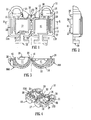
Fig. 1 is a plan view of the co-moulded housing of the illumination device in its initial open condition; -
Fig. 2 is a side view as viewed from the right inFig. 1 ; -
Fig. 3 is a cross-section along line A - A inFig. 1 ; -
Fig. 4 is a perspective view of the co-moulded housing ofFigs. 1 to 3 ; -
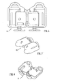
Fig. 5 is a plan view of the outer casing only of the housing ofFig. 1 , for comparison withFig. 1 ; -
Fig. 6 is a perspective view of the outer casing only of the housing, for comparison withFig. 4 ; -
Fig. 7 is a perspective view of the outer casing of the housing shown inFigs. 5 and 6 , but turned over to show its external contour; -
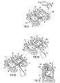
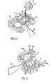
Figs. 8, 9 A, B, C ,10 and 11 show the sequence of operations in assembly of the device; -
Fig. 12 is a front view of the assembled device, with the pull tab only partially shown; -
Fig. 13 is a corresponding rear view of the assembled device; -
Fig. 14 is a corresponding side view, viewed from the right ofFig. 12 , of the assembled device, again with the pull tab shown only partially; -
Fig. 15 is a reduced scale side view, corresponding toFig. 14 , so as to include the full pull tab and indicate its size in relation to the housing; and -
Figs. 16 and 17 are schematic drawings of the previously mentioned prior art illumination device mounted inside the balloon prior to and after inflation, respectively. - With reference to the drawings, a preferred practical embodiment of the illumination device of the invention comprises four separate parts for assembly, namely:
- a co-moulded one-
piece housing 10, as shown infigures 1 to 4 ; - a light emitting diode (LED) 20 provided with
contact members figure 8 , but also appearing infigures 9 to 11 ; - two
button cell batteries figures 10 and 11 ; and - a strip of
insulating material 40, shown partially infigures 9 to 14 , and only fully infigure 15 . - The
housing 10 is formed with anintegral projection 18 having aneck 19 and an enlargedhead 17 by means of which the housing is to be mounted inside a balloon (not shown) by an elastic band (not shown) engaging from outside the balloon wall around theneck 19 of theprojection 18. Thehead 17 is in the form of a flattened button, ie. a generally circular disc. Theprojection 18 is, accordingly, T-shaped in cross-section. Thestrip 40 of insulating material is initially located so that a portion of saidstrip 40 extends between thebattery power source contact member 22 of theLED 20. In the fully assembled device, as shown inFigures 12 to 15 , thestrip 40 extends out of thehousing 10 as a pull tab. When this is pulled out, theLED 20 is connected to thebatteries device 10 is mounted into the initially uninflated balloon, thepull tab 40 extends out of the neck of the balloon. It has an enlarged arrow-shaped end region 42 which remains outside the neck of the balloon and provides suitable means for manual gripping and pulling by an end user who is to inflate and illuminate the balloon. An additional enlargedregion 44 spaced from the arrow-shaped end region 42 is provided to lodge in the neck region of the initially uninflated balloon to hold the pull tab in position and minimise risk of its inadvertent pulling out or removal by other means during storage and transport between balloon assembly and final use. - As illustrated in
Figs. 1 to 4 , thehousing 10 is formed in one piece as twomating sections inner part 12, and a second plastics material, such as a thermoplastic elastomer, providing anouter casing 14. The first plastics material has greater rigidity than the second material. The second material is resiliently deformable. - As best shown in
Figs. 1, 3 and 4 , both theinner part 12 and theouter casing 14 form parts of therespective mating sections hinge connection 16 between these sections. Thus both the first plastics material of theinner part 12 and the second plastics material of theouter casing 14 provide part of each of themating sections LED 20 and thebatteries projection 18, substantially one half of which is formed by each of themating sections entire projection 18. - The
inner part 12 provides areceptacle 11 for thebatteries guide channels LED contact elements receptacle 21 for a lower part of the LED from which the contact elements extend. Theinner part 12 is moulded with an integralspring element portion 25 in the manner of a leaf spring. Thisintegral spring element 25 is at an end of thebattery receptacle 11 remote from theLED receptacle 21 and is formed in only one of themating sections 10A of the housing. Thesame mating section 10A has itsinner part 12 of larger size than that of theother mating section 10B, thereby forming anupstand 41 protruding above the mating edge of the respectiveouter casing 14 of thatmating section 10A, as shown inFig. 3 . Accordingly, thismating section 10A accommodates more than half the cross-sectional area of the cylindrical shape of thebutton cell batteries - The
inner part 12 includes strips ofmaterial 33 configured to provide part of thehinge connection 16 between the twomating parts inner part 12 could provide the entirety of thehinge connection 16. - The
inner part 12 is also formed with latch projections and co-acting engagement recesses on therespective mating sections latch projections section 10B with aco-operating recess 28 formed in thesection 10A. Additionally there is afurther latch projection 29 near theLED recess 11 of themating section 10A and aco-operating recess 39 in thesection 10B. - The
outer casing 14 is of transparent plastics material. A suitable plastics is a thermo plastic vulcanizate TPV. As mentioned, this plastics material is resiliently deformable. It preferably has a co-efficient of restitution in the range 0.4 to 0.6 - The second plastics material of the outer casing surrounds, as an outer shell, all of the inner part, in both
mating sections hinge connection 16, with the sole exception of theprojection 18, where thehead 17 is covered only on its underside facing the main housing (or optionally not at all in a modified embodiment). This is appropriate as there is no need for full enclosure of thehead 17. It saves on the more expensive TPV material and simplifies the moulding production process. Also, the application of the elastic band when the device is subsequently mounted to the balloon wall may be facilitated with a projecting head which is predominantly of the substantially rigid first plastics material making it easier to grip and hold. - The
outer casing 14 completes the receptacle for theLED 20, for which it provides a transparent cover. - The overall configuration of the
outer casing 14 above is shown for purposes of illustration only inFigures 5, 6 and 7 so that this can be contrasted with the co-moulding 12, 14 ofFigures 1 to 4 . However, it will be understood that in practice in preferred embodiments of the invention theouter casing 14 is not actually produced as a separate part as the inner andouter parts outer parts - A typical thickness for the material of the
outer casing 14 is in the range 0.5mm to 1.0mm. - Each of the
mating sections narrow slot 34 cut in from the open, mating edge, extending through both theouter casing 14 and theinner part 12 from the exterior to thebattery receptacle 11 at a location between the hinge connection and theLED receptacle 21. However, in modified embodiments such aslot 34 may be provided only in themating section 10A which provides thespring element 25, and/or in a different location. - The
LED 20, as shown inFig. 8 , has itsfirst contact element 22 of shorter length and bent laterally and itssecond contact element 24 of longer length and bent in an L shape to provide a distal limb parallel with thefirst contact 22. - The steps in the assembly of the components to form the completed illumination device are illustrated in
Figs. 8 to 11 . - First, as shown in
Fig. 8 with thehousing 10 in its open disposition, as produced from the co-moulding process, theLED 20 with itspre-bent contact elements section 10A. - The
LED 20 is a snug fit into the receptacle half provided by thissection 10A and thecontact elements guide channels longer contact element 24 overlies and is spring biased by thespring element portion 25. This is shown clearly in the cross-section view ofFig. 9C . - Second, as shown in
Figs. 9 A and B , a location near the end of thestrip 40 is inserted into theslot 34 of thesection 10A and guided to have its end portion extending below theshorter contact element 22 of theLED 20. Again this is most clearly seen in the cross-section view ofFig. 9C . - Thirdly, as shown in
Fig. 10 , the twobutton cell batteries same section 10A. It is simple to ensure that thefirst battery 31 is located against the firstLED contact element 22, with the end portion of thestrip 40 extending therebetween, and that thesecond battery 32 is located between thefirst battery 31 and the secondLED contact element 24. Thespring element 25 acting on thesecond contact element 24 ensures that thesebatteries upstand 41 of theinner part 12 in thesection 10A, beyond the 180° diameter of thebatteries - The
housing 10 is then closed, as shown inFig. 11 , by swinging over themating section 10B about thehinge 16 and engagement of therespective latch formations complimentary recesses respective mating sections strip 40 should, if necessary, be guided to locate through the correspondingslot 34 of thesection 10B before the clip connection is completed. In other words, it should be ensured that the strip/pull tab 40 is not trapped between thesections - The finished assembly is shown in all of
Figs. 12 to 15 . The device is then ready for mounting inside a balloon in the manner previously explained. - The foregoing is illustrative and not limitative of the scope of the invention. Many variations in detail of the design are possible in other embodiments within the scope of the appended claims. In particular, the material chosen for the inner and outer parts of the housing may differ and may be any suitable plastics or other material. The detailed configuration of the various components may vary. In other embodiments the housing may not be in one piece, nor have mating sections. Also the light source may be other than an LED. In a slightly modified version of the device, the outer casing may include an additional flap, maybe of just 1 mm width, extending from the mating edge of either the
housing section 10A or thehousing section 10B, particularly in the region where these abut over the LED, to overlap the adjacent edge of the other housing section, so as to ensure that there is no gap and the LED at least is fully enclosed and protected.
Claims (15)
- An illumination device for mounting inside a balloon formed by a wall of flexible material which is at least partially transparent or translucent, the illumination device comprising a housing (10), and a light source (20) and a battery power source (31, 32) for the light source (20) mounted within the housing (10),
characterised in that the housing (10) is provided as an inner part (12) of a first plastics material in which the battery power source (31, 32) is housed and an outer casing (14) of a second plastics material which at least partially surrounds the inner part (12) and provides a cover for the light source (20), the second plastics material being transparent and being resiliently deformable, and the housing (10) is provided as at least one co-moulding of the first plastics material and the second plastics material. - An illumination device as claimed in claim 1 wherein the light source (20) has first and second connector members (22, 24) and at least one of said first and second connector members (22, 24) projects to contact a respective terminal of the battery power source (31, 32), and the first plastics material includes an integrally formed spring element portion (25) which is configured and arranged to hold at least one of said first and second connector members (22, 24) and/or the battery power source (31, 32) under spring bias to maintain contact there between.
- An illumination device as claimed in claim 2 wherein the housing (10) is provided as a one-piece unit.
- An illumination device as claimed in any preceding claim wherein the housing (10) has an outward projection (18) in the form of a pin with a neck (19) and an enlarged head (17) whereby it is attachable to the wall of the balloon by engagement from outside by an attachment element such as a band or clip.
- An illumination device as claimed in claim 4 wherein the projection (18) is at least partially formed of the first plastics material as an extended portion of the inner part (12) of the housing (10).
- An illumination device as claimed in any preceding claim wherein a removable strip of insulating material (40) is initially arranged to have an end portion disposed directly between one of the first and second connector members (22, 24) and the respective terminal of the battery power source (31, 32).
- An illumination device as claimed in any preceding claim wherein the housing (10) is provided as two mating sections (10A, 10B).
- An illumination device as claimed in claims 6 and 7 wherein at least one of the mating sections (10A, 10B) has a slot (34) extending from a mating edge through which the insulating strip (40) passes to provide an externally accessible pull tab (42).
- An illumination device as claimed in claim 7 or 8 wherein the two mating sections (10A, 10B) are hingedly connected to each other by a hinge portion (16) which is at least partially formed of the first plastics material as a portion of the inner part (12) of the housing (10).
- An illumination device as claimed in any of claims 7 to 9 wherein the mating sections (10A, 10B) are fastened together by at least one latch formation (26, 27) which is formed of the first plastics material and provided integrally with the inner part (12) of the housing (10).
- An illumination device as claimed in any of claims 7 to 10 wherein the inner part (12) of the first of the two mating sections (10A) is larger than the inner part (12) of the second of the mating sections (10B) and is configured to accommodate more than half of the cross-sectional area of the battery power source (31, 32) which is housed in the mated inner parts (12) of the said mating sections (10A, 10B).
- An illumination device as claimed in any preceding claim wherein the second plastics material has a co-efficient of restitution in the range of 0.4 to 0.6.
- An illumination device as claimed in any preceding claim wherein the second plastics material has a thickness in a range between 0.5mm and 1.0 mm where it serves as an outer casing surrounding the inner part (12).
- An illumination device as claimed in any preceding claim wherein the second plastics material is thermoplastics elastomer.
- An illumination device as claim in claim 14 wherein the second plastics material is an elastomeric alloy or thermoplastic vulcinizate (TPV).
Priority Applications (1)
| Application Number | Priority Date | Filing Date | Title |
|---|---|---|---|
| PL12731626T PL2723464T3 (en) | 2011-06-21 | 2012-06-19 | An illumination device for a balloon |
Applications Claiming Priority (2)
| Application Number | Priority Date | Filing Date | Title |
|---|---|---|---|
| GB1110437.9A GB2492092A (en) | 2011-06-21 | 2011-06-21 | An illumination device for a balloon |
| PCT/GB2012/051404 WO2012175945A1 (en) | 2011-06-21 | 2012-06-19 | An illumination device for a balloon |
Publications (2)
| Publication Number | Publication Date |
|---|---|
| EP2723464A1 EP2723464A1 (en) | 2014-04-30 |
| EP2723464B1 true EP2723464B1 (en) | 2015-07-22 |
Family
ID=44454361
Family Applications (1)
| Application Number | Title | Priority Date | Filing Date |
|---|---|---|---|
| EP12731626.3A Active EP2723464B1 (en) | 2011-06-21 | 2012-06-19 | An illumination device for a balloon |
Country Status (9)
| Country | Link |
|---|---|
| US (1) | US9316364B2 (en) |
| EP (1) | EP2723464B1 (en) |
| CN (1) | CN202546625U (en) |
| DK (1) | DK2723464T3 (en) |
| ES (1) | ES2548843T3 (en) |
| GB (1) | GB2492092A (en) |
| PL (1) | PL2723464T3 (en) |
| PT (1) | PT2723464E (en) |
| WO (1) | WO2012175945A1 (en) |
Families Citing this family (6)
| Publication number | Priority date | Publication date | Assignee | Title |
|---|---|---|---|---|
| GB2507508B (en) * | 2012-10-30 | 2017-09-27 | Seatriever Int Holdings Ltd | Tear resistant moulded articles |
| DE202014100254U1 (en) * | 2014-01-22 | 2015-04-24 | Reiko Denisz | balloon unit |
| WO2016069884A2 (en) | 2014-10-29 | 2016-05-06 | Altria Client Services Llc | E-vaping section for an e-vaping device |
| CN107019919A (en) * | 2016-01-29 | 2017-08-08 | 浙江飞麦光电科技有限公司 | Multifunctional LED lighted balloons |
| CN109276892A (en) * | 2018-03-28 | 2019-01-29 | 义乌豪格贸易有限公司 | Lighted balloons with integral type card chamber |
| US11425949B1 (en) | 2021-08-20 | 2022-08-30 | Barrett Reek | Balloon headdress |
Family Cites Families (7)
| Publication number | Priority date | Publication date | Assignee | Title |
|---|---|---|---|---|
| DE3015962A1 (en) * | 1980-04-25 | 1981-11-05 | Anton 7500 Karlsruhe Szollmann | Inflatable balloon holder and illuminator - has rod-shaped lamp without optics, plug for balloon inflation and non-return valve coupled to tube from plug |
| US6390651B2 (en) | 1999-12-09 | 2002-05-21 | Timothy R. Bertrand | Toy with balloon and lighting apparatus |
| US7147536B1 (en) * | 2003-06-26 | 2006-12-12 | Hartelius Mark E | Balloon inflating and illuminating device |
| EP1600690A1 (en) | 2004-05-25 | 2005-11-30 | Shu-Lien Tang | Lighting device for illuminating a balloon from within |
| GB2452236A (en) | 2007-03-09 | 2009-03-04 | Mellowgraphic Ltd | Party balloon with illumination device |
| GB201002031D0 (en) * | 2010-02-08 | 2010-03-24 | Seatriever Internat Holdings L | An attachment device |
| CN203564782U (en) * | 2013-07-01 | 2014-04-30 | 天津天龙化学发光管有限公司 | Light-emitting balloon |
-
2011
- 2011-06-21 GB GB1110437.9A patent/GB2492092A/en not_active Withdrawn
- 2011-12-09 CN CN201120523269XU patent/CN202546625U/en not_active Expired - Lifetime
-
2012
- 2012-06-19 EP EP12731626.3A patent/EP2723464B1/en active Active
- 2012-06-19 PL PL12731626T patent/PL2723464T3/en unknown
- 2012-06-19 US US14/127,335 patent/US9316364B2/en active Active
- 2012-06-19 ES ES12731626.3T patent/ES2548843T3/en active Active
- 2012-06-19 DK DK12731626.3T patent/DK2723464T3/en active
- 2012-06-19 PT PT127316263T patent/PT2723464E/en unknown
- 2012-06-19 WO PCT/GB2012/051404 patent/WO2012175945A1/en not_active Ceased
Also Published As
| Publication number | Publication date |
|---|---|
| PL2723464T3 (en) | 2015-12-31 |
| GB201110437D0 (en) | 2011-08-03 |
| US9316364B2 (en) | 2016-04-19 |
| GB2492092A (en) | 2012-12-26 |
| ES2548843T3 (en) | 2015-10-21 |
| PT2723464E (en) | 2015-10-23 |
| DK2723464T3 (en) | 2015-10-12 |
| CN202546625U (en) | 2012-11-21 |
| US20140168960A1 (en) | 2014-06-19 |
| WO2012175945A1 (en) | 2012-12-27 |
| EP2723464A1 (en) | 2014-04-30 |
Similar Documents
| Publication | Publication Date | Title |
|---|---|---|
| WO2012175946A1 (en) | An illumination device for a balloon | |
| US9316364B2 (en) | Illumination device for a balloon | |
| US9534749B2 (en) | Light transmitting slap wrist device | |
| US9195076B2 (en) | Accessory for glasses | |
| ES2280791T3 (en) | BABERO INFANTIL THAT HAS A CLOSURE OF CORD OF ACCOUNTS. | |
| US20140027521A1 (en) | Insert for enclosing electronics | |
| USD520521S1 (en) | Battery-powered pressure pump for liquid and lotion applicators | |
| US10751637B1 (en) | Wearable and illuminating wings | |
| KR101798675B1 (en) | An attachment device for attachment to a membrane, e.g. of balloon, without puncturing the membrane | |
| EP3149545A1 (en) | Battery compartments for wearable electronic device | |
| US6598991B2 (en) | Miniature flashlight device | |
| CA2679777A1 (en) | Party balloon with illumination device | |
| US11248777B2 (en) | Systems and methods for a rechargeable lighting module and associated carrier | |
| US20170227202A1 (en) | Illuminable Key Chain | |
| US9186594B2 (en) | Illuminated balloon | |
| TWI851604B (en) | Handles for poles, ski poles, and walking sticks | |
| CN112513521A (en) | Headlamp integrated into a flexible composite headband | |
| US20160100675A1 (en) | Safety Arm Band for Mobile Devices | |
| USD639374S1 (en) | Protector for a life vest | |
| CN108835780B (en) | Intelligent bracelet | |
| KR101443538B1 (en) | Dual cover assembly for personal communication devices capable of inserting card means | |
| CN211741843U (en) | Anti-falling quartz watch | |
| US4044499A (en) | Whirl toy | |
| CN219229073U (en) | Waistcoat for assisting visually impaired people in traveling | |
| JP3175864U (en) | Cover case for portable terminal |
Legal Events
| Date | Code | Title | Description |
|---|---|---|---|
| PUAI | Public reference made under article 153(3) epc to a published international application that has entered the european phase |
Free format text: ORIGINAL CODE: 0009012 |
|
| 17P | Request for examination filed |
Effective date: 20140103 |
|
| AK | Designated contracting states |
Kind code of ref document: A1 Designated state(s): AL AT BE BG CH CY CZ DE DK EE ES FI FR GB GR HR HU IE IS IT LI LT LU LV MC MK MT NL NO PL PT RO RS SE SI SK SM TR |
|
| DAX | Request for extension of the european patent (deleted) | ||
| GRAP | Despatch of communication of intention to grant a patent |
Free format text: ORIGINAL CODE: EPIDOSNIGR1 |
|
| INTG | Intention to grant announced |
Effective date: 20150206 |
|
| GRAS | Grant fee paid |
Free format text: ORIGINAL CODE: EPIDOSNIGR3 |
|
| GRAA | (expected) grant |
Free format text: ORIGINAL CODE: 0009210 |
|
| RAP1 | Party data changed (applicant data changed or rights of an application transferred) |
Owner name: SEATRIEVER INTERNATIONAL HOLDINGS LIMITED |
|
| AK | Designated contracting states |
Kind code of ref document: B1 Designated state(s): AL AT BE BG CH CY CZ DE DK EE ES FI FR GB GR HR HU IE IS IT LI LT LU LV MC MK MT NL NO PL PT RO RS SE SI SK SM TR |
|
| REG | Reference to a national code |
Ref country code: GB Ref legal event code: FG4D |
|
| REG | Reference to a national code |
Ref country code: CH Ref legal event code: EP |
|
| REG | Reference to a national code |
Ref country code: IE Ref legal event code: FG4D |
|
| REG | Reference to a national code |
Ref country code: AT Ref legal event code: REF Ref document number: 737560 Country of ref document: AT Kind code of ref document: T Effective date: 20150815 |
|
| REG | Reference to a national code |
Ref country code: DE Ref legal event code: R096 Ref document number: 602012008981 Country of ref document: DE |
|
| REG | Reference to a national code |
Ref country code: DK Ref legal event code: T3 Effective date: 20151006 |
|
| REG | Reference to a national code |
Ref country code: CH Ref legal event code: NV Representative=s name: MICHELI AND CIE SA, CH |
|
| REG | Reference to a national code |
Ref country code: SE Ref legal event code: TRGR |
|
| REG | Reference to a national code |
Ref country code: ES Ref legal event code: FG2A Ref document number: 2548843 Country of ref document: ES Kind code of ref document: T3 Effective date: 20151021 |
|
| REG | Reference to a national code |
Ref country code: PT Ref legal event code: SC4A Free format text: AVAILABILITY OF NATIONAL TRANSLATION Effective date: 20151001 |
|
| REG | Reference to a national code |
Ref country code: NL Ref legal event code: FP |
|
| REG | Reference to a national code |
Ref country code: AT Ref legal event code: MK05 Ref document number: 737560 Country of ref document: AT Kind code of ref document: T Effective date: 20150722 |
|
| REG | Reference to a national code |
Ref country code: LT Ref legal event code: MG4D |
|
| REG | Reference to a national code |
Ref country code: PL Ref legal event code: T3 |
|
| PG25 | Lapsed in a contracting state [announced via postgrant information from national office to epo] |
Ref country code: LV Free format text: LAPSE BECAUSE OF FAILURE TO SUBMIT A TRANSLATION OF THE DESCRIPTION OR TO PAY THE FEE WITHIN THE PRESCRIBED TIME-LIMIT Effective date: 20150722 Ref country code: LT Free format text: LAPSE BECAUSE OF FAILURE TO SUBMIT A TRANSLATION OF THE DESCRIPTION OR TO PAY THE FEE WITHIN THE PRESCRIBED TIME-LIMIT Effective date: 20150722 Ref country code: FI Free format text: LAPSE BECAUSE OF FAILURE TO SUBMIT A TRANSLATION OF THE DESCRIPTION OR TO PAY THE FEE WITHIN THE PRESCRIBED TIME-LIMIT Effective date: 20150722 Ref country code: GR Free format text: LAPSE BECAUSE OF FAILURE TO SUBMIT A TRANSLATION OF THE DESCRIPTION OR TO PAY THE FEE WITHIN THE PRESCRIBED TIME-LIMIT Effective date: 20151023 Ref country code: NO Free format text: LAPSE BECAUSE OF FAILURE TO SUBMIT A TRANSLATION OF THE DESCRIPTION OR TO PAY THE FEE WITHIN THE PRESCRIBED TIME-LIMIT Effective date: 20151022 |
|
| PG25 | Lapsed in a contracting state [announced via postgrant information from national office to epo] |
Ref country code: AT Free format text: LAPSE BECAUSE OF FAILURE TO SUBMIT A TRANSLATION OF THE DESCRIPTION OR TO PAY THE FEE WITHIN THE PRESCRIBED TIME-LIMIT Effective date: 20150722 Ref country code: RS Free format text: LAPSE BECAUSE OF FAILURE TO SUBMIT A TRANSLATION OF THE DESCRIPTION OR TO PAY THE FEE WITHIN THE PRESCRIBED TIME-LIMIT Effective date: 20150722 Ref country code: IS Free format text: LAPSE BECAUSE OF FAILURE TO SUBMIT A TRANSLATION OF THE DESCRIPTION OR TO PAY THE FEE WITHIN THE PRESCRIBED TIME-LIMIT Effective date: 20151122 Ref country code: HR Free format text: LAPSE BECAUSE OF FAILURE TO SUBMIT A TRANSLATION OF THE DESCRIPTION OR TO PAY THE FEE WITHIN THE PRESCRIBED TIME-LIMIT Effective date: 20150722 |
|
| REG | Reference to a national code |
Ref country code: DE Ref legal event code: R097 Ref document number: 602012008981 Country of ref document: DE |
|
| PG25 | Lapsed in a contracting state [announced via postgrant information from national office to epo] |
Ref country code: EE Free format text: LAPSE BECAUSE OF FAILURE TO SUBMIT A TRANSLATION OF THE DESCRIPTION OR TO PAY THE FEE WITHIN THE PRESCRIBED TIME-LIMIT Effective date: 20150722 Ref country code: SK Free format text: LAPSE BECAUSE OF FAILURE TO SUBMIT A TRANSLATION OF THE DESCRIPTION OR TO PAY THE FEE WITHIN THE PRESCRIBED TIME-LIMIT Effective date: 20150722 Ref country code: CZ Free format text: LAPSE BECAUSE OF FAILURE TO SUBMIT A TRANSLATION OF THE DESCRIPTION OR TO PAY THE FEE WITHIN THE PRESCRIBED TIME-LIMIT Effective date: 20150722 |
|
| PLBE | No opposition filed within time limit |
Free format text: ORIGINAL CODE: 0009261 |
|
| STAA | Information on the status of an ep patent application or granted ep patent |
Free format text: STATUS: NO OPPOSITION FILED WITHIN TIME LIMIT |
|
| REG | Reference to a national code |
Ref country code: DE Ref legal event code: R082 Ref document number: 602012008981 Country of ref document: DE Representative=s name: HERNANDEZ, YORCK, DIPL.-ING., DE |
|
| PG25 | Lapsed in a contracting state [announced via postgrant information from national office to epo] |
Ref country code: RO Free format text: LAPSE BECAUSE OF FAILURE TO SUBMIT A TRANSLATION OF THE DESCRIPTION OR TO PAY THE FEE WITHIN THE PRESCRIBED TIME-LIMIT Effective date: 20150722 |
|
| REG | Reference to a national code |
Ref country code: FR Ref legal event code: PLFP Year of fee payment: 5 |
|
| 26N | No opposition filed |
Effective date: 20160425 |
|
| PG25 | Lapsed in a contracting state [announced via postgrant information from national office to epo] |
Ref country code: SI Free format text: LAPSE BECAUSE OF FAILURE TO SUBMIT A TRANSLATION OF THE DESCRIPTION OR TO PAY THE FEE WITHIN THE PRESCRIBED TIME-LIMIT Effective date: 20150722 |
|
| PG25 | Lapsed in a contracting state [announced via postgrant information from national office to epo] |
Ref country code: BE Free format text: LAPSE BECAUSE OF FAILURE TO SUBMIT A TRANSLATION OF THE DESCRIPTION OR TO PAY THE FEE WITHIN THE PRESCRIBED TIME-LIMIT Effective date: 20150722 |
|
| PG25 | Lapsed in a contracting state [announced via postgrant information from national office to epo] |
Ref country code: MC Free format text: LAPSE BECAUSE OF FAILURE TO SUBMIT A TRANSLATION OF THE DESCRIPTION OR TO PAY THE FEE WITHIN THE PRESCRIBED TIME-LIMIT Effective date: 20150722 |
|
| REG | Reference to a national code |
Ref country code: FR Ref legal event code: PLFP Year of fee payment: 6 |
|
| PG25 | Lapsed in a contracting state [announced via postgrant information from national office to epo] |
Ref country code: HU Free format text: LAPSE BECAUSE OF FAILURE TO SUBMIT A TRANSLATION OF THE DESCRIPTION OR TO PAY THE FEE WITHIN THE PRESCRIBED TIME-LIMIT; INVALID AB INITIO Effective date: 20120619 Ref country code: SM Free format text: LAPSE BECAUSE OF FAILURE TO SUBMIT A TRANSLATION OF THE DESCRIPTION OR TO PAY THE FEE WITHIN THE PRESCRIBED TIME-LIMIT Effective date: 20150722 |
|
| REG | Reference to a national code |
Ref country code: FR Ref legal event code: PLFP Year of fee payment: 7 |
|
| PG25 | Lapsed in a contracting state [announced via postgrant information from national office to epo] |
Ref country code: MT Free format text: LAPSE BECAUSE OF NON-PAYMENT OF DUE FEES Effective date: 20160630 Ref country code: MK Free format text: LAPSE BECAUSE OF FAILURE TO SUBMIT A TRANSLATION OF THE DESCRIPTION OR TO PAY THE FEE WITHIN THE PRESCRIBED TIME-LIMIT Effective date: 20150722 Ref country code: CY Free format text: LAPSE BECAUSE OF FAILURE TO SUBMIT A TRANSLATION OF THE DESCRIPTION OR TO PAY THE FEE WITHIN THE PRESCRIBED TIME-LIMIT Effective date: 20150722 Ref country code: TR Free format text: LAPSE BECAUSE OF FAILURE TO SUBMIT A TRANSLATION OF THE DESCRIPTION OR TO PAY THE FEE WITHIN THE PRESCRIBED TIME-LIMIT Effective date: 20150722 Ref country code: LU Free format text: LAPSE BECAUSE OF NON-PAYMENT OF DUE FEES Effective date: 20160619 |
|
| PG25 | Lapsed in a contracting state [announced via postgrant information from national office to epo] |
Ref country code: BG Free format text: LAPSE BECAUSE OF FAILURE TO SUBMIT A TRANSLATION OF THE DESCRIPTION OR TO PAY THE FEE WITHIN THE PRESCRIBED TIME-LIMIT Effective date: 20150722 |
|
| PG25 | Lapsed in a contracting state [announced via postgrant information from national office to epo] |
Ref country code: AL Free format text: LAPSE BECAUSE OF FAILURE TO SUBMIT A TRANSLATION OF THE DESCRIPTION OR TO PAY THE FEE WITHIN THE PRESCRIBED TIME-LIMIT Effective date: 20150722 |
|
| PGFP | Annual fee paid to national office [announced via postgrant information from national office to epo] |
Ref country code: NO Payment date: 20190524 Year of fee payment: 8 Ref country code: PT Payment date: 20190618 Year of fee payment: 8 |
|
| PGFP | Annual fee paid to national office [announced via postgrant information from national office to epo] |
Ref country code: SE Payment date: 20190625 Year of fee payment: 8 |
|
| PGFP | Annual fee paid to national office [announced via postgrant information from national office to epo] |
Ref country code: CH Payment date: 20190625 Year of fee payment: 8 |
|
| PGFP | Annual fee paid to national office [announced via postgrant information from national office to epo] |
Ref country code: IE Payment date: 20200612 Year of fee payment: 9 |
|
| REG | Reference to a national code |
Ref country code: DK Ref legal event code: EBP Effective date: 20200630 |
|
| REG | Reference to a national code |
Ref country code: CH Ref legal event code: PL |
|
| PG25 | Lapsed in a contracting state [announced via postgrant information from national office to epo] |
Ref country code: CH Free format text: LAPSE BECAUSE OF NON-PAYMENT OF DUE FEES Effective date: 20200630 Ref country code: LI Free format text: LAPSE BECAUSE OF NON-PAYMENT OF DUE FEES Effective date: 20200630 Ref country code: PT Free format text: LAPSE BECAUSE OF NON-PAYMENT OF DUE FEES Effective date: 20210122 |
|
| PG25 | Lapsed in a contracting state [announced via postgrant information from national office to epo] |
Ref country code: SE Free format text: LAPSE BECAUSE OF NON-PAYMENT OF DUE FEES Effective date: 20200620 |
|
| PG25 | Lapsed in a contracting state [announced via postgrant information from national office to epo] |
Ref country code: DK Free format text: LAPSE BECAUSE OF NON-PAYMENT OF DUE FEES Effective date: 20200630 |
|
| REG | Reference to a national code |
Ref country code: SE Ref legal event code: EUG |
|
| PG25 | Lapsed in a contracting state [announced via postgrant information from national office to epo] |
Ref country code: IE Free format text: LAPSE BECAUSE OF NON-PAYMENT OF DUE FEES Effective date: 20210619 |
|
| P01 | Opt-out of the competence of the unified patent court (upc) registered |
Effective date: 20230510 |
|
| PGFP | Annual fee paid to national office [announced via postgrant information from national office to epo] |
Ref country code: NL Payment date: 20240617 Year of fee payment: 13 |
|
| PGFP | Annual fee paid to national office [announced via postgrant information from national office to epo] |
Ref country code: PL Payment date: 20250613 Year of fee payment: 14 Ref country code: DE Payment date: 20250618 Year of fee payment: 14 |
|
| PGFP | Annual fee paid to national office [announced via postgrant information from national office to epo] |
Ref country code: GB Payment date: 20250617 Year of fee payment: 14 |
|
| PGFP | Annual fee paid to national office [announced via postgrant information from national office to epo] |
Ref country code: FR Payment date: 20250620 Year of fee payment: 14 |
|
| PGFP | Annual fee paid to national office [announced via postgrant information from national office to epo] |
Ref country code: ES Payment date: 20250704 Year of fee payment: 14 |
|
| PGFP | Annual fee paid to national office [announced via postgrant information from national office to epo] |
Ref country code: IT Payment date: 20250619 Year of fee payment: 14 |
|
| REG | Reference to a national code |
Ref country code: NL Ref legal event code: MM Effective date: 20250701 |
|
| PG25 | Lapsed in a contracting state [announced via postgrant information from national office to epo] |
Ref country code: NL Free format text: LAPSE BECAUSE OF NON-PAYMENT OF DUE FEES Effective date: 20250701 |