EP2722977A2 - Method and apparatus for controlling a start-up sequence of a DC/DC Buck converter - Google Patents
Method and apparatus for controlling a start-up sequence of a DC/DC Buck converter Download PDFInfo
- Publication number
- EP2722977A2 EP2722977A2 EP13162641.8A EP13162641A EP2722977A2 EP 2722977 A2 EP2722977 A2 EP 2722977A2 EP 13162641 A EP13162641 A EP 13162641A EP 2722977 A2 EP2722977 A2 EP 2722977A2
- Authority
- EP
- European Patent Office
- Prior art keywords
- buck converter
- output
- voltage
- reference voltage
- output voltage
- Prior art date
- Legal status (The legal status is an assumption and is not a legal conclusion. Google has not performed a legal analysis and makes no representation as to the accuracy of the status listed.)
- Withdrawn
Links
Images



Classifications
-
- H—ELECTRICITY
- H02—GENERATION; CONVERSION OR DISTRIBUTION OF ELECTRIC POWER
- H02M—APPARATUS FOR CONVERSION BETWEEN AC AND AC, BETWEEN AC AND DC, OR BETWEEN DC AND DC, AND FOR USE WITH MAINS OR SIMILAR POWER SUPPLY SYSTEMS; CONVERSION OF DC OR AC INPUT POWER INTO SURGE OUTPUT POWER; CONTROL OR REGULATION THEREOF
- H02M1/00—Details of apparatus for conversion
- H02M1/36—Means for starting or stopping converters
-
- H—ELECTRICITY
- H02—GENERATION; CONVERSION OR DISTRIBUTION OF ELECTRIC POWER
- H02M—APPARATUS FOR CONVERSION BETWEEN AC AND AC, BETWEEN AC AND DC, OR BETWEEN DC AND DC, AND FOR USE WITH MAINS OR SIMILAR POWER SUPPLY SYSTEMS; CONVERSION OF DC OR AC INPUT POWER INTO SURGE OUTPUT POWER; CONTROL OR REGULATION THEREOF
- H02M3/00—Conversion of DC power input into DC power output
- H02M3/02—Conversion of DC power input into DC power output without intermediate conversion into AC
- H02M3/04—Conversion of DC power input into DC power output without intermediate conversion into AC by static converters
- H02M3/10—Conversion of DC power input into DC power output without intermediate conversion into AC by static converters using discharge tubes with control electrode or semiconductor devices with control electrode
- H02M3/145—Conversion of DC power input into DC power output without intermediate conversion into AC by static converters using discharge tubes with control electrode or semiconductor devices with control electrode using devices of a triode or transistor type requiring continuous application of a control signal
- H02M3/155—Conversion of DC power input into DC power output without intermediate conversion into AC by static converters using discharge tubes with control electrode or semiconductor devices with control electrode using devices of a triode or transistor type requiring continuous application of a control signal using semiconductor devices only
- H02M3/156—Conversion of DC power input into DC power output without intermediate conversion into AC by static converters using discharge tubes with control electrode or semiconductor devices with control electrode using devices of a triode or transistor type requiring continuous application of a control signal using semiconductor devices only with automatic control of output voltage or current, e.g. switching regulators
- H02M3/158—Conversion of DC power input into DC power output without intermediate conversion into AC by static converters using discharge tubes with control electrode or semiconductor devices with control electrode using devices of a triode or transistor type requiring continuous application of a control signal using semiconductor devices only with automatic control of output voltage or current, e.g. switching regulators including plural semiconductor devices as final control devices for a single load
Definitions
- This invention relates to Buck DC/DC voltage converters, and more particularly, but without limitation, to a method and apparatus for controlling a start-up sequence of a DC/DC Buck converter.
- a Buck converter provides a convenient way to reduce the voltage of a DC power supply from that of, say a battery at 12V, to the low voltages required by integrated circuits, which are typically less than 1V.
- Buck converters employ an inductor and a capacitor to step-down an applied input voltage by relying on the inductor's reluctance to change its voltage as the applied input voltage is switched on and off repeatedly.
- the inductor will effectively fight the current, thus providing a voltage source that charges the capacitor, and when the input voltage is switched off, the voltage across the capacitor acts on the inductor in an opposite sense to input voltage to force the current in the inductor in an opposite direction.
- Buck converters are significantly more efficient than, say, potential dividers, which effectively dump excess power (cf. voltage) as heat, and so Buck converters find useful applications, in particular, in Integrated Circuits (IC) for wireless devices such as mobile terminal systems (e.g. cell phones, smart phones, etc.), digital media players (e.g. MP3 and MP4 players), DVD players, portable PCs, tablet PCs and so on.
- IC Integrated Circuits
- Buck converters suffer from a known problem of being difficult to restart on the fly, that is to say, being switched off for a few microseconds and then restarted, because they can be overstressed in such situations. Overstressing occurs when the input voltage suddenly drops to zero and is then re-applied before the capacitor has sufficiently discharged, which can give rise to a very high current magnitude that, in certain circumstances, can lead to the destruction of a connected IC.
- control routines need to be employed that wait for a pre-specified "minimum turn-off time" before starting the Buck converter again.
- the purpose of the minimum turn-off time which is typically around 1ms, is to allow the Buck converter's capacitor to discharge to a level that will restrict the current surge upon restart to within safe parameters, thereby protecting the connected IC.
- the "enable" command of an IC connected to, and which triggers the restart of, the Buck converter can be asynchronous.
- the IC necessarily requires the Buck converter to be able to start on the fly, regardless of the output capacitor's discharge status.
- the Buck converter can deliver a current that has the potential to damage the IC, and a need therefore exists to allow a restart on the fly, but without risking damaging the IC.
- a first aspect of the present invention relates to a method of controlling a start-up sequence of a DC/DC Buck converter.
- a second aspect of the present invention relates to a computer program product comprising one or more stored sequences of instructions that are accessible to a processor and which, when executed by the processor, cause the processor to carry out the steps of the method of the first aspect of the present invention.
- a third aspect of the present invention relates to an apparatus, for instance an Integrated Circuit (IC), comprising means for controlling a start-up sequence of a DC/DC Buck converter in accordance with the method of the first aspect.
- IC Integrated Circuit
- a fourth aspect of the present invention relates to a wireless device, e.g. among the examples given in the introduction, comprising a device according to second aspect.
- a fifth aspect of the invention provides a method of controlling a start-up sequence of a DC/DC Buck converter, the method being characterised by the steps of: continuously comparing the Buck converter's output voltage with an internal reference voltage and continuously monitoring for a Buck converter start-up signal, wherein if the output voltage is greater than the reference voltage when a Buck converter start-up signal is detected, switching off the Buck converter and discharging an output capacitor of the Buck converter through a pull-down unit until the output voltage substantially equals the internal reference voltage and then restarting the Buck converter.
- the method additionally comprises the keeping the Buck converter switched on when the output voltage is less than the reference voltage.
- a sixth aspect of the invention provides a DC/DC Buck converter comprising a start-up controller, characterised by: the start-up controller comprising a comparator operatively connected to, and adapted to compare a first voltage corresponding to an output voltage of the Buck converter a second voltage corresponding to an internal reference voltage, the output of the comparator providing a first input for an AND logic controller whose second input is operatively connected to a Buck converter start-up signal, wherein the AND logic controller is configured to switch off the Buck converter and to discharge an output capacitor of the Buck converter via a pull-down circuit AND logic controller's input are both in a logical state "1".
- the DC/DC Buck converter of the sixth aspect of the invention keeps the Buck converter switched on when the Buck converter's output voltage is less than the reference voltage.
- the DC/DC Buck converter of the sixth aspect of the invention is configured to switch of the Buck converter and to discharge the Buck converter's output capacitor when the Buck converter's output voltage is greater than the internal reference voltage simultaneously with a Buck converter start-up signal being detected. It will also be appreciated that the first logical input of the AND logic controller goes to logical state "0" when output voltage of the Buck converter falls below the internal reference voltage, indicating that the Buck converter's output capacitor has sufficiently discharged to allow the Buck converter to be safely re-started without a deep current inversion.
- the invention enables a DC/DC Buck converter to be re-started on the fly, without the risk of a deep current inversion.
- the output voltage of the Buck converter is maintained at a non-zero value during re-starting of the Buck converter.
- Suitable embodiments of the invention provide that if the start-up of the Buck converter might be dangerous, for example, if the output capacitor is charged too much, then the capacitor is discharged with the help of the pull-down unit. As soon as the state of the system is safe, that is to say, when the charge status of the output capacitor falls below a certain value, determined with reference to the output voltage relative to the internal reference voltage, then the invention enables the Buck converter to start. Suitably also, if the state of the system is safe when a start-up is requested, then the invention is configured to allow the Buck converter to be restarted without first discharging its output capacitor.
- a known DC/DC Buck converter 10 comprises an inductor coil 12 wired in series, and a capacitor 14 wired in parallel with an output 16 and an input 18.
- the input 18 is essentially a switching mechanism 20 that delivers a pulsed input voltage.
- the pulsing of the input voltage is generated by a ramp generator that feeds into one input 24 of a comparator 26, with the other input 28 being connected to the output of a second comparator 30.
- the second comparator 30 is connected, at one input 32, to the output voltage 34 of the converter 10, and at its other input 36 to a voltage generator that is driven by a current source 37.
- the current source 37 is connected to an input capacitor 38 to provide an internal reference voltage 42.
- the Buck converter's internal reference voltage 42 is generated as a ramp going from zero to a finite voltage 44.
- the internal reference voltage 42 is combined with a fixed voltage value 46 in a combining circuit 48 (as shown in Figure 1 ) to generate an output reference voltage 50 as follows:
- the output reference voltage 50 is given by internal reference voltage 42. As soon as the internal reference voltage 42 reaches the fixed voltage value 46, the output reference voltage 50 is equal to the fixed voltage value 46.
- the reference voltage seen internally that is to say, the internal reference voltage 50, is a ramp 54 starting from zero volts with a fixed slope until it equals the fixed voltage value 46.
- the output current 56 is sunk 60 by the power stage and thus the current inside the coil 12 of the Buck converter 10 is dependent on the ramp slope 54, and is given by the product of the capacitor's value 14 and the slope 54.
- the current 56 inside the coil 12 and thus the current output from the power stage does not have a deep current inversion during the start-up phase 58. Hence, there is only little, if no power stage overstress.
- FIG. 6 An embodiment of the invention is shown in Figure 6 , which comprises a DC/DC Buck converter 10 as described previously, but with the addition of a start-up controller 80 at the Buck converter's input.
- the start-up controller 80 solves the problem of deep current inversion in the Buck converter's output capacitor 14, which modifies the start-up phase and safely turns on the Buck converter 10, even if it is enabled asynchronously.
- the start-up controller 80 improves the design performance such that the Buck converter 10 can be re-restarted on the fly from any output voltage value, and from any output capacitor 14 state.
- the start-up controller comprises a comparator 82 that compares the output voltage value 34 to the fixed reference voltage 46 and operates in two different ways:
- the start-up controller will recognise that the output capacitor 14 is not sufficiently discharged and that there is consequently a risk of a deep current inversion 62 in the Buck converter's 10 output. As such, the output capacitor 14 is discharged through the pull-down unit 84 until the output voltage 34 has dropped below a pre-specified value determined by the parameters of the comparator 82, at which point one of the inputs at the AND gate 88 will be flipped, thus disconnecting the pull-down unit 84 and allowing the Buck converter 10 to re-start normally.
- the system avoids the need to fully discharge the output capacitor 14 before starting the Buck converter 10 again, which can be done by changing the state of an internal control signal 68 from logical state "0" to logical state "1". Instead, the system adds to the charge that was present inside the ramp capacitor 38 before occurrence of the start request 68 to a charge necessary for the output voltage 34 to reach the fixed voltage value 46.
- a typical start-up sequence according to the invention is shown in the flow chart of Figure 7 and by the voltage and current curved of Figures 8 and 9 the two cases described above, respectively.
- the Buck converter 10 is disabled, for instance by the de-asserting of a control signal 68 from logical value "0" to logical value "1".
- an internal control signal 90 is de-asserted from logical state "1" to "0".
- the output voltage 34 is greater than the fixed voltage value 46 when the Buck start-up request occurs, namely when signal 68 is asserted to logical value "1" again.
- the output voltage 34 is less than the fixed voltage value 46, when the Buck start-up request occurs.
- the advantages of the invention include: enabling any Buck converter start-up on the fly; reducing start-up time because there is no forced "off" time 66 for allowing the output capacitor 14 to discharge; and the output voltage 34 does not fall to zero during start-up.
- the present invention can also be implemented in software, say, as part of a computer program product, which comprises all the features enabling the implementation of the methods described herein, and which, when loaded in an information processing system, is able to carry out the method of the invention.
- a computer program can mean any expression, in any language, code or notation, of a set of instructions intended to cause a system having an information processing capability to perform a particular function either directly or after conversion to another language.
- Such a computer program can be stored on a computer or machine readable medium allowing data, instructions, messages or message packets, and other machine readable information to be read from the medium.
- the computer or machine readable medium may include non-volatile memory, such as ROM, Flash memory, Disk drive memory, CD-ROM, and other permanent storage.
- a computer or machine readable medium may include, for example, volatile storage such as RAM, buffers, cache memory, and network circuits.
- the computer or machine readable medium may comprise computer or machine readable information in a transitory state medium such as a network link and/or a network interface, including a wired network or a wireless network, that allow a device to read such computer or machine readable information.
Landscapes
- Engineering & Computer Science (AREA)
- Power Engineering (AREA)
- Dc-Dc Converters (AREA)
Abstract
Description
- This invention relates to Buck DC/DC voltage converters, and more particularly, but without limitation, to a method and apparatus for controlling a start-up sequence of a DC/DC Buck converter.
- A Buck converter provides a convenient way to reduce the voltage of a DC power supply from that of, say a battery at 12V, to the low voltages required by integrated circuits, which are typically less than 1V.
- Generally speaking, Buck converters employ an inductor and a capacitor to step-down an applied input voltage by relying on the inductor's reluctance to change its voltage as the applied input voltage is switched on and off repeatedly. When the input voltage is switched on, the inductor will effectively fight the current, thus providing a voltage source that charges the capacitor, and when the input voltage is switched off, the voltage across the capacitor acts on the inductor in an opposite sense to input voltage to force the current in the inductor in an opposite direction. Eventually, a steady-state regime is arrived at whereby the charging and discharging of the capacitor, and the constantly-reversing current in the inductor, sets-up an output voltage that is lower than the applied switching input voltage, thus stepping-down the input voltage to a desired level. The output voltage level, of course, depends on the values of the inductor and capacitor, the input voltage and the switching frequency, and can thus be selected to meet design requirements.
- Buck converters are significantly more efficient than, say, potential dividers, which effectively dump excess power (cf. voltage) as heat, and so Buck converters find useful applications, in particular, in Integrated Circuits (IC) for wireless devices such as mobile terminal systems (e.g. cell phones, smart phones, etc.), digital media players (e.g. MP3 and MP4 players), DVD players, portable PCs, tablet PCs and so on.
- Buck converters, however, suffer from a known problem of being difficult to restart on the fly, that is to say, being switched off for a few microseconds and then restarted, because they can be overstressed in such situations. Overstressing occurs when the input voltage suddenly drops to zero and is then re-applied before the capacitor has sufficiently discharged, which can give rise to a very high current magnitude that, in certain circumstances, can lead to the destruction of a connected IC.
- As such, when a Buck converter is used with many ICs, control routines need to be employed that wait for a pre-specified "minimum turn-off time" before starting the Buck converter again. The purpose of the minimum turn-off time, which is typically around 1ms, is to allow the Buck converter's capacitor to discharge to a level that will restrict the current surge upon restart to within safe parameters, thereby protecting the connected IC.
- However, in real life situations, the "enable" command of an IC connected to, and which triggers the restart of, the Buck converter, can be asynchronous. In such a situation, the IC necessarily requires the Buck converter to be able to start on the fly, regardless of the output capacitor's discharge status. In these situations, the Buck converter can deliver a current that has the potential to damage the IC, and a need therefore exists to allow a restart on the fly, but without risking damaging the IC.
- It is therefore an object of the invention to make it possible to safely start and/or restart a DC/DC Buck converter on the fly and/or to address one or more of the above problems. It is also an object of the invention to provide an improved and/or alternative start-up controller for a DC/DC Buck converter.
- A first aspect of the present invention relates to a method of controlling a start-up sequence of a DC/DC Buck converter.
- A second aspect of the present invention relates to a computer program product comprising one or more stored sequences of instructions that are accessible to a processor and which, when executed by the processor, cause the processor to carry out the steps of the method of the first aspect of the present invention.
- A third aspect of the present invention relates to an apparatus, for instance an Integrated Circuit (IC), comprising means for controlling a start-up sequence of a DC/DC Buck converter in accordance with the method of the first aspect.
- A fourth aspect of the present invention relates to a wireless device, e.g. among the examples given in the introduction, comprising a device according to second aspect.
- A fifth aspect of the invention provides a method of controlling a start-up sequence of a DC/DC Buck converter, the method being characterised by the steps of: continuously comparing the Buck converter's output voltage with an internal reference voltage and continuously monitoring for a Buck converter start-up signal, wherein if the output voltage is greater than the reference voltage when a Buck converter start-up signal is detected, switching off the Buck converter and discharging an output capacitor of the Buck converter through a pull-down unit until the output voltage substantially equals the internal reference voltage and then restarting the Buck converter.
- Suitably, the method additionally comprises the keeping the Buck converter switched on when the output voltage is less than the reference voltage.
- A sixth aspect of the invention provides a DC/DC Buck converter comprising a start-up controller, characterised by: the start-up controller comprising a comparator operatively connected to, and adapted to compare a first voltage corresponding to an output voltage of the Buck converter a second voltage corresponding to an internal reference voltage, the output of the comparator providing a first input for an AND logic controller whose second input is operatively connected to a Buck converter start-up signal, wherein the AND logic controller is configured to switch off the Buck converter and to discharge an output capacitor of the Buck converter via a pull-down circuit AND logic controller's input are both in a logical state "1".
- Suitably, the DC/DC Buck converter of the sixth aspect of the invention keeps the Buck converter switched on when the Buck converter's output voltage is less than the reference voltage.
- Thus, the DC/DC Buck converter of the sixth aspect of the invention is configured to switch of the Buck converter and to discharge the Buck converter's output capacitor when the Buck converter's output voltage is greater than the internal reference voltage simultaneously with a Buck converter start-up signal being detected. It will also be appreciated that the first logical input of the AND logic controller goes to logical state "0" when output voltage of the Buck converter falls below the internal reference voltage, indicating that the Buck converter's output capacitor has sufficiently discharged to allow the Buck converter to be safely re-started without a deep current inversion.
- Suitably, the invention enables a DC/DC Buck converter to be re-started on the fly, without the risk of a deep current inversion. Suitably, the output voltage of the Buck converter is maintained at a non-zero value during re-starting of the Buck converter.
- Suitable embodiments of the invention provide that if the start-up of the Buck converter might be dangerous, for example, if the output capacitor is charged too much, then the capacitor is discharged with the help of the pull-down unit. As soon as the state of the system is safe, that is to say, when the charge status of the output capacitor falls below a certain value, determined with reference to the output voltage relative to the internal reference voltage, then the invention enables the Buck converter to start. Suitably also, if the state of the system is safe when a start-up is requested, then the invention is configured to allow the Buck converter to be restarted without first discharging its output capacitor.
- Embodiments of the invention shall now be described, by way of example only, with reference to the accompanying drawings in which:
-
Figure 1 is a schematic circuit diagram of a known DC/DC Buck converter; -
Figure 2 is a flow chart illustrating the steps of a conventional start-up sequence for a Buck converter as shown inFigure 1 ; -
Figure 3 is a graph illustrating the current inside the coil of the DC/DC Buck converter ofFigure 1 as a function of time during the start-up sequence ofFigure 2 ; -
Figure 4 is a graph illustrating the current inside the coil of the DC/DC Buck converter ofFigure 1 as a function of time during a start-up sequence on the fly; -
Figure 5 is a graph illustrating the current inside the coil of the DC/DC Buck converter as a function of time during a start-up sequence on the fly, when a turn-off time is used; -
Figure 6 is a schematic circuit diagram of a DC/DC Buck converter in accordance with the invention; -
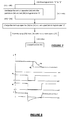
Figure 7 is a flow chart illustrating steps of a start-up sequence according to embodiments of the invention; -
Figure 8 is a graph showing the current inside the coil of the DC/DC Buck converter ofFigure 6 , as a function of time during the start-up sequence shown inFigure 7 , specifically upon receipt of a start-up command on the fly; and -
Figure 9 is a graph showing the current inside the coil of the DC/DC Buck converter ofFigure 6 , as a function of time during a start-up sequence on the fly, specifically upon receipt of a start-up command on the fly. - Referring to
Figure 1 , a known DC/DC Buck converter 10 comprises aninductor coil 12 wired in series, and acapacitor 14 wired in parallel with anoutput 16 and aninput 18. Theinput 18 is essentially a switching mechanism 20 that delivers a pulsed input voltage. The pulsing of the input voltage is generated by a ramp generator that feeds into oneinput 24 of acomparator 26, with theother input 28 being connected to the output of asecond comparator 30. Thesecond comparator 30 is connected, at oneinput 32, to theoutput voltage 34 of theconverter 10, and at itsother input 36 to a voltage generator that is driven by acurrent source 37. Thecurrent source 37 is connected to aninput capacitor 38 to provide aninternal reference voltage 42. - As can be seen from
Figures 3 , the Buck converter'sinternal reference voltage 42 is generated as a ramp going from zero to a finite voltage 44. Theinternal reference voltage 42 is combined with afixed voltage value 46 in a combining circuit 48 (as shown inFigure 1 ) to generate anoutput reference voltage 50 as follows: - At the beginning of the start-up phase 52, the
output reference voltage 50 is given byinternal reference voltage 42. As soon as theinternal reference voltage 42 reaches thefixed voltage value 46, theoutput reference voltage 50 is equal to thefixed voltage value 46. A such, during the start-up phase, the reference voltage seen internally, that is to say, theinternal reference voltage 50, is aramp 54 starting from zero volts with a fixed slope until it equals thefixed voltage value 46. - Referring now to the lower portion of
Figure 3 , during theoutput capacitor 24 loading phase 58, the output current 56 is sunk 60 by the power stage and thus the current inside thecoil 12 of theBuck converter 10 is dependent on theramp slope 54, and is given by the product of the capacitor'svalue 14 and theslope 54. - As shown by the curves of
Figure 3 , the current 56 inside thecoil 12 and thus the current output from the power stage, does not have a deep current inversion during the start-up phase 58. Hence, there is only little, if no power stage overstress. - Unfortunately this is not true when the
Buck converter 10 is restarted: theoutput voltage 34 is not around zero because theoutput capacitor 14 is not fully discharged when this happens, and so theBuck converter 10 massively discharges theoutput capacitor 14 in order to force theoutput voltage 34 around zero. - As shown by the curves in
Figure 4 , there is therefore a deepcurrent inversion 62 inside thecoil 12 during a restart because theoutput voltage 34 is first forced to zerovolts 64 before the start-up phase 54 is activated. Thecurrent inversion 62 inside thecoil 14 over-stresses the power stage and can lead to its destruction. Consequently, it is not possible to perform a start-up on the fly. - It is therefore known to "soft restart" a
Buck converter 10 using a pull-down resistor to discharge theoutput capacitor 14 to zero each time theBuck converter 10 is turned off. As shown inFigure 5 , an application is usually used to cause a device connected to the output of theBuck converter 10 to wait for a pre-specified turn-off time, which is typically 1 ms, to enable theoutput capacitor 14 to discharge sufficiently before theBuck converter 10 can be restarted safely by a trigger or "on" signal 68. - As shown in the lower portion of
Figure 5 , is when theoutput capacitor 14 is allowed to discharge, there is no deep inversion inside thecoil 12 and the power stage, and thus no overstress is created 70, in other words, the current inversion 70 falls within pre-specifiedtolerances 72. - The use of a "soft restart" such as that described above, however, is not always possible, especially in the case of Power Management Units (PMUs) such as those used in ICs for wireless devices such as mobile terminal systems, digital media players or the like, where application software requests can be asynchronous. In existing Buck
converter designs 10, what happens is that re-starting the Buckconverter 10 on the fly without theoutput capacitor 14 being completely discharged can lead to apower stage overstress 62 and possibly to an IC burnout. - An embodiment of the invention is shown in
Figure 6 , which comprises a DC/DC Buck converter 10 as described previously, but with the addition of a start-up controller 80 at the Buck converter's input. The start-up controller 80 solves the problem of deep current inversion in the Buck converter'soutput capacitor 14, which modifies the start-up phase and safely turns on theBuck converter 10, even if it is enabled asynchronously. The start-up controller 80 improves the design performance such that theBuck converter 10 can be re-restarted on the fly from any output voltage value, and from anyoutput capacitor 14 state. - The start-up controller comprises a
comparator 82 that compares theoutput voltage value 34 to the fixedreference voltage 46 and operates in two different ways: - In the first case, where the
output voltage 34 is higher than the fixedvoltage value 46, when aBuck converter 10 start-up request occurs, that is to say, when an "on"signal 68 goes fromlogical state 0 tological state 1 again, then the system discharges the output capacitor through a pull-downunit 84. The triggering of the pull-downunit 84 is effected via abridge circuit 86 and a logical ANDgate 88, whose output is only "on", when theoutput voltage 34 is greater than the fixedreference voltage 46, and when theBuck converter 10 start-uprequest signal 68 is in logical state "1". In such a situation, the start-up controller will recognise that theoutput capacitor 14 is not sufficiently discharged and that there is consequently a risk of a deepcurrent inversion 62 in the Buck converter's 10 output. As such, theoutput capacitor 14 is discharged through the pull-downunit 84 until theoutput voltage 34 has dropped below a pre-specified value determined by the parameters of thecomparator 82, at which point one of the inputs at the ANDgate 88 will be flipped, thus disconnecting the pull-downunit 84 and allowing theBuck converter 10 to re-start normally. - It will be noted from
Figure 6 , that during the pull-down phase, theBuck converter 10 is kept off. Then, as soon as theoutput voltage 34 reaches theinternal reference 46, the system begins to load theramp capacitor 38 to theoutput voltage value 34 thus enabling theBuck converter 10 to start, that is to say, the start-up request or "on"signal 68 goes from logical state "0" to logical state "1", and so the ramp starts from theoutput voltage value 34 with a fixed slope to reach the fixedvoltage value 46. - By doing this, the system avoids the need to fully discharge the
output capacitor 14 before starting theBuck converter 10 again, which can be done by changing the state of aninternal control signal 68 from logical state "0" to logical state "1". Instead, the system adds to the charge that was present inside theramp capacitor 38 before occurrence of thestart request 68 to a charge necessary for theoutput voltage 34 to reach the fixedvoltage value 46. - In the second case, where the
output voltage 34 is less than the fixedvoltage value 46 when a buck start-up request occurs, that is to say whensignal 68 goes from logical state "0" to logical state "1" again, then the system loads theramp capacitor 38 to theoutput voltage value 34 and then enables theBuck converter 10 to start. Thus, the system avoids the need to fully discharge theoutput capacitor 14 before starting theBuck converter 10 again and adds to the charge that was present inside theramp capacitor 38 before the start request occurred. - In both cases, because there is no deep discharge of the
output capacitor 14 during the start-up phase, the current driven through the power stage during the start-up sequence is not huge. It is consequently possible to safely execute a start-up on the fly, that is to say, restart theBuck converter 10, without having to wait forturnoff time 66 to elapse. It is also notable that theoutput voltage 34 never reaches zero during each re-start. - A typical start-up sequence according to the invention is shown in the flow chart of
Figure 7 and by the voltage and current curved ofFigures 8 and9 the two cases described above, respectively. - Referring to
Figure 7 , theBuck converter 10 is disabled, for instance by the de-asserting of acontrol signal 68 from logical value "0" to logical value "1". At the same time, an internal control signal 90 is de-asserted from logical state "1" to "0". In the first case, as shown inFigure 8 , theoutput voltage 34 is greater than the fixedvoltage value 46 when the Buck start-up request occurs, namely whensignal 68 is asserted to logical value "1" again. - In the case, as shown in
Figure 9 , theoutput voltage 34 is less than the fixedvoltage value 46, when the Buck start-up request occurs. - The advantages of the invention include: enabling any Buck converter start-up on the fly; reducing start-up time because there is no forced "off"
time 66 for allowing theoutput capacitor 14 to discharge; and theoutput voltage 34 does not fall to zero during start-up. - The present invention can also be implemented in software, say, as part of a computer program product, which comprises all the features enabling the implementation of the methods described herein, and which, when loaded in an information processing system, is able to carry out the method of the invention. Where a computer program is used or implied herein, it can mean any expression, in any language, code or notation, of a set of instructions intended to cause a system having an information processing capability to perform a particular function either directly or after conversion to another language. Such a computer program can be stored on a computer or machine readable medium allowing data, instructions, messages or message packets, and other machine readable information to be read from the medium. The computer or machine readable medium may include non-volatile memory, such as ROM, Flash memory, Disk drive memory, CD-ROM, and other permanent storage.
- Additionally, a computer or machine readable medium may include, for example, volatile storage such as RAM, buffers, cache memory, and network circuits. Furthermore, the computer or machine readable medium may comprise computer or machine readable information in a transitory state medium such as a network link and/or a network interface, including a wired network or a wireless network, that allow a device to read such computer or machine readable information.
- Expressions such as "comprise", "include", "incorporate", "contain", "is" and "have" are to be construed in a non-exclusive manner when interpreting the description and its associated claims, namely construed to allow for other items or components which are not explicitly defined also to be present. Reference to the singular is also to be construed in be a reference to the plural and vice versa.
- While there has been illustrated and described what are presently considered to be the preferred embodiments of the present invention, it will be understood by those skilled in the art that various other modifications may be made, and equivalents may be substituted, without departing from the true scope of the present invention. Additionally, many modifications may be made to adapt a particular situation to the teachings of the present invention without departing from the central inventive concept described herein. Furthermore, an embodiment of the present invention may not include all of the features described above.
- Therefore, it is intended that the present invention not be limited to the particular embodiments disclosed, but that the invention include all embodiments falling within the scope of the invention as broadly defined above.
- A person skilled in the art will readily appreciate that various parameters disclosed in the description may be modified and that various embodiments disclosed and/or claimed may be combined without departing from the scope of the invention.
Claims (11)
- A method of controlling a start-up sequence of a DC/DC Buck converter, the method being characterised by the steps of:- continuously comparing the Buck converter's output voltage with an internal reference voltage and continuously monitoring for a Buck converter start-up signal, wherein if the output voltage is greater than the reference voltage when a Buck converter start-up signal is detected, switching off the Buck converter and discharging an output capacitor of the Buck converter through a pull-down unit until the output voltage substantially equals the internal reference voltage and then restarting the Buck converter.
- The method of claim 1, further comprising the step of keeping the Buck converter switched on when the output voltage is less than the reference voltage.
- A DC/DC Buck converter (10) comprising a start-up controller (80), characterised by: the start-up controller (80) comprising a comparator (82) operatively connected to, and adapted to compare a first voltage corresponding to an output voltage (34) of the Buck converter (10) a second voltage corresponding to an internal reference voltage (46), the output of the comparator (82) providing a first input for an AND logic controller (88) whose second input is operatively connected to a Buck converter start-up signal (68), wherein an output of the AND logic controller (88) is configured to switch off the Buck converter (10) and to discharge an output capacitor (14) of the Buck converter (10) via a pull-down circuit (84) when the AND logic controller's input are both in a logical state "1".
- The DC/DC Buck converter of claim 3, wherein the output of the comparator (82) connected to the first logical input of the AND logic controller (88) goes to logical state "0" when output voltage (34) of the Buck converter (10) falls below the internal reference voltage (46).
- The DC/DC Buck converter of claim 3 or claim 4, wherein the DC/DC Buck converter (10) comprises an inductor coil (12) wired in series, and a capacitor (14) wired in parallel with, an output (16) and an input (18), the input (18) comprising switching means (20) comprising a ramp generator (22) and a comparator (28) together being configured to deliver a pulsed input voltage from a voltage generator (30) that is driven by a current source (38).
- The DC/DC Buck converter of claim 5, wherein the current source (38) is connected to an input capacitor (40) to provide the internal reference voltage (42).
- The DC/DC Buck converter of any of claims 3 to 6, further comprising a combining circuit (48) for combining the internal reference voltage (42) with a fixed voltage value (46) to generate an output reference voltage (50).
- The DC/DC Buck converter of any of claims 3 to 7, wherein the start-up controller (80) comprises a bridge circuit (86) and a logical AND gate (88), whose output is only "on", when the output voltage (34) is greater than the fixed reference voltage (46), and when the Buck converter (10) start-up request signal (68) is in logical state "1".
- The DC/DC Buck converter of claim 8, wherein the Buck Converter's output capacitor (14) is discharged through the pull-down unit (84) until the output voltage (34) has dropped below a pre-specified value.
- The DC/DC Buck converter of claim 9, wherein the pre-specified value is determined by the parameters of the comparator (82).
- The DC/DC Buck converter of claim 8, claim 9 or claim 10, wherein during the pull-down phase, the Buck converter (10) is kept off, such that when the output voltage (34) reaches the internal reference voltage (46), the system (10) begins to load the ramp capacitor (38) to the output voltage value (34).The DC/DC Buck converter of any of claims 3 to 11, wherein where the output voltage (34) is less than the fixed voltage value (46) when a buck start-up request (68) goes from logical state "0" to logical state "1", the system loads the ramp capacitor (38) to the output voltage value 34 and then enables the Buck converter (10) to start.
Priority Applications (4)
| Application Number | Priority Date | Filing Date | Title |
|---|---|---|---|
| EP13162641.8A EP2722977A3 (en) | 2012-09-10 | 2013-04-06 | Method and apparatus for controlling a start-up sequence of a DC/DC Buck converter |
| US14/426,761 US9531254B2 (en) | 2012-09-10 | 2013-08-15 | Method and apparatus for controlling a start-up sequence of a DC/DC buck converter |
| CN201380055063.0A CN104737431B (en) | 2012-09-10 | 2013-08-15 | For the method and apparatus for the initiating sequence for controlling DC/DC buck converters |
| PCT/EP2013/067070 WO2014037204A1 (en) | 2012-09-10 | 2013-08-15 | Method and apparatus for controlling a start-up sequence of a dc/dc buck converter |
Applications Claiming Priority (2)
| Application Number | Priority Date | Filing Date | Title |
|---|---|---|---|
| EP12306089 | 2012-09-10 | ||
| EP13162641.8A EP2722977A3 (en) | 2012-09-10 | 2013-04-06 | Method and apparatus for controlling a start-up sequence of a DC/DC Buck converter |
Publications (2)
| Publication Number | Publication Date |
|---|---|
| EP2722977A2 true EP2722977A2 (en) | 2014-04-23 |
| EP2722977A3 EP2722977A3 (en) | 2018-01-03 |
Family
ID=48044693
Family Applications (1)
| Application Number | Title | Priority Date | Filing Date |
|---|---|---|---|
| EP13162641.8A Withdrawn EP2722977A3 (en) | 2012-09-10 | 2013-04-06 | Method and apparatus for controlling a start-up sequence of a DC/DC Buck converter |
Country Status (3)
| Country | Link |
|---|---|
| US (1) | US9531254B2 (en) |
| EP (1) | EP2722977A3 (en) |
| CN (1) | CN104737431B (en) |
Cited By (1)
| Publication number | Priority date | Publication date | Assignee | Title |
|---|---|---|---|---|
| CN104767373A (en) * | 2015-04-27 | 2015-07-08 | 海南汉地阳光石油化工有限公司 | Frequency converter low voltage self-starting control method and system |
Families Citing this family (3)
| Publication number | Priority date | Publication date | Assignee | Title |
|---|---|---|---|---|
| CN104133167A (en) * | 2013-04-30 | 2014-11-05 | 鸿富锦精密工业(深圳)有限公司 | DC step-down circuit test system and method |
| US10193457B1 (en) | 2017-09-15 | 2019-01-29 | Abb Schweiz Ag | System and method for starting up a high density isolated DC-to-DC power converter |
| US10965212B2 (en) | 2018-04-17 | 2021-03-30 | STMicroelectronics (Alps) SAS | Switched-mode power supply with bypass mode |
Family Cites Families (22)
| Publication number | Priority date | Publication date | Assignee | Title |
|---|---|---|---|---|
| JPH01148064A (en) * | 1987-12-04 | 1989-06-09 | Victor Co Of Japan Ltd | Protection circuit for power source |
| JPH0622544A (en) * | 1992-06-30 | 1994-01-28 | Ricoh Co Ltd | Switching regulator |
| EP1376838A1 (en) * | 2002-06-17 | 2004-01-02 | Magnetek S.p.A. | Current-powered converter with energy recovery clamping circuit |
| JP2004336972A (en) | 2003-05-12 | 2004-11-25 | Internatl Business Mach Corp <Ibm> | Power supply and power supply control device |
| US7038514B2 (en) * | 2003-10-28 | 2006-05-02 | Intersil Americas Inc. | Startup circuit for a DC-DC converter |
| TW200713761A (en) | 2005-09-21 | 2007-04-01 | Richtek Techohnology Corp | Circuit and method for a soft-start with residual voltage |
| US7755419B2 (en) * | 2006-01-17 | 2010-07-13 | Cypress Semiconductor Corporation | Low power beta multiplier start-up circuit and method |
| US7816896B2 (en) * | 2006-10-25 | 2010-10-19 | 02Micro International Limited | Circuits and methods for controlling a converter |
| JP5015035B2 (en) | 2008-02-27 | 2012-08-29 | 株式会社リコー | Step-down switching regulator |
| CN201163748Y (en) * | 2008-03-12 | 2008-12-10 | 纬创资通股份有限公司 | Electronic device capable of improving power supply stability during starting and shutdown and related power supply control device thereof |
| WO2010003785A2 (en) * | 2008-07-11 | 2010-01-14 | Em Microelectronic-Marin Sa | Power supply unit having a voltage converter |
| JP5317188B2 (en) * | 2009-02-20 | 2013-10-16 | 株式会社安川電機 | Inverter device for electric vehicle and protection method thereof |
| US8416584B2 (en) * | 2009-10-30 | 2013-04-09 | Intersil Americas Inc. | Power supply with low power consumption hiccup standby operation |
| US8378655B2 (en) | 2009-11-10 | 2013-02-19 | Maxim Integrated Products, Inc. | Determining initial pre-bias in a switch-mode controller for a buck converter device |
| TWI441405B (en) * | 2011-01-19 | 2014-06-11 | Hon Hai Prec Ind Co Ltd | Driving circuit |
| US8890501B2 (en) | 2011-02-11 | 2014-11-18 | Intersil Americas, Llc | System and method for soft-starting a power converter with a pre-charged output |
| CN102751872B (en) * | 2011-04-21 | 2016-04-06 | 登丰微电子股份有限公司 | feedback control circuit |
| DE202011106116U1 (en) * | 2011-09-26 | 2011-11-08 | Dillex Immobilien Gmbh | Boost converter circuit |
| WO2013079111A1 (en) * | 2011-12-01 | 2013-06-06 | Telefonaktiebolaget L M Ericsson (Publ) | Start-up procedure for an isolated switched mode power supply |
| CN102545193B (en) * | 2011-12-29 | 2014-07-23 | 深圳市合信自动化技术有限公司 | Method and device for discharging residual voltage of bus of servo controller |
| US9281741B2 (en) * | 2013-03-12 | 2016-03-08 | Taiwan Semiconductor Manufacturing Company Limited | Start-up circuit for voltage regulation circuit |
| US9509210B2 (en) * | 2013-07-17 | 2016-11-29 | Taiwan Semiconductor Manufacturing Company, Ltd. | Start-up circuit and method for AC-DC converters |
-
2013
- 2013-04-06 EP EP13162641.8A patent/EP2722977A3/en not_active Withdrawn
- 2013-08-15 US US14/426,761 patent/US9531254B2/en active Active
- 2013-08-15 CN CN201380055063.0A patent/CN104737431B/en active Active
Non-Patent Citations (1)
| Title |
|---|
| None |
Cited By (1)
| Publication number | Priority date | Publication date | Assignee | Title |
|---|---|---|---|---|
| CN104767373A (en) * | 2015-04-27 | 2015-07-08 | 海南汉地阳光石油化工有限公司 | Frequency converter low voltage self-starting control method and system |
Also Published As
| Publication number | Publication date |
|---|---|
| CN104737431A (en) | 2015-06-24 |
| US9531254B2 (en) | 2016-12-27 |
| CN104737431B (en) | 2018-01-26 |
| EP2722977A3 (en) | 2018-01-03 |
| US20150249382A1 (en) | 2015-09-03 |
Similar Documents
| Publication | Publication Date | Title |
|---|---|---|
| KR20150075034A (en) | Switching regulator and electronic apparatus | |
| US9531254B2 (en) | Method and apparatus for controlling a start-up sequence of a DC/DC buck converter | |
| TW200934037A (en) | Adaptive current limiting for any power source with output equivalent series resistance | |
| JPWO2016135815A1 (en) | Load drive circuit and load short circuit detection circuit | |
| US11139814B2 (en) | Power switch circuit | |
| CN112154598B (en) | Power conversion device | |
| US9397493B2 (en) | Switching device | |
| JP2014027707A (en) | Electrical apparatus | |
| KR100647746B1 (en) | Apparatus and method for cpu surge reduction and protection | |
| JP4890014B2 (en) | Switching regulator and switching regulator control circuit | |
| WO2014037204A1 (en) | Method and apparatus for controlling a start-up sequence of a dc/dc buck converter | |
| WO2015118636A1 (en) | Discharging device | |
| CN107294386A (en) | DC power control circuit | |
| JP5750326B2 (en) | Electronic device protection circuit | |
| JP2019503157A (en) | Brushless DC motor protection circuit and control device | |
| US10068721B2 (en) | Hot swap circuit | |
| EP3496255A1 (en) | A power converter for delaying entering burst mode and method thereof | |
| JP6183395B2 (en) | Power supply control system and power supply control method | |
| CN102906664A (en) | A device that provides auxiliary power to parts of the device on a current-limited power bus | |
| CN113765168B (en) | Charging circuit, charging circuit control method and electronic device | |
| JP2001339940A (en) | Power supply with power switch means | |
| JP2007028745A (en) | Rechargeable battery charging method | |
| EP2717446A1 (en) | Powering down switching regulator using a ramped reference voltage | |
| CN118174703A (en) | Soft start switch circuit | |
| CN110535382B (en) | Synchronous rectifier generator and energy distribution method thereof |
Legal Events
| Date | Code | Title | Description |
|---|---|---|---|
| PUAI | Public reference made under article 153(3) epc to a published international application that has entered the european phase |
Free format text: ORIGINAL CODE: 0009012 |
|
| AK | Designated contracting states |
Kind code of ref document: A2 Designated state(s): AL AT BE BG CH CY CZ DE DK EE ES FI FR GB GR HR HU IE IS IT LI LT LU LV MC MK MT NL NO PL PT RO RS SE SI SK SM TR |
|
| AX | Request for extension of the european patent |
Extension state: BA ME |
|
| 17P | Request for examination filed |
Effective date: 20141002 |
|
| RBV | Designated contracting states (corrected) |
Designated state(s): AL AT BE BG CH CY CZ DE DK EE ES FI FR GB GR HR HU IE IS IT LI LT LU LV MC MK MT NL NO PL PT RO RS SE SI SK SM TR |
|
| RAP1 | Party data changed (applicant data changed or rights of an application transferred) |
Owner name: OCT CIRCUIT TECHNOLOGIES INTERNATIONAL LIMITED |
|
| PUAL | Search report despatched |
Free format text: ORIGINAL CODE: 0009013 |
|
| AK | Designated contracting states |
Kind code of ref document: A3 Designated state(s): AL AT BE BG CH CY CZ DE DK EE ES FI FR GB GR HR HU IE IS IT LI LT LU LV MC MK MT NL NO PL PT RO RS SE SI SK SM TR |
|
| AX | Request for extension of the european patent |
Extension state: BA ME |
|
| RIC1 | Information provided on ipc code assigned before grant |
Ipc: H02M 3/158 20060101ALI20171127BHEP Ipc: H02M 1/36 20070101AFI20171127BHEP |
|
| STAA | Information on the status of an ep patent application or granted ep patent |
Free format text: STATUS: THE APPLICATION IS DEEMED TO BE WITHDRAWN |
|
| 18D | Application deemed to be withdrawn |
Effective date: 20180704 |