EP2722971A2 - Motor and washing maching having the same - Google Patents
Motor and washing maching having the same Download PDFInfo
- Publication number
- EP2722971A2 EP2722971A2 EP13188385.2A EP13188385A EP2722971A2 EP 2722971 A2 EP2722971 A2 EP 2722971A2 EP 13188385 A EP13188385 A EP 13188385A EP 2722971 A2 EP2722971 A2 EP 2722971A2
- Authority
- EP
- European Patent Office
- Prior art keywords
- rotor
- magnets
- moulding
- magnetizing
- disposed
- Prior art date
- Legal status (The legal status is an assumption and is not a legal conclusion. Google has not performed a legal analysis and makes no representation as to the accuracy of the status listed.)
- Withdrawn
Links
Images









Classifications
-
- D—TEXTILES; PAPER
- D06—TREATMENT OF TEXTILES OR THE LIKE; LAUNDERING; FLEXIBLE MATERIALS NOT OTHERWISE PROVIDED FOR
- D06F—LAUNDERING, DRYING, IRONING, PRESSING OR FOLDING TEXTILE ARTICLES
- D06F37/00—Details specific to washing machines covered by groups D06F21/00 - D06F25/00
- D06F37/20—Mountings, e.g. resilient mountings, for the rotary receptacle, motor, tub or casing; Preventing or damping vibrations
-
- H—ELECTRICITY
- H02—GENERATION; CONVERSION OR DISTRIBUTION OF ELECTRIC POWER
- H02K—DYNAMO-ELECTRIC MACHINES
- H02K1/00—Details of the magnetic circuit
- H02K1/06—Details of the magnetic circuit characterised by the shape, form or construction
- H02K1/22—Rotating parts of the magnetic circuit
- H02K1/27—Rotor cores with permanent magnets
- H02K1/2706—Inner rotors
- H02K1/272—Inner rotors the magnetisation axis of the magnets being perpendicular to the rotor axis
- H02K1/274—Inner rotors the magnetisation axis of the magnets being perpendicular to the rotor axis the rotor consisting of two or more circumferentially positioned magnets
- H02K1/2753—Inner rotors the magnetisation axis of the magnets being perpendicular to the rotor axis the rotor consisting of two or more circumferentially positioned magnets the rotor consisting of magnets or groups of magnets arranged with alternating polarity
- H02K1/276—Magnets embedded in the magnetic core, e.g. interior permanent magnets [IPM]
- H02K1/2766—Magnets embedded in the magnetic core, e.g. interior permanent magnets [IPM] having a flux concentration effect
- H02K1/2773—Magnets embedded in the magnetic core, e.g. interior permanent magnets [IPM] having a flux concentration effect consisting of tangentially magnetized radial magnets
-
- H—ELECTRICITY
- H02—GENERATION; CONVERSION OR DISTRIBUTION OF ELECTRIC POWER
- H02K—DYNAMO-ELECTRIC MACHINES
- H02K15/00—Processes or apparatus specially adapted for manufacturing, assembling, maintaining or repairing of dynamo-electric machines
- H02K15/02—Processes or apparatus specially adapted for manufacturing, assembling, maintaining or repairing of dynamo-electric machines of stator or rotor bodies
- H02K15/03—Processes or apparatus specially adapted for manufacturing, assembling, maintaining or repairing of dynamo-electric machines of stator or rotor bodies having permanent magnets
-
- H—ELECTRICITY
- H02—GENERATION; CONVERSION OR DISTRIBUTION OF ELECTRIC POWER
- H02K—DYNAMO-ELECTRIC MACHINES
- H02K16/00—Machines with more than one rotor or stator
- H02K16/02—Machines with one stator and two or more rotors
-
- H—ELECTRICITY
- H02—GENERATION; CONVERSION OR DISTRIBUTION OF ELECTRIC POWER
- H02K—DYNAMO-ELECTRIC MACHINES
- H02K2213/00—Specific aspects, not otherwise provided for and not covered by codes H02K2201/00 - H02K2211/00
- H02K2213/03—Machines characterised by numerical values, ranges, mathematical expressions or similar information
Definitions
- the present invention relates to a motor and a washing machine having the same.
- a washing machine which washes clothes using electricity, generally includes a tub to retain wash water, a drum rotatably installed in the tub and a motor to rotate the drum.
- the motor which produces rotating power from electric energy, is provided with a stator and a rotor.
- the rotor is configured to electromagnetically interact with the stator, and is rotated by force acting between a magnetic field and current flowing through a coil.
- a magnetic flux concentrated-type motor includes a stator, a rotor disposed at the inside or outside of the stator to rotate by interacting with the stator and provided with segmented rotor cores disposed in the circumferential direction of the rotor and permanent magnets (hereinafter, referred to as "magnets") respectively coupled between the rotor cores.
- the magnets are coupled between the rotor cores by magnetizing the magnets and then coupling the magnetized magnets between the rotor cores (hereinafter, referred to as "pre-magnetization technique”) or by coupling the magnets between the rotor cores and then magnetizing the magnets (hereinafter, referred to as "post-magnetization technique").
- pre-magnetization technique magnetizing the magnets and then coupling the magnetized magnets between the rotor cores
- post-magnetization technique When the pre-magnetization technique is used, magnetization of the magnets is easily implemented, but attractive force or repulsive force acing between the magnets may make it difficult to couple the magnets between the rotor cores and even cause damage to surrounding devices. For this reason, the post-magnetization technique has often been used in recent years.
- a motor includes a stator, and a rotor rotatably disposed at an inside or outside of the stator, wherein the rotor includes a plurality of rotor cores radially disposed, a plurality of magnets respectively disposed between the rotor cores, a moulding to support the rotor cores and the magnets and define an accommodation space to accommodate an inner magnetizing yoke to magnetize the magnets, and a gap maintaining portion formed at at least one section of an inner circumferential surface of the moulding in order to maintain a gap between an outer circumferential surface of the inner magnetization yoke and inner circumferential surfaces of the rotor cores between about 2 mm and about 5 mm when the inner magnetization yoke is accommodated in the accommodation space to magnetize the magnets.
- the gap maintaining portion may be substantially parallel with a direction in which a rotational axis of the rotor extends.
- a length of the gap maintaining portion formed in an axial direction of the rotor may be equal to or greater than a length of the magnets.
- a gap between one surface of the inner magnetizing yoke adjacent to a bottom surface of the moulding and one surface of the magnets adjacent to the bottom surface of the moulding may be smaller than 1/10 a length of the magnets.
- the inner circumferential surface of the moulding may be substantially perpendicular to a bottom surface of the moulding.
- a gap between an outer magnetizing yoke disposed at an outside of the rotor to magnetize the magnets together with the inner magnetizing yoke and outer circumferential surfaces of the rotor cores may be between about 0.2 mm and about 0.5 mm.
- the rotor may include at least one first reinforcing rib formed on a bottom surface of the moulding to reinforce the rotor, and at least one second reinforcing rib formed on an outer surface of the moulding opposite to the bottom surface of the moulding to reinforce the rotor, wherein a length of the second reinforcing rib in a direction in which a radius of the rotor increases may be greater than a length of the first reinforcing rib.
- the first reinforcing rib and the second reinforcing rib may be radially disposed with respect to a center of rotation of the rotor.
- the magnets may include a first magnet and a second magnet forming magnetic fluxes in opposite directions toward one of the rotor cores disposed therebetween.
- the magnetic fluxes from the first magnet and the second magnet may be introduced into the one of the rotor cores disposed between the first magnet and the second magnet, combined, and discharged toward the stator.
- a washing machine includes a body, a tub disposed in the body, a drum rotatably disposed in the tub, and a motor including a stator fixed to a rear surface of the tub and a rotor rotatably disposed inside the stator, wherein the rotor includes a plurality of magnets arranged in a circumferential direction of the rotor, a plurality of rotor cores alternated with the magnets in the circumferential direction of the rotor, magnetic fluxes formed at the magnets being concentrated at the rotor cores, and a moulding to support the rotor cores and the magnets and define an accommodation space to accommodate an inner magnetizing yoke to magnetize the magnets, wherein, when the inner magnetization yoke is accommodated in the accommodation space, a gap between one surface of the inner magnetizing yoke adjacent to a bottom surface of the moulding and one surface of the magnets adjacent to the bottom surface of the moulding is smaller
- an outer circumferential surface of the inner magnetizing yoke may be disposed parallel with an inner circumferential surface of the moulding.
- a gap between an outer circumferential surface of the inner magnetizing yoke and an inner circumferential surface of the moulding may be between about 0.5 mm and about 3 mm.
- An inner circumferential surface of the moulding may be substantially perpendicular to the bottom surface of the moulding.
- washing machine with a motor, which is applicable to all kinds of apparatuses including an air conditioner, an electric vehicle, a light rail transit system, an electric bicycle and a small generator that employ a motor as a power source.
- a washing machine will be described as an example of application of the motor.
- FIG. 1 is a view illustrating a washing machine according to an exemplary embodiment of the present disclosure.
- the washing machine 1 includes a cabinet 10 forming the external appearance of the washing machine 1, a tub 20 disposed within the cabinet 10, a drum 30 rotatably disposed in the tub 20, and a motor 40 to rotate the drum 30.
- the front portion of the cabinet 10 is provided with an inlet 11 through which laundry may be inserted into the drum 30.
- the inlet 11 is opened and closed by a door 12 installed at the front of the cabinet 10.
- a water supply pipe 50 to supply wash water to the tub 20 is installed at an upper portion of the tub 20.
- One side of the water supply pipe 50 is connected to an external water supply source (not shown), and the other side of the water supply pipe 50 is connected to a detergent supply unit 60.
- the detergent supply unit 60 is connected to the tub 20 through a connection pipe 55. Water flowing into the water supply pipe 50 is supplied to the tub 20 along with a detergent via the detergent supply unit 60.
- a drain pump 70 and drain pipe 75 Installed at the bottom of the tub 20 are a drain pump 70 and drain pipe 75 to discharge water in the tub 20 from the cabinet 10.
- a plurality of through holes 31 is formed around the drum 30 to allow flow of wash water therethrough, and a plurality of lifters 32 is installed on the inner circumferential surface of the drum 30 to allow the laundry to tumble during rotation of the drum 30.
- the drum 30 and motor 40 are connected to each other through a drive shaft 80.
- the drive shaft 80 transmits the rotating power of the motor 40 to the drum 30.
- One end of the drive shaft 80 is connected to the drum 30, and the other end of the drive shaft 80 extends to the outside of the rear wall 21 of the tub 20.
- the bearing housing 82 Installed at the rear wall 21 of the tub 20 is a bearing housing 82 by which the drive shaft 80 is rotatably supported.
- the bearing housing 82 may be formed of an aluminum alloy, and may be inserted into the rear wall 21 of the tub 20 when the tub 20 is manufactured through injection moulding.
- Bearings 84 are installed between the bearing housing 82 and the drive shaft 80 to allow smooth rotation of the drive shaft 80.
- FIG. 2 is a view illustrating a tub and a stator and rotor of a motor of the washing machine according to the exemplary embodiment of the present disclosure, in which the tub, stator and rotor are separated from each other, and FIG. 3 is a perspective view of the stator of FIG. 2 .
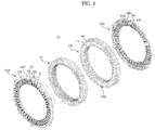
- FIG. 4 is an exploded perspective view illustrating constituents of the stator of FIG. 3 , which are separated from each other, and FIG. 5 is an exploded perspective view of FIG. 4 taken at a different angle.
- FIG. 6 is an enlarged view of section 'A' of FIG. 4
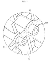
- FIG. 7 is an enlarged view of section 'B' of FIG. 2 .
- the coil is shown in FIGS. 4 and 5 .
- the motor 40 is coupled to the outside of the tub 20 to drive the drum 30 in opposite directions.
- the motor 40 includes a stator 100 mounted to the rear wall 20 of the tub 20, and a rotor 200 disposed around the stator 100 to rotate through electromagnetic interaction with the stator 100.
- the stator 100 includes a stator core 110 formed of a metal material, a first insulator 120a and a second insulator 120b covering both ends 110a and 110b of the stator core 110, an insulation film 130 inserted between the first insulator 120a and the second insulator 120b, and a coil 140 wound around the first insulator 120a, the second insulator 120b and the insulation film 130.
- the stator core 110 may be formed by stacking metal plates processed through press working.
- the first insulator 120a, second insulator 120b and insulation film 130 may be formed of electrical insulators.
- the stator core 110 includes a ring-shaped core body 112, and a plurality of core teeth 114 extending inward from the inner circumferential surface of the core body 112 in the radial direction of the core body 112 and arranged spaced apart from each other along the inner circumferential surface of the core body 112.
- the first insulator 120a includes a first insulator body 122a having a shape corresponding to that of the core body 112, and a plurality of first insulator teeth 124a having a shape corresponding that of the core teeth 114.
- the first insulator teeth 124a extend inward in the radial direction of the first insulator body 122a and are arranged spaced apart from each other along the inner circumferential surface of the first insulator body 122a.
- the first insulator 120a further includes a plurality of connection ribs 126 connected to the second insulator 120b, and first through holes 128 to fix the tub 20 to the rear wall 21 therethrough.
- the connection ribs 126 protrude from the first insulator body 122a toward the second insulator 120b, and are arranged spaced a predetermined distance apart from each other in the circumferential direction of the first insulator body 122a and adapted to be connected to the second insulator 120b when the stator core 110, first insulator 120a and second insulator 120b are coupled to each other.
- the first through holes 128 are formed through the first insulator body 122a and the connection rib 126.
- Sleeves 170 may be inserted into the first through holes 128 to reinforce fastening of the stator 100 to the tub 20.
- connection rib 126 protruding from the first insulator 120a may vary depending on the stack height of the stator core 110. That is, if the stack of the stator core 110 is high, the connection rib 126 may be formed to have a long protruding length. If the stack of stator core 110 is short, the connection rib 126 may be formed to have a short protruding length. In case that the connection ribs 126 and the first insulator 120a are integrally formed through injection moulding, a mould for injection moulding of the first insulator 120a does not need to be separately fabricated whenever the length of the connection ribs 126 changes according to change in the stack height of the stator core 110, but one mould may be used in common.
- connection ribs 126 may be adjusted during fabrication of the first insulator 120a through injection moulding by filling a portion of the mold for formation of the connection ribs 126, which is pre-formed to have a deep depth, to the height corresponding to the protruding length of the connection ribs 126, using a tool such as a jig.
- the second insulator 120b includes a second insulator body 122b having a shape corresponding to that of the core body 112, and a plurality of second insulator teeth 124b having a shape corresponding to that of the core teeth 114.
- the second insulator teeth 124b extend inward in the radial direction of the second insulator body 122b and are arranged spaced apart from each other along the inner circumferential surface of the second insulator body 122b.
- the second insulator 120b further includes a plurality of fixing ribs 127 connected to the tub 20, second through holes 129 formed through the second insulator body 122b and the fixing rib 127, and a plurality of fixing pins 123 protruding from surfaces of the fixing ribs 127 facing the rear wall 21 of the tub 20 toward the rear wall 21 of the tub 20.
- the fixing ribs 127 protrude from the second insulator body 122b toward the rear wall 21 of the tub 20, and are arranged spaced a predetermined distance apart from each other in the circumferential direction of the second insulator body 122b. The fixing ribs 127 contact the rear wall 21 of the tub 20 when the stator 110 is coupled to the tub 20.
- the fixing pins 123 are adapted to determine the position of the stator 100 before being inserted into the rear wall 21 of the tub 20 to fix the stator 100 to the rear wall 21 of the tub 20.
- the second through holes 129 are formed through the second insulator body 122b and the fixing ribs 127, and are disposed to be concentric with the first through holes 128. Sleeves 170 may be inserted into the second through holes 129 to reinforce fastening of the stator 100 to the tub 20.
- First accommodation holes 161 to accommodate the fixing pins 123 inserted thereinto are provided at the rear wall 21 of the tub 20 to which the stator 100 is mounted.
- the bearing housing 82 inserted into the rear wall 21 of the tub 20 is provided with second accommodation holes 162 to accommodate fixing members 150 inserted thereinto.
- At least two first accommodation holes 161 and at least two second accommodation holes 162 are arranged spaced apart from each other in the circumferential direction of the tub 20.
- the first accommodation holes 161 allow the position of the stator 100 to be determined before the fixing pins 142 are accommodated therein to fix the stator 100 to the rear wall 21 of the tub 20, while the second accommodation holes 162 accommodate the fixing members 150 penetrating the sleeves 170, thereby allowing the stator 100 to be fixed to the rear wall 21 of the tub 20.
- the bearing housing 82 is inserted into the rear wall 21 of the tub 20 to reinforce the tub 20, and directly coupled to the stator 100 through the second accommodation holes 162 to allow the stator 100 to be stably fixed to the rear wall 21 of the tub 20.
- first accommodation holes 161 and the second accommodation holes 162 may be provided in the bearing housing 82.
- the insulation film 130 is inserted between the first insulator 120a and the second insulator 120b.
- the insulation film 130 is formed approximately in a bracket shape, and disposed between one of the first insulator teeth 124a and one of the second insulator teeth 124b neighboring each other to electrically insulate the stator core 110 and the coil 140.
- the insulation film 130 may be formed of paper or plastics which are electrically nonconductive.
- the coil 140 is wound around the first insulator 120a, second insulator 120b and insulation film 130.
- 3-phase alternating current (AC) power is supplied to the coil 140, magnetic flux is created at the stator core 110.
- the magnetic flux created at the stator core 110 interacts with the magnetic flux created at the rotor 200 to rotate the rotor 200.
- FIGS. 8 and 9 are perspective views of the rotor of FIG. 2
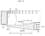
- FIG. 10 is a cross-sectional view taken along line I-I of FIG. 9
- FIG. 11 is a plan view illustrating the rotor cores and the magnets of the rotor of FIG. 2
- FIG. 12 is an enlarged view of section 'C' of FIG. 11
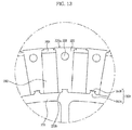
- FIG. 13 is a view illustrating coupling of a moulding to the rotor cores and the magnets shown in FIG. 12 .
- the rotor 200 includes a plurality of rotor cores 220 disposed in a radial shape, a plurality of magnets 240 respectively disposed between the rotor cores 220, and a moulding (body) 260 to support the rotor cores 220 and the magnets 240.
- the rotor cores 220 support the magnets 240, and form a magnetic path created at the magnets 240.
- the rotor cores 220 are arranged along the circumferential direction of the rotor 200, and respectively disposed spaced apart from each other between the rotor cores 220 to accommodate the magnets 240.
- Each of the rotor cores 220 includes an inner end 220b disposed adjacent to the center of the rotor 200, and an outer end 220a disposed adjacent to the core teeth 114 of the stator core 110 to define an air gap in cooperation with the core teeth 114.
- the width of each of the rotor cores 220 in a circumferential direction increases from the inner end 220b thereof to the outer end 220a thereof.
- the rotor cores 220 may be formed by stacking silicon steel plates processed through press working.
- each of the segmented rotor cores 220 includes a through hole 223 and a coupling groove 224.
- the through hole 223 and coupling groove 224 are coupled to the moulding 260 that supports the rotor cores 220.
- the through hole 223 is formed through the body of the rotor core 220 such that the moulding 260 is accommodated therein and coupled thereto during fabrication of the moulding 260 through injection moulding.
- the diameter of the through hole 223 may be between about 1.5 mm and about 5 mm. If the diameter of the through hole 223 is too small, the rotor cores 220 may not be securely supported by the moulding 260. If the diameter of the through hole 223 is too large, the magnetic flux concentrated at the rotor core 220 may interrupt creation of a magnetic path through the outer end 220a of the rotor core 220.
- a plurality of through holes 223 may be disposed in the radial direction of the rotor 200. If the number of the through holes 223 is too large, they may interrupt creation of a magnetic path through the outer end 220a of the rotor core 220 as in the case of the through hole 223 having too large a diameter, which may cause the magnetic flux concentrated at the rotor core 220 to interrupt creation of the magnetic path through the outer end 220a of the rotor core 220. Therefore, the number may be equal to or less than three.
- the coupling groove 224 includes a first accommodation portion 224a formed approximately at the center of the inner end 220b of the rotor core 220 and having a width in a circumferential direction which decreases as the first accommodation portion 224a extends from the inner end 220b toward the outer end 220a, and a second accommodation portion 224b connected with the first accommodation portion 224a, and having a width which increases as the second accommodation portion 224b extends from the inner end 220b toward the outer end 220a.
- the first accommodation portion 224a and the second accommodation portion 224b accommodate the moulding 260 when the moulding 260 is fabricated through injection moulding such the rotor core 220 and the moulding 260 are securely coupled to each other.
- the magnets 240 are arranged along the circumferential direction of the rotor 200 to be radially positioned with respect to the center of the rotor 200.
- the magnet 240 may be a magnet containing a rare-earth element such as neodymium and samarium or a ferrite magnet which may semi-permanently maintain the magnetic property of high energy density.
- the magnetic fluxes created at the magnets 240 are arranged along the circumferential direction of the rotor 200. Any two neighboring ones of the magnets 240 are disposed such that the portions thereof having the same polarity face each other. If a magnetic circuit is formed in this way, the magnetic flux generated by the magnets 240 is concentrated, and therefore it may be possible to reduce the size of the motor 40 while improving the performance thereof.
- the moulding 260 includes a serration 262 coupled to the drive shaft 80, heat dissipation outlets 264 to dissipate heat generated during rotation of the rotor 200, and a plurality of reinforcing ribs 269.
- the serration 262 includes a shaft hole 262a into which the drive shaft 80 is inserted to be coupled thereto.
- the serration 262 may be formed of a metal material such that the drive shaft 80 is firmly coupled thereto, and may be inserted into a mold for fabrication of the moulding 260 during formation of the moulding 260 through injection moulding.
- the reinforcing ribs 269 include at least one first reinforcing rib 269a radially formed on the bottom surface 260a of the moulding 260 around a shaft hole 262a to reinforce the rotor 200, and at least one second reinforcing rib 269b radially formed on the outer surface 260b of the moulding 260 opposite to the bottom surface 260a of the moulding 260 around the shaft hole 262a to reinforce the rotor 200.
- the portions of the first reinforcing rib 269 and the second reinforcing rib 269b to which the serration 262 is coupled are formed to be thick such that the serration 262 is firmly coupled to the moulding 260.
- the length L1 of the first reinforcing rib 269a is shorter than the length L2 of the second reinforcing rib 269b in the direction in which the radius of the rotor 200 increases. If the length L1 of the first reinforcing rib 269a is too long in the direction in which the radius of the rotor 200 increases, interference with the inner magnetizing yoke 320 to magnetize the magnets 240 may occur.
- the moulding 260 further includes a ring-shaped bridge 266 to support the rotor cores 220 and the magnets 240, and a first to third coupling ribs 263, 265 and 268 to couple the moulding 260 with the rotor cores 220 and the magnets 240.
- the first coupling rib 263 includes a first inclined protrusion 263a protruding outward from the outer circumferential surface of the bridge 266 in the radial direction of the rotor 200 and inclined in a direction in which the width thereof decreases as the first coupling rib 263 extends outward, and a second inclined protrusion 263b formed from the first inclined protrusion 263a to be inclined in a direction in which the width thereof increases as the second inclined protrusion 263b extends from the first inclined protrusion 263a.
- the first inclined protrusion 263a is accommodated in and coupled to the first accommodation portion 224a and the second inclined protrusion 263b is accommodated in and coupled to the second accommodation portion 224b, such that the rotor core 200 is coupled to the bridge 266.
- the second inclined protrusion 263b is formed in the shape of a step whose width increases in the circumferential direction of the rotor 200, thereby effectively preventing the rotor core 220 from being separated from the bridge 226 by centrifugal force generated during rotation of the rotor 200.
- the second coupling rib 265 is accommodated in a space 229 formed by respective surfaces of neighboring rotor cores 220 facing each other and one end of a magnet 240 disposed between the neighboring rotor cores 220 to reinforce the rotor 200 and prevent exposure of the magnet 240 to the outside.
- the third coupling rib 268 is accommodated in and coupled to the through hole 223 provided in the rotor core 220 to prevent, in cooperation with the second inclined protrusion 263b, the rotor core 220 from being separated from the bridge 266.
- the first to third coupling ribs 263, 265 and 268 are respectively formed in shapes corresponding to those of the coupling groove 224, the space 229 formed by the rotor cores 220 and the magnet 240, and the through hole 229 during the process of integration of the moulding 260 with the rotor cores 220 and the magnets 240 using the insert injection moulding technique.
- the magnets 240 When coupled to a plurality of the rotor cores 220 by the moulding 260, the magnets 240 are magnetized by the magnetizing yokes 300 disposed at the inside and outside of the rotor 200.
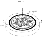
- FIG. 14 is a perspective view illustrating arrangement of the magnetization yokes at the inside and outside of the rotor of FIG. 2
- FIG. 15 is a cross-sectional view taken along line II-II of FIG. 14
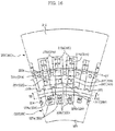
- FIG. 16 is a partial cross-sectional view taken along line III-III of FIG. 14 , illustrating magnetization of the magnets by the magnetization yokes.
- the magnetizing yokes 300 include an outer magnetizing yoke 310 disposed at the outside of the rotor 200, and an inner magnetizing yoke 320 disposed at the inside of the rotor 200.
- the outer magnetizing yoke 310 includes a ring-shaped body 312, a plurality of magnetizing teeth 314 extending inward from the body 312 in the radial direction of the body 312 and radially spaced apart from each other, and a plurality of magnetizing coils 316 wound around the magnetizing teeth 314.
- the magnetizing teeth 314 are disposed to be adjacent to the outer ends 220a of the rotor cores 220 during magnetization of the magnets 240.
- the gap G1 between the magnetizing teeth 314 and the outer ends 220a of the rotor cores 220 may be between about 0.2 mm and about 0.5 mm. If the gap G1 between the magnetizing teeth 314 and the outer ends 220a of the rotor cores 220 is less than 0.2 mm and thus too small, interference between the magnetizing teeth 314 and the outer ends 220a of the rotor cores 220 may be caused by the electromagnetic force generated between the outer magnetizing yoke 310 and the rotor 200 during magnetization.
- the gap G1 between the magnetizing teeth 314 and the outer ends 220a of the rotor cores 220 is greater than 0.5 mm, the magnetic path formed along the magnetizing teeth 314 and the rotor cores 220 is elongated, and thereby magnetization efficiency may be lowered.
- Electric current supplied to the magnetizing coils 316 alternately flows in opposite directions, and therefore magnetic flux is formed alternately in opposite directions at the magnetizing teeth 314 disposed along the circumferential direction of the rotor 200.
- the magnetic flux formed at the first magnetizing teeth 314a and the magnetic flux formed at the second magnetizing teeth 314b form a magnetic path through the first rotor core 221 adjacent to the first magnetizing teeth 314a, the first magnet 241 and the second rotor core 222 to magnetize the first magnet 241 in the circumferential direction (direction A) of the rotor 200.
- the second magnet 242 adjacent to the first magnet 241 is magnetized in the direction (direction B) opposite to the circumferential direction of the rotor 200.
- the inner magnetizing yoke 320 includes a ring-shaped body 322, a plurality of magnetizing teeth 324 extending outward from the body 322 in the radial direction of the body 322 and radially spaced apart from each other, and a plurality of magnetizing coils 326 wound around the magnetizing teeth 324.
- the magnetizing teeth 324 are disposed to be adjacent to the inner circumferential surface of the moulding 260 during magnetization of the magnets 240.
- the gap G2 between the magnetizing teeth 324 and the inner circumferential surface of the moulding 260 may be between about 0.5 mm and about 3 mm. If the gap G2 between the magnetizing teeth 324 and the inner circumferential surface of the moulding 260 is less than 0.5 mm and thus too small, interference between the gap G2 between the magnetizing teeth 324 and the inner circumferential surface of the moulding 260 may be caused by the electromagnetic force generated between the inner magnetizing yoke 320 and the rotor 200 during magnetization.
- the gap G2 between the gap G2 between the magnetizing teeth 324 and the inner circumferential surface of the moulding 260 is greater than 3 mm, the magnetic path formed along the magnetizing teeth 324 and the rotor cores 220 is elongated, and thereby magnetization efficiency may be lowered.
- the moulding 260 to support the inner ends 220b of the rotor cores 220 may be formed to have a thickness T between about 1.5 mm and about 2 mm. Accordingly, if the gap G2 between the magnetizing teeth 324 and the inner circumferential surface of the moulding 260 is maintained between about 0.5 mm and about 3 mm, the gap G3 between the magnetizing teeth 324 and the inner ends 220b of the rotor cores 220 is between about 2 mm and about 5 mm.
- a gap maintaining portion 270 is provided on the inner circumferential surface of the moulding 260 facing the magnetizing teeth 324.
- the gap maintaining portion 270 is formed to be substantially parallel with the direction in which the rotational axis of the rotor 200 extends.
- the length Lg of the gap maintaining portion 270 extending in the direction in which the rotational axis of the rotor 200 extends may be equal to or greater than the length Lm of the magnet 240. If the length Lg of the gap maintaining portion 270 is less than the length Lm of the magnet 240, the magnetic flux created at the inner magnetizing yokes 320 may not uniformly reach the magnets 240, and thereby magnetizing efficiency may be lowered.
- the gap G4 between one surface 320a of the inner magnetizing yoke 320 adjacent to the bottom surface 260a of the moulding 260 and one surface 240a of the magnet 240 adjacent to the bottom surface 260a of the moulding 260 may be smaller than 1/10 the length Lm of the magnet 240. If the gap G4 between the one surface 320a of the inner magnetizing yoke 320 and the one surface 240a of the magnet 240 exceeds 1/10 the length Lm of the magnet 240, the magnetic flux created at the inner magnetizing yokes 320 may not uniformly reach the magnets 240, and thereby magnetizing efficiency may be lowered.
- Electric current supplied to the magnetizing coils 326 flows alternately in opposite directions, and therefore magnetic flux is formed alternately in opposite directions at the magnetizing teeth 324 disposed along the circumferential direction of the rotor 200. That is, as shown in FIG. 16 , when current flows through the first coil 326a in the clockwise direction with respect to the axis along which the first magnetizing teeth 324a extend, current flows through the second coil 326b neighboring the first coil 326a in the counterclockwise direction with respect to the axis along which the second magnetizing teeth 324b extend, and the magnetic flux is formed at the first magnetizing teeth 324a toward the center of the rotor 200 and formed at the second magnetizing teeth 324b in a direction facing away from the center of the rotor 200.
- the magnetic flux formed at the first magnetizing teeth 324a and the magnetic flux formed at the second magnetizing teeth 324b form a magnetic path through the first rotor core 221 adjacent to the first magnetizing teeth 324a, the first magnet 241 and the second rotor core 222 to magnetize the first magnet 241 in the circumferential direction (direction A) of the rotor 200.
- the second magnet 242 adjacent to the first magnet 241 is magnetized in the direction (direction B) opposite to the circumferential direction of the rotor 200.
- outer magnetizing yokes 310 and the inner magnetizing yokes 320 are respectively disposed at the outside and inside of the rotor 200 to magnetize the magnets 240 at the same time, all regions of the magnets 240 may be uniformly magnetized.
- the body 312 and magnetizing teeth 314 of the outer magnetizing yoke 310 and the body 322 and magnetizing teeth 324 of the inner magnetizing yoke 320 may be integrally fabricated of cold-rolled steel sheet.
- a stacked core may be used to prevent magnetic flux from being reduced by eddy current formed at the core when impulse current is applied.
- the magnets are uniformly magnetized and thus the performance of a motor may be improved.
Landscapes
- Engineering & Computer Science (AREA)
- Power Engineering (AREA)
- Manufacturing & Machinery (AREA)
- Textile Engineering (AREA)
- Permanent Field Magnets Of Synchronous Machinery (AREA)
Abstract
Description
- The present invention relates to a motor and a washing machine having the same.
- A washing machine, which washes clothes using electricity, generally includes a tub to retain wash water, a drum rotatably installed in the tub and a motor to rotate the drum.
- The motor, which produces rotating power from electric energy, is provided with a stator and a rotor. The rotor is configured to electromagnetically interact with the stator, and is rotated by force acting between a magnetic field and current flowing through a coil.
- To increase torque produced per volume by concentrating magnetic flux, a magnetic flux concentrated-type motor includes a stator, a rotor disposed at the inside or outside of the stator to rotate by interacting with the stator and provided with segmented rotor cores disposed in the circumferential direction of the rotor and permanent magnets (hereinafter, referred to as "magnets") respectively coupled between the rotor cores.
- The magnets are coupled between the rotor cores by magnetizing the magnets and then coupling the magnetized magnets between the rotor cores (hereinafter, referred to as "pre-magnetization technique") or by coupling the magnets between the rotor cores and then magnetizing the magnets (hereinafter, referred to as "post-magnetization technique"). When the pre-magnetization technique is used, magnetization of the magnets is easily implemented, but attractive force or repulsive force acing between the magnets may make it difficult to couple the magnets between the rotor cores and even cause damage to surrounding devices. For this reason, the post-magnetization technique has often been used in recent years.
- For the post-magnetization technique which facilitates coupling of the magnets between the rotor cores, uniform magnetization may not be easy since magnetization proceeds after the magnets are coupled between the rotor cores. Therefore, there is a demand for an improved structure for the rotor.
- Therefore, it is an aspect of the present disclosure to provide a motor having an improved rotor which allows uniform magnetization of a magnet.
- Additional aspects of the disclosure will be set forth in part in the description which follows and, in part, will be apparent from the description, or may be learned by practice of the disclosure.
- In accordance with one aspect of the present disclosure, a motor includes a stator, and a rotor rotatably disposed at an inside or outside of the stator, wherein the rotor includes a plurality of rotor cores radially disposed, a plurality of magnets respectively disposed between the rotor cores, a moulding to support the rotor cores and the magnets and define an accommodation space to accommodate an inner magnetizing yoke to magnetize the magnets, and a gap maintaining portion formed at at least one section of an inner circumferential surface of the moulding in order to maintain a gap between an outer circumferential surface of the inner magnetization yoke and inner circumferential surfaces of the rotor cores between about 2 mm and about 5 mm when the inner magnetization yoke is accommodated in the accommodation space to magnetize the magnets.
- The gap maintaining portion may be substantially parallel with a direction in which a rotational axis of the rotor extends.
- A length of the gap maintaining portion formed in an axial direction of the rotor may be equal to or greater than a length of the magnets.
- When the inner magnetization yoke is accommodated in the accommodation space, a gap between one surface of the inner magnetizing yoke adjacent to a bottom surface of the moulding and one surface of the magnets adjacent to the bottom surface of the moulding may be smaller than 1/10 a length of the magnets.
- The inner circumferential surface of the moulding may be substantially perpendicular to a bottom surface of the moulding.
- In magnetizing the magnets, a gap between an outer magnetizing yoke disposed at an outside of the rotor to magnetize the magnets together with the inner magnetizing yoke and outer circumferential surfaces of the rotor cores may be between about 0.2 mm and about 0.5 mm.
- The rotor may include at least one first reinforcing rib formed on a bottom surface of the moulding to reinforce the rotor, and at least one second reinforcing rib formed on an outer surface of the moulding opposite to the bottom surface of the moulding to reinforce the rotor, wherein a length of the second reinforcing rib in a direction in which a radius of the rotor increases may be greater than a length of the first reinforcing rib.
- The first reinforcing rib and the second reinforcing rib may be radially disposed with respect to a center of rotation of the rotor.
- The magnets may include a first magnet and a second magnet forming magnetic fluxes in opposite directions toward one of the rotor cores disposed therebetween.
- The magnetic fluxes from the first magnet and the second magnet may be introduced into the one of the rotor cores disposed between the first magnet and the second magnet, combined, and discharged toward the stator.
- In accordance with another aspect of the present disclosure, a washing machine includes a body, a tub disposed in the body, a drum rotatably disposed in the tub, and a motor including a stator fixed to a rear surface of the tub and a rotor rotatably disposed inside the stator, wherein the rotor includes a plurality of magnets arranged in a circumferential direction of the rotor, a plurality of rotor cores alternated with the magnets in the circumferential direction of the rotor, magnetic fluxes formed at the magnets being concentrated at the rotor cores, and a moulding to support the rotor cores and the magnets and define an accommodation space to accommodate an inner magnetizing yoke to magnetize the magnets, wherein, when the inner magnetization yoke is accommodated in the accommodation space, a gap between one surface of the inner magnetizing yoke adjacent to a bottom surface of the moulding and one surface of the magnets adjacent to the bottom surface of the moulding is smaller than 1/10 a length of the magnets.
- When the inner magnetization yoke is accommodated in the accommodation space, an outer circumferential surface of the inner magnetizing yoke may be disposed parallel with an inner circumferential surface of the moulding.
- When the inner magnetization yoke is accommodated in the accommodation space, a gap between an outer circumferential surface of the inner magnetizing yoke and an inner circumferential surface of the moulding may be between about 0.5 mm and about 3 mm.
- An inner circumferential surface of the moulding may be substantially perpendicular to the bottom surface of the moulding.
- These and/or other aspects of the disclosure will become apparent and more readily appreciated from the following description of the embodiments, taken in conjunction with the accompanying drawings of which:
-
FIG. 1 is a view illustrating a washing machine according to an exemplary embodiment of the present disclosure; -
FIG. 2 is a view illustrating a tub and a stator and rotor of a motor of the washing machine according to the exemplary embodiment of the present disclosure, in which the tub, stator and rotor are separated from each other; -
FIG. 3 is a perspective view of the stator ofFIG. 2 ; -
FIG. 4 is an exploded perspective view illustrating constituents of the stator ofFIG. 3 , - which are separated from each other;
-
FIG. 5 is an exploded perspective view ofFIG. 4 taken at a different angle; -
FIG. 6 is an enlarged view of section 'A' ofFIG. 4 ; -
FIG. 7 is an enlarged view of section 'B' ofFIG. 2 ; -
FIGS. 8 and9 are perspective views of the rotor ofFIG. 2 ; -
FIG. 10 is a cross-sectional view taken along line I-I ofFIG. 9 ; -
FIG. 11 is a plan view illustrating the rotor cores and the magnets of the rotor ofFIG. 2 ; -
FIG. 12 is an enlarged view of section 'C' ofFIG. 11 ; -
FIG. 13 is a view illustrating coupling of a moulding to the rotor cores and the magnets shown inFIG. 12 ; -
FIG. 14 is a perspective view illustrating arrangement of the magnetization yokes at the inside and outside of the rotor ofFIG. 2 ; -
FIG. 15 is a cross-sectional view taken along line II-II ofFIG. 14 ; and -
FIG. 16 is a partial cross-sectional view taken along line III-III ofFIG. 14 , illustrating magnetization of the magnets by the magnetization yokes. - Reference will now be made in detail to the embodiments of the present disclosure, examples of which are illustrated in the accompanying drawings, wherein like reference numerals refer to like elements throughout. Hereinafter, a description will be given of a washing machine with a motor, which is applicable to all kinds of apparatuses including an air conditioner, an electric vehicle, a light rail transit system, an electric bicycle and a small generator that employ a motor as a power source. Hereinafter, a washing machine will be described as an example of application of the motor.
-
FIG. 1 is a view illustrating a washing machine according to an exemplary embodiment of the present disclosure. - As shown in
FIG. 1 , thewashing machine 1 includes acabinet 10 forming the external appearance of thewashing machine 1, atub 20 disposed within thecabinet 10, adrum 30 rotatably disposed in thetub 20, and amotor 40 to rotate thedrum 30. - The front portion of the
cabinet 10 is provided with aninlet 11 through which laundry may be inserted into thedrum 30. Theinlet 11 is opened and closed by adoor 12 installed at the front of thecabinet 10. - A
water supply pipe 50 to supply wash water to thetub 20 is installed at an upper portion of thetub 20. One side of thewater supply pipe 50 is connected to an external water supply source (not shown), and the other side of thewater supply pipe 50 is connected to adetergent supply unit 60. Thedetergent supply unit 60 is connected to thetub 20 through aconnection pipe 55. Water flowing into thewater supply pipe 50 is supplied to thetub 20 along with a detergent via thedetergent supply unit 60. - Installed at the bottom of the
tub 20 are adrain pump 70 anddrain pipe 75 to discharge water in thetub 20 from thecabinet 10. - A plurality of through
holes 31 is formed around thedrum 30 to allow flow of wash water therethrough, and a plurality oflifters 32 is installed on the inner circumferential surface of thedrum 30 to allow the laundry to tumble during rotation of thedrum 30. - The
drum 30 andmotor 40 are connected to each other through adrive shaft 80. Thedrive shaft 80 transmits the rotating power of themotor 40 to thedrum 30. One end of thedrive shaft 80 is connected to thedrum 30, and the other end of thedrive shaft 80 extends to the outside of therear wall 21 of thetub 20. - Installed at the
rear wall 21 of thetub 20 is a bearinghousing 82 by which thedrive shaft 80 is rotatably supported. Thebearing housing 82 may be formed of an aluminum alloy, and may be inserted into therear wall 21 of thetub 20 when thetub 20 is manufactured through injection moulding.Bearings 84 are installed between the bearinghousing 82 and thedrive shaft 80 to allow smooth rotation of thedrive shaft 80. -
FIG. 2 is a view illustrating a tub and a stator and rotor of a motor of the washing machine according to the exemplary embodiment of the present disclosure, in which the tub, stator and rotor are separated from each other, andFIG. 3 is a perspective view of the stator ofFIG. 2 .FIG. 4 is an exploded perspective view illustrating constituents of the stator ofFIG. 3 , which are separated from each other, andFIG. 5 is an exploded perspective view ofFIG. 4 taken at a different angle.FIG. 6 is an enlarged view of section 'A' ofFIG. 4 , andFIG. 7 is an enlarged view of section 'B' ofFIG. 2 . The coil is shown inFIGS. 4 and5 . - As shown in
FIGS. 1 to 7 , themotor 40 is coupled to the outside of thetub 20 to drive thedrum 30 in opposite directions. Themotor 40 includes astator 100 mounted to therear wall 20 of thetub 20, and arotor 200 disposed around thestator 100 to rotate through electromagnetic interaction with thestator 100. - The
stator 100 includes astator core 110 formed of a metal material, afirst insulator 120a and asecond insulator 120b covering both ends 110a and 110b of thestator core 110, aninsulation film 130 inserted between thefirst insulator 120a and thesecond insulator 120b, and acoil 140 wound around thefirst insulator 120a, thesecond insulator 120b and theinsulation film 130. Thestator core 110 may be formed by stacking metal plates processed through press working. Thefirst insulator 120a,second insulator 120b andinsulation film 130 may be formed of electrical insulators. - The
stator core 110 includes a ring-shapedcore body 112, and a plurality ofcore teeth 114 extending inward from the inner circumferential surface of thecore body 112 in the radial direction of thecore body 112 and arranged spaced apart from each other along the inner circumferential surface of thecore body 112. - The
first insulator 120a includes afirst insulator body 122a having a shape corresponding to that of thecore body 112, and a plurality offirst insulator teeth 124a having a shape corresponding that of thecore teeth 114. Thefirst insulator teeth 124a extend inward in the radial direction of thefirst insulator body 122a and are arranged spaced apart from each other along the inner circumferential surface of thefirst insulator body 122a. - The
first insulator 120a further includes a plurality ofconnection ribs 126 connected to thesecond insulator 120b, and first throughholes 128 to fix thetub 20 to therear wall 21 therethrough. Theconnection ribs 126 protrude from thefirst insulator body 122a toward thesecond insulator 120b, and are arranged spaced a predetermined distance apart from each other in the circumferential direction of thefirst insulator body 122a and adapted to be connected to thesecond insulator 120b when thestator core 110,first insulator 120a andsecond insulator 120b are coupled to each other. The first throughholes 128 are formed through thefirst insulator body 122a and theconnection rib 126.Sleeves 170 may be inserted into the first throughholes 128 to reinforce fastening of thestator 100 to thetub 20. - The length of the
connection rib 126 protruding from thefirst insulator 120a may vary depending on the stack height of thestator core 110. That is, if the stack of thestator core 110 is high, theconnection rib 126 may be formed to have a long protruding length. If the stack ofstator core 110 is short, theconnection rib 126 may be formed to have a short protruding length. In case that theconnection ribs 126 and thefirst insulator 120a are integrally formed through injection moulding, a mould for injection moulding of thefirst insulator 120a does not need to be separately fabricated whenever the length of theconnection ribs 126 changes according to change in the stack height of thestator core 110, but one mould may be used in common. The length of theconnection ribs 126 may be adjusted during fabrication of thefirst insulator 120a through injection moulding by filling a portion of the mold for formation of theconnection ribs 126, which is pre-formed to have a deep depth, to the height corresponding to the protruding length of theconnection ribs 126, using a tool such as a jig. - The
second insulator 120b includes asecond insulator body 122b having a shape corresponding to that of thecore body 112, and a plurality ofsecond insulator teeth 124b having a shape corresponding to that of thecore teeth 114. Thesecond insulator teeth 124b extend inward in the radial direction of thesecond insulator body 122b and are arranged spaced apart from each other along the inner circumferential surface of thesecond insulator body 122b. - The
second insulator 120b further includes a plurality of fixingribs 127 connected to thetub 20, second throughholes 129 formed through thesecond insulator body 122b and the fixingrib 127, and a plurality of fixingpins 123 protruding from surfaces of the fixingribs 127 facing therear wall 21 of thetub 20 toward therear wall 21 of thetub 20. - The fixing
ribs 127 protrude from thesecond insulator body 122b toward therear wall 21 of thetub 20, and are arranged spaced a predetermined distance apart from each other in the circumferential direction of thesecond insulator body 122b. The fixingribs 127 contact therear wall 21 of thetub 20 when thestator 110 is coupled to thetub 20. - The fixing pins 123 are adapted to determine the position of the
stator 100 before being inserted into therear wall 21 of thetub 20 to fix thestator 100 to therear wall 21 of thetub 20. The second throughholes 129 are formed through thesecond insulator body 122b and the fixingribs 127, and are disposed to be concentric with the first throughholes 128.Sleeves 170 may be inserted into the second throughholes 129 to reinforce fastening of thestator 100 to thetub 20. - First accommodation holes 161 to accommodate the fixing pins 123 inserted thereinto are provided at the
rear wall 21 of thetub 20 to which thestator 100 is mounted. The bearinghousing 82 inserted into therear wall 21 of thetub 20 is provided with second accommodation holes 162 to accommodate fixingmembers 150 inserted thereinto. At least twofirst accommodation holes 161 and at least two second accommodation holes 162 are arranged spaced apart from each other in the circumferential direction of thetub 20. - The
first accommodation holes 161 allow the position of thestator 100 to be determined before the fixing pins 142 are accommodated therein to fix thestator 100 to therear wall 21 of thetub 20, while the second accommodation holes 162 accommodate the fixingmembers 150 penetrating thesleeves 170, thereby allowing thestator 100 to be fixed to therear wall 21 of thetub 20. - The bearing
housing 82 is inserted into therear wall 21 of thetub 20 to reinforce thetub 20, and directly coupled to thestator 100 through the second accommodation holes 162 to allow thestator 100 to be stably fixed to therear wall 21 of thetub 20. - Although not shown in
FIGS. 1 to 7 ,first accommodation holes 161 and the second accommodation holes 162 may be provided in the bearinghousing 82. - The
insulation film 130 is inserted between thefirst insulator 120a and thesecond insulator 120b. - The
insulation film 130 is formed approximately in a bracket shape, and disposed between one of thefirst insulator teeth 124a and one of thesecond insulator teeth 124b neighboring each other to electrically insulate thestator core 110 and thecoil 140. Theinsulation film 130 may be formed of paper or plastics which are electrically nonconductive. - The
coil 140 is wound around thefirst insulator 120a,second insulator 120b andinsulation film 130. When 3-phase alternating current (AC) power is supplied to thecoil 140, magnetic flux is created at thestator core 110. The magnetic flux created at thestator core 110 interacts with the magnetic flux created at therotor 200 to rotate therotor 200. -
FIGS. 8 and9 are perspective views of the rotor ofFIG. 2 , andFIG. 10 is a cross-sectional view taken along line I-I ofFIG. 9 .FIG. 11 is a plan view illustrating the rotor cores and the magnets of the rotor ofFIG. 2 ,FIG. 12 is an enlarged view of section 'C' ofFIG. 11 , andFIG. 13 is a view illustrating coupling of a moulding to the rotor cores and the magnets shown inFIG. 12 . - As shown in
FIGS. 8 to 13 , therotor 200 includes a plurality ofrotor cores 220 disposed in a radial shape, a plurality ofmagnets 240 respectively disposed between therotor cores 220, and a moulding (body) 260 to support therotor cores 220 and themagnets 240. - The
rotor cores 220 support themagnets 240, and form a magnetic path created at themagnets 240. Therotor cores 220 are arranged along the circumferential direction of therotor 200, and respectively disposed spaced apart from each other between therotor cores 220 to accommodate themagnets 240. - Each of the
rotor cores 220 includes aninner end 220b disposed adjacent to the center of therotor 200, and anouter end 220a disposed adjacent to thecore teeth 114 of thestator core 110 to define an air gap in cooperation with thecore teeth 114. The width of each of therotor cores 220 in a circumferential direction increases from theinner end 220b thereof to theouter end 220a thereof. Therotor cores 220 may be formed by stacking silicon steel plates processed through press working. - In addition, each of the
segmented rotor cores 220 includes a throughhole 223 and acoupling groove 224. The throughhole 223 andcoupling groove 224 are coupled to themoulding 260 that supports therotor cores 220. - The through
hole 223 is formed through the body of therotor core 220 such that themoulding 260 is accommodated therein and coupled thereto during fabrication of themoulding 260 through injection moulding. The diameter of the throughhole 223 may be between about 1.5 mm and about 5 mm. If the diameter of the throughhole 223 is too small, therotor cores 220 may not be securely supported by themoulding 260. If the diameter of the throughhole 223 is too large, the magnetic flux concentrated at therotor core 220 may interrupt creation of a magnetic path through theouter end 220a of therotor core 220. - In addition, a plurality of through
holes 223 may be disposed in the radial direction of therotor 200. If the number of the throughholes 223 is too large, they may interrupt creation of a magnetic path through theouter end 220a of therotor core 220 as in the case of the throughhole 223 having too large a diameter, which may cause the magnetic flux concentrated at therotor core 220 to interrupt creation of the magnetic path through theouter end 220a of therotor core 220. Therefore, the number may be equal to or less than three. - The
coupling groove 224 includes afirst accommodation portion 224a formed approximately at the center of theinner end 220b of therotor core 220 and having a width in a circumferential direction which decreases as thefirst accommodation portion 224a extends from theinner end 220b toward theouter end 220a, and asecond accommodation portion 224b connected with thefirst accommodation portion 224a, and having a width which increases as thesecond accommodation portion 224b extends from theinner end 220b toward theouter end 220a. - The
first accommodation portion 224a and thesecond accommodation portion 224b accommodate themoulding 260 when themoulding 260 is fabricated through injection moulding such therotor core 220 and themoulding 260 are securely coupled to each other. - The
magnets 240, each of which is disposed between corresponding ones of therotor cores 220, are arranged along the circumferential direction of therotor 200 to be radially positioned with respect to the center of therotor 200. Themagnet 240 may be a magnet containing a rare-earth element such as neodymium and samarium or a ferrite magnet which may semi-permanently maintain the magnetic property of high energy density. - The magnetic fluxes created at the
magnets 240 are arranged along the circumferential direction of therotor 200. Any two neighboring ones of themagnets 240 are disposed such that the portions thereof having the same polarity face each other. If a magnetic circuit is formed in this way, the magnetic flux generated by themagnets 240 is concentrated, and therefore it may be possible to reduce the size of themotor 40 while improving the performance thereof. - The
moulding 260 includes aserration 262 coupled to thedrive shaft 80,heat dissipation outlets 264 to dissipate heat generated during rotation of therotor 200, and a plurality of reinforcingribs 269. - The
serration 262 includes ashaft hole 262a into which thedrive shaft 80 is inserted to be coupled thereto. Theserration 262 may be formed of a metal material such that thedrive shaft 80 is firmly coupled thereto, and may be inserted into a mold for fabrication of themoulding 260 during formation of themoulding 260 through injection moulding. - The reinforcing
ribs 269 include at least one first reinforcingrib 269a radially formed on thebottom surface 260a of themoulding 260 around ashaft hole 262a to reinforce therotor 200, and at least one second reinforcingrib 269b radially formed on theouter surface 260b of themoulding 260 opposite to thebottom surface 260a of themoulding 260 around theshaft hole 262a to reinforce therotor 200. The portions of the first reinforcingrib 269 and the second reinforcingrib 269b to which theserration 262 is coupled are formed to be thick such that theserration 262 is firmly coupled to themoulding 260. The length L1 of the first reinforcingrib 269a is shorter than the length L2 of the second reinforcingrib 269b in the direction in which the radius of therotor 200 increases. If the length L1 of the first reinforcingrib 269a is too long in the direction in which the radius of therotor 200 increases, interference with the inner magnetizingyoke 320 to magnetize themagnets 240 may occur. - The
moulding 260 further includes a ring-shapedbridge 266 to support therotor cores 220 and themagnets 240, and a first tothird coupling ribs moulding 260 with therotor cores 220 and themagnets 240. - The
first coupling rib 263 includes a firstinclined protrusion 263a protruding outward from the outer circumferential surface of thebridge 266 in the radial direction of therotor 200 and inclined in a direction in which the width thereof decreases as thefirst coupling rib 263 extends outward, and a secondinclined protrusion 263b formed from the firstinclined protrusion 263a to be inclined in a direction in which the width thereof increases as the secondinclined protrusion 263b extends from the firstinclined protrusion 263a. - The first
inclined protrusion 263a is accommodated in and coupled to thefirst accommodation portion 224a and the secondinclined protrusion 263b is accommodated in and coupled to thesecond accommodation portion 224b, such that therotor core 200 is coupled to thebridge 266. Particularly, the secondinclined protrusion 263b is formed in the shape of a step whose width increases in the circumferential direction of therotor 200, thereby effectively preventing therotor core 220 from being separated from the bridge 226 by centrifugal force generated during rotation of therotor 200. - The
second coupling rib 265 is accommodated in aspace 229 formed by respective surfaces of neighboringrotor cores 220 facing each other and one end of amagnet 240 disposed between the neighboringrotor cores 220 to reinforce therotor 200 and prevent exposure of themagnet 240 to the outside. - The
third coupling rib 268 is accommodated in and coupled to the throughhole 223 provided in therotor core 220 to prevent, in cooperation with the secondinclined protrusion 263b, therotor core 220 from being separated from thebridge 266. - The first to
third coupling ribs coupling groove 224, thespace 229 formed by therotor cores 220 and themagnet 240, and the throughhole 229 during the process of integration of themoulding 260 with therotor cores 220 and themagnets 240 using the insert injection moulding technique. - When coupled to a plurality of the
rotor cores 220 by themoulding 260, themagnets 240 are magnetized by the magnetizingyokes 300 disposed at the inside and outside of therotor 200. -
FIG. 14 is a perspective view illustrating arrangement of the magnetization yokes at the inside and outside of the rotor ofFIG. 2 , andFIG. 15 is a cross-sectional view taken along line II-II ofFIG. 14 .FIG. 16 is a partial cross-sectional view taken along line III-III ofFIG. 14 , illustrating magnetization of the magnets by the magnetization yokes. - As shown in
FIGS. 14 to 16 , the magnetizingyokes 300 include an outer magnetizingyoke 310 disposed at the outside of therotor 200, and aninner magnetizing yoke 320 disposed at the inside of therotor 200. - The outer magnetizing
yoke 310 includes a ring-shapedbody 312, a plurality of magnetizingteeth 314 extending inward from thebody 312 in the radial direction of thebody 312 and radially spaced apart from each other, and a plurality of magnetizingcoils 316 wound around the magnetizingteeth 314. - The magnetizing
teeth 314 are disposed to be adjacent to the outer ends 220a of therotor cores 220 during magnetization of themagnets 240. The gap G1 between the magnetizingteeth 314 and the outer ends 220a of therotor cores 220 may be between about 0.2 mm and about 0.5 mm. If the gap G1 between the magnetizingteeth 314 and the outer ends 220a of therotor cores 220 is less than 0.2 mm and thus too small, interference between the magnetizingteeth 314 and the outer ends 220a of therotor cores 220 may be caused by the electromagnetic force generated between the outer magnetizingyoke 310 and therotor 200 during magnetization. If the gap G1 between the magnetizingteeth 314 and the outer ends 220a of therotor cores 220 is greater than 0.5 mm, the magnetic path formed along the magnetizingteeth 314 and therotor cores 220 is elongated, and thereby magnetization efficiency may be lowered. - Electric current supplied to the magnetizing
coils 316 alternately flows in opposite directions, and therefore magnetic flux is formed alternately in opposite directions at the magnetizingteeth 314 disposed along the circumferential direction of therotor 200. - That is, as shown in
FIG. 16 , when current flows through thefirst coil 316a in the counterclockwise direction with respect to the axis along which the first magnetizingteeth 314a extend, current flows through thesecond coil 316b neighboring thefirst coil 316a in the clockwise direction with respect to the axis along which the second magnetizingteeth 314b extends, and the magnetic flux is formed at the first magnetizingteeth 314a toward the center of therotor 200 and formed at the second magnetizingteeth 314b in a direction facing away from the center of therotor 200. - As shown in
FIG. 16 , the magnetic flux formed at the first magnetizingteeth 314a and the magnetic flux formed at the second magnetizingteeth 314b form a magnetic path through thefirst rotor core 221 adjacent to the first magnetizingteeth 314a, thefirst magnet 241 and thesecond rotor core 222 to magnetize thefirst magnet 241 in the circumferential direction (direction A) of therotor 200. Similarly, thesecond magnet 242 adjacent to thefirst magnet 241 is magnetized in the direction (direction B) opposite to the circumferential direction of therotor 200. - The
inner magnetizing yoke 320 includes a ring-shapedbody 322, a plurality of magnetizingteeth 324 extending outward from thebody 322 in the radial direction of thebody 322 and radially spaced apart from each other, and a plurality of magnetizingcoils 326 wound around the magnetizingteeth 324. - The magnetizing
teeth 324 are disposed to be adjacent to the inner circumferential surface of themoulding 260 during magnetization of themagnets 240. The gap G2 between the magnetizingteeth 324 and the inner circumferential surface of themoulding 260 may be between about 0.5 mm and about 3 mm. If the gap G2 between the magnetizingteeth 324 and the inner circumferential surface of themoulding 260 is less than 0.5 mm and thus too small, interference between the gap G2 between the magnetizingteeth 324 and the inner circumferential surface of themoulding 260 may be caused by the electromagnetic force generated between the inner magnetizingyoke 320 and therotor 200 during magnetization. If the gap G2 between the gap G2 between the magnetizingteeth 324 and the inner circumferential surface of themoulding 260 is greater than 3 mm, the magnetic path formed along the magnetizingteeth 324 and therotor cores 220 is elongated, and thereby magnetization efficiency may be lowered. - The
moulding 260 to support the inner ends 220b of therotor cores 220 may be formed to have a thickness T between about 1.5 mm and about 2 mm. Accordingly, if the gap G2 between the magnetizingteeth 324 and the inner circumferential surface of themoulding 260 is maintained between about 0.5 mm and about 3 mm, the gap G3 between the magnetizingteeth 324 and the inner ends 220b of therotor cores 220 is between about 2 mm and about 5 mm. - As such, to maintain the gap G2 between the inner circumferential surface of the
moulding 260 and the magnetizingteeth 324 of the inner magnetizingyoke 320 between about 0.5 mm and about 3 mm, agap maintaining portion 270 is provided on the inner circumferential surface of themoulding 260 facing the magnetizingteeth 324. Thegap maintaining portion 270 is formed to be substantially parallel with the direction in which the rotational axis of therotor 200 extends. When the inner magnetizing yokes 320 are accommodated and disposed inside of themoulding 260, the outer circumferential surfaces of the magnetizingteeth 324 are disposed substantially parallel with thegap maintaining portion 270. - The length Lg of the
gap maintaining portion 270 extending in the direction in which the rotational axis of therotor 200 extends may be equal to or greater than the length Lm of themagnet 240. If the length Lg of thegap maintaining portion 270 is less than the length Lm of themagnet 240, the magnetic flux created at the inner magnetizing yokes 320 may not uniformly reach themagnets 240, and thereby magnetizing efficiency may be lowered. - In addition, when the inner magnetizing yokes 320 are accommodated and disposed in the
moulding 260, the gap G4 between onesurface 320a of the inner magnetizingyoke 320 adjacent to thebottom surface 260a of themoulding 260 and onesurface 240a of themagnet 240 adjacent to thebottom surface 260a of themoulding 260 may be smaller than 1/10 the length Lm of themagnet 240. If the gap G4 between the onesurface 320a of the inner magnetizingyoke 320 and the onesurface 240a of themagnet 240 exceeds 1/10 the length Lm of themagnet 240, the magnetic flux created at the inner magnetizing yokes 320 may not uniformly reach themagnets 240, and thereby magnetizing efficiency may be lowered. - Electric current supplied to the magnetizing
coils 326 flows alternately in opposite directions, and therefore magnetic flux is formed alternately in opposite directions at the magnetizingteeth 324 disposed along the circumferential direction of therotor 200. That is, as shown inFIG. 16 , when current flows through thefirst coil 326a in the clockwise direction with respect to the axis along which the first magnetizingteeth 324a extend, current flows through the second coil 326b neighboring thefirst coil 326a in the counterclockwise direction with respect to the axis along which the second magnetizingteeth 324b extend, and the magnetic flux is formed at the first magnetizingteeth 324a toward the center of therotor 200 and formed at the second magnetizingteeth 324b in a direction facing away from the center of therotor 200. - As shown in
FIG. 16 , the magnetic flux formed at the first magnetizingteeth 324a and the magnetic flux formed at the second magnetizingteeth 324b form a magnetic path through thefirst rotor core 221 adjacent to the first magnetizingteeth 324a, thefirst magnet 241 and thesecond rotor core 222 to magnetize thefirst magnet 241 in the circumferential direction (direction A) of therotor 200. Similarly, thesecond magnet 242 adjacent to thefirst magnet 241 is magnetized in the direction (direction B) opposite to the circumferential direction of therotor 200. - As the outer magnetizing
yokes 310 and the inner magnetizing yokes 320 are respectively disposed at the outside and inside of therotor 200 to magnetize themagnets 240 at the same time, all regions of themagnets 240 may be uniformly magnetized. - In the meantime, the
body 312 and magnetizingteeth 314 of the outer magnetizingyoke 310 and thebody 322 and magnetizingteeth 324 of the inner magnetizingyoke 320 may be integrally fabricated of cold-rolled steel sheet. In addition, a stacked core may be used to prevent magnetic flux from being reduced by eddy current formed at the core when impulse current is applied. - As is apparent from the above description, by disposing magnetizing yokes at the inside and outside of a rotor, the magnets are uniformly magnetized and thus the performance of a motor may be improved.
- Although a few embodiments of the present disclosure have been shown and described, it would be appreciated by those skilled in the art that changes may be made in these embodiments without departing from the principles of the invention, the scope of which is defined in the claims.
Claims (11)
- A motor comprising:a stator; anda rotor rotatably disposed at an inside or outside of the stator,wherein the rotor comprises:a plurality of rotor cores radially disposed;a plurality of magnets respectively disposed between the rotor cores;a moulding to support the rotor cores and the magnets and define an accommodation space to accommodate an inner magnetizing yoke to magnetize the magnets; anda gap maintaining portion formed at at least one section of an inner circumferential surface of the moulding in order to maintain a gap between an outer circumferential surface of the inner magnetization yoke and inner circumferential surfaces of the rotor cores between about 2 mm and about 5 mm when the inner magnetization yoke is accommodated in the accommodation space to magnetize the magnets.
- The motor according to claim 1, wherein the gap maintaining portion is substantially parallel with a direction in which a rotational axis of the rotor extends.
- The motor according to claim 1 or 2, wherein a length of the gap maintaining portion formed in an axial direction of the rotor is equal to or greater than a length of the magnets.
- The motor according to any one of the preceding claims, wherein, when the inner magnetization yoke is accommodated in the accommodation space, a gap between one surface of the inner magnetizing yoke adjacent to a bottom surface of the moulding and one surface of the magnets adjacent to the bottom surface of the moulding is smaller than 1/10 of a length of the magnets.
- The motor according to any one of the preceding claims, wherein the inner circumferential surface of the moulding is substantially perpendicular to a bottom surface of the moulding.
- The motor according to any one of the preceding claims, wherein, in magnetizing the magnets, a gap between an outer magnetizing yoke disposed at an outside of the rotor to magnetize the magnets together with the inner magnetizing yoke and outer circumferential surfaces of the rotor cores is between about 0.2 mm and about 0.5 mm.
- The motor according to any one of the preceding claims, wherein the rotor comprises:at least one first reinforcing rib formed on a bottom surface of the moulding to reinforce the rotor; andat least one second reinforcing rib formed on an outer surface of the moulding opposite to the bottom surface of the moulding to reinforce the rotor,wherein a length of the second reinforcing rib in a direction in which a radius of the rotor increases is greater than a length of the first reinforcing rib.
- The motor according to claim 7, wherein the first reinforcing rib and the second reinforcing rib are radially disposed with respect to a center of rotation of the rotor.
- The motor according to any one of the preceding claims, wherein the magnets comprises a first magnet and a second magnet forming magnetic fluxes in opposite directions toward one of the rotor cores disposed therebetween.
- The motor according to claim 9, wherein the magnetic fluxes from the first magnet and the second magnet are introduced into the one of the rotor cores disposed between the first magnet and the second magnet, combined, and discharged toward the stator.
- A washing machine having a drum, and a motor according to any one of the preceding claims for driving the drum.
Applications Claiming Priority (1)
| Application Number | Priority Date | Filing Date | Title |
|---|---|---|---|
| KR1020120115097A KR20140049201A (en) | 2012-10-16 | 2012-10-16 | Motor and washing machine having the same |
Publications (2)
| Publication Number | Publication Date |
|---|---|
| EP2722971A2 true EP2722971A2 (en) | 2014-04-23 |
| EP2722971A3 EP2722971A3 (en) | 2017-07-26 |
Family
ID=49356265
Family Applications (1)
| Application Number | Title | Priority Date | Filing Date |
|---|---|---|---|
| EP13188385.2A Withdrawn EP2722971A3 (en) | 2012-10-16 | 2013-10-11 | Motor and washing maching having the same |
Country Status (4)
| Country | Link |
|---|---|
| US (1) | US20140102151A1 (en) |
| EP (1) | EP2722971A3 (en) |
| KR (1) | KR20140049201A (en) |
| CN (1) | CN103795163A (en) |
Cited By (5)
| Publication number | Priority date | Publication date | Assignee | Title |
|---|---|---|---|---|
| EP3070199A1 (en) * | 2015-03-19 | 2016-09-21 | Whirlpool Corporation | Laundry washing or drying machine |
| EP3349332A4 (en) * | 2015-09-08 | 2019-05-01 | LG Electronics Inc. | ROTOR AND MOTOR COMPRISING IT |
| US10326325B2 (en) | 2015-09-08 | 2019-06-18 | Lg Electronics Inc. | Rotor and motor including the same |
| WO2021032480A1 (en) * | 2019-08-22 | 2021-02-25 | Webasto SE | Rotor device and stator device for a flat, brushless electric motor and flat, brushless electric motor for a roof system of an automobile |
| US20230064111A1 (en) * | 2021-08-30 | 2023-03-02 | Whirlpool Corporation | Structured geometry for a tub rear wall of a laundry appliance |
Families Citing this family (2)
| Publication number | Priority date | Publication date | Assignee | Title |
|---|---|---|---|---|
| KR102252508B1 (en) * | 2015-01-05 | 2021-05-14 | 엘지전자 주식회사 | laundry machine |
| EP3657639B1 (en) | 2018-11-26 | 2025-09-10 | LG Electronics Inc. | Motor |
Family Cites Families (7)
| Publication number | Priority date | Publication date | Assignee | Title |
|---|---|---|---|---|
| JP2512611B2 (en) * | 1990-07-12 | 1996-07-03 | 信越化学工業株式会社 | Permanent magnet single magnetizing device for magnetic pole of rotating machine |
| JPH1052007A (en) * | 1996-07-29 | 1998-02-20 | Shin Etsu Chem Co Ltd | Magnetized yoke |
| US7350283B2 (en) * | 2003-10-02 | 2008-04-01 | The Bergquist Torrington Company | Method for making rotor for permanent magnet electric machine |
| KR100631533B1 (en) * | 2004-09-13 | 2006-10-09 | 엘지전자 주식회사 | Rotor structure for bldc motor |
| KR101460133B1 (en) * | 2009-08-17 | 2014-11-11 | 삼성전자 주식회사 | A motor for a washing machine and a washing machine having the same |
| CN201786562U (en) * | 2010-08-06 | 2011-04-06 | 国电联合动力技术有限公司 | Dual-stator direct drive permanent magnet wind-driven generator |
| EP2509192A2 (en) * | 2011-04-08 | 2012-10-10 | Samsung Electronics Co., Ltd. | Motor and magnetizing apparatus and magnetizing method of motor |
-
2012
- 2012-10-16 KR KR1020120115097A patent/KR20140049201A/en not_active Withdrawn
-
2013
- 2013-10-11 EP EP13188385.2A patent/EP2722971A3/en not_active Withdrawn
- 2013-10-15 US US14/053,783 patent/US20140102151A1/en not_active Abandoned
- 2013-10-16 CN CN201310485197.8A patent/CN103795163A/en active Pending
Non-Patent Citations (1)
| Title |
|---|
| None |
Cited By (7)
| Publication number | Priority date | Publication date | Assignee | Title |
|---|---|---|---|---|
| EP3070199A1 (en) * | 2015-03-19 | 2016-09-21 | Whirlpool Corporation | Laundry washing or drying machine |
| US9850614B2 (en) | 2015-03-19 | 2017-12-26 | Whirlpool Corporation | Machine for washing or drying laundry |
| EP3349332A4 (en) * | 2015-09-08 | 2019-05-01 | LG Electronics Inc. | ROTOR AND MOTOR COMPRISING IT |
| US10326325B2 (en) | 2015-09-08 | 2019-06-18 | Lg Electronics Inc. | Rotor and motor including the same |
| WO2021032480A1 (en) * | 2019-08-22 | 2021-02-25 | Webasto SE | Rotor device and stator device for a flat, brushless electric motor and flat, brushless electric motor for a roof system of an automobile |
| US20230064111A1 (en) * | 2021-08-30 | 2023-03-02 | Whirlpool Corporation | Structured geometry for a tub rear wall of a laundry appliance |
| US12559877B2 (en) * | 2021-08-30 | 2026-02-24 | Whirlpool Corporation | Structured geometry for a tub rear wall of a laundry appliance |
Also Published As
| Publication number | Publication date |
|---|---|
| KR20140049201A (en) | 2014-04-25 |
| EP2722971A3 (en) | 2017-07-26 |
| CN103795163A (en) | 2014-05-14 |
| US20140102151A1 (en) | 2014-04-17 |
Similar Documents
| Publication | Publication Date | Title |
|---|---|---|
| KR101900456B1 (en) | Motor and washing machine having the same | |
| CN103001357B (en) | Motor and there is the washing machine of this motor | |
| CN203707906U (en) | A rotor of a motor | |
| KR100903519B1 (en) | Permanent magnet embedded motor and air suction device using same | |
| US9419482B2 (en) | Motor and rotor thereof | |
| EP2202867B1 (en) | Slim type stator | |
| US20130057103A1 (en) | Motor and washing machine having the same | |
| US20140102151A1 (en) | Motor and washing machine having the same | |
| US20100156216A1 (en) | Slim type stator having integrated cover structure, slim type motor and direct drive apparatus for drum-washing machine including the same | |
| KR20150063217A (en) | Motor and washing machine having the same | |
| CN103248144B (en) | Motor and there is the washing machine of this motor | |
| KR20130027417A (en) | Motor and washing machine having the same | |
| US20060055263A1 (en) | Rotor of BLDC motor | |
| US9546445B2 (en) | Motor and washing machine having the same | |
| KR20140036339A (en) | Motor | |
| US9431866B2 (en) | Motor and washing machine having the same | |
| KR102526938B1 (en) | Rotor for an interior permanent magnet motor and a motor with the same | |
| US20140070653A1 (en) | Motor | |
| KR20130090165A (en) | Motor | |
| JP2017221069A (en) | Magnet motor and washing machine with the same | |
| JP3679624B2 (en) | Permanent magnet rotating electric machine | |
| KR20030050707A (en) | Interior permanent magnet type motor | |
| KR20140043259A (en) | Motor and washing machine having same |
Legal Events
| Date | Code | Title | Description |
|---|---|---|---|
| PUAI | Public reference made under article 153(3) epc to a published international application that has entered the european phase |
Free format text: ORIGINAL CODE: 0009012 |
|
| AK | Designated contracting states |
Kind code of ref document: A2 Designated state(s): AL AT BE BG CH CY CZ DE DK EE ES FI FR GB GR HR HU IE IS IT LI LT LU LV MC MK MT NL NO PL PT RO RS SE SI SK SM TR |
|
| AX | Request for extension of the european patent |
Extension state: BA ME |
|
| PUAL | Search report despatched |
Free format text: ORIGINAL CODE: 0009013 |
|
| AK | Designated contracting states |
Kind code of ref document: A3 Designated state(s): AL AT BE BG CH CY CZ DE DK EE ES FI FR GB GR HR HU IE IS IT LI LT LU LV MC MK MT NL NO PL PT RO RS SE SI SK SM TR |
|
| AX | Request for extension of the european patent |
Extension state: BA ME |
|
| RIC1 | Information provided on ipc code assigned before grant |
Ipc: D06F 37/20 20060101ALI20170622BHEP Ipc: H02K 15/03 20060101ALI20170622BHEP Ipc: H02K 1/27 20060101AFI20170622BHEP |
|
| STAA | Information on the status of an ep patent application or granted ep patent |
Free format text: STATUS: THE APPLICATION HAS BEEN PUBLISHED |
|
| STAA | Information on the status of an ep patent application or granted ep patent |
Free format text: STATUS: THE APPLICATION IS DEEMED TO BE WITHDRAWN |
|
| 18D | Application deemed to be withdrawn |
Effective date: 20180127 |