EP2722935B1 - Electrical connector comprising a sealing element and assembly process - Google Patents
Electrical connector comprising a sealing element and assembly process Download PDFInfo
- Publication number
- EP2722935B1 EP2722935B1 EP20130187922 EP13187922A EP2722935B1 EP 2722935 B1 EP2722935 B1 EP 2722935B1 EP 20130187922 EP20130187922 EP 20130187922 EP 13187922 A EP13187922 A EP 13187922A EP 2722935 B1 EP2722935 B1 EP 2722935B1
- Authority
- EP
- European Patent Office
- Prior art keywords
- sealing layer
- connector
- conductors
- sealing
- way
- Prior art date
- Legal status (The legal status is an assumption and is not a legal conclusion. Google has not performed a legal analysis and makes no representation as to the accuracy of the status listed.)
- Active
Links
Images




Classifications
-
- H—ELECTRICITY
- H01—ELECTRIC ELEMENTS
- H01R—ELECTRICALLY-CONDUCTIVE CONNECTIONS; STRUCTURAL ASSOCIATIONS OF A PLURALITY OF MUTUALLY-INSULATED ELECTRICAL CONNECTING ELEMENTS; COUPLING DEVICES; CURRENT COLLECTORS
- H01R13/00—Details of coupling devices of the kinds covered by groups H01R12/70 or H01R24/00 - H01R33/00
- H01R13/46—Bases; Cases
- H01R13/52—Dustproof, splashproof, drip-proof, waterproof, or flameproof cases
- H01R13/5219—Sealing means between coupling parts, e.g. interfacial seal
- H01R13/5221—Sealing means between coupling parts, e.g. interfacial seal having cable sealing means
-
- H—ELECTRICITY
- H01—ELECTRIC ELEMENTS
- H01R—ELECTRICALLY-CONDUCTIVE CONNECTIONS; STRUCTURAL ASSOCIATIONS OF A PLURALITY OF MUTUALLY-INSULATED ELECTRICAL CONNECTING ELEMENTS; COUPLING DEVICES; CURRENT COLLECTORS
- H01R13/00—Details of coupling devices of the kinds covered by groups H01R12/70 or H01R24/00 - H01R33/00
- H01R13/46—Bases; Cases
- H01R13/52—Dustproof, splashproof, drip-proof, waterproof, or flameproof cases
- H01R13/5205—Sealing means between cable and housing, e.g. grommet
- H01R13/5208—Sealing means between cable and housing, e.g. grommet having at least two cable receiving openings
-
- H—ELECTRICITY
- H01—ELECTRIC ELEMENTS
- H01R—ELECTRICALLY-CONDUCTIVE CONNECTIONS; STRUCTURAL ASSOCIATIONS OF A PLURALITY OF MUTUALLY-INSULATED ELECTRICAL CONNECTING ELEMENTS; COUPLING DEVICES; CURRENT COLLECTORS
- H01R43/00—Apparatus or processes specially adapted for manufacturing, assembling, maintaining, or repairing of line connectors or current collectors or for joining electric conductors
- H01R43/16—Apparatus or processes specially adapted for manufacturing, assembling, maintaining, or repairing of line connectors or current collectors or for joining electric conductors for manufacturing contact members, e.g. by punching and by bending
-
- H—ELECTRICITY
- H01—ELECTRIC ELEMENTS
- H01R—ELECTRICALLY-CONDUCTIVE CONNECTIONS; STRUCTURAL ASSOCIATIONS OF A PLURALITY OF MUTUALLY-INSULATED ELECTRICAL CONNECTING ELEMENTS; COUPLING DEVICES; CURRENT COLLECTORS
- H01R13/00—Details of coupling devices of the kinds covered by groups H01R12/70 or H01R24/00 - H01R33/00
- H01R13/40—Securing contact members in or to a base or case; Insulating of contact members
- H01R13/42—Securing in a demountable manner
- H01R13/436—Securing a plurality of contact members by one locking piece or operation
- H01R13/4361—Insertion of locking piece perpendicular to direction of contact insertion
- H01R13/4362—Insertion of locking piece perpendicular to direction of contact insertion comprising a temporary and a final locking position
-
- Y—GENERAL TAGGING OF NEW TECHNOLOGICAL DEVELOPMENTS; GENERAL TAGGING OF CROSS-SECTIONAL TECHNOLOGIES SPANNING OVER SEVERAL SECTIONS OF THE IPC; TECHNICAL SUBJECTS COVERED BY FORMER USPC CROSS-REFERENCE ART COLLECTIONS [XRACs] AND DIGESTS
- Y10—TECHNICAL SUBJECTS COVERED BY FORMER USPC
- Y10T—TECHNICAL SUBJECTS COVERED BY FORMER US CLASSIFICATION
- Y10T29/00—Metal working
- Y10T29/49—Method of mechanical manufacture
- Y10T29/49002—Electrical device making
- Y10T29/49117—Conductor or circuit manufacturing
- Y10T29/49204—Contact or terminal manufacturing
- Y10T29/49208—Contact or terminal manufacturing by assembling plural parts
Definitions
- the present invention relates to an electrical connector comprising a connector body including a plurality of seats for a plurality of terminal contacts each associated with a respective conductor, and at least one sealing element in the form of a layer of resiliently deformable, electrically insulating material, received within the body of the connector in a plane transverse to the conductors associated with said terminal contacts, so as to provide a seal around the conductors.
- an electrical connector is denoted as a whole by reference numeral 1.
- the connector 1 comprises a connector body 2 which provides in the interior thereof, and on the base portion 2a thereof, a plurality of seats 3 which can each receive in the interior thereof a terminal contact 4 associated with a respective conductor 5.
- the connector 1 further comprises a sealing element 6 (see Fig. 2 ) in the form of a layer of resiliently deformable, electrically insulating material.
- the sealing layer 6 is received within the body 2 of the connector 1 and similarly has a plurality of through-holes 6a for sealing engagement of the conductors 5 associated with said terminal contacts 4.
- the through-holes 6a of the sealing layer 6 are arranged in such a way that, when it is assembled with the connector 1, they are positioned in a manner corresponding to the respective seats 3.
- the connector 1 may further comprise a cover element 7 (see Fig. 3 ) which similarly has through-apertures 7a arranged in such a way that, when it is assembled with the connector 1, they are likewise positioned in a manner corresponding to the respective seats 3 and the through-holes 6a.
- the cover element 7 further provides plugs 7b, arranged in some of the apertures 7a, for closing the seats 3 which do not need to accommodate a respective terminal contact 4.
- the cover element 7 further comprises mounting feet 7d for guiding the positioning of the element inside the body 2 of the connector.
- the cover element 7 may thus be seen as a "map" which the technician uses for the wiring.
- the connector is assembled by positioning the sealing element 6 on the base portion 2a in such a way that the through-holes 6a are arranged above the respective seats 3. Subsequently, the cover element 7 is inserted by arranging it above the sealing element 6, and finally this is followed by the wiring operation of inserting the terminal contacts 4 into the through-apertures 7a, by passing them through the sealing layer 6, until the seats 3 are finally reached, the conductor 5 thus being inserted into the connector 1.
- the body 2 of the connector 1 comprises a lever-operated locking element 2b which activates fixing bars 2c to engage and secure the connector 1 to a counter piece (not shown in the drawings). By displacing the lever 2b from an open position to a covering position, the connector is coupled to the counter piece.
- the object of the present invention is to provide a sealed electrical connector of the type specified above, which is of a relatively simple and cheap construction, and which makes it possible to provide a sealing system with a small (or tending to zero) force for inserting the terminal through the sealing element.
- a further object of the present invention is to provide an electrical connector which preserves all of the advantages of the known solution, and which makes it possible to provide different cycles of inserting/removing the contacts without compromising the simplicity of manufacture and the reliability of the sealing.
- an electrical connector having the features stated above and further characterised in that the connector body is provided with a guide passage for slidingly mounting the sealing layer within the connector body, by moving the sealing layer parallel to the plane thereof in such a way that the sealing layer can be inserted into the connector body after said terminal contacts along with the respective conductors have been received in the connector body, and in such a way that the sealing layer engages slidingly around the conductors until a final mounting position is reached.
- the sealing layer is provided with a plurality of through-holes defined by one or more continuous slits formed in said sealing layer from an end face of the sealing layer, in such a way that the sealing layer can be inserted into the connector body by using the end face of the sealing layer as a front face in the sliding movement, in such a way that the slits in the sealing layer engage slidingly around the conductors until the final mounting position is reached.
- the sealing layer is provided with one or more longitudinal portions of reduced thickness formed in said sealing layer from at least one end face of the sealing layer, in such a way that the sealing layer can be inserted into the connector body by using the end face of the sealing layer as the front face in the sliding movement, in such a way that the longitudinal portions of the sealing layer are cut off by the conductors and engage slidingly around the conductors until the final mounting position is reached.
- each continuous slit of the sealing layer has circular mutually equidistant apertures defining said through-holes, and each circular aperture is formed in the sealing layer and along the continuous slit so as to be aligned with a corresponding seat formed in the connector body when the sealing layer is mounted in the final position thereof.
- the continuous slits extend from the front end face and are interrupted before reaching the rear end face of the sealing layer.
- a plastics material support body suitable for rigidifying the sealing element and facilitating the operations for inserting the sealing element into the guide passage formed in the connector body, is associated with the sealing element.
- the support body of the sealing element is of a fork shape comprising a plurality of longitudinal arms which protrude in a projection from a grip portion. The arms are arranged so as not to interfere with the pre-assembled conductors in the connector during the insertion of the sealing element into the guide passage formed in the connector body.
- the support body has fixing elements provided on the longitudinal arms thereof for fixing and holding in place the sealing layer on the support body.
- each of the two end arms of the support body has a plurality of radially protruding teeth.
- the teeth are suitable for engaging with a respective longitudinal guide groove formed in the guide passage formed in the connector body, so as to facilitate the sliding mounting of the sealing element fitted on the support body.
- the connector further comprises a cover element comprising a plurality of through-holes into which the conductors are inserted.
- the cover element is positioned above the body of the connector prior to the operation of inserting the terminal contacts, in such a way that the through-holes are positioned in a manner corresponding to the corresponding seats formed in the connector body. After the sliding insertion of the sealing element, to improve the sealing the cover element is brought from the raised rest position thereof into the lowered operational position thereof in which it compresses the sealing element.
- the sealing element is made of gel or silicone, and the material has self-adhering and self-healing properties such that, after the sealing element has been inserted into the connector body, the properties tend to bring together and close the slits and the circular apertures previously deformed by the sliding travel around the preassembled conductors in the connector.
- the present invention further relates to a process for assembling an electrical connector of the type stated above, comprising the steps of:
- the sealing layer is provided with a plurality of through-holes defined by one or more continuous slits formed in said sealing layer from an end face of the sealing layer, in such a way that the sealing layer can be inserted into the connector body by using the end face of the sealing layer as a front face in the sliding movement, in such a way that the slits in the sealing layer engage slidingly around the conductors until the final mounting position is reached.
- the sealing layer is provided with one or more longitudinal portions of reduced thickness formed in said sealing layer from at least one end face of the sealing layer, in such a way that the sealing layer can be inserted into the connector body by using the end face of the sealing layer as the front face in the sliding movement, in such a way that the longitudinal portions of the sealing layer are cut off by the conductors and engage slidingly around the conductors until the final mounting position is reached.
- a cover element comprising a plurality of through-holes into which the conductors are inserted, the cover element being positioned above the body of the connector prior to the operation of inserting the terminal contacts, in such a way that the through-holes are positioned in a manner corresponding to the corresponding seats formed in the connector body, and that after the sliding insertion of the sealing element, to improve the sealing a step of activating the cover element is provided in which it is brought from the raised rest position thereof into the lowered operational position thereof in which it compresses the sealing element.
- the connector according to the invention is made simple and cheap to produce, and on the other hand, it guarantees secure and reliable sealing.
- the formation thereof further makes it possible to prevent the terminal contacts of the conductors from being soiled by gel particles, since the gel sealing layer does not come into contact therewith, being mounted on the connector after the terminal contacts have already been assembled in the respective seats.
- One of the advantages which can be achieved with a connector according to the invention is that it is no longer necessary to provide cover elements for insertion into the seats which are left free by the conductors, since the self-adhering features of the gel itself guarantee the sealing.
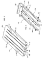
- Fig. 5 to 7 show a novel version according to the present invention of the sealing element 16.
- the through-holes 6a are defined by four continuous slits 17 formed in said sealing layer 16 from a front end face 18a.
- each continuous slit 17 of the sealing layer 16 has mutually equidistant circular apertures 16a which define said through-holes 6a.
- Each circular aperture 16a is formed on the holding layer 16 and along the continuous slit 17 so as to be aligned with a corresponding seat 3 formed in the body of the connector 1 when the sealing layer 16 is mounted in the final position thereof.
- the circular apertures 16a of two adjacent continuous slits 17 are mutually offset.
- the continuous slits 17 extend from the front end face 18a and are interrupted before reaching the rear end face 18b of the sealing layer 16.
- the sealing layer 16 is provided with one or more longitudinal portions of reduced thickness formed in said sealing layer 16 from at least one end face of the sealing layer 16, in such a way that the sealing layer 16 can be inserted into the connector body 2 by using the end face of the sealing layer 16 as the front face in the sliding movement, in such a way that the longitudinal portions of the sealing layer 16 are cut off by the conductors 5 and engage slidingly around the conductors 5 until the final mounting position is reached.
- the reduced thickness of the longitudinal portions with respect to the overall size of the sealing layer 16 makes it possible for the conductors 5 to cut the material easily, in such a way that the sealing layer 16 can slide easily on the conductors 5.
- Fig. 6 shows a plastics material support body 19 suitable for rigidifying the sealing element 16.
- Fig. 7 shows the assembled state of the sealing element 16 and the bearing body 19. Aside from rigidifying the sealing element 16, the presence of the bearing body 19 facilitates the operations of inserting the sealing element 16 into the guide passage 20 (see Fig. 8 ) formed in the body 2 of the connector 1.
- the support body 19 is of a fork shape comprising three longitudinal arms 19b which protrude in a projection from a grip portion 19a.
- the three arms 19b are arranged so as not to interfere with the pre-assembled conductors 5 in the connector 1 during the insertion of the sealing element 16 into the guide passage 20 formed in the connector body 2.
- fixing elements 19c in the form of pins can be seen on the support body 19, and are provided on the longitudinal arms 19b and suitable for fixing and holding in place the sealing layer 16 on the support body 19.
- each of the two end arms 19b of the support body 19 has two teeth 19d, protruding radially outwards from the end arms 19b and suitable for engaging with a respective longitudinal guide groove formed in the guide passage 20 formed in the body 2 of the connector 1, so as to facilitate the sliding mounting of the sealing element 16 fitted on the support body 19.
- the sliding layer 16 supported by the bearing body 19 is moved parallel to the plane thereof.
- the end face 18a of the sealing layer 16 is used as the front face in the sliding movement.
- the sealing layer 16 can be inserted into the body 2 of the connector 1 after said terminal contacts 4 along with the respective conductors 5 have been received in the body 2 of the connector, causing the slits 17 of the sealing layer 16 or the portions of reduced thickness to engage slidingly around the conductors 5 until a final mounting position is reached.
- the connector 1 further provides a cover element 7 comprising a plurality of through-holes 7a into which the conductors 5 are inserted.
- the cover element 7 is positioned above the body 2 of the connector prior to the operation of inserting the terminal contacts 4, in such a way that the through-holes 7a are positioned in a manner corresponding to the corresponding seats 3 formed in the body 2 of the connector 1. After the sliding insertion of the sealing element 16, to improve the sealing the cover element 7 is displaced from the raised rest position thereof into the lowered operational position thereof in which it compresses the sealing element 16.
- Fig. 8 to 11 show various steps of the operation of assembling the electrical connector 1.
- Fig. 8 relates to the step of wiring the conductors inside the body 2 of the connector.
- Each connector 5 is positioned in a manner corresponding to a through-aperture 7a and inserted into the body 2 of the connector until it reaches the corresponding seat 3 formed in the base portion of the connector 1.
- Fig. 9 relates to the state at the end of the wiring operation
- Fig. 10 shows the connector 1 at the end of the operation of slidingly inserting the sealing layer 16 borne by the support body 19.
- Fig. 11 shows the connector 1 at the end of the assembly operations, in which the cover element 7 has been brought into the lowered operative position thereof (in the direction shown by the arrow) in which it compresses the sealing element 16.
- the sealing element 16 is made of gel or silicone (for example the gel marketed as GT-4201-T3.0-SHEET and produced by DOW CORNING).
- the gel has self-adhering and self-healing properties such that, after the sealing element 16 has been inserted into the body 2 of the connector 1, said properties tend to bring together and close the slits 17 and the circular apertures 16a previously deformed by the sliding travel around the preassembled conductors 5 in the connector 1.
- the cover element 7 no longer requires the presence of the plugs 7b, since the self-adhering and self-healing properties ensure the closure of the circular apertures 16a which are not engaged by a respective conductor 5. Further, the compression of the sealing element 16 brought about by the cover element 7 promotes the closure of the slits 17, ensuring the sealing.
- a radial sealing gasket 21 can further be seen, provided in the body 2 of the connector 1 so as to guarantee the sealing between the two counter pieces.
- the present invention further relates to a process for assembling an electrical connector of the type stated previously, the process providing the steps of:
- the sealing element is inserted into the connector after the wiring step, resulting in the wiring operation itself being facilitated even for conductors having a diameter of reduced dimensions. Further, different cycles of inserting/removing the conductors can be implemented without reducing the sealing performance of the sealing layer, which may be removed from the connector previously before carrying out the new operations of inserting/removing the conductors. Finally, with the connector according to the present invention, the terminal contacts of the conductors are prevented from being "soiled" by free gel particles, since the sealing layer only comes into contact with the part of the conductor covered by the protective sheath, and not with the contact terminals.
Landscapes
- Engineering & Computer Science (AREA)
- Manufacturing & Machinery (AREA)
- Connector Housings Or Holding Contact Members (AREA)
- Manufacturing Of Electrical Connectors (AREA)
Description
- The present invention relates to an electrical connector comprising a connector body including a plurality of seats for a plurality of terminal contacts each associated with a respective conductor, and at least one sealing element in the form of a layer of resiliently deformable, electrically insulating material, received within the body of the connector in a plane transverse to the conductors associated with said terminal contacts, so as to provide a seal around the conductors.
- Referring to
Fig. 1 to 4 , which relate to the prior art, an electrical connector is denoted as a whole byreference numeral 1. Theconnector 1 comprises aconnector body 2 which provides in the interior thereof, and on the base portion 2a thereof, a plurality ofseats 3 which can each receive in the interior thereof aterminal contact 4 associated with arespective conductor 5. - The
connector 1 further comprises a sealing element 6 (seeFig. 2 ) in the form of a layer of resiliently deformable, electrically insulating material. The sealinglayer 6 is received within thebody 2 of theconnector 1 and similarly has a plurality of through-holes 6a for sealing engagement of theconductors 5 associated with saidterminal contacts 4. Naturally, the through-holes 6a of the sealinglayer 6 are arranged in such a way that, when it is assembled with theconnector 1, they are positioned in a manner corresponding to therespective seats 3. - The
connector 1 may further comprise a cover element 7 (seeFig. 3 ) which similarly has through-apertures 7a arranged in such a way that, when it is assembled with theconnector 1, they are likewise positioned in a manner corresponding to therespective seats 3 and the through-holes 6a. Thecover element 7 further providesplugs 7b, arranged in some of theapertures 7a, for closing theseats 3 which do not need to accommodate a respectiveterminal contact 4. Thecover element 7 further comprises mountingfeet 7d for guiding the positioning of the element inside thebody 2 of the connector. Thecover element 7 may thus be seen as a "map" which the technician uses for the wiring. - Referring to
Fig. 4 , it may be noted that the connector is assembled by positioning thesealing element 6 on the base portion 2a in such a way that the through-holes 6a are arranged above therespective seats 3. Subsequently, thecover element 7 is inserted by arranging it above thesealing element 6, and finally this is followed by the wiring operation of inserting theterminal contacts 4 into the through-apertures 7a, by passing them through thesealing layer 6, until theseats 3 are finally reached, theconductor 5 thus being inserted into theconnector 1. - Finally, the
body 2 of theconnector 1 comprises a lever-operatedlocking element 2b which activatesfixing bars 2c to engage and secure theconnector 1 to a counter piece (not shown in the drawings). By displacing thelever 2b from an open position to a covering position, the connector is coupled to the counter piece. -
DE 4015793 discloses an electrical connector according to the preamble ofclaim 1. - The object of the present invention is to provide a sealed electrical connector of the type specified above, which is of a relatively simple and cheap construction, and which makes it possible to provide a sealing system with a small (or tending to zero) force for inserting the terminal through the sealing element.
- A further object of the present invention is to provide an electrical connector which preserves all of the advantages of the known solution, and which makes it possible to provide different cycles of inserting/removing the contacts without compromising the simplicity of manufacture and the reliability of the sealing.
- According to the present invention, this object is achieved by an electrical connector having the features stated above and further characterised in that the connector body is provided with a guide passage for slidingly mounting the sealing layer within the connector body, by moving the sealing layer parallel to the plane thereof in such a way that the sealing layer can be inserted into the connector body after said terminal contacts along with the respective conductors have been received in the connector body, and in such a way that the sealing layer engages slidingly around the conductors until a final mounting position is reached.
- In the preferred embodiment, the sealing layer is provided with a plurality of through-holes defined by one or more continuous slits formed in said sealing layer from an end face of the sealing layer, in such a way that the sealing layer can be inserted into the connector body by using the end face of the sealing layer as a front face in the sliding movement, in such a way that the slits in the sealing layer engage slidingly around the conductors until the final mounting position is reached.
- In a variant, the sealing layer is provided with one or more longitudinal portions of reduced thickness formed in said sealing layer from at least one end face of the sealing layer, in such a way that the sealing layer can be inserted into the connector body by using the end face of the sealing layer as the front face in the sliding movement, in such a way that the longitudinal portions of the sealing layer are cut off by the conductors and engage slidingly around the conductors until the final mounting position is reached.
- In the aforementioned preferred embodiment, each continuous slit of the sealing layer has circular mutually equidistant apertures defining said through-holes, and each circular aperture is formed in the sealing layer and along the continuous slit so as to be aligned with a corresponding seat formed in the connector body when the sealing layer is mounted in the final position thereof.
- Still referring to said preferred embodiment, the continuous slits extend from the front end face and are interrupted before reaching the rear end face of the sealing layer.
- Preferably, a plastics material support body, suitable for rigidifying the sealing element and facilitating the operations for inserting the sealing element into the guide passage formed in the connector body, is associated with the sealing element. The support body of the sealing element is of a fork shape comprising a plurality of longitudinal arms which protrude in a projection from a grip portion. The arms are arranged so as not to interfere with the pre-assembled conductors in the connector during the insertion of the sealing element into the guide passage formed in the connector body.
- In a preferred embodiment, the support body has fixing elements provided on the longitudinal arms thereof for fixing and holding in place the sealing layer on the support body.
- Preferably, each of the two end arms of the support body has a plurality of radially protruding teeth. The teeth are suitable for engaging with a respective longitudinal guide groove formed in the guide passage formed in the connector body, so as to facilitate the sliding mounting of the sealing element fitted on the support body.
- In one embodiment, the connector further comprises a cover element comprising a plurality of through-holes into which the conductors are inserted. The cover element is positioned above the body of the connector prior to the operation of inserting the terminal contacts, in such a way that the through-holes are positioned in a manner corresponding to the corresponding seats formed in the connector body. After the sliding insertion of the sealing element, to improve the sealing the cover element is brought from the raised rest position thereof into the lowered operational position thereof in which it compresses the sealing element.
- Preferably, the sealing element is made of gel or silicone, and the material has self-adhering and self-healing properties such that, after the sealing element has been inserted into the connector body, the properties tend to bring together and close the slits and the circular apertures previously deformed by the sliding travel around the preassembled conductors in the connector.
- The present invention further relates to a process for assembling an electrical connector of the type stated above, comprising the steps of:
- providing, in the connector body, a guide passage for slidingly mounting the sealing layer inside the connector body by moving the sealing layer parallel to the plane thereof,
- inserting the terminal contacts along with the respective conductors into the seats formed in the body of the connector, and
- slidingly mounting the sealing layer in the body of the connector, causing the slits of the sealing layer to engage slidingly around the conductors until a final mounting position is reached,
- Preferably, the sealing layer is provided with a plurality of through-holes defined by one or more continuous slits formed in said sealing layer from an end face of the sealing layer, in such a way that the sealing layer can be inserted into the connector body by using the end face of the sealing layer as a front face in the sliding movement, in such a way that the slits in the sealing layer engage slidingly around the conductors until the final mounting position is reached.
- Alternatively, the sealing layer is provided with one or more longitudinal portions of reduced thickness formed in said sealing layer from at least one end face of the sealing layer, in such a way that the sealing layer can be inserted into the connector body by using the end face of the sealing layer as the front face in the sliding movement, in such a way that the longitudinal portions of the sealing layer are cut off by the conductors and engage slidingly around the conductors until the final mounting position is reached.
- Further, it is possible to provide the step of providing a cover element comprising a plurality of through-holes into which the conductors are inserted, the cover element being positioned above the body of the connector prior to the operation of inserting the terminal contacts, in such a way that the through-holes are positioned in a manner corresponding to the corresponding seats formed in the connector body, and that after the sliding insertion of the sealing element, to improve the sealing a step of activating the cover element is provided in which it is brought from the raised rest position thereof into the lowered operational position thereof in which it compresses the sealing element.
- By virtue of the features stated above, on the one hand the connector according to the invention is made simple and cheap to produce, and on the other hand, it guarantees secure and reliable sealing. The formation thereof further makes it possible to prevent the terminal contacts of the conductors from being soiled by gel particles, since the gel sealing layer does not come into contact therewith, being mounted on the connector after the terminal contacts have already been assembled in the respective seats.
- One of the advantages which can be achieved with a connector according to the invention is that it is no longer necessary to provide cover elements for insertion into the seats which are left free by the conductors, since the self-adhering features of the gel itself guarantee the sealing.
- Further features and advantages of the invention may be taken from the following description with reference to the appended drawings, which are provided purely by way of non-limiting example and in which:
-
Fig. 1 to 4 , relating to the prior art, were described previously, -
Fig. 5 to 7 are perspective views of the sealing element and the support element according to the present invention when decoupled and when coupled, -
Fig. 8 to 11 are perspective views of a connector according to the present invention, in various states of assembly, and -
Fig. 12 is a sectional view of the connector according to the present invention, corresponding to the state of assembly shown inFig. 11 . - The following description illustrates various specific details intended to provide a thorough understanding of the embodiments. The embodiments may be implemented without one or more of the specified details, or using other methods, components, materials etc. In other cases, known constructions, constructional details, materials and operations are not shown or described in detail, since they may be implemented in any known manner and also since, when taken in isolation, they are not within the scope of the present invention.
- In
Fig. 5 to 12 , the common parts which were described above with reference to the embodiment shown inFig. 1-4 will be denoted by the same reference numerals in the following, whilst the added or modified parts will be given a different reference numeral. -
Fig. 5 to 7 show a novel version according to the present invention of the sealingelement 16. - Referring to
Fig. 5 to 7 , in the sealing element according to the present invention, the through-holes 6a are defined by fourcontinuous slits 17 formed in said sealinglayer 16 from afront end face 18a. - In particular, each
continuous slit 17 of thesealing layer 16 has mutually equidistantcircular apertures 16a which define said through-holes 6a. Eachcircular aperture 16a is formed on theholding layer 16 and along thecontinuous slit 17 so as to be aligned with acorresponding seat 3 formed in the body of theconnector 1 when thesealing layer 16 is mounted in the final position thereof. In the embodiment shown in the drawings, thecircular apertures 16a of two adjacentcontinuous slits 17 are mutually offset. - In the embodiment shown in the drawings, the
continuous slits 17 extend from thefront end face 18a and are interrupted before reaching therear end face 18b of thesealing layer 16. - In a different embodiment, not shown in the drawings, the
sealing layer 16 is provided with one or more longitudinal portions of reduced thickness formed in saidsealing layer 16 from at least one end face of thesealing layer 16, in such a way that thesealing layer 16 can be inserted into theconnector body 2 by using the end face of thesealing layer 16 as the front face in the sliding movement, in such a way that the longitudinal portions of thesealing layer 16 are cut off by theconductors 5 and engage slidingly around theconductors 5 until the final mounting position is reached. - The reduced thickness of the longitudinal portions with respect to the overall size of the
sealing layer 16 makes it possible for theconductors 5 to cut the material easily, in such a way that thesealing layer 16 can slide easily on theconductors 5. -
Fig. 6 shows a plasticsmaterial support body 19 suitable for rigidifying thesealing element 16.Fig. 7 shows the assembled state of thesealing element 16 and the bearingbody 19. Aside from rigidifying thesealing element 16, the presence of the bearingbody 19 facilitates the operations of inserting thesealing element 16 into the guide passage 20 (seeFig. 8 ) formed in thebody 2 of theconnector 1. - In the example of the embodiment shown in the drawings, the
support body 19 is of a fork shape comprising threelongitudinal arms 19b which protrude in a projection from agrip portion 19a. The threearms 19b are arranged so as not to interfere with thepre-assembled conductors 5 in theconnector 1 during the insertion of the sealingelement 16 into theguide passage 20 formed in theconnector body 2. - In
Fig. 6 , fixingelements 19c in the form of pins can be seen on thesupport body 19, and are provided on thelongitudinal arms 19b and suitable for fixing and holding in place thesealing layer 16 on thesupport body 19. - Further, each of the two
end arms 19b of thesupport body 19 has twoteeth 19d, protruding radially outwards from theend arms 19b and suitable for engaging with a respective longitudinal guide groove formed in theguide passage 20 formed in thebody 2 of theconnector 1, so as to facilitate the sliding mounting of the sealingelement 16 fitted on thesupport body 19. - To mount the
sealing layer 16 slidingly in thebody 2 of theconnector 1, the slidinglayer 16 supported by the bearingbody 19 is moved parallel to the plane thereof. Theend face 18a of thesealing layer 16 is used as the front face in the sliding movement. - By virtue of the shaping of the
sealing layer 16 and the bearingbody 19, thesealing layer 16 can be inserted into thebody 2 of theconnector 1 after saidterminal contacts 4 along with therespective conductors 5 have been received in thebody 2 of the connector, causing theslits 17 of thesealing layer 16 or the portions of reduced thickness to engage slidingly around theconductors 5 until a final mounting position is reached. - The
connector 1 further provides acover element 7 comprising a plurality of through-holes 7a into which theconductors 5 are inserted. Thecover element 7 is positioned above thebody 2 of the connector prior to the operation of inserting theterminal contacts 4, in such a way that the through-holes 7a are positioned in a manner corresponding to thecorresponding seats 3 formed in thebody 2 of theconnector 1. After the sliding insertion of the sealingelement 16, to improve the sealing thecover element 7 is displaced from the raised rest position thereof into the lowered operational position thereof in which it compresses the sealingelement 16. -
Fig. 8 to 11 show various steps of the operation of assembling theelectrical connector 1. In particular,Fig. 8 relates to the step of wiring the conductors inside thebody 2 of the connector. Eachconnector 5 is positioned in a manner corresponding to a through-aperture 7a and inserted into thebody 2 of the connector until it reaches thecorresponding seat 3 formed in the base portion of theconnector 1.Fig. 9 relates to the state at the end of the wiring operation, whilstFig. 10 shows theconnector 1 at the end of the operation of slidingly inserting thesealing layer 16 borne by thesupport body 19. Finally,Fig. 11 shows theconnector 1 at the end of the assembly operations, in which thecover element 7 has been brought into the lowered operative position thereof (in the direction shown by the arrow) in which it compresses the sealingelement 16. - The sealing
element 16 is made of gel or silicone (for example the gel marketed as GT-4201-T3.0-SHEET and produced by DOW CORNING). - The gel has self-adhering and self-healing properties such that, after the sealing
element 16 has been inserted into thebody 2 of theconnector 1, said properties tend to bring together and close theslits 17 and thecircular apertures 16a previously deformed by the sliding travel around thepreassembled conductors 5 in theconnector 1. - In the embodiment shown, the
cover element 7 no longer requires the presence of theplugs 7b, since the self-adhering and self-healing properties ensure the closure of thecircular apertures 16a which are not engaged by arespective conductor 5. Further, the compression of the sealingelement 16 brought about by thecover element 7 promotes the closure of theslits 17, ensuring the sealing. - In
Fig. 12 , aradial sealing gasket 21 can further be seen, provided in thebody 2 of theconnector 1 so as to guarantee the sealing between the two counter pieces. - The present invention further relates to a process for assembling an electrical connector of the type stated previously, the process providing the steps of:
- providing, in the
connector body 2, aguide passage 20 for slidingly mounting thesealing layer 16 inside theconnector body 2, by moving thesealing layer 16 parallel to the plane thereof, - inserting the
terminal contacts 4 along with therespective conductors 5 into theseats 3 formed in thebody 2 of the connector, and - slidingly mounting the
sealing layer 16 in the body of the connector, causing theslits 17 of thesealing layer 16 to engage slidingly around theconductors 5 until a final mounting position is reached, - The sealing element is inserted into the connector after the wiring step, resulting in the wiring operation itself being facilitated even for conductors having a diameter of reduced dimensions. Further, different cycles of inserting/removing the conductors can be implemented without reducing the sealing performance of the sealing layer, which may be removed from the connector previously before carrying out the new operations of inserting/removing the conductors. Finally, with the connector according to the present invention, the terminal contacts of the conductors are prevented from being "soiled" by free gel particles, since the sealing layer only comes into contact with the part of the conductor covered by the protective sheath, and not with the contact terminals.
- Of course, without prejudice to the principle behind the invention, the construction details and the embodiments can be varied considerably from what has been described and illustrated purely by way of example, without going beyond the scope of the invention as a result of this.
-
- 1:
- electrical connector
- 2:
- connector body
- 2a:
- on the base portion
- 2b:
- lever-operated locking element
- 2c:
- fixing bars
- 3:
- seats for receiving the terminal contacts
- 4:
- terminal contacts
- 5:
- conductors
- 6:
- sealing element
- 6a:
- through-holes
- 7:
- cover element
- 7a:
- through-holes
- 7b:
- plugs
- 7d:
- mounting feet
- 16:
- sealing layer or element
- 16a:
- circular aperture
- 17:
- continuous slit
- 18a:
- front end face
- 18b:
- rear end face
- 19:
- support body
- 19a:
- grip portion
- 19b:
- longitudinal arms
- 19c:
- fixing elements
- 19d:
- protruding teeth
- 20:
- guide passage
- 21:
- radial sealing gasket
in such a way that the sealing layer engages slidingly around them until a final mounting position is reached.
Claims (16)
- Electrical connector (1) comprising a connector body (2) including a plurality of seats (3) for a plurality of terminal contacts (4) each associated with a respective conductor (5), and at least one sealing element (6) in the form of a layer of resiliently deformable, electrically insulating material, received in the body (2) of the connector in a plane transverse to the conductors (5) associated with said terminal contacts (4), so as to provide a seal around said conductors (5),
whereby said connector body (2) is provided with means for mounting the sealing layer (16) within the connector body (2),
in such a way that said sealing layer (16) can be inserted into the connector body (2) after said terminal contacts (4) along with the respective conductors (5) have been received in the connector body (2), and
in such a way that the sealing layer (16) engages slidingly around said conductors (5) until a final mounting position is reached characterised in that said means is a guide passage (23) for slidingly mounting the sealing layer (16) within the connector body (2), by moving the sealing layer (16) parallel to the plane thereof. - Electrical connector according to claim 1, characterised in that said sealing layer (16) is provided with a plurality of through-holes (6a) defined by one or more continuous slits (17) formed in said sealing layer (16) from an end face (18a) of the sealing layer (16),
in such a way that said sealing layer (16) can be inserted into the connector body (2) by using said end face (18a) of the sealing layer (16) as a front face in the sliding movement, in such a way that said slits (17) in the sealing layer (16) engage slidingly around said conductors (5) until the final mounting position is reached. - Electrical connector according to claim 1, characterised in that said sealing layer (16) is provided with one or more longitudinal portions of reduced thickness formed in said sealing layer (16) from at least one end face (18a) of said sealing layer (16),
in such a way that said sealing layer (16) can be inserted into the connector body (2) by using said at least one end face (18a) of the sealing layer (16) as the front face in said sliding movement, in such a way that said longitudinal portions of the sealing layer (16) are cut off by the conductors (5) and engage slidingly around the conductors (5) until the final mounting position is reached. - Electrical connector according to claim 2, characterised in that each continuous slit (17) of said sealing layer has circular mutually equidistant apertures (16a) defining said through-holes (6a), and in that each circular aperture (16a) is formed in the sealing layer (16) and along the continuous slit (17) so as to be positioned in a manner corresponding to a seat (3) formed in the body of the connector when the sealing layer (16) is mounted in the final position thereof.
- Electrical connector according to either claim 2 or claim 4, characterised in that said continuous slits (17) extend from the front end face (18a) and are interrupted before reaching the rear end face (18b) of the sealing layer (16).
- Electrical connector according to any one of the preceding claims, characterised in that a plastics material support body (19), suitable for rigidifying the sealing element (16) and facilitating the operations for inserting the sealing element (16) into the guide passage (20) formed in the connector body (2), is associated with said sealing element (16).
- Electrical connector according to claim 6, characterised in that said support body (19) is of a fork shape comprising a plurality of longitudinal arms (19b) which protrude in a projection from a grip portion (19a), said arms (19b) being arranged so as not to interfere with said pre-assembled conductors (5) in the connector (1) during the insertion of the sealing element (16) into the guide passage (20) formed in the body (2) of the connector.
- Electrical connector according to claim 7, characterised in that said support body (19) has fixing elements (19c) provided on the longitudinal arms (19b) thereof, said fixing elements (19c) being suitable for fixing and holding in place said sealing layer (16) on the support body (19).
- Electrical connector according to either claim 7 or claim 8, characterised in that each of the two end arms (19b) of said support body (19) has a plurality of radially protruding teeth (19d), said teeth (19d) being suitable for engaging with a respective longitudinal guide groove formed in the guide passage (20) formed in the body (2) of the connector, so as to facilitate the sliding mounting of the sealing element (16) fitted on the support body (19).
- Electrical connector according to any one of the preceding claims, characterised in that said connector (1) further provides a cover element (7) comprising a plurality of through-holes (7a) into which said conductors (5) are inserted, said cover element (7) being positioned above the body (2) of the connector prior to the operation of inserting the terminal contacts (4), in such a way that the through-holes (7a) are positioned in a manner corresponding to the corresponding seats (3) formed in the body (2) of the connector, and in that after the sliding insertion of the sealing element (16), to improve the sealing the cover element (7) is displaced from the raised rest position thereof into the lowered operational position thereof in which it compresses the sealing element (16).
- Electrical connector according to any one of the preceding claims, characterised in that said sealing element (16) is made of gel or silicone.
- Electrical connector according to claim 11, characterised in that said gel has self-adhering and self-healing properties such that, after the sealing element (16) has been inserted into the body (2) of the connector, the properties tend to bring together and close the slits (17) and the circular apertures (16a) or the longitudinal portions of reduced thickness previously deformed by the sliding travel around the preassembled conductors (5) in the connector (1).
- Process for assembling an electrical connector, in which said electrical connector (1) comprises a connector body (2) including a plurality of seats (3) for a plurality of terminal contacts (4) each associated with a respective conductor (5), and at least one sealing element (6) in the form of a layer of resiliently deformable, electrically insulating material, received in the body (2) of the connector in a plane transverse to the conductors (5) associated with said terminal contacts (4), so as to provide a seal around said conductors (5)
characterised in that said process provides the steps of:- providing, in said connector body (2), a guide passage (20) for slidingly mounting the sealing layer (16) inside the connector body (2), by moving the sealing layer (16) parallel to the plane thereof,- inserting the terminal contacts (4) along with the respective conductors (5) into the seats (3) formed in the body (2) of the connector, and- slidingly mounting the sealing layer (16) in said body of the connector,in such a way that said sealing layer (16) can be inserted into the body (2) of the connector after said terminal contacts (4) along with the respective conductors (5) have been received in the body (2) of the connector, and
in such a way that the sealing layer (16) engages slidingly around the conductors (5) until a final mounting position is reached. - Process according to claim 13, characterised in that said sealing layer (16) is provided with a plurality of through-holes (6a) defined by one or more continuous slits (17) formed in said sealing layer (16) from an end face (18a) of said sealing layer (16),
in such a way that the sealing layer (16) can be inserted into the connector body (2) by using the end face (18a) of the sealing layer (16) as a front face in the sliding movement, in such a way that said slits (17) in the sealing layer (16) engage slidingly around said conductors (5) until the final mounting position is reached. - Process according to claim 13, characterised in that said sealing layer (16) is provided with one or more longitudinal portions of reduced thickness formed in said sealing layer (16) from at least one end face (18a) of the sealing layer (16),
in such a way that said sealing layer (16) can be inserted into the connector body (2) by using said at least one end face (18a) of the sealing layer (16) as the front face in said sliding movement, in such a way that said longitudinal portions of the sealing layer (16) are cut off by the conductors (5) and engage slidingly around the conductors (5) until the final mounting position is reached. - Process according to any one of claims 13 to 15, characterised in that it further provides the step of providing a cover element (7) comprising a plurality of through-holes (7a) into which said conductors (5) are inserted, said cover element (7) being positioned above the body (2) of the connector prior to the operation of inserting the terminal contacts (4), in such a way that the through-holes (7a) are positioned in a manner corresponding to the corresponding seats (3) formed in the body (2) of the connector,
and in that after the step of sliding insertion of the sealing element (16), to improve the sealing a step of activating the cover element (7) is provided, in which said cover element (7) is brought from the raised rest position thereof into the lowered operational position thereof in which it compresses the sealing element (16).
Applications Claiming Priority (1)
| Application Number | Priority Date | Filing Date | Title |
|---|---|---|---|
| IT000905A ITTO20120905A1 (en) | 2012-10-16 | 2012-10-16 | ELECTRIC CONNECTOR WITH SEALING ELEMENT AND PROCEDURE FOR ASSEMBLY |
Publications (2)
| Publication Number | Publication Date |
|---|---|
| EP2722935A1 EP2722935A1 (en) | 2014-04-23 |
| EP2722935B1 true EP2722935B1 (en) | 2015-04-22 |
Family
ID=47324299
Family Applications (1)
| Application Number | Title | Priority Date | Filing Date |
|---|---|---|---|
| EP20130187922 Active EP2722935B1 (en) | 2012-10-16 | 2013-10-09 | Electrical connector comprising a sealing element and assembly process |
Country Status (5)
| Country | Link |
|---|---|
| US (1) | US9136637B2 (en) |
| EP (1) | EP2722935B1 (en) |
| JP (1) | JP6227360B2 (en) |
| CN (1) | CN103730763B (en) |
| IT (1) | ITTO20120905A1 (en) |
Families Citing this family (12)
| Publication number | Priority date | Publication date | Assignee | Title |
|---|---|---|---|---|
| CN104025393B (en) * | 2011-10-24 | 2016-10-12 | 安达概念股份有限公司 | Controlled Impedance Cable Termination Using Compatible Interconnect Components |
| USRE47459E1 (en) * | 2011-10-24 | 2019-06-25 | Ardent Concepts, Inc. | Controlled-impedance cable termination using compliant interconnect elements |
| US9312639B2 (en) | 2014-04-15 | 2016-04-12 | Ardent Concepts, Inc. | Controlled-impedance cable termination with compensation for cable expansion and contraction |
| CN104752861B (en) * | 2015-04-07 | 2017-05-17 | 苏州源硕精密模具有限公司 | Easy-to-assemble PCB (printed circuit board) connector and assembling method of same |
| CN104752862B (en) * | 2015-04-07 | 2017-03-15 | 苏州源硕精密模具有限公司 | FPC connector for substrate terminal and the assemble method of the terminal |
| ITUA20164609A1 (en) * | 2016-06-23 | 2017-12-23 | Te Connectivity Germany Gmbh | Connection assembly comprising a sealing element for sealing a cable and a housing, and a method of producing a sealing element for a connection assembly |
| DE102016211372B4 (en) * | 2016-06-24 | 2018-06-07 | Robert Bosch Gmbh | Harness connector, method for producing a fluid-tight harness connector and auxiliary element for insertion into a harness connector |
| US10027051B1 (en) * | 2017-02-20 | 2018-07-17 | Robert Bosch Gmbh | Hybrid electrical connector |
| EP3396781B1 (en) * | 2017-04-26 | 2021-02-17 | Nexans | Electrical coupling part and method of manufacturing the coupling part |
| RU2020134237A (en) | 2018-04-06 | 2022-05-06 | Фишер Коннекторс Холдинг С.А. | MULTIPLE CONNECTOR |
| EP3756248A1 (en) | 2018-04-06 | 2020-12-30 | Fischer Connectors Holding S.A. | Multipolar connector |
| CN116191168B (en) * | 2022-12-30 | 2026-02-10 | 华勤技术股份有限公司 | A method and apparatus for dispensing adhesive into connectors. |
Family Cites Families (16)
| Publication number | Priority date | Publication date | Assignee | Title |
|---|---|---|---|---|
| US4993964A (en) * | 1989-04-18 | 1991-02-19 | Martin Marietta Corporation | Electrical connector environmental sealing plug |
| JPH067584Y2 (en) * | 1989-05-31 | 1994-02-23 | 矢崎総業株式会社 | Waterproof connector |
| JPH0644046U (en) * | 1992-11-10 | 1994-06-10 | 日本エー・エム・ピー株式会社 | Waterproof connector |
| US5788519A (en) * | 1995-05-02 | 1998-08-04 | Yazaki Corporation | Waterproof grounding connector and method of assembling same |
| JP3388573B2 (en) * | 1997-04-09 | 2003-03-24 | 矢崎総業株式会社 | Waterproof connector |
| JP3566541B2 (en) * | 1998-03-31 | 2004-09-15 | 矢崎総業株式会社 | Waterproof connector and waterproofing method |
| DE69939206D1 (en) * | 1998-06-08 | 2008-09-11 | Sumitomo Wiring Systems | WATERPROOF CONNECTOR |
| US6155850A (en) * | 1998-09-25 | 2000-12-05 | The Whitaker Corporation | Cam slide electrical connector |
| JP2001266998A (en) * | 2000-03-16 | 2001-09-28 | Yazaki Corp | Waterproof connector |
| JP2003068392A (en) * | 2001-08-29 | 2003-03-07 | Tyco Electronics Amp Kk | Waterproof connector |
| DE102006032575B3 (en) | 2006-07-12 | 2008-02-14 | Yazaki Europe Ltd., Hemel Hempstead | Connectors |
| US7914309B2 (en) * | 2007-03-20 | 2011-03-29 | Fci | Electrical connector comprising a mat seal and a ramp system for compressing the mat seal |
| US7686647B1 (en) * | 2008-10-21 | 2010-03-30 | J.S.T. Corporation | Terminal assembly and sealed electrical connector |
| ATE515080T1 (en) * | 2009-03-12 | 2011-07-15 | Tyco Electronics Amp Gmbh | ELECTRICAL CONNECTOR |
| JP5656122B2 (en) * | 2011-06-06 | 2015-01-21 | 住友電装株式会社 | connector |
| CN202423688U (en) * | 2011-11-29 | 2012-09-05 | 德尔福派克电气系统有限公司 | Waterproof connector |
-
2012
- 2012-10-16 IT IT000905A patent/ITTO20120905A1/en unknown
-
2013
- 2013-10-03 JP JP2013208371A patent/JP6227360B2/en active Active
- 2013-10-07 US US14/047,374 patent/US9136637B2/en active Active
- 2013-10-09 EP EP20130187922 patent/EP2722935B1/en active Active
- 2013-10-16 CN CN201310485093.7A patent/CN103730763B/en active Active
Also Published As
| Publication number | Publication date |
|---|---|
| CN103730763A (en) | 2014-04-16 |
| US20140106589A1 (en) | 2014-04-17 |
| JP6227360B2 (en) | 2017-11-08 |
| EP2722935A1 (en) | 2014-04-23 |
| CN103730763B (en) | 2017-04-12 |
| JP2014082207A (en) | 2014-05-08 |
| ITTO20120905A1 (en) | 2014-04-17 |
| US9136637B2 (en) | 2015-09-15 |
Similar Documents
| Publication | Publication Date | Title |
|---|---|---|
| US9136637B2 (en) | Electrical connector comprising a sealing element and assembly process | |
| US11664629B2 (en) | Assembly comprising a connector and a cable | |
| US11362466B2 (en) | Electrical connector and connector assembly | |
| CA2669251C (en) | A connector | |
| EP2642598B1 (en) | Electric terminal | |
| US11411352B2 (en) | Connector for automotive applications | |
| US12100915B2 (en) | Shielded electrical connector for automotive applications and method of assembling thereof | |
| KR20110004308A (en) | Elbow coaxial electrical connectors and methods of assembling such connectors | |
| EP3783754A1 (en) | Connector for automotive applications | |
| JP6619812B2 (en) | Plug connector for flexible conductor membrane | |
| JP2013524435A (en) | Cable organizer for electrical connectors | |
| JP2015536537A (en) | Plug-in connector with insulating parts | |
| EP2894725B1 (en) | Electrical connector | |
| EP2768087A1 (en) | Shield shell and shield connector | |
| EP3376597B1 (en) | Wire to wire connector and method for providing the wire to wire connector | |
| US20140374545A1 (en) | Housing and wire holder thereof | |
| JP2010140706A (en) | Shielded connector and shielding device | |
| CN120222096A (en) | High voltage shielded electrical connector | |
| HK1249666B (en) | Housing for a plug-in connection | |
| WO2014096882A1 (en) | Electrical high power connector assembly |
Legal Events
| Date | Code | Title | Description |
|---|---|---|---|
| PUAI | Public reference made under article 153(3) epc to a published international application that has entered the european phase |
Free format text: ORIGINAL CODE: 0009012 |
|
| AK | Designated contracting states |
Kind code of ref document: A1 Designated state(s): AL AT BE BG CH CY CZ DE DK EE ES FI FR GB GR HR HU IE IS IT LI LT LU LV MC MK MT NL NO PL PT RO RS SE SI SK SM TR |
|
| AX | Request for extension of the european patent |
Extension state: BA ME |
|
| GRAP | Despatch of communication of intention to grant a patent |
Free format text: ORIGINAL CODE: EPIDOSNIGR1 |
|
| 17P | Request for examination filed |
Effective date: 20141017 |
|
| RBV | Designated contracting states (corrected) |
Designated state(s): AL AT BE BG CH CY CZ DE DK EE ES FI FR GB GR HR HU IE IS IT LI LT LU LV MC MK MT NL NO PL PT RO RS SE SI SK SM TR |
|
| RIC1 | Information provided on ipc code assigned before grant |
Ipc: H01R 43/16 20060101ALI20141105BHEP Ipc: H01R 13/52 20060101AFI20141105BHEP Ipc: H01R 13/436 20060101ALN20141105BHEP |
|
| INTG | Intention to grant announced |
Effective date: 20141119 |
|
| GRAS | Grant fee paid |
Free format text: ORIGINAL CODE: EPIDOSNIGR3 |
|
| GRAA | (expected) grant |
Free format text: ORIGINAL CODE: 0009210 |
|
| AK | Designated contracting states |
Kind code of ref document: B1 Designated state(s): AL AT BE BG CH CY CZ DE DK EE ES FI FR GB GR HR HU IE IS IT LI LT LU LV MC MK MT NL NO PL PT RO RS SE SI SK SM TR |
|
| REG | Reference to a national code |
Ref country code: GB Ref legal event code: FG4D |
|
| REG | Reference to a national code |
Ref country code: CH Ref legal event code: EP |
|
| REG | Reference to a national code |
Ref country code: AT Ref legal event code: REF Ref document number: 723747 Country of ref document: AT Kind code of ref document: T Effective date: 20150515 |
|
| REG | Reference to a national code |
Ref country code: IE Ref legal event code: FG4D |
|
| REG | Reference to a national code |
Ref country code: DE Ref legal event code: R096 Ref document number: 602013001562 Country of ref document: DE Effective date: 20150603 |
|
| REG | Reference to a national code |
Ref country code: NL Ref legal event code: VDEP Effective date: 20150422 |
|
| REG | Reference to a national code |
Ref country code: AT Ref legal event code: MK05 Ref document number: 723747 Country of ref document: AT Kind code of ref document: T Effective date: 20150422 |
|
| REG | Reference to a national code |
Ref country code: LT Ref legal event code: MG4D |
|
| PG25 | Lapsed in a contracting state [announced via postgrant information from national office to epo] |
Ref country code: NL Free format text: LAPSE BECAUSE OF FAILURE TO SUBMIT A TRANSLATION OF THE DESCRIPTION OR TO PAY THE FEE WITHIN THE PRESCRIBED TIME-LIMIT Effective date: 20150422 |
|
| REG | Reference to a national code |
Ref country code: FR Ref legal event code: PLFP Year of fee payment: 3 |
|
| PG25 | Lapsed in a contracting state [announced via postgrant information from national office to epo] |
Ref country code: HR Free format text: LAPSE BECAUSE OF FAILURE TO SUBMIT A TRANSLATION OF THE DESCRIPTION OR TO PAY THE FEE WITHIN THE PRESCRIBED TIME-LIMIT Effective date: 20150422 Ref country code: PT Free format text: LAPSE BECAUSE OF FAILURE TO SUBMIT A TRANSLATION OF THE DESCRIPTION OR TO PAY THE FEE WITHIN THE PRESCRIBED TIME-LIMIT Effective date: 20150824 Ref country code: LT Free format text: LAPSE BECAUSE OF FAILURE TO SUBMIT A TRANSLATION OF THE DESCRIPTION OR TO PAY THE FEE WITHIN THE PRESCRIBED TIME-LIMIT Effective date: 20150422 Ref country code: FI Free format text: LAPSE BECAUSE OF FAILURE TO SUBMIT A TRANSLATION OF THE DESCRIPTION OR TO PAY THE FEE WITHIN THE PRESCRIBED TIME-LIMIT Effective date: 20150422 Ref country code: ES Free format text: LAPSE BECAUSE OF FAILURE TO SUBMIT A TRANSLATION OF THE DESCRIPTION OR TO PAY THE FEE WITHIN THE PRESCRIBED TIME-LIMIT Effective date: 20150422 Ref country code: NO Free format text: LAPSE BECAUSE OF FAILURE TO SUBMIT A TRANSLATION OF THE DESCRIPTION OR TO PAY THE FEE WITHIN THE PRESCRIBED TIME-LIMIT Effective date: 20150722 |
|
| PG25 | Lapsed in a contracting state [announced via postgrant information from national office to epo] |
Ref country code: IS Free format text: LAPSE BECAUSE OF FAILURE TO SUBMIT A TRANSLATION OF THE DESCRIPTION OR TO PAY THE FEE WITHIN THE PRESCRIBED TIME-LIMIT Effective date: 20150822 Ref country code: GR Free format text: LAPSE BECAUSE OF FAILURE TO SUBMIT A TRANSLATION OF THE DESCRIPTION OR TO PAY THE FEE WITHIN THE PRESCRIBED TIME-LIMIT Effective date: 20150723 Ref country code: RS Free format text: LAPSE BECAUSE OF FAILURE TO SUBMIT A TRANSLATION OF THE DESCRIPTION OR TO PAY THE FEE WITHIN THE PRESCRIBED TIME-LIMIT Effective date: 20150422 Ref country code: AT Free format text: LAPSE BECAUSE OF FAILURE TO SUBMIT A TRANSLATION OF THE DESCRIPTION OR TO PAY THE FEE WITHIN THE PRESCRIBED TIME-LIMIT Effective date: 20150422 Ref country code: LV Free format text: LAPSE BECAUSE OF FAILURE TO SUBMIT A TRANSLATION OF THE DESCRIPTION OR TO PAY THE FEE WITHIN THE PRESCRIBED TIME-LIMIT Effective date: 20150422 |
|
| REG | Reference to a national code |
Ref country code: DE Ref legal event code: R097 Ref document number: 602013001562 Country of ref document: DE |
|
| PG25 | Lapsed in a contracting state [announced via postgrant information from national office to epo] |
Ref country code: EE Free format text: LAPSE BECAUSE OF FAILURE TO SUBMIT A TRANSLATION OF THE DESCRIPTION OR TO PAY THE FEE WITHIN THE PRESCRIBED TIME-LIMIT Effective date: 20150422 Ref country code: DK Free format text: LAPSE BECAUSE OF FAILURE TO SUBMIT A TRANSLATION OF THE DESCRIPTION OR TO PAY THE FEE WITHIN THE PRESCRIBED TIME-LIMIT Effective date: 20150422 |
|
| PLBE | No opposition filed within time limit |
Free format text: ORIGINAL CODE: 0009261 |
|
| STAA | Information on the status of an ep patent application or granted ep patent |
Free format text: STATUS: NO OPPOSITION FILED WITHIN TIME LIMIT |
|
| PG25 | Lapsed in a contracting state [announced via postgrant information from national office to epo] |
Ref country code: CZ Free format text: LAPSE BECAUSE OF FAILURE TO SUBMIT A TRANSLATION OF THE DESCRIPTION OR TO PAY THE FEE WITHIN THE PRESCRIBED TIME-LIMIT Effective date: 20150422 Ref country code: SK Free format text: LAPSE BECAUSE OF FAILURE TO SUBMIT A TRANSLATION OF THE DESCRIPTION OR TO PAY THE FEE WITHIN THE PRESCRIBED TIME-LIMIT Effective date: 20150422 Ref country code: PL Free format text: LAPSE BECAUSE OF FAILURE TO SUBMIT A TRANSLATION OF THE DESCRIPTION OR TO PAY THE FEE WITHIN THE PRESCRIBED TIME-LIMIT Effective date: 20150422 Ref country code: RO Free format text: LAPSE BECAUSE OF NON-PAYMENT OF DUE FEES Effective date: 20150422 |
|
| 26N | No opposition filed |
Effective date: 20160125 |
|
| PG25 | Lapsed in a contracting state [announced via postgrant information from national office to epo] |
Ref country code: SI Free format text: LAPSE BECAUSE OF FAILURE TO SUBMIT A TRANSLATION OF THE DESCRIPTION OR TO PAY THE FEE WITHIN THE PRESCRIBED TIME-LIMIT Effective date: 20150422 Ref country code: LU Free format text: LAPSE BECAUSE OF FAILURE TO SUBMIT A TRANSLATION OF THE DESCRIPTION OR TO PAY THE FEE WITHIN THE PRESCRIBED TIME-LIMIT Effective date: 20151009 |
|
| PG25 | Lapsed in a contracting state [announced via postgrant information from national office to epo] |
Ref country code: MC Free format text: LAPSE BECAUSE OF FAILURE TO SUBMIT A TRANSLATION OF THE DESCRIPTION OR TO PAY THE FEE WITHIN THE PRESCRIBED TIME-LIMIT Effective date: 20150422 |
|
| REG | Reference to a national code |
Ref country code: IE Ref legal event code: MM4A |
|
| PG25 | Lapsed in a contracting state [announced via postgrant information from national office to epo] |
Ref country code: BE Free format text: LAPSE BECAUSE OF FAILURE TO SUBMIT A TRANSLATION OF THE DESCRIPTION OR TO PAY THE FEE WITHIN THE PRESCRIBED TIME-LIMIT Effective date: 20150422 |
|
| REG | Reference to a national code |
Ref country code: FR Ref legal event code: PLFP Year of fee payment: 4 |
|
| PG25 | Lapsed in a contracting state [announced via postgrant information from national office to epo] |
Ref country code: IE Free format text: LAPSE BECAUSE OF NON-PAYMENT OF DUE FEES Effective date: 20151009 |
|
| PG25 | Lapsed in a contracting state [announced via postgrant information from national office to epo] |
Ref country code: HU Free format text: LAPSE BECAUSE OF FAILURE TO SUBMIT A TRANSLATION OF THE DESCRIPTION OR TO PAY THE FEE WITHIN THE PRESCRIBED TIME-LIMIT; INVALID AB INITIO Effective date: 20131009 Ref country code: BG Free format text: LAPSE BECAUSE OF FAILURE TO SUBMIT A TRANSLATION OF THE DESCRIPTION OR TO PAY THE FEE WITHIN THE PRESCRIBED TIME-LIMIT Effective date: 20150422 |
|
| REG | Reference to a national code |
Ref country code: CH Ref legal event code: PL |
|
| PG25 | Lapsed in a contracting state [announced via postgrant information from national office to epo] |
Ref country code: CY Free format text: LAPSE BECAUSE OF FAILURE TO SUBMIT A TRANSLATION OF THE DESCRIPTION OR TO PAY THE FEE WITHIN THE PRESCRIBED TIME-LIMIT Effective date: 20150422 Ref country code: SE Free format text: LAPSE BECAUSE OF FAILURE TO SUBMIT A TRANSLATION OF THE DESCRIPTION OR TO PAY THE FEE WITHIN THE PRESCRIBED TIME-LIMIT Effective date: 20150422 |
|
| PG25 | Lapsed in a contracting state [announced via postgrant information from national office to epo] |
Ref country code: CH Free format text: LAPSE BECAUSE OF NON-PAYMENT OF DUE FEES Effective date: 20161031 Ref country code: LI Free format text: LAPSE BECAUSE OF NON-PAYMENT OF DUE FEES Effective date: 20161031 |
|
| PG25 | Lapsed in a contracting state [announced via postgrant information from national office to epo] |
Ref country code: MT Free format text: LAPSE BECAUSE OF FAILURE TO SUBMIT A TRANSLATION OF THE DESCRIPTION OR TO PAY THE FEE WITHIN THE PRESCRIBED TIME-LIMIT Effective date: 20150422 |
|
| REG | Reference to a national code |
Ref country code: FR Ref legal event code: PLFP Year of fee payment: 5 |
|
| PG25 | Lapsed in a contracting state [announced via postgrant information from national office to epo] |
Ref country code: SM Free format text: LAPSE BECAUSE OF FAILURE TO SUBMIT A TRANSLATION OF THE DESCRIPTION OR TO PAY THE FEE WITHIN THE PRESCRIBED TIME-LIMIT Effective date: 20150422 |
|
| GBPC | Gb: european patent ceased through non-payment of renewal fee |
Effective date: 20171009 |
|
| PG25 | Lapsed in a contracting state [announced via postgrant information from national office to epo] |
Ref country code: MK Free format text: LAPSE BECAUSE OF FAILURE TO SUBMIT A TRANSLATION OF THE DESCRIPTION OR TO PAY THE FEE WITHIN THE PRESCRIBED TIME-LIMIT Effective date: 20150422 |
|
| PG25 | Lapsed in a contracting state [announced via postgrant information from national office to epo] |
Ref country code: GB Free format text: LAPSE BECAUSE OF NON-PAYMENT OF DUE FEES Effective date: 20171009 |
|
| REG | Reference to a national code |
Ref country code: FR Ref legal event code: PLFP Year of fee payment: 6 |
|
| PG25 | Lapsed in a contracting state [announced via postgrant information from national office to epo] |
Ref country code: TR Free format text: LAPSE BECAUSE OF FAILURE TO SUBMIT A TRANSLATION OF THE DESCRIPTION OR TO PAY THE FEE WITHIN THE PRESCRIBED TIME-LIMIT Effective date: 20150422 Ref country code: AL Free format text: LAPSE BECAUSE OF FAILURE TO SUBMIT A TRANSLATION OF THE DESCRIPTION OR TO PAY THE FEE WITHIN THE PRESCRIBED TIME-LIMIT Effective date: 20150422 |
|
| PGFP | Annual fee paid to national office [announced via postgrant information from national office to epo] |
Ref country code: IT Payment date: 20250922 Year of fee payment: 13 |
|
| PGFP | Annual fee paid to national office [announced via postgrant information from national office to epo] |
Ref country code: FR Payment date: 20250908 Year of fee payment: 13 |
|
| PGFP | Annual fee paid to national office [announced via postgrant information from national office to epo] |
Ref country code: DE Payment date: 20250902 Year of fee payment: 13 |