EP2722932A1 - Ground connection for a casted measurement device housing - Google Patents
Ground connection for a casted measurement device housing Download PDFInfo
- Publication number
- EP2722932A1 EP2722932A1 EP12007205.3A EP12007205A EP2722932A1 EP 2722932 A1 EP2722932 A1 EP 2722932A1 EP 12007205 A EP12007205 A EP 12007205A EP 2722932 A1 EP2722932 A1 EP 2722932A1
- Authority
- EP
- European Patent Office
- Prior art keywords
- measurement device
- connector
- grounding
- output
- mechanical
- Prior art date
- Legal status (The legal status is an assumption and is not a legal conclusion. Google has not performed a legal analysis and makes no representation as to the accuracy of the status listed.)
- Withdrawn
Links
- 238000005259 measurement Methods 0.000 title claims abstract description 31
- 238000000034 method Methods 0.000 claims abstract description 7
- 238000000465 moulding Methods 0.000 claims abstract description 7
- 238000004519 manufacturing process Methods 0.000 description 9
- 239000004020 conductor Substances 0.000 description 3
- 238000005266 casting Methods 0.000 description 1
- 230000008878 coupling Effects 0.000 description 1
- 238000010168 coupling process Methods 0.000 description 1
- 238000005859 coupling reaction Methods 0.000 description 1
- 239000000463 material Substances 0.000 description 1
- 239000002184 metal Substances 0.000 description 1
- 230000003014 reinforcing effect Effects 0.000 description 1
Images


Classifications
-
- G—PHYSICS
- G01—MEASURING; TESTING
- G01R—MEASURING ELECTRIC VARIABLES; MEASURING MAGNETIC VARIABLES
- G01R1/00—Details of instruments or arrangements of the types included in groups G01R5/00 - G01R13/00 and G01R31/00
- G01R1/02—General constructional details
- G01R1/04—Housings; Supporting members; Arrangements of terminals
- G01R1/0408—Test fixtures or contact fields; Connectors or connecting adaptors; Test clips; Test sockets
- G01R1/0416—Connectors, terminals
-
- G—PHYSICS
- G01—MEASURING; TESTING
- G01R—MEASURING ELECTRIC VARIABLES; MEASURING MAGNETIC VARIABLES
- G01R15/00—Details of measuring arrangements of the types provided for in groups G01R17/00 - G01R29/00, G01R33/00 - G01R33/26 or G01R35/00
- G01R15/14—Adaptations providing voltage or current isolation, e.g. for high-voltage or high-current networks
- G01R15/142—Arrangements for simultaneous measurements of several parameters employing techniques covered by groups G01R15/14 - G01R15/26
-
- G—PHYSICS
- G01—MEASURING; TESTING
- G01R—MEASURING ELECTRIC VARIABLES; MEASURING MAGNETIC VARIABLES
- G01R3/00—Apparatus or processes specially adapted for the manufacture or maintenance of measuring instruments, e.g. of probe tips
-
- H—ELECTRICITY
- H01—ELECTRIC ELEMENTS
- H01R—ELECTRICALLY-CONDUCTIVE CONNECTIONS; STRUCTURAL ASSOCIATIONS OF A PLURALITY OF MUTUALLY-INSULATED ELECTRICAL CONNECTING ELEMENTS; COUPLING DEVICES; CURRENT COLLECTORS
- H01R13/00—Details of coupling devices of the kinds covered by groups H01R12/70 or H01R24/00 - H01R33/00
- H01R13/648—Protective earth or shield arrangements on coupling devices, e.g. anti-static shielding
- H01R13/652—Protective earth or shield arrangements on coupling devices, e.g. anti-static shielding with earth pin, blade or socket
Definitions
- the invention relates to a measurement device in which voltage and/or a current sensor in a casted measurement device housing, wherein the sensor component is connected with a externally ending output connector by a signal wire, and with a grounding wire to a grounding output connector, where signal connector output and grounding connector output results as the electrical connecting terminal, according to the preamble of claim 1.
- a further mechanical element (8) is arranged at the electrical connecting terminal, and provided with a central hole (10), through which the signal connector output is feeded, and at least one further connecting finger (8'), which is used as electrical grounding connection as well as a mechanical fixation of the electrical connecting terminal during the moulding process.
- the invention related mechanical element ensures an accurate positioning of the connecting signal terminal. Additionally to that this element has the implemented function of a grounding connector holder as well.
- the mechanical element is provided with a central plate, where the central hole is arranged, and with at least one finger element aligned away from the central plate. So the signal output connector is positioned very accurate during the molding process.
- At least three finger element are arranged circular and equidistant to each other around the central plate and the central hole.
- each of the fingers are provided with holes near the end of each fingers.
- the central hole has a section which differs from a circular cercumferential inner line, in that way, that the mechanical/connecting element is provided with that with an antitwist protection relative to connector.
- Such component 8 will be fixed to the measurement device body 4 and/or to any internal current and/or voltage sensing part 6 and/or to a mould 3 in one or more points on the one side and to the measurement device input and/or output connector 2 in one or more points on the oposite side.
- Conductive coupling between the connector holder 8 and the current and/or voltage sensing part 6 will be solved either as the direct connection by a conductor 5, see Fig.
- the advantage of the proposed solution is the combination of mechanical and electrical functionality within one single part, what means less complete assembly components, easirer manufacturing process, reduced manufacturing time and reduced production costs of the final measurement device. Additional advantage of the proposed solution is the reinforcing effect of the grounding holder 8 of the connector 2 to the measurement device body 4 structure.
- FIG 2 shows the grounding connector holder 8 in detail.
- This embodiment of the groud connector holder 8 shows the central hole 10, through is feeded the signal connectors 2 shown in figure 1 .
- this hole is not perfect round, but has a section which differs from a perfect round inner line, in order to correspond mechanically with a complementive outer surface of the connector in such a way, that with this is implemented an antitwist element.
- the grounding connector holder 8 has five fingerelements 8' whoich are arrangned circular around the inner plate section of the holder 8. These fingers has holes 8" at each their ends for mechanical and/or electrical connection to ground potential.
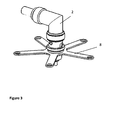
- FIG. 3 shows the grounding connector 8 in connection with the signal connector 2.
Landscapes
- Physics & Mathematics (AREA)
- General Physics & Mathematics (AREA)
- Details Of Connecting Devices For Male And Female Coupling (AREA)
- Measuring Instrument Details And Bridges, And Automatic Balancing Devices (AREA)
- Connections Arranged To Contact A Plurality Of Conductors (AREA)
Abstract
Description
- The invention relates to a measurement device in which voltage and/or a current sensor in a casted measurement device housing, wherein the sensor component is connected with a externally ending output connector by a signal wire, and with a grounding wire to a grounding output connector, where signal connector output and grounding connector output results as the electrical connecting terminal, according to the preamble of
claim 1. - The traditional approach of a measurement device connector holder relies on a special fixation component to ensure the connector placement in the defined position during manufacturing process. Such special fixation component is a part of the casting mould or it is removeable after manufacturing process. In both cases it has no job within the measurement device functionality after the manufacturing process.
From the measurement device grounding system point of view, the appropriate interconnection between active internal parts point(s) which must be grounded and the earth potential is performed by a separate conductor connected to a sensing component on the one side and, on the oposite side, for example to an additional metal insert which is afterwards grounded. - It is an object of the invention to ensure an accurate positioning of the voltage and/or current measurement device during the molding process, as well as a sure mechanical and electrical fixation of the connecting terminal at the ready measurement device.
- So this is solved by the features of the invention, which are,
that a further mechanical element (8) is arranged at the electrical connecting terminal, and provided with a central hole (10), through which the signal connector output is feeded, and at least one further connecting finger (8'), which is used as electrical
grounding connection as well as a mechanical fixation of the electrical connecting terminal during the moulding process. - So, during the molding process, the invention related mechanical element ensures an accurate positioning of the connecting signal terminal. Additionally to that this element has the implemented function of a grounding connector holder as well.
- So in order to combine measurement device connector fixation function during manufacturing process and a conductive connection function within the measurement device grounding system during the period when the measurement device is in use, it is proposed to integrate these requirements in a common solution.
This differs from the state of the art, in which mechanical fixation and electrical grounding connection will be handeld by separated elements. - In a further embodiment is proposed, that the mechanical element is provided with a central plate, where the central hole is arranged, and with at least one finger element aligned away from the central plate. So the signal output connector is positioned very accurate during the molding process.
- In a further advantageous embodiment at least three finger element are arranged circular and equidistant to each other around the central plate and the central hole.
- In a further advantageous embodiment each of the fingers are provided with holes near the end of each fingers.
- In a further advantageous embodiment is proposed, that the central hole has a section which differs from a circular cercumferential inner line, in that way, that the mechanical/connecting element is provided with that with an antitwist protection relative to connector.
- The invention is shown in the drawing and described as follows.
- In order to combine measurement device connector fixation function during manufacturing process and a conductive connection function within the measurement device grounding system during the period when the measurement device is in use, it is proposed to integrate these requirements separate solutions, into a single component solution.
Such component 8 will be fixed to the measurement device body 4 and/or to any internal current and/orvoltage sensing part 6 and/or to amould 3 in one or more points on the one side and to the measurement device input and/oroutput connector 2 in one or more points on the oposite side. Conductive coupling between theconnector holder 8 and the current and/orvoltage sensing part 6 will be solved either as the direct connection by aconductor 5, seeFig. 1 , or by a dedicated section of thegrounding connector holder 8 connected to the voltage and/orcurrent sensing element 6, or as an indirect connection whenconnector holder 8 will be conductively coupled with theconnector 2 which will be conductively coupled with thesensing part 6.
Material of thecomponent 8 must be selected in such a way to ensure the providing both mechanical stability of themeasurement device connector 2 placement during manufacturing process and during the measurement device 4 operational time - mechanical deformation of any section of theconnector holder 8 due to a mechanical load as a result of theholder 8 fixation and theconnector 2 weight must be less than 10mm in any axes direction - and electrical properties to ensure sufficient electrical charge transfer within its functionality as a part of the measurement device grounding system.
The advantage of the proposed solution is the combination of mechanical and electrical functionality within one single part, what means less complete assembly components, easirer manufacturing process, reduced manufacturing time and reduced production costs of the final measurement device.
Additional advantage of the proposed solution is the reinforcing effect of thegrounding holder 8 of theconnector 2 to the measurement device body 4 structure. -
Figure 2 shows thegrounding connector holder 8 in detail. This embodiment of thegroud connector holder 8 shows thecentral hole 10, through is feeded thesignal connectors 2 shown infigure 1 . Furthermore is shown infigure 2 , that this hole is not perfect round, but has a section which differs from a perfect round inner line, in order to correspond mechanically with a complementive outer surface of the connector in such a way, that with this is implemented an antitwist element.
Furthermore thegrounding connector holder 8 has five fingerelements 8' whoich are arrangned circular around the inner plate section of theholder 8. These fingers hasholes 8" at each their ends for mechanical and/or electrical connection to ground potential. -
Figure 3 shows thegrounding connector 8 in connection with thesignal connector 2. -
- 1
- Fixation component
- 2
- Signal input and/or output connector
- 3
- Mould
- 4
- Measurement device body
- 5
- Conductor
- 6
- Sensing part/sensor
- 8
- grounding connector holder
- 8'
- finger element
- 8"
- hole in finger element
- 10
- central hole
Claims (5)
- Measurement device in which voltage and/or a current sensor in a casted measurement device housing, wherein the sensor component is connected with a externally ending output connector by a signal wire, and with a grounding wire to a grounding output connector, where signal connector output and grounding connector output results as the electrical connecting terminal,
characterized in
that a further mechanical element (8) is arranged at the electrical connecting terminal, and provided with a central hole (10), through which the signal connector output is feeded, and at least one further connecting finger (8'), which is used as electrical grounding connection as well as a mechanical fixation of the electrical connecting terminal during the moulding process. - Measurement device according to claim 1,
characterized in
that the mechanical element (8) is provided with a central plate, where the central hole is arranged, and with at least one finger element (8') aligned away from the central plate. - Measurement device according to claim 1 or 2,
characterized in
that at least three finger element (8') are arranged circular and equidistant to each other around the central plate and the central hole (10). - Measurement device according to claim 1, or 2, or3,
characterized in
that each of the fingers (8') are provided with holes (8") near the end of each fingers (8'). - Measurement device according to one of the aforesaid claims,
characterized in
that the central hole has a section which differs from a circular cercumferential inner line, in that way, that the mechanical/connecting element (8) is provided with that with an antitwist protection relative to connector (2).
Priority Applications (5)
| Application Number | Priority Date | Filing Date | Title |
|---|---|---|---|
| EP12007205.3A EP2722932A1 (en) | 2012-10-18 | 2012-10-18 | Ground connection for a casted measurement device housing |
| EP13779142.2A EP2909892B1 (en) | 2012-10-18 | 2013-10-17 | Manufacturing process for a voltage and/or current sensor in a casted measurement device, and sensor itself |
| BR112015008397A BR112015008397A8 (en) | 2012-10-18 | 2013-10-17 | EARTH CONNECTION FOR HOUSING A CAST MEASUREMENT DEVICE |
| CN201380064183.7A CN104838542B (en) | 2012-10-18 | 2013-10-17 | Grounding connection for the measurement apparatus housing of casting |
| PCT/EP2013/003126 WO2014060105A1 (en) | 2012-10-18 | 2013-10-17 | Ground connection for a casted measurement device housing |
Applications Claiming Priority (1)
| Application Number | Priority Date | Filing Date | Title |
|---|---|---|---|
| EP12007205.3A EP2722932A1 (en) | 2012-10-18 | 2012-10-18 | Ground connection for a casted measurement device housing |
Publications (1)
| Publication Number | Publication Date |
|---|---|
| EP2722932A1 true EP2722932A1 (en) | 2014-04-23 |
Family
ID=47080164
Family Applications (2)
| Application Number | Title | Priority Date | Filing Date |
|---|---|---|---|
| EP12007205.3A Withdrawn EP2722932A1 (en) | 2012-10-18 | 2012-10-18 | Ground connection for a casted measurement device housing |
| EP13779142.2A Active EP2909892B1 (en) | 2012-10-18 | 2013-10-17 | Manufacturing process for a voltage and/or current sensor in a casted measurement device, and sensor itself |
Family Applications After (1)
| Application Number | Title | Priority Date | Filing Date |
|---|---|---|---|
| EP13779142.2A Active EP2909892B1 (en) | 2012-10-18 | 2013-10-17 | Manufacturing process for a voltage and/or current sensor in a casted measurement device, and sensor itself |
Country Status (4)
| Country | Link |
|---|---|
| EP (2) | EP2722932A1 (en) |
| CN (1) | CN104838542B (en) |
| BR (1) | BR112015008397A8 (en) |
| WO (1) | WO2014060105A1 (en) |
Citations (3)
| Publication number | Priority date | Publication date | Assignee | Title |
|---|---|---|---|---|
| US4210374A (en) * | 1978-03-03 | 1980-07-01 | Atlas Technologies Inc. | Set-screw bushing including integral electrical clamp |
| US6238222B1 (en) * | 1999-12-14 | 2001-05-29 | Hon Hai Precision Ind. Co., Ltd. | Grounding device for an electrical connector |
| US20060237210A1 (en) * | 2005-04-26 | 2006-10-26 | Thomas & Betts International, Inc. | Ground wire connector |
-
2012
- 2012-10-18 EP EP12007205.3A patent/EP2722932A1/en not_active Withdrawn
-
2013
- 2013-10-17 BR BR112015008397A patent/BR112015008397A8/en not_active Application Discontinuation
- 2013-10-17 EP EP13779142.2A patent/EP2909892B1/en active Active
- 2013-10-17 WO PCT/EP2013/003126 patent/WO2014060105A1/en not_active Ceased
- 2013-10-17 CN CN201380064183.7A patent/CN104838542B/en active Active
Patent Citations (3)
| Publication number | Priority date | Publication date | Assignee | Title |
|---|---|---|---|---|
| US4210374A (en) * | 1978-03-03 | 1980-07-01 | Atlas Technologies Inc. | Set-screw bushing including integral electrical clamp |
| US6238222B1 (en) * | 1999-12-14 | 2001-05-29 | Hon Hai Precision Ind. Co., Ltd. | Grounding device for an electrical connector |
| US20060237210A1 (en) * | 2005-04-26 | 2006-10-26 | Thomas & Betts International, Inc. | Ground wire connector |
Also Published As
| Publication number | Publication date |
|---|---|
| CN104838542B (en) | 2017-10-31 |
| EP2909892A1 (en) | 2015-08-26 |
| WO2014060105A1 (en) | 2014-04-24 |
| EP2909892B1 (en) | 2018-12-05 |
| BR112015008397A8 (en) | 2017-12-19 |
| CN104838542A (en) | 2015-08-12 |
| BR112015008397A2 (en) | 2017-07-04 |
Similar Documents
| Publication | Publication Date | Title |
|---|---|---|
| US10658774B2 (en) | Method of assembling a vehicular camera having coaxial connector | |
| EP2905842A1 (en) | Terminal and terminal manufacturing method | |
| EP2816361B1 (en) | Conductor assembly | |
| US9356362B2 (en) | Component unit | |
| EP3499246B1 (en) | Voltage divider assembly | |
| CN103968867A (en) | Adapter device with a mechanical interface for a measuring device | |
| EP2568584A3 (en) | Electric machine shaft grounding system | |
| CN107069350B (en) | Self-powered mating detection connector | |
| DE202018002389U1 (en) | Electronic system and device for determining the force / power that a cyclist exerts on a bicycle pedal | |
| DE102018109547B4 (en) | Charging connector | |
| EP2417670A1 (en) | Low profile compact rf coaxial to planar transmission line interface | |
| EP2958196A1 (en) | Cable with molded resin | |
| EP2722932A1 (en) | Ground connection for a casted measurement device housing | |
| EP2871447B1 (en) | Arrangement for monitoring a component rotating around its axis with a rotational speed sensor and a temperature sensor | |
| WO2019023094A1 (en) | Cable connector | |
| US20140318261A1 (en) | Intermediate connector | |
| EP1801918A3 (en) | Connector and electronic device equipped with the same | |
| US8766094B2 (en) | Grounding adapter for shielded cable | |
| CN208158718U (en) | A kind of high-definition camera improving ESD problem | |
| CN106329274B (en) | The processing method of the connection protective device of radio frequency co-axial cable subassembly | |
| JP2015191874A (en) | USB connector | |
| KR101457429B1 (en) | Multi Connecter for Vehicle | |
| EP2833155A1 (en) | Current and/or voltage sensing device with phase error compensation | |
| KR200484885Y1 (en) | Probe tip adapter for measuring connector pin | |
| CN109672047A (en) | Pin connector |
Legal Events
| Date | Code | Title | Description |
|---|---|---|---|
| PUAI | Public reference made under article 153(3) epc to a published international application that has entered the european phase |
Free format text: ORIGINAL CODE: 0009012 |
|
| AK | Designated contracting states |
Kind code of ref document: A1 Designated state(s): AL AT BE BG CH CY CZ DE DK EE ES FI FR GB GR HR HU IE IS IT LI LT LU LV MC MK MT NL NO PL PT RO RS SE SI SK SM TR |
|
| AX | Request for extension of the european patent |
Extension state: BA ME |
|
| 17P | Request for examination filed |
Effective date: 20141018 |
|
| RBV | Designated contracting states (corrected) |
Designated state(s): AL AT BE BG CH CY CZ DE DK EE ES FI FR GB GR HR HU IE IS IT LI LT LU LV MC MK MT NL NO PL PT RO RS SE SI SK SM TR |
|
| STAA | Information on the status of an ep patent application or granted ep patent |
Free format text: STATUS: THE APPLICATION IS DEEMED TO BE WITHDRAWN |
|
| 18D | Application deemed to be withdrawn |
Effective date: 20141024 |