EP2722679A1 - Fastening means for current and/or voltage sensor - Google Patents
Fastening means for current and/or voltage sensor Download PDFInfo
- Publication number
- EP2722679A1 EP2722679A1 EP12007204.6A EP12007204A EP2722679A1 EP 2722679 A1 EP2722679 A1 EP 2722679A1 EP 12007204 A EP12007204 A EP 12007204A EP 2722679 A1 EP2722679 A1 EP 2722679A1
- Authority
- EP
- European Patent Office
- Prior art keywords
- section
- fastening
- fastening means
- means according
- aforesaid
- Prior art date
- Legal status (The legal status is an assumption and is not a legal conclusion. Google has not performed a legal analysis and makes no representation as to the accuracy of the status listed.)
- Withdrawn
Links
- 239000004020 conductor Substances 0.000 claims abstract description 32
- 230000001850 reproductive effect Effects 0.000 abstract description 3
- 238000005259 measurement Methods 0.000 description 10
- 238000004519 manufacturing process Methods 0.000 description 6
- 239000000463 material Substances 0.000 description 5
- 238000010276 construction Methods 0.000 description 2
- 238000000034 method Methods 0.000 description 2
- 239000000853 adhesive Substances 0.000 description 1
- 230000001070 adhesive effect Effects 0.000 description 1
- 238000005520 cutting process Methods 0.000 description 1
- 230000003247 decreasing effect Effects 0.000 description 1
- 238000006073 displacement reaction Methods 0.000 description 1
- 230000000694 effects Effects 0.000 description 1
- 230000008030 elimination Effects 0.000 description 1
- 238000003379 elimination reaction Methods 0.000 description 1
- 238000012423 maintenance Methods 0.000 description 1
- 238000004904 shortening Methods 0.000 description 1
- 230000006641 stabilisation Effects 0.000 description 1
- 238000011105 stabilization Methods 0.000 description 1
Images

Classifications
-
- G—PHYSICS
- G01—MEASURING; TESTING
- G01R—MEASURING ELECTRIC VARIABLES; MEASURING MAGNETIC VARIABLES
- G01R15/00—Details of measuring arrangements of the types provided for in groups G01R17/00 - G01R29/00, G01R33/00 - G01R33/26 or G01R35/00
- G01R15/14—Adaptations providing voltage or current isolation, e.g. for high-voltage or high-current networks
- G01R15/18—Adaptations providing voltage or current isolation, e.g. for high-voltage or high-current networks using inductive devices, e.g. transformers
- G01R15/183—Adaptations providing voltage or current isolation, e.g. for high-voltage or high-current networks using inductive devices, e.g. transformers using transformers with a magnetic core
-
- H—ELECTRICITY
- H01—ELECTRIC ELEMENTS
- H01F—MAGNETS; INDUCTANCES; TRANSFORMERS; SELECTION OF MATERIALS FOR THEIR MAGNETIC PROPERTIES
- H01F27/00—Details of transformers or inductances, in general
- H01F27/06—Mounting, supporting or suspending transformers, reactors or choke coils not being of the signal type
Definitions
- the invention relates to fasting means for current and/or voltage sensor in low- medium and high voltage use according to the preamble of claim 1.
- a required position of a ring-core type low-, medium- or high- current and/or voltage sensing device is achieved by the sensing device design and its dimensions and by construction of an electrical device containing a source, i. e. a sensing device primary conductor, of a current and/or voltage signal to be measured.
- a source i. e. a sensing device primary conductor
- Next disadvantage of the solution described above, especially in using tightening straps is impossibility of the requested perpendicularity to the primary conductor and centering of the sensing device around the primary conductor ensurance what can lead to decreased measurement device sensing accuracy.
- the fastening device comprise a number of at least two fastening elements, each with a dowel pin clip, or a clamp at a first section of the fastening element, and a support element at a second section of the fastening element, so that the dowel pin clip or the clamp has to be inserted into, or clamped on the sensors housing at the first section, and the support element at the second section has to be fixed on the electrical conductor.
- the support element of an arrangement of the at least two fastening elements are fixed on the electrical conductor commonly with a tightening strap or a fixating ring. This ensures an accurate and stabilized position of a voltage and/or current measurement device within the measured voltage and/or current signal source which has possitive effect to the voltage and/or current measurement device sensing accuracy.
- a good centered position of the sensor is given. But better are at least three fastening element.
- the support element is provided with an eye-element, through which the tightening strap or fixation ring is guided, in order to fixe the position of the fastening element.
- the senor geometry is a circular ring element, to be positioned round an electrical conductor.
- fixating ring or the tightening strap is removable, and or changeable in the position.
- this inventive fastening element there is no need to use an assembling tool and/or additional fastening material, they provide an option to apply a tightening strap, conducted through a specially designed segment, like an eye, of the mechanical fastening element and/or placed on the mechanical fastening element surface to obtain greater contact force if needed.
- first section and the second section of the fastening element are connected together in a fixed angle position between 90° and 180°. Usually advantageous is an angle defined by 90°.
- first section and the second section of the fastening element are connected in that way, that the angle position between the first and the second section is variable/adjustable between 90° and 180°.
- This embodiment has its advantage in the in applications to electrical conductors with small diameters.
- the fastening element can be applied on several different conductor diameters.
- a last advantageous embodiment describes, that the first section is pivotable relative to the second section in that way, that the pivotation plane is rectangular to the long axis of the conductor. This gives a simple but effective possibility to adapt the fastening elements to lower conductor diameter.
- a last advantageous embodiment comprises the feature, that the contact side of the second section of the fastening element to the conductor surface is provided with a rough or structured surface or with such a surface coverage.
- the invention is dealing with an improvement of a current and/or voltage sensing means or device positioning system and with increasing measurement device sensing accuracy as a result of the stable and fixed measurement device placement within a complete electrical system. It claims implementation of the unique fastening elements designed to ensure fast and easy instalation and stabilization of the current and/or voltage sensing device in a proper position with no assembling tool usage and, thus, to reduce amplitude error and phase displacement, as well as to reduce manufacturing time and production costs.
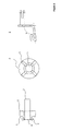
- this invention describes the application of the special construction fastening elements 3 ensuring the simple sensing device 2 fixation in the most appropriate position on the primary conductor 1 and, therefore a stable current and/or voltage signals measurement with high accuracy, like shown in figure 1 .
- the fastening element 3 design which allows a possibility of using a tightening strap 4 conducted through a hole or eye-element 5 and/or placed on the fastening element 3 surface, like shown in figure 1 and figure 2 .
- the first section 3' is provided with a dowel pin 10, which has to be inserted into a hole in the housing of the sensor 2.
- the first section 3' is oriented in an angle of 90° to the second section 3".
- the second section 3" has to be brought into close contact to the surface of the conductor 1.
- the contact side of the second section is provided with a structured surface area 11 or a such structured coverage.
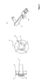
- Figure 2 shows the special design of the fastening element 3 that could be an option for the applications, where the primary conductor diameter is significantly smaller in comparison to the measurement of device 2 inners diameter.
- the proper contact force value between the fastening elements 3 and neither directly the primary conductor 1 or the electrical device containing the primary conductor 1 is ensured by introduction of the angle A, that has to be in the range 90° to 180°. This angle is defined between the first section and the second section of the fastening element.
- Figure 3 displays the concept of a pivotable first section 3' of the fastening element 3. So the first section 3' is pivotable to the second section, in a pivotation plane, which is rectangular to the long axis of conductor 2.
- Such a solution allows usage of the same sensing device 2, employing those rotating fastening elements 3, in the applications with different primary conductor 1 diameters and/or in the applications with different electrical device containing the primary conductor 3 sizes.
- Material of the fastening components must be selected in such way to ensure the requested mechanical stability of the current and/or voltage measurement device, sufficient contact force between the fastening component surface and a surface of a device to which the current and/or voltage sensing device containing the fastening components is to be connected and easy mounting process and removal process of the current and/or voltage measurement device.
- the next advantages are very easy and fast sensing device 2 mounting and removal and, as well, simple maintenance.
- the fastening of the sensor needs no special tools, and the positioning of the sensor could be realized with high reproductive accuracy.
Landscapes
- Engineering & Computer Science (AREA)
- Power Engineering (AREA)
- Physics & Mathematics (AREA)
- General Physics & Mathematics (AREA)
- Measuring Instrument Details And Bridges, And Automatic Balancing Devices (AREA)
- Clamps And Clips (AREA)
- Measuring Fluid Pressure (AREA)
Abstract
Description
- The invention relates to fasting means for current and/or voltage sensor in low- medium and high voltage use according to the preamble of
claim 1. - A required position of a ring-core type low-, medium- or high- current and/or voltage sensing device is achieved by the sensing device design and its dimensions and by construction of an electrical device containing a source, i. e. a sensing device primary conductor, of a current and/or voltage signal to be measured. For fastening of the sensing device to the electrical device containing the primary conductor there is used either tightening strap or another supplementary fastening material such the bolts, an adhesive, etc. It introduces necessity of the additional fastening material and special assembling tools application what negatively influences the manufacturing time and production costs. Next disadvantage of the solution described above, especially in using tightening straps, is impossibility of the requested perpendicularity to the primary conductor and centering of the sensing device around the primary conductor ensurance what can lead to decreased measurement device sensing accuracy.
- So it is an object of the invention to enhance fasting means or device for fasting current and/or voltage sensors in such a way, that the fixation is accurate and reproductive as well.
- So based on this, the invention is, that the fastening device comprise a number of at least two fastening elements, each with a dowel pin clip, or a clamp at a first section of the fastening element, and a support element at a second section of the fastening element, so that the dowel pin clip or the clamp has to be inserted into, or clamped on the sensors housing at the first section, and the support element at the second section has to be fixed on the electrical conductor.
- In an advantageous embodiment the support element of an arrangement of the at least two fastening elements are fixed on the electrical conductor commonly with a tightening strap or a fixating ring. This ensures an accurate and stabilized position of a voltage and/or current measurement device within the measured voltage and/or current signal source which has possitive effect to the voltage and/or current measurement device sensing accuracy. By the use of two fastening elements a good centered position of the sensor is given. But better are at least three fastening element.
- In a further embodiment, the support element is provided with an eye-element, through which the tightening strap or fixation ring is guided, in order to fixe the position of the fastening element.
- So in a very advantageous embodiment, the sensor geometry is a circular ring element, to be positioned round an electrical conductor.
- In a further advantageous embodiment, the fixating ring or the tightening strap is removable, and or changeable in the position.
- For fixation of this inventive fastening element there is no need to use an assembling tool and/or additional fastening material, they provide an option to apply a tightening strap, conducted through a specially designed segment, like an eye, of the mechanical fastening element and/or placed on the mechanical fastening element surface to obtain greater contact force if needed.
- In a further embodiment the first section and the second section of the fastening element are connected together in a fixed angle position between 90° and 180°. Mostly advantageous is an angle defined by 90°.
- An alternative embodiment is given by that the first section and the second section of the fastening element are connected in that way, that the angle position between the first and the second section is variable/adjustable between 90° and 180°.
- This embodiment has its advantage in the in applications to electrical conductors with small diameters. As well, by this embodiment, the fastening element can be applied on several different conductor diameters.
- A last advantageous embodiment describes, that the first section is pivotable relative to the second section in that way, that the pivotation plane is rectangular to the long axis of the conductor. This gives a simple but effective possibility to adapt the fastening elements to lower conductor diameter.
- A last advantageous embodiment comprises the feature, that the contact side of the second section of the fastening element to the conductor surface is provided with a rough or structured surface or with such a surface coverage.
- By this, a very good contact an sure positioning is given.
- The invention is dealing with an improvement of a current and/or voltage sensing means or device positioning system and with increasing measurement device sensing accuracy as a result of the stable and fixed measurement device placement within a complete electrical system. It claims implementation of the unique fastening elements designed to ensure fast and easy instalation and stabilization of the current and/or voltage sensing device in a proper position with no assembling tool usage and, thus, to reduce amplitude error and phase displacement, as well as to reduce manufacturing time and production costs.
- The inventions is shown in
-
Figure 1 : side, front and detailed view of the fastening element with rectangular position of first to second section, -
Figure 2 : side, front and detailed view of the fastening element with angular position between 90 and 180°of first to second section, -
Figure 3 : side, front and detailed view of the fastening element with a pivotable first section - According to all embodiments this invention describes the application of the special
construction fastening elements 3 ensuring thesimple sensing device 2 fixation in the most appropriate position on theprimary conductor 1 and, therefore a stable current and/or voltage signals measurement with high accuracy, like shown infigure 1 . In case the greater contact force value between thefastening elements 3 and neither directly theprimary conductor 1 or the electrical device containing theprimary conductor 1 is needed thefastening element 3 design, which allows a possibility of using a tightening strap 4 conducted through a hole or eye-element 5 and/or placed on thefastening element 3 surface, like shown infigure 1 andfigure 2 . - In
figure 1 , the first section 3' is provided with adowel pin 10, which has to be inserted into a hole in the housing of thesensor 2. The first section 3' is oriented in an angle of 90° to thesecond section 3". Thesecond section 3" has to be brought into close contact to the surface of theconductor 1. For a good positioning, the contact side of the second section is provided with astructured surface area 11 or a such structured coverage. -
Figure 2 shows the special design of thefastening element 3 that could be an option for the applications, where the primary conductor diameter is significantly smaller in comparison to the measurement ofdevice 2 inners diameter. The proper contact force value between thefastening elements 3 and neither directly theprimary conductor 1 or the electrical device containing theprimary conductor 1 is ensured by introduction of the angle A, that has to be in the range 90° to 180°. This angle is defined between the first section and the second section of the fastening element. -
Figure 3 displays the concept of a pivotable first section 3' of thefastening element 3. So the first section 3' is pivotable to the second section, in a pivotation plane, which is rectangular to the long axis ofconductor 2. Such a solution allows usage of thesame sensing device 2, employing those rotatingfastening elements 3, in the applications with differentprimary conductor 1 diameters and/or in the applications with different electrical device containing theprimary conductor 3 sizes. - Material of the fastening components must be selected in such way to ensure the requested mechanical stability of the current and/or voltage measurement device, sufficient contact force between the fastening component surface and a surface of a device to which the current and/or voltage sensing device containing the fastening components is to be connected and easy mounting process and removal process of the current and/or voltage measurement device.
- The advantages of the proposed solution are the reduction of the fastening material needed and the elimination of the special assembling tool necessity which enables both shortening of the manufacturing time and production cost cutting.
- The next advantages are very easy and
fast sensing device 2 mounting and removal and, as well, simple maintenance. - Additional significant advantage of the
special fastening elements 3 application, as described above, is improved sensing accuracy of themeasurement device 2 ensured by the stable and fixedsensing device 2 position within the measured current and/or voltage signal source (i.e. primary conductor 1). - The fastening of the sensor needs no special tools, and the positioning of the sensor could be realized with high reproductive accuracy.
-
- 1
- electrical conductor
- 2
- sensor / sensor housing
- 3
- fastening element
- 3'
- first section of the fastening element
- 3"
- second section of the fastening element
- 4
- tightening strip
- 5
- eye-element
- 10
- dowel pin or clamp
- 11
- strutured surface area, or structured coverage
Claims (9)
- Fastening means or device for fastening a voltage and/or current sensor on a electrical conductor,
characterized in
that the fastening device comprise of a number of at least two fastening elements (3), each with a dowel pin clip, or a clamp at a first section (3') of the fastening element, and a support element at a second section (3") of the fastening element, so that the dowel pin clip (10) or the clamp has to be inserted into, or clamped on the housing of the sensor (2) at the first section (3'), and the support element at the second section (3") has to be fixed on the electrical conductor (1). - Fastening means according to claim 1,
characterized in
that the support element of an arrangement of the at least two fastening elements are fixed on the electrical conductor commonly with a tightening strap (4) or a fixating ring. - Fastening means according to claim 1 or 2,
characterized in
that the support element is provided with an eye-element (5), through which the tightening strap (4) or fixation ring is guided, in order to fixe the position of the fastening element. - Fastening means according to claim 1 or 2, or 3,
characterized in
that the sensor geometrie is a circular ring element, to be positioned round an electrical conductor. - Fastening means according to one of the aforesaid claims,
characterized in
that the fixating ring or the tightening strap is removable, and or changeable in the position. - Fastening means according to one of the aforesaid claims 1 to 5,
characterized in
that the first section and the second section of the fastening element are connected together in a fixed angle position between 90° and 180°. - Fastening means according to one of the aforesaid claims 1 to 5,
characterized in
that the first section (3') and the second section (3") of the fastening element are connected in that way, that the angle position between the first and the second section is variable between 90° and 180°. - Fastening means according to one of the aforesaid claims 1 to 5,
characterized in
that the first section (3') is pivotable relative to the second section (3") in that way, that the pivotation plane is rectangular to the long axis of the conductor. - Fastening means according to one of the aforesaid claims,
characterized in
that the contact side of the second section (3") of the fastening element to the conductor surface is provided with a rough or structured surface (11) or with such a surface coverage.
Priority Applications (7)
| Application Number | Priority Date | Filing Date | Title |
|---|---|---|---|
| EP12007204.6A EP2722679A1 (en) | 2012-10-18 | 2012-10-18 | Fastening means for current and/or voltage sensor |
| EP13779735.3A EP2909642B1 (en) | 2012-10-18 | 2013-10-17 | Fastening means for current and/or voltage sensor |
| PCT/EP2013/003125 WO2014060104A1 (en) | 2012-10-18 | 2013-10-17 | Fastening means for current and/or voltage sensor |
| HUE13779735A HUE031781T2 (en) | 2012-10-18 | 2013-10-17 | Fastening means for current and/or voltage sensor |
| BR112015008435A BR112015008435A8 (en) | 2012-10-18 | 2013-10-17 | FIXING MEANS FOR CURRENT AND/OR VOLTAGE SENSORS |
| CN201380060014.6A CN104797945B (en) | 2012-10-18 | 2013-10-17 | Fastening device for current sensor and/or voltage sensor |
| DK13779735.3T DK2909642T3 (en) | 2012-10-18 | 2013-10-17 | MOUNTING CIRCUIT FOR THE CURRENT AND / OR VOLTAGE SENSOR |
Applications Claiming Priority (1)
| Application Number | Priority Date | Filing Date | Title |
|---|---|---|---|
| EP12007204.6A EP2722679A1 (en) | 2012-10-18 | 2012-10-18 | Fastening means for current and/or voltage sensor |
Publications (1)
| Publication Number | Publication Date |
|---|---|
| EP2722679A1 true EP2722679A1 (en) | 2014-04-23 |
Family
ID=47146138
Family Applications (2)
| Application Number | Title | Priority Date | Filing Date |
|---|---|---|---|
| EP12007204.6A Withdrawn EP2722679A1 (en) | 2012-10-18 | 2012-10-18 | Fastening means for current and/or voltage sensor |
| EP13779735.3A Active EP2909642B1 (en) | 2012-10-18 | 2013-10-17 | Fastening means for current and/or voltage sensor |
Family Applications After (1)
| Application Number | Title | Priority Date | Filing Date |
|---|---|---|---|
| EP13779735.3A Active EP2909642B1 (en) | 2012-10-18 | 2013-10-17 | Fastening means for current and/or voltage sensor |
Country Status (6)
| Country | Link |
|---|---|
| EP (2) | EP2722679A1 (en) |
| CN (1) | CN104797945B (en) |
| BR (1) | BR112015008435A8 (en) |
| DK (1) | DK2909642T3 (en) |
| HU (1) | HUE031781T2 (en) |
| WO (1) | WO2014060104A1 (en) |
Cited By (3)
| Publication number | Priority date | Publication date | Assignee | Title |
|---|---|---|---|---|
| EP2982993A1 (en) * | 2014-08-08 | 2016-02-10 | General Electric Company | Sensor devices and methods for use in sensing current through a conductor |
| FR3038122A1 (en) * | 2015-06-29 | 2016-12-30 | Schneider Electric Ind Sas | DEVICE FOR SURROUNDING AN ELECTRICAL CONDUCTOR FOR GENERATING ELECTRICITY |
| GB2620759A (en) * | 2022-07-20 | 2024-01-24 | Gmc I Prosys Ltd | Current sensor |
Families Citing this family (1)
| Publication number | Priority date | Publication date | Assignee | Title |
|---|---|---|---|---|
| CN109470907B (en) * | 2018-12-06 | 2020-12-22 | 江苏海事职业技术学院 | A sensor based on new energy vehicle inverter current detection |
Citations (8)
| Publication number | Priority date | Publication date | Assignee | Title |
|---|---|---|---|---|
| JP2003072484A (en) * | 2001-09-05 | 2003-03-12 | Yazaki Corp | Mounting device for current sensor |
| US20080079437A1 (en) * | 2006-09-28 | 2008-04-03 | General Electric Company | Current Sensing Module and Assembly Method Thereof |
| CN101286412A (en) * | 2007-02-02 | 2008-10-15 | 湖北盛佳电器设备有限公司 | A piercing type current transformer for taking voltage from the sheathed wire |
| US20080284410A1 (en) * | 2007-05-16 | 2008-11-20 | Square D Company | Clamp-on current and voltage module for a power monitoring system |
| US20100155136A1 (en) * | 2008-12-18 | 2010-06-24 | Square D Company | Circuit Breaker Current Transformer Conductor Location Device For Improved Sensing Accuracy And Assembly |
| WO2011073397A1 (en) * | 2009-12-17 | 2011-06-23 | Phoenix Contact Gmbh & Co. Kg | Device for removably fixing a conductor to a current transformer housing |
| WO2011073434A1 (en) * | 2009-12-17 | 2011-06-23 | Phoenix Contact Gmbh & Co. Kg | Device for removably fixing a conductor to a current transformer housing |
| WO2011083030A1 (en) * | 2009-12-17 | 2011-07-14 | Phoenix Contact Gmbh & Co. Kg | Device for detachably fastening a current conductor to a current transformer housing |
-
2012
- 2012-10-18 EP EP12007204.6A patent/EP2722679A1/en not_active Withdrawn
-
2013
- 2013-10-17 EP EP13779735.3A patent/EP2909642B1/en active Active
- 2013-10-17 DK DK13779735.3T patent/DK2909642T3/en active
- 2013-10-17 BR BR112015008435A patent/BR112015008435A8/en not_active Application Discontinuation
- 2013-10-17 CN CN201380060014.6A patent/CN104797945B/en active Active
- 2013-10-17 HU HUE13779735A patent/HUE031781T2/en unknown
- 2013-10-17 WO PCT/EP2013/003125 patent/WO2014060104A1/en not_active Ceased
Patent Citations (8)
| Publication number | Priority date | Publication date | Assignee | Title |
|---|---|---|---|---|
| JP2003072484A (en) * | 2001-09-05 | 2003-03-12 | Yazaki Corp | Mounting device for current sensor |
| US20080079437A1 (en) * | 2006-09-28 | 2008-04-03 | General Electric Company | Current Sensing Module and Assembly Method Thereof |
| CN101286412A (en) * | 2007-02-02 | 2008-10-15 | 湖北盛佳电器设备有限公司 | A piercing type current transformer for taking voltage from the sheathed wire |
| US20080284410A1 (en) * | 2007-05-16 | 2008-11-20 | Square D Company | Clamp-on current and voltage module for a power monitoring system |
| US20100155136A1 (en) * | 2008-12-18 | 2010-06-24 | Square D Company | Circuit Breaker Current Transformer Conductor Location Device For Improved Sensing Accuracy And Assembly |
| WO2011073397A1 (en) * | 2009-12-17 | 2011-06-23 | Phoenix Contact Gmbh & Co. Kg | Device for removably fixing a conductor to a current transformer housing |
| WO2011073434A1 (en) * | 2009-12-17 | 2011-06-23 | Phoenix Contact Gmbh & Co. Kg | Device for removably fixing a conductor to a current transformer housing |
| WO2011083030A1 (en) * | 2009-12-17 | 2011-07-14 | Phoenix Contact Gmbh & Co. Kg | Device for detachably fastening a current conductor to a current transformer housing |
Cited By (5)
| Publication number | Priority date | Publication date | Assignee | Title |
|---|---|---|---|---|
| EP2982993A1 (en) * | 2014-08-08 | 2016-02-10 | General Electric Company | Sensor devices and methods for use in sensing current through a conductor |
| US9671434B2 (en) | 2014-08-08 | 2017-06-06 | Aclara Meters Llc | Sensor devices and methods for use in sensing current through a conductor |
| FR3038122A1 (en) * | 2015-06-29 | 2016-12-30 | Schneider Electric Ind Sas | DEVICE FOR SURROUNDING AN ELECTRICAL CONDUCTOR FOR GENERATING ELECTRICITY |
| GB2620759A (en) * | 2022-07-20 | 2024-01-24 | Gmc I Prosys Ltd | Current sensor |
| WO2024018214A1 (en) * | 2022-07-20 | 2024-01-25 | Gmc-I Prosys Ltd. | Current sensor |
Also Published As
| Publication number | Publication date |
|---|---|
| EP2909642A1 (en) | 2015-08-26 |
| CN104797945B (en) | 2018-07-03 |
| EP2909642B1 (en) | 2016-11-30 |
| WO2014060104A1 (en) | 2014-04-24 |
| BR112015008435A2 (en) | 2017-07-04 |
| CN104797945A (en) | 2015-07-22 |
| BR112015008435A8 (en) | 2017-12-19 |
| DK2909642T3 (en) | 2017-03-06 |
| HUE031781T2 (en) | 2017-07-28 |
Similar Documents
| Publication | Publication Date | Title |
|---|---|---|
| EP2722679A1 (en) | Fastening means for current and/or voltage sensor | |
| EP3002594A1 (en) | Voltage sensing device | |
| US9127974B2 (en) | Magnetic flowmeter assembly framework | |
| US10048143B2 (en) | Sensor unit and magnetism collecting module and sensor apparatus | |
| CN105388346A (en) | Holding device for a rogowski coil | |
| US11221345B2 (en) | Arrangement of a rotary pulse encoder and a clamping sleeve for sensing the speed of rotation of a rotor | |
| EP3244216B1 (en) | Current detector | |
| US20150008897A1 (en) | Scanning unit for scanning a scale and position-measuring device | |
| KR101072838B1 (en) | Electronic Wattmeter | |
| US20140340076A1 (en) | Sensor unit | |
| US9689904B2 (en) | Current sensor with stray magnetic field rejection | |
| JP2005134233A (en) | Measuring instrument | |
| JP2015172531A (en) | Shield member and current detection device using the same | |
| CN202708519U (en) | Magnetic gauge stand fixing bracket | |
| US20210131837A1 (en) | Self-supported portable sensor for liquids | |
| US20170038412A1 (en) | Probe cover | |
| JP2019168341A (en) | Film thickness meter alignment jig | |
| JP2013003127A (en) | Electric wire fixing structure of electric measuring instrument | |
| CN108983089A (en) | A kind of circuit breaker testing equipment | |
| CN105318799A (en) | Device for detecting arc-shaped element | |
| JP5441489B2 (en) | Load cell | |
| CN204269051U (en) | Angularity correction frock | |
| CN218896142U (en) | PT type probe | |
| CN103852179A (en) | Wireless temperature measuring sensor | |
| CN219201709U (en) | Rogowski coil type probe |
Legal Events
| Date | Code | Title | Description |
|---|---|---|---|
| PUAI | Public reference made under article 153(3) epc to a published international application that has entered the european phase |
Free format text: ORIGINAL CODE: 0009012 |
|
| AK | Designated contracting states |
Kind code of ref document: A1 Designated state(s): AL AT BE BG CH CY CZ DE DK EE ES FI FR GB GR HR HU IE IS IT LI LT LU LV MC MK MT NL NO PL PT RO RS SE SI SK SM TR |
|
| AX | Request for extension of the european patent |
Extension state: BA ME |
|
| 17P | Request for examination filed |
Effective date: 20141018 |
|
| RBV | Designated contracting states (corrected) |
Designated state(s): AL AT BE BG CH CY CZ DE DK EE ES FI FR GB GR HR HU IE IS IT LI LT LU LV MC MK MT NL NO PL PT RO RS SE SI SK SM TR |
|
| STAA | Information on the status of an ep patent application or granted ep patent |
Free format text: STATUS: THE APPLICATION IS DEEMED TO BE WITHDRAWN |
|
| 18D | Application deemed to be withdrawn |
Effective date: 20141024 |