EP2722493A2 - Fault detection system and method for overspeed protection speed sensors - Google Patents
Fault detection system and method for overspeed protection speed sensors Download PDFInfo
- Publication number
- EP2722493A2 EP2722493A2 EP13187496.8A EP13187496A EP2722493A2 EP 2722493 A2 EP2722493 A2 EP 2722493A2 EP 13187496 A EP13187496 A EP 13187496A EP 2722493 A2 EP2722493 A2 EP 2722493A2
- Authority
- EP
- European Patent Office
- Prior art keywords
- pulse train
- speed
- speed sensor
- rotating machine
- pulse
- Prior art date
- Legal status (The legal status is an assumption and is not a legal conclusion. Google has not performed a legal analysis and makes no representation as to the accuracy of the status listed.)
- Withdrawn
Links
- 238000001514 detection method Methods 0.000 title claims abstract description 27
- 238000000034 method Methods 0.000 title claims description 32
- 238000010586 diagram Methods 0.000 description 6
- 230000001010 compromised effect Effects 0.000 description 2
- 238000002405 diagnostic procedure Methods 0.000 description 2
- 230000035945 sensitivity Effects 0.000 description 2
- 230000001052 transient effect Effects 0.000 description 2
- 238000009825 accumulation Methods 0.000 description 1
- 230000004075 alteration Effects 0.000 description 1
- 230000000694 effects Effects 0.000 description 1
- 230000001747 exhibiting effect Effects 0.000 description 1
- 230000003287 optical effect Effects 0.000 description 1
- 238000007493 shaping process Methods 0.000 description 1
- 238000006467 substitution reaction Methods 0.000 description 1
Images

Classifications
-
- G—PHYSICS
- G05—CONTROLLING; REGULATING
- G05B—CONTROL OR REGULATING SYSTEMS IN GENERAL; FUNCTIONAL ELEMENTS OF SUCH SYSTEMS; MONITORING OR TESTING ARRANGEMENTS FOR SUCH SYSTEMS OR ELEMENTS
- G05B5/00—Anti-hunting arrangements
- G05B5/01—Anti-hunting arrangements electric
-
- F—MECHANICAL ENGINEERING; LIGHTING; HEATING; WEAPONS; BLASTING
- F01—MACHINES OR ENGINES IN GENERAL; ENGINE PLANTS IN GENERAL; STEAM ENGINES
- F01D—NON-POSITIVE DISPLACEMENT MACHINES OR ENGINES, e.g. STEAM TURBINES
- F01D21/00—Shutting-down of machines or engines, e.g. in emergency; Regulating, controlling, or safety means not otherwise provided for
- F01D21/02—Shutting-down responsive to overspeed
-
- H—ELECTRICITY
- H02—GENERATION; CONVERSION OR DISTRIBUTION OF ELECTRIC POWER
- H02P—CONTROL OR REGULATION OF ELECTRIC MOTORS, ELECTRIC GENERATORS OR DYNAMO-ELECTRIC CONVERTERS; CONTROLLING TRANSFORMERS, REACTORS OR CHOKE COILS
- H02P6/00—Arrangements for controlling synchronous motors or other dynamo-electric motors using electronic commutation dependent on the rotor position; Electronic commutators therefor
- H02P6/14—Electronic commutators
- H02P6/16—Circuit arrangements for detecting position
- H02P6/17—Circuit arrangements for detecting position and for generating speed information
-
- F—MECHANICAL ENGINEERING; LIGHTING; HEATING; WEAPONS; BLASTING
- F05—INDEXING SCHEMES RELATING TO ENGINES OR PUMPS IN VARIOUS SUBCLASSES OF CLASSES F01-F04
- F05D—INDEXING SCHEME FOR ASPECTS RELATING TO NON-POSITIVE-DISPLACEMENT MACHINES OR ENGINES, GAS-TURBINES OR JET-PROPULSION PLANTS
- F05D2260/00—Function
- F05D2260/80—Diagnostics
-
- F—MECHANICAL ENGINEERING; LIGHTING; HEATING; WEAPONS; BLASTING
- F05—INDEXING SCHEMES RELATING TO ENGINES OR PUMPS IN VARIOUS SUBCLASSES OF CLASSES F01-F04
- F05D—INDEXING SCHEME FOR ASPECTS RELATING TO NON-POSITIVE-DISPLACEMENT MACHINES OR ENGINES, GAS-TURBINES OR JET-PROPULSION PLANTS
- F05D2270/00—Control
- F05D2270/01—Purpose of the control system
- F05D2270/02—Purpose of the control system to control rotational speed (n)
- F05D2270/021—Purpose of the control system to control rotational speed (n) to prevent overspeed
-
- F—MECHANICAL ENGINEERING; LIGHTING; HEATING; WEAPONS; BLASTING
- F05—INDEXING SCHEMES RELATING TO ENGINES OR PUMPS IN VARIOUS SUBCLASSES OF CLASSES F01-F04
- F05D—INDEXING SCHEME FOR ASPECTS RELATING TO NON-POSITIVE-DISPLACEMENT MACHINES OR ENGINES, GAS-TURBINES OR JET-PROPULSION PLANTS
- F05D2270/00—Control
- F05D2270/30—Control parameters, e.g. input parameters
- F05D2270/304—Spool rotational speed
-
- H—ELECTRICITY
- H02—GENERATION; CONVERSION OR DISTRIBUTION OF ELECTRIC POWER
- H02P—CONTROL OR REGULATION OF ELECTRIC MOTORS, ELECTRIC GENERATORS OR DYNAMO-ELECTRIC CONVERTERS; CONTROLLING TRANSFORMERS, REACTORS OR CHOKE COILS
- H02P9/00—Arrangements for controlling electric generators for the purpose of obtaining a desired output
- H02P9/006—Means for protecting the generator by using control
Definitions
- the subject matter disclosed herein relates to control of a rotating machine and, more particularly, to over speed protection.
- an over-speed condition represents one of the primary hazard modes and can result in catastrophic failure with moving parts being liberated from the shaft.
- rotating machines typically include over-speed protection systems that mitigate damage from over-speed conditions by imposing a shutdown (tripping the system).
- over-speed protection system itself, and specifically the speed sensors used to implement the over-speed protection, is critical to reducing false alarms that impact efficiency and improving protection of the rotating machine in case of a real over-speed condition.
- a more reliable fault detection system and method for over-speed protection speed sensors would be appreciated in the power industry.
- a programmable logic device programmed to perform fault detection of an over-speed protection system for a rotating machine including a first speed sensor, second speed sensor, and third speed sensor sensing a speed of a shaft of the rotating machine includes a first input configured to receive a first pulse train from the first speed sensor; a second input configured to receive a second pulse train from the second speed sensor; a third input configured to receive a third pulse train from the third speed sensor; and a processor configured to generate a shutdown signal for the rotating machine based on the first pulse train, the second pulse train, and the third pulse train.
- a method, implemented by a processor, of detecting faults in an over-speed protection system of a rotating machine includes determining whether a first pulse train is received from a first speed sensor sensing a first speed of a shaft of the rotating machine; determining whether a second pulse train is received from a second speed sensor sensing a second speed of the shaft; determining whether a third pulse train is received from a third speed sensor sensing a third speed of the shaft; and when a specified number of the first pulse train, the second pulse train, and the third pulse train are determined to not be received, outputting a shutdown signal based on processing the first pulse train, the second pulse train, and the third pulse train.
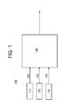
- FIG. 1 is a block diagram of a fault detection system 100 for over-speed protection system speed sensors 110, 120, 130 according to an embodiment of the invention.
- the system 100 includes three speed sensors 110, 120, 130 positioned on a shaft (not shown) of a rotating machine such as a turbomachine.
- each speed sensor 110, 120, 130 outputs a pulse 115, 125, 135 each time a toothed wheel associated with the shaft passes under the corresponding speed sensor 110, 120, 130.
- the number of pulses 115, 125, 135 output by each speed sensor 110, 120, 130 over a given duration corresponds with the speed of the shaft.
- other methods that translate rotational velocity to pulse rate may be used and may employ any device that creates an electrical signal with a frequency proportional to a rate of rotation.
- These other methods may include optical speed encoders and resolvers connected to pulse generation circuits.
- the methods may also employ a passive magnetic speed sensor that creates a sine wave output transformed into pulses by a wave shaping network.
- the pulses (pulse train) 115, 125, 135 output from the three speed sensors 110, 120, 130 are input to a processor 140.
- the processor 140 is a Field Programmable Gate Array (FPGA).
- programmable logic devices e.g., Complex Programmable Logic Device (CPLD), Application Specific Integrated Circuit ASIC
- processor configurations e.g., microprocessor devices
- the programmable logic devices or other implementations of the processor 140 have the technical effect of performing fault detection for the over-speed protection system speed sensors 110, 120, 130.
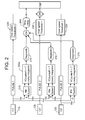
- FIG. 2 is a logic diagram of aspects of a processor 140 of FIG. 1 according to an embodiment of the invention.
- the exemplary FPGA processor 140 includes inputs 117, 127, 137 that receive pulses 115, 125, 135, respectively, from each of the three speed sensors 110, 120, 130.
- the pulses 115, 125, 135 from each of the speed sensors 110, 120, 130 is used to determine if the detected speed of the shaft exceeds a specified (over-speed) threshold at the block 230.
- the outputs of all of the speed sensors 110, 120, 130 should be the same such that the outputs of all three speed sensors 110, 120, 130 should indicate a speed exceeding the over-speed threshold at blocks 230 at the same time.
- the over-speed protection is compromised.
- the logic used by the processor 140 to perform fault detection of the speed sensors 110, 120, 130 and to maintain the integrity of the over-speed protection is detailed below.
- Each of the speed sensors 110, 120, 130 is paired with each of the other two speed sensors 110, 120, 130.
- the pulses 115, 125 of speed sensors 110, 120 are paired at A
- the pulses 125, 135 of speed sensors 120, 130 are paired at B
- the pulses 115, 135 of speed sensors 110, 130 are paired at C.
- a counter which acts as an error integrator 220 increments by one for each pulse 115, 125, 135 from one of the pair A, B, C and decrements by one for each pulse 115, 125, 135 from the other of the pair A, B, C.
- the error integrator 220a will increment the count for each pulse 115 from speed sensor 110 and decrement the count for each pulse 125 from speed sensor 120, while the error integrator 220b will increment the count for each pulse 125 from the speed sensor 120 and decrement the count for each pulse 135 from the speed sensor 130, and the error integrator 220c will increment the count for each pulse 115 from the speed sensor 110 and decrement the count for each pulse 135 from the speed sensor 130.
- every speed sensor 110, 120, 130 should generate a pulse 115, 125, 135 at the same time.
- each error integrator 220 should maintain a count of zero because, as one of the two speed sensors 110, 120, 130 associated with each error integrator 220 causes an increment in the count, the other of the two speed sensors 110, 120, 130 associated with each error integrator 220 causes a decrement of the count.
- each error integrator 220 decrements, by one count at a time towards zero, over a period of time.
- each error integrator 220 acts as a leaky integrator.
- a minimum speed detector 210 is used to ensure that a minimum speed is achieved before the processor 140 begins the fault detection process.
- the minimum speed is a threshold value that is set and adjusted, as needed, based on various factors including sensor capabilities.
- the minimum speed threshold may be set based on modeled or experimental results.
- the minimum speed threshold may be zero in some cases to ensure continuous operation of the fault detection. In other embodiments, the minimum speed may be set to a specific value (e.g., half the over-speed threshold value set at block 230).
- Detection of a faulty speed sensor 110, 120, 130 is indicated by a significant pulse count difference in an error integrator 220.
- any error integrator 220 detects a faulty speed sensor 110, 120, 130 (i.e., a significant difference in pulses being counted for the pair of speed sensors 110, 120, 130 input to it), that error integrator 220 votes for a shutdown of the rotating machine.
- over-speed protection integrity is enhanced in the following way.
- two of the error integrators 220 will detect a fault and vote for a shutdown based on a mismatch of pulse counts.
- the error integrator 220a comparing pulses 115, 125 from speed sensors 110, 120
- 220b comparing pulses 125, 135 from speed sensors 120, 130
- the fault detection system 100 does not shut down the rotating machine because two of the speed sensors (110, 130 in the exemplary case) are functioning properly and have pulses 115, 135 that agree in pulse count at error integrator 220c.
- all three error integrators 220 detect pulse count differences.
- the error integrator 220a comparing pulses 115, 125 from speed sensors 110, 120
- the error integrator 220b comparing pulses 125, 135 from speed sensors 120, 130
- the error integrator 220c comparing pulses 115, 135 from speed sensors 110, 130
- the fault detection system 100 does shut down the rotating machine because, with at least two of the three speed sensors 110, 120, 130 exhibiting faults, the integrity of the over-speed protection system is compromised.
- a time delay (block 260) is first implemented prior to shutdown of the rotating machine. This time delay ( FIG. 2 , block 260) allows an operator to do a machine shutdown prior to an automated trip. Additionally, each instance of a fault detection (significant pulse count difference) at a given error integrator 220 is followed by a diagnostic process (at block 270) before the shutdown vote by the error integrator 220 is processed.
- the diagnostic process (block 270) includes a repair that may eliminate the fault.
- the blocks 240 and 250 may represent one-out-of-three and two-out-of-three conditions, respectively.
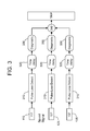
- FIG. 3 is a logic diagram of other aspects of the processor 140 of FIG. 1 according to an embodiment of the invention.
- the detection of pulse count differences was discussed with reference to FIG. 2 .
- Another possible issue for a given speed sensor 110, 120, 130, in addition to a mis-count, is a loss of pulse count.
- the loss of pulse inputs to an error integrator 220 appears as a sudden decrease in pulse inputs over the short term.
- the rapid decrease in pulse inputs, faster than expected for a decelerating shaft indicates a loss of signal from a speed sensor 110, 120, 130 or a failure of a speed sensor 110, 120, 130 at block 310.
- a time delay ensures that the loss of pulses is a permanent condition due to a failure of a speed sensor 110, 120, 130 rather than a transient condition. If the loss of pulses results from transient dropped pulses (i.e., pulses 115, 125, 135 are all detected after the time delay at 320), the logic of FIG. 2 would still apply to the fault detection system 100. As noted with reference to FIG. 2 , one faulty speed sensor 110, 120, 130 that results in a loss of one set of pulses 115, 125, 135 can be tolerated by the system 100 and would result in a two-out-of-three condition ( FIG. 2 , block 240).
- error integrators 220a and 220b would detect significant differences in pulse count, respectively between pulses 115, 125 of speed sensors 110, 120 and pulses 115, 135 of speed sensors 110, 130. However, even though two speed sensors (110 and 130 in the example) are not outputting pulses (115 and 135 in the example) at all, error integrator 220c would not detect a difference in pulse count because both input pulse counts would be zero (and thereby agree).
- the logic implemented by the processor 140 is robust such that, for example, a one-out-of-three criteria (at block 330) may be sufficient to trip the system in alternate embodiments.
- a detection of dropped pulses is followed by a diagnostic (block 330) before reaching the shut down condition (block 340).
- the diagnostic (block 330) allows a repair that may restart pulse output.
- FIG. 4 illustrates the processes 400 involved in fault detection of the over-speed protection.
- the processes 400 include receiving pulse trains 115, 125, 135 from each of the speed sensors 110, 120, 130 at 410.
- the pairs of pulses 115, 125, 135 are compared at each of the error integrators 220.
- the processes 400 include, at block 430, determining whether or not a fault has occurred in one or more of the speed sensors 110, 120, 130 based on the comparison at block 420.
- the processes 400 include generating a shutdown signal at block 440.
Landscapes
- Engineering & Computer Science (AREA)
- Mechanical Engineering (AREA)
- General Engineering & Computer Science (AREA)
- Power Engineering (AREA)
- Physics & Mathematics (AREA)
- General Physics & Mathematics (AREA)
- Automation & Control Theory (AREA)
- Control Of Turbines (AREA)
- Control Of Electric Motors In General (AREA)
- Control Of Direct Current Motors (AREA)
- Tests Of Circuit Breakers, Generators, And Electric Motors (AREA)
Abstract
A fault detection system (100) for an over-speed protection system of a rotating machine includes a first speed sensor (110), second speed sensor (120), and third speed sensor (130) sensing a speed of a shaft of the rotating machine. The system includes a first input configured to receive a first pulse train (115) from the first speed sensor (110), a second input configured to receive a second pulse train (125) from the second speed sensor (120), a third input configured to receive a third pulse train (135) from the third speed sensor (130), and a processor (140) configured to generate a shutdown signal for the rotating machine based on the first pulse train (115), the second pulse train (125), and the third pulse train (135).
Description
- The subject matter disclosed herein relates to control of a rotating machine and, more particularly, to over speed protection.
- In rotating machinery, such as a turbomachine or series wound DC motor, for example, an over-speed condition represents one of the primary hazard modes and can result in catastrophic failure with moving parts being liberated from the shaft. As a result, rotating machines, typically include over-speed protection systems that mitigate damage from over-speed conditions by imposing a shutdown (tripping the system). However, the integrity of the over-speed protection system itself, and specifically the speed sensors used to implement the over-speed protection, is critical to reducing false alarms that impact efficiency and improving protection of the rotating machine in case of a real over-speed condition. Thus, a more reliable fault detection system and method for over-speed protection speed sensors would be appreciated in the power industry.
- According to one aspect of the invention, a fault detection system for an over-speed protection system of a rotating machine including a first speed sensor, second speed sensor, and third speed sensor sensing a speed of a shaft of the rotating machine includes a first input configured to receive a first pulse train from the first speed sensor; a second input configured to receive a second pulse train from the second speed sensor; a third input configured to receive a third pulse train from the third speed sensor; and a processor configured to generate a shutdown signal for the rotating machine based on the first pulse train, the second pulse train, and the third pulse train.
- According to another aspect of the invention, a programmable logic device programmed to perform fault detection of an over-speed protection system for a rotating machine including a first speed sensor, second speed sensor, and third speed sensor sensing a speed of a shaft of the rotating machine includes a first input configured to receive a first pulse train from the first speed sensor; a second input configured to receive a second pulse train from the second speed sensor; a third input configured to receive a third pulse train from the third speed sensor; and a processor configured to generate a shutdown signal for the rotating machine based on the first pulse train, the second pulse train, and the third pulse train.
- According to yet another aspect of the invention, a method, implemented by a processor, of detecting faults in an over-speed protection system of a rotating machine includes determining whether a first pulse train is received from a first speed sensor sensing a first speed of a shaft of the rotating machine; determining whether a second pulse train is received from a second speed sensor sensing a second speed of the shaft; determining whether a third pulse train is received from a third speed sensor sensing a third speed of the shaft; and when a specified number of the first pulse train, the second pulse train, and the third pulse train are determined to not be received, outputting a shutdown signal based on processing the first pulse train, the second pulse train, and the third pulse train.
- These and other advantages and features will become more apparent from the following description taken in conjunction with the drawings.
- The subject matter, which is regarded as the invention, is particularly pointed out and distinctly claimed in the claims at the conclusion of the specification. The foregoing and other features, and advantages of the invention are apparent from the following detailed description taken in conjunction with the accompanying drawings in which:
-
FIG. 1 is a block diagram of afault detection system 100 for over-speed protection speed sensors according to an embodiment of the invention; -
FIG. 2 is a logic diagram of aspects of a processor ofFIG. 1 according to an embodiment of the invention; -
FIG. 3 is a logic diagram of other aspects of the processor ofFIG. 1 according to an embodiment of the invention; and -
FIG. 4 illustrates the processes involved in fault detection of the over-speed protection speed sensors. - The detailed description explains embodiments of the invention, together with advantages and features, by way of example with reference to the drawings.
-
FIG. 1 is a block diagram of afault detection system 100 for over-speed protectionsystem speed sensors system 100 includes threespeed sensors speed sensor pulse corresponding speed sensor pulses speed sensor speed sensors processor 140. In the embodiment detailed with reference toFIGs. 2 and3 , theprocessor 140 is a Field Programmable Gate Array (FPGA). In alternate embodiments, other programmable logic devices (e.g., Complex Programmable Logic Device (CPLD), Application Specific Integrated Circuit ASIC) and processor configurations (e.g., microprocessor devices) are also contemplated. The programmable logic devices or other implementations of theprocessor 140 have the technical effect of performing fault detection for the over-speed protectionsystem speed sensors -
FIG. 2 is a logic diagram of aspects of aprocessor 140 ofFIG. 1 according to an embodiment of the invention. Theexemplary FPGA processor 140 includesinputs pulses speed sensors pulses speed sensors block 230. Ideally, because all threespeed sensors speed sensors speed sensors blocks 230 at the same time. However, if one or more of thespeed sensors processor 140 to perform fault detection of thespeed sensors - Each of the
speed sensors speed sensors pulses speed sensors pulses speed sensors pulses speed sensors pulse pulse error integrator 220a will increment the count for eachpulse 115 fromspeed sensor 110 and decrement the count for eachpulse 125 fromspeed sensor 120, while the error integrator 220b will increment the count for eachpulse 125 from thespeed sensor 120 and decrement the count for eachpulse 135 from thespeed sensor 130, and the error integrator 220c will increment the count for eachpulse 115 from thespeed sensor 110 and decrement the count for eachpulse 135 from thespeed sensor 130. As noted above, ideally, because all thespeed sensors speed sensor pulse speed sensors speed sensors - However, spurious pulses accumulated over a long period of time could be detected and integrated into each error integrator 220. To compensate for this accumulation, each error integrator 220 decrements, by one count at a time towards zero, over a period of time. Thus, each error integrator 220 acts as a leaky integrator. In addition, because variations in sensitivity of the
different speed sensors minimum speed detector 210 is used to ensure that a minimum speed is achieved before theprocessor 140 begins the fault detection process. The minimum speed is a threshold value that is set and adjusted, as needed, based on various factors including sensor capabilities. Fault detection is initiated when any one of theminimum speed detectors 210 detects a shaft speed exceeding the set threshold and is stopped when all three of theminimum speed detectors 210 detect a shaft speed below the threshold. The minimum speed threshold may be set based on modeled or experimental results. The minimum speed threshold may be zero in some cases to ensure continuous operation of the fault detection. In other embodiments, the minimum speed may be set to a specific value (e.g., half the over-speed threshold value set at block 230). - Detection of a
faulty speed sensor faulty speed sensor speed sensors speed sensors single speed sensor speed sensor 120 is faulty, then theerror integrator 220a (comparingpulses speed sensors 110, 120) and 220b (comparingpulses speed sensors 120, 130) will both detect significant pulse count differences and, thus, will vote for shutdown. In this case of two-out-of-three of the error integrators 220 detecting a fault (at block 240), thefault detection system 100 does not shut down the rotating machine because two of the speed sensors (110, 130 in the exemplary case) are functioning properly and havepulses speed sensors speed sensors error integrator 220a (comparingpulses speed sensors 110, 120), the error integrator 220b (comparingpulses speed sensors 120, 130), and the error integrator 220c (comparingpulses speed sensors 110, 130) will all detect significant pulse count differences and will all vote for a shutdown. In this case of three-out-of-three (block 250) of the error integrators 220 detecting a fault, thefault detection system 100 does shut down the rotating machine because, with at least two of the threespeed sensors block 250 is reached, a time delay (block 260) is first implemented prior to shutdown of the rotating machine. This time delay (FIG. 2 , block 260) allows an operator to do a machine shutdown prior to an automated trip. Additionally, each instance of a fault detection (significant pulse count difference) at a given error integrator 220 is followed by a diagnostic process (at block 270) before the shutdown vote by the error integrator 220 is processed. The diagnostic process (block 270) includes a repair that may eliminate the fault. In an alternate embodiment of a more sensitivefault detection system 100, theblocks processor 140 allows flexibility in the level of sensitivity. -
FIG. 3 is a logic diagram of other aspects of theprocessor 140 ofFIG. 1 according to an embodiment of the invention. The detection of pulse count differences was discussed with reference toFIG. 2 . Another possible issue for a givenspeed sensor speed sensor speed sensor block 310. A time delay (block 320) ensures that the loss of pulses is a permanent condition due to a failure of aspeed sensor pulses FIG. 2 would still apply to thefault detection system 100. As noted with reference toFIG. 2 , onefaulty speed sensor pulses system 100 and would result in a two-out-of-three condition (FIG. 2 , block 240). However, if two of the threespeed sensors FIG. 2 , because the twofaulty speed sensors faulty speed sensors speed sensors faulty speed sensors pulses speed sensors pulses FIG. 2 )error integrators 220a and 220b would detect significant differences in pulse count, respectively betweenpulses speed sensors pulses speed sensors block 240 in the example above) rather than the three-out-of-three (atblock 250 in the example above) condition would have been reached by the logic shown atFIG. 2 in order to generate a shutdown signal. As shown atFIG. 3 , to deal with this special case, the two-out-of-three criteria (at block 330) is sufficient to trip the system (shut down the rotating machine). As noted above during the discussion ofFIG. 2 , the logic implemented by theprocessor 140 is robust such that, for example, a one-out-of-three criteria (at block 330) may be sufficient to trip the system in alternate embodiments. A detection of dropped pulses is followed by a diagnostic (block 330) before reaching the shut down condition (block 340). The diagnostic (block 330) allows a repair that may restart pulse output. -
FIG. 4 illustrates theprocesses 400 involved in fault detection of the over-speed protection. Theprocesses 400 include receiving pulse trains 115, 125, 135 from each of thespeed sensors block 420, the pairs ofpulses processes 400 include, atblock 430, determining whether or not a fault has occurred in one or more of thespeed sensors block 420. When all three error integrators 220 indicate a fault (three-out-of-three condition atblock 250 is reached), then theprocesses 400 include generating a shutdown signal atblock 440. Whenpulses more speed sensors block 410, then a determination is made as to whether a permanent loss ofpulses faulty speed sensor block 450, that at least two of thespeed sensors pulses block 330 is reached), then theprocesses 400 proceed to generating a shutdown signal atblock 440. Once a shutdown signal has been generated atblock 440, a time delay is implemented to allow an operator to shut down the rotating machine. If, atblock 460, it is determined that an operator has not implemented a shutdown after the time delay, an automatic shutdown of the rotating machine is implemented atblock 470. - While the invention has been described in detail in connection with only a limited number of embodiments, it should be readily understood that the invention is not limited to such disclosed embodiments. Rather, the invention can be modified to incorporate any number of variations, alterations, substitutions or equivalent arrangements not heretofore described, but which are commensurate with the spirit and scope of the invention. Additionally, while various embodiments of the invention have been described, it is to be understood that aspects of the invention may include only some of the described embodiments. Accordingly, the invention is not to be seen as limited by the foregoing description, but is only limited by the scope of the appended claims.
- Various aspects and embodiments of the present invention are defined by the following numbered clauses:
- 1. A fault detection system for an over-speed protection system of a rotating machine including a first speed sensor, second speed sensor, and third speed sensor sensing a speed of a shaft of the rotating machine, the system comprising:
- a first input configured to receive a first pulse train from the first speed sensor;
- a second input configured to receive a second pulse train from the second speed sensor;
- a third input configured to receive a third pulse train from the third speed sensor; and
- a processor configured to generate a shutdown signal for the rotating machine based on the first pulse train, the second pulse train, and the third pulse train.
- 2. The system according to
clause 1, further comprising:- a first error integrator configured to process the first pulse train and the second pulse train and output a first fault signal;
- a second error integrator configured to process the first pulse train and the third pulse train and output a second fault signal; and
- a third error integrator configured to process the second pulse train and the third pulse train and output a third fault signal, wherein
- the processor generates the shutdown signal for the rotating machine based on the first fault signal, the second fault signal, and the third fault signal.
- 3. The system according to any preceding clause, wherein the first error integrator outputs the first fault signal based on a difference in pulse count between the first pulse train and the second pulse train, the second error integrator outputs the second fault signal based on a difference in pulse count between the first pulse train and the third pulse train, and the third error integrator outputs the third fault signal based on a difference in pulse count between the second pulse train and the third pulse train.
- 4. The system according to any preceding clause, wherein the processor generates the shutdown signal when two of the first fault signal, the second fault signal, and the third fault signal are output.
- 5. The system according to
claim 3, wherein the processor generates the shutdown signal when all of the first fault signal, the second fault signal, and the third fault signal are output. - 6. The system according to any preceding clause, wherein the processor generates the shutdown signal when at least one among the first pulse train, the second pulse train, and the third pulse train are not received.
- 7. The system according to any preceding clause, wherein the processor generates the shutdown signal when at least two among the first pulse train, the second pulse train, and the third pulse train are not received.
- 8. The system according to any preceding clause, wherein the processor implements an automatic shutdown of the rotating machine after a time delay following generation of the shutdown signal.
- 9. A programmable logic device programmed to perform fault detection of an over-speed protection system for a rotating machine including a first speed sensor, second speed sensor, and third speed sensor sensing a speed of a shaft of the rotating machine, the device comprising:
- a first input configured to receive a first pulse train from the first speed sensor;
- a second input configured to receive a second pulse train from the second speed sensor;
- a third input configured to receive a third pulse train from the third speed sensor; and
- a processor configured to generate a shutdown signal for the rotating machine based on the first pulse train, the second pulse train, and the third pulse train.
- 10. The device according to any preceding clause, further comprising:
- a first error integrator configured to process the first pulse train and the second pulse train and output a first fault signal;
- a second error integrator configured to process the first pulse train and the third pulse train and output a second fault signal; and
- a third error integrator configured to process the second pulse train and the third pulse train and output a third fault signal, wherein
- the processor generates the shutdown signal for the rotating machine based on the first fault signal, the second fault signal, and the third fault signal.
- 11. The device according to any preceding clause, wherein the first error integrator outputs the first fault signal based on a difference in pulse count between the first pulse train and the second pulse train, the second error integrator outputs the second fault signal based on a difference in pulse count between the first pulse train and the third pulse train, and the third error integrator outputs the third fault signal based on a difference in pulse count between the second pulse train and the third pulse train.
- 12. The device according to any preceding clause, wherein the processor generates the shutdown signal when two of the first fault signal, the second fault signal, and the third fault signal are output.
- 13. The device according to any preceding clause, wherein the processor generates the shutdown signal when all of the first fault signal, the second fault signal, and the third fault signal are output.
- 14. The device according to any preceding clause, wherein the processor generates the shutdown signal when at least one among the first pulse train, the second pulse train, and the third pulse train are not received.
- 15. The device according to any preceding clause, wherein the processor generates the shutdown signal when at least two among the first pulse train, the second pulse train, and the third pulse train are not received.
- 16. The device according to any preceding clause, wherein the processor implements an automatic shutdown of the rotating machine after a time delay following generation of the shutdown signal.
- 17. A method, implemented by a processor, of detecting faults in an over-speed protection system of a rotating machine, the method comprising:
- determining whether a first pulse train is received from a first speed sensor sensing a first speed of a shaft of the rotating machine;
- determining whether a second pulse train is received from a second speed sensor sensing a second speed of the shaft;
- determining whether a third pulse train is received from a third speed sensor sensing a third speed of the shaft; and
- when a specified number of the first pulse train, the second pulse train, and the third pulse train are determined to not be received, outputting a shutdown signal based on processing the first pulse train, the second pulse train, and the third pulse train.
- 18. The method according to any preceding clause, wherein the specified number is two.
- 19. The method according to any preceding clause, wherein the specified number is one.
- 20. The method according to any preceding clause, wherein the processing the first pulse train, the second pulse train, and the third pulse train includes comparing a number of pulses in the first pulse train with a number of pulses in the second pulse train in a first comparison and with a number of pulses in the third pulse train in a second comparison and comparing the number of pulses in the second pulse train with the number of pulses in the third pulse train in a third comparison.
Claims (14)
- Apparatus for a protection system of a rotating machine including a first speed sensor (110), second speed sensor (120), and third speed sensor (130) sensing a speed of a shaft of the rotating machine, the apparatus comprising:a first input configured to receive a first pulse train (115) from the first speed sensor (110);a second input configured to receive a second pulse train (125) from the second speed sensor (120);a third input configured to receive a third pulse train (135) from the third speed sensor (130); anda processor (140) configured to generate a shutdown signal for the rotating machine based on the first pulse train (115), the second pulse train (125), and the third pulse train (135).
- The apparatus according to claim 1, further comprising:a first error integrator (220a) configured to process the first pulse train and the second pulse train and output a first fault signal;a second error integrator (220b) configured to process the first pulse train and the third pulse train and output a second fault signal; anda third error integrator (220c) configured to process the second pulse train and the third pulse train and output a third fault signal, whereinthe processor (140) generates the shutdown signal for the rotating machine based on the first fault signal, the second fault signal, and the third fault signal.
- The apparatus according to claim 2, wherein the first error integrator (220a) outputs the first fault signal based on a difference in pulse count between the first pulse train (115) and the second pulse train (125), the second error integrator (220b) outputs the second fault signal based on a difference in pulse count between the first pulse train (115) and the third pulse train (135), and the third error integrator (220c) outputs the third fault signal based on a difference in pulse count between the second pulse train (125) and the third pulse train (135) is.
- The apparatus according to claim 3, wherein the processor (140) generates the shutdown signal when two of the first fault signal, the second fault signal, and the third fault signal are output.
- The apparatus according to claim 3 or claim 4, wherein the processor (140) generates the shutdown signal when all of the first fault signal, the second fault signal, and the third fault signal are output.
- The apparatus according to any preceding claim, wherein the processor (140) generates the shutdown signal when at least one among the first pulse train (115), the second pulse train (125), and the third pulse train (135) are not received.
- The system according to any preceding claim, wherein the processor (140) generates the shutdown signal when at least two among the first pulse train (115), the second pulse train (125), and the third pulse train (135) are not received.
- The apparatus according to any preceding claim, wherein the processor (140) implements an automatic shutdown of the rotating machine after a time delay following generation of the shutdown signal.
- A fault detection system (100) for an over-speed protection system of a rotating machine comprising the apparatus according to any preceding claim.
- A programmable logic device programmed to perform fault detection of an over-speed protection system for a rotating machine including a first speed sensor, second speed sensor, and third speed sensor sensing a speed of a shaft of the rotating machine, the device comprising the apparatus according to any one of claims 1 to 8.
- A method, implemented by a processor, of detecting faults in an over-speed protection system of a rotating machine, the method comprising:determining (450) whether a first pulse train is received from a first speed sensor sensing a first speed of a shaft of the rotating machine;determining (450) whether a second pulse train is received from a second speed sensor sensing a second speed of the shaft;determining (450) whether a third pulse train is received from a third speed sensor sensing a third speed of the shaft; andwhen a specified number of the first pulse train, the second pulse train, and the third pulse train are determined to not be received, outputting (440) a shutdown signal based on processing the first pulse train, the second pulse train, and the third pulse train.
- The method according to claim 11, wherein the specified number is two.
- The method according to claim 11, wherein the specified number is one.
- The method according to claim 11, 12 or 13, wherein the processing the first pulse train, the second pulse train, and the third pulse train includes comparing (420) a number of pulses in the first pulse train with a number of pulses in the second pulse train in a first comparison and with a number of pulses in the third pulse train in a second comparison and comparing the number of pulses in the second pulse train with the number of pulses in the third pulse train in a third comparison.
Applications Claiming Priority (1)
| Application Number | Priority Date | Filing Date | Title |
|---|---|---|---|
| US13/656,042 US8796980B2 (en) | 2012-10-19 | 2012-10-19 | Fault detection system and method for overspeed protection speed sensors |
Publications (1)
| Publication Number | Publication Date |
|---|---|
| EP2722493A2 true EP2722493A2 (en) | 2014-04-23 |
Family
ID=49328379
Family Applications (1)
| Application Number | Title | Priority Date | Filing Date |
|---|---|---|---|
| EP13187496.8A Withdrawn EP2722493A2 (en) | 2012-10-19 | 2013-10-07 | Fault detection system and method for overspeed protection speed sensors |
Country Status (3)
| Country | Link |
|---|---|
| US (1) | US8796980B2 (en) |
| EP (1) | EP2722493A2 (en) |
| JP (1) | JP6342138B2 (en) |
Cited By (3)
| Publication number | Priority date | Publication date | Assignee | Title |
|---|---|---|---|---|
| EP3103969A1 (en) * | 2015-06-10 | 2016-12-14 | Rolls-Royce North American Technologies, Inc. | Emergency shut-down detection system for a gas turbine |
| CN111711391A (en) * | 2020-05-27 | 2020-09-25 | 南京国电南自维美德自动化有限公司 | A kind of pulse error processing method of excitation system |
| EP4459104A1 (en) * | 2023-03-24 | 2024-11-06 | Hamilton Sundstrand Corporation | Single processor, single channel electronic engine control overspeed protection for gas turbine engines |
Families Citing this family (5)
| Publication number | Priority date | Publication date | Assignee | Title |
|---|---|---|---|---|
| MY186128A (en) * | 2015-06-17 | 2021-06-24 | Nuovo Pignone Tecnologie Srl | Method for handling the shutdown of a turbomachine string in a liquefaction plant of a gaseous product |
| US20170191374A1 (en) * | 2015-12-30 | 2017-07-06 | General Electric Company | Method and system for verifying the configuration of an overspeed system for a shaft |
| CN108825314B (en) * | 2018-05-30 | 2021-01-19 | 中广核工程有限公司 | Nuclear power plant steam turbine control platform and control method thereof |
| US11892469B2 (en) | 2021-06-21 | 2024-02-06 | Rosemount Aerospace Inc. | Health-monitoring system for a device determining rotation frequency of a shaft |
| US11965424B2 (en) | 2022-06-21 | 2024-04-23 | General Electric Company | Electronic overspeed protection system and method |
Family Cites Families (10)
| Publication number | Priority date | Publication date | Assignee | Title |
|---|---|---|---|---|
| DE2254250C3 (en) * | 1972-11-06 | 1980-06-19 | Siemens Ag, 1000 Berlin Und 8000 Muenchen | Speed limiter for a turbine |
| JPS6035911B2 (en) * | 1978-02-01 | 1985-08-17 | ソニー株式会社 | Rotating body rotation control device |
| US4667114A (en) * | 1986-04-16 | 1987-05-19 | General Electric Company | Prime mover speed sensing system and method |
| JPH06207836A (en) * | 1992-07-17 | 1994-07-26 | Yaskawa Electric Corp | Encoder pulse check device |
| US7293761B2 (en) * | 2003-10-16 | 2007-11-13 | American Crane & Equipment Corporation | Diagnostic system for cranes |
| JP4511873B2 (en) * | 2004-03-31 | 2010-07-28 | 本田技研工業株式会社 | Sensor failure detection device for gas turbine engine |
| CN100406689C (en) | 2004-04-27 | 2008-07-30 | 三菱扶桑卡客车公司 | variable valve mechanism of internal combustion engine |
| DE102005045284A1 (en) * | 2005-09-22 | 2007-03-29 | Pfeiffer Vacuum Gmbh | Speed monitoring device |
| US7446498B2 (en) | 2006-09-22 | 2008-11-04 | Honeywell International Inc. | Smart phase lock loop |
| US8246294B2 (en) | 2007-01-16 | 2012-08-21 | Hamilton Sundstrand Corporation | Gas turbine overspeed protection system |
-
2012
- 2012-10-19 US US13/656,042 patent/US8796980B2/en active Active
-
2013
- 2013-10-07 EP EP13187496.8A patent/EP2722493A2/en not_active Withdrawn
- 2013-10-16 JP JP2013215169A patent/JP6342138B2/en active Active
Non-Patent Citations (1)
| Title |
|---|
| None |
Cited By (5)
| Publication number | Priority date | Publication date | Assignee | Title |
|---|---|---|---|---|
| EP3103969A1 (en) * | 2015-06-10 | 2016-12-14 | Rolls-Royce North American Technologies, Inc. | Emergency shut-down detection system for a gas turbine |
| US10190440B2 (en) | 2015-06-10 | 2019-01-29 | Rolls-Royce North American Technologies, Inc. | Emergency shut-down detection system for a gas turbine |
| CN111711391A (en) * | 2020-05-27 | 2020-09-25 | 南京国电南自维美德自动化有限公司 | A kind of pulse error processing method of excitation system |
| CN111711391B (en) * | 2020-05-27 | 2022-01-28 | 南京国电南自维美德自动化有限公司 | Pulse error processing method for excitation system |
| EP4459104A1 (en) * | 2023-03-24 | 2024-11-06 | Hamilton Sundstrand Corporation | Single processor, single channel electronic engine control overspeed protection for gas turbine engines |
Also Published As
| Publication number | Publication date |
|---|---|
| JP2014085341A (en) | 2014-05-12 |
| US8796980B2 (en) | 2014-08-05 |
| US20140111888A1 (en) | 2014-04-24 |
| JP6342138B2 (en) | 2018-06-13 |
Similar Documents
| Publication | Publication Date | Title |
|---|---|---|
| US8796980B2 (en) | Fault detection system and method for overspeed protection speed sensors | |
| JP5762628B2 (en) | Resolver device, motor control device, and motor control method | |
| CN102589602A (en) | Malfunction detection device for resolver | |
| EP2628058A1 (en) | Systems, methods, and apparatus for signal processing- based fault detection, isolation and remediation | |
| WO2012050477A1 (en) | Systems, methods, and apparatus for detecting and removing sensor signal impulse disturbances | |
| JP2014085341A5 (en) | ||
| US10060983B2 (en) | Method and apparatus for determining a physical quantity of a multiphase synchronous machine | |
| WO2016091090A1 (en) | Fault diagnosis and location method for position sensor of three-phase switched reluctance motor | |
| CN104457647B (en) | Fault diagnosing and positioning method for four position sensors of four-phase switch reluctance motor | |
| CN103508303B (en) | Abnormality diagnostic method, apparatus for diagnosis of abnormality and there is the apparatus of passenger conveyor of apparatus for diagnosis of abnormality | |
| US9356550B2 (en) | Motor controller having abnormality detection function of power transmission unit between motor and main shaft | |
| WO2016091091A1 (en) | Method of diagnosing and locating malfunction of two position sensors of four-phase switched reluctance motor | |
| EP2806112A1 (en) | Power load imbalance detection device and power load imbalance detection method | |
| CN104500234A (en) | Heavy-duty gas turbine over-speed protection method and heavy-duty gas turbine over-speed protection device | |
| CN107340752B (en) | Machine tool control device | |
| JP2017026509A (en) | Failure diagnosis apparatus and failure diagnosis method | |
| JP2012196002A (en) | Motor speed measuring apparatus and motor speed monitor | |
| JP2010271185A (en) | Abnormality monitoring device | |
| CN116221386B (en) | A method, device, and storage medium for verifying position signals in an electronically controlled gear shifting system. | |
| CN115023666B (en) | Method for monitoring the fail-safe function of a sensor in an electric motor | |
| CN106482758B (en) | Rotation angle detector | |
| CN104181333A (en) | Self-diagnostic device and method of rotating speed signals | |
| Di Tommaso et al. | A review of multiple faults diagnosis methods in voltage source inverters | |
| JP5147473B2 (en) | Flow measuring device | |
| WO2012050473A1 (en) | Systems, methods, and apparatus for detecting agreement for individual channels among redundant sensor signals |
Legal Events
| Date | Code | Title | Description |
|---|---|---|---|
| PUAI | Public reference made under article 153(3) epc to a published international application that has entered the european phase |
Free format text: ORIGINAL CODE: 0009012 |
|
| AK | Designated contracting states |
Kind code of ref document: A2 Designated state(s): AL AT BE BG CH CY CZ DE DK EE ES FI FR GB GR HR HU IE IS IT LI LT LU LV MC MK MT NL NO PL PT RO RS SE SI SK SM TR |
|
| AX | Request for extension of the european patent |
Extension state: BA ME |
|
| STAA | Information on the status of an ep patent application or granted ep patent |
Free format text: STATUS: THE APPLICATION IS DEEMED TO BE WITHDRAWN |
|
| 18D | Application deemed to be withdrawn |
Effective date: 20170503 |