EP2722240A2 - Joint rod for vehicle wiper system - Google Patents
Joint rod for vehicle wiper system Download PDFInfo
- Publication number
- EP2722240A2 EP2722240A2 EP13188909.9A EP13188909A EP2722240A2 EP 2722240 A2 EP2722240 A2 EP 2722240A2 EP 13188909 A EP13188909 A EP 13188909A EP 2722240 A2 EP2722240 A2 EP 2722240A2
- Authority
- EP
- European Patent Office
- Prior art keywords
- linkage
- ball socket
- hole
- cylindrical segment
- flange
- Prior art date
- Legal status (The legal status is an assumption and is not a legal conclusion. Google has not performed a legal analysis and makes no representation as to the accuracy of the status listed.)
- Withdrawn
Links
- 238000003466 welding Methods 0.000 claims description 5
- 230000000295 complement effect Effects 0.000 claims description 4
- 230000000994 depressogenic effect Effects 0.000 claims description 2
- 239000013013 elastic material Substances 0.000 claims description 2
- 238000004519 manufacturing process Methods 0.000 abstract description 10
- 238000000034 method Methods 0.000 description 4
- 230000003247 decreasing effect Effects 0.000 description 3
- 239000000463 material Substances 0.000 description 3
- 238000000465 moulding Methods 0.000 description 3
- XLYOFNOQVPJJNP-UHFFFAOYSA-N water Substances O XLYOFNOQVPJJNP-UHFFFAOYSA-N 0.000 description 3
- 230000000712 assembly Effects 0.000 description 1
- 238000000429 assembly Methods 0.000 description 1
- 230000000694 effects Effects 0.000 description 1
Images


Classifications
-
- B—PERFORMING OPERATIONS; TRANSPORTING
- B60—VEHICLES IN GENERAL
- B60S—SERVICING, CLEANING, REPAIRING, SUPPORTING, LIFTING, OR MANOEUVRING OF VEHICLES, NOT OTHERWISE PROVIDED FOR
- B60S1/00—Cleaning of vehicles
- B60S1/02—Cleaning windscreens, windows or optical devices
- B60S1/04—Wipers or the like, e.g. scrapers
- B60S1/06—Wipers or the like, e.g. scrapers characterised by the drive
- B60S1/16—Means for transmitting drive
- B60S1/18—Means for transmitting drive mechanically
- B60S1/24—Means for transmitting drive mechanically by rotary cranks
Definitions
- the invention relates to a vehicle wiper system, especially to a linkage for a vehicle wiper system, which has at at least one end thereof a ball socket mechanically connected to the linkage body.
- FIG. 10 A conventional wiper system is shown in Fig. 10 , in which a crank 12 is driven by a motor 10 to rotate in a direction 32.
- the crank 12 is connected to a push rod 16 by a ball joint 14 so that movement of the crank 12 causes the push rod 16 to swing.
- the push rod 16 has a distal end opposite the ball joint 14. At the distal end, the push rod 16 is connected to one end of a swing rod 18 by another ball joint.
- the other end of the swing rod 18 is connected to a shaft 20 fixed to a vehicle body.
- a blade 22 is also connected to the shaft 20, and the blade 22 constitutes as an integrated component together with the swing rod 18, so that the blade 22 and the swing rod 18 rotate or swing together about the shaft 20.
- the blade 22 is swung in a direction 34 illustrated in Fig. 10 so as to wipe off the rain water on the window.
- the wiper system includes two blade assemblies, one of which has been described above.
- the other blade assembly is configured in the same way.
- the other blade assembly also includes a shaft 28 connected to the vehicle body, a blade 30 connected to the shaft 28, and a swing rod 26 connected at one end to the shaft 28.
- the other end of the swing rod 26 opposite to the shaft 28 is pivotally connected to the end of the swing rod 18 opposite to the shaft 20 by a linkage 24, e.g., by a ball joint.
- the phase relationship between the two blades 22, 30 may be set by adjusting the length of the linkage 24 and the distance between the shafts 20, 28.
- ball joints may be used at the connections of the respective members, for example, the connection between the crank 12 and the push rod 16, the connection between the push rod 16 and the linkage 24, and the connection between the linkage 24 and the swing rod 26.
- one of the linkages has a ball head while the other linkage has a ball socket, the connection of the ball socket and the linkage is formed by overmolding, which results in the complicated molding process and the increased manufacturing cost.
- An object of the invention is to provide a linkage capable of overcoming the above shortcomings, wherein the linkage body and the ball socket are connected mechanically instead of by overmolding. Therefore, manufacturing and assembling are simplified and the manufacture cost is reduced.
- a linkage for a vehicle wiper system comprising a plate-shaped body at at least one of opposite ends of the linkage and a ball socket mounted in the body, wherein the body has a through-hole perpendicularly extending from an upper surface to a lower surface thereof, and the ball socket is configured as a hollow structure and comprises: a cylindrical segment having an outer dimension which allows it to be inserted through the through-hole, and a flange extending radially from one end of the cylindrical segment and having an outer dimension greater than the inner dimension of the through-hole, wherein a portion of an inner wall of the ball socket is sphere-shaped so that a ball head of a second linkage used in the vehicle wiper system to be connected to said linkage can be received therein, and wherein the body of said linkage is connected to the ball socket mechanically.
- the body of the linkage is connected to the ball socket by a speed nut.
- a portion of the cylindrical segment of the ball socket projecting beyond the body has an outer surface which is provided with an annular groove extending radially inwards, an upper wall defining the groove is provided with a slot extending toward the end of cylindrical segment opposite to the flange, into which slot the inner edge of the speed nut is inserted, and a lower surface of the speed nut is pressed against the upper surface of the body so that the body is held between the flange of the ball socket and the lower surface of the speed nut under an elastic force of the speed nut.
- the speed nut is formed of an elastic material into substantially a disc shape, the inner periphery of which has a tip extending upward for snapping into the slot of the upper wall of the annular groove on the outer surface of the cylindrical segment.
- the body of the linkage is connected with the ball socket by welding.
- the flange of the ball socket has a plurality of projections extending in a direction in which the cylindrical segment extends
- the body of the linkage is provided with a plurality of through-apertures around and spaced apart from the through-hole
- the cross section of each through-aperture has a shape matching with the cross section of each projection of the ball socket
- the cylindrical segment is inserted through the through-hole with the plurality of projections received into the plurality of through-apertures
- the plurality of the projections each have a height equal to or larger than the thickness of the body.
- the cross section of the through-hole is circular, and the cross section of the cylindrical segment of the ball socket is also circular.
- the outer surface of the cylindrical segment near the flange has a turn-preventing feature for engaging with a turn-preventing feature on the inner wall of the through-hole of the body of the linkage, the turn-preventing features being complementary in shape.
- the turn-preventing feature in the cylindrical segment is a protrusion projecting radially outwards from the outer surface of the cylindrical segment or a recess concaved inwards from the outer surface
- the turn-preventing feature on the inner wall of the through-hole of the body is a recess depressed radially outwards from the inner wall of the through-hole or a protrusion projecting radially inwards.
- a vehicle wiper system comprising at least one linkage described above is provided.
- the ball socket and the linkage body can be formed independently and then assembled together.
- the ball socket is inserted into the through-hole of the linkage body and then the linkage body and the ball socket are connected mechanically (by a speed nut for snapping them together, or by welding).
- the assembling process can be performed promptly and simply.
- independently forming the components in the present invention improves the manufacturing process, increase the efficiency, and the cost is decreased.
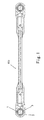
- Figs. 1-5 show a linkage according to a first embodiment of the invention.
- the linkage 100 is formed as an elongated flat member. At least one (two, in this embodiment) of opposite ends of the linkage is provided with a ball socket 3.
- the linkage has a ball socket at one end and has a ball head or the like at the other end.
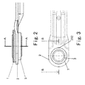
- the configuration of the end of the linkage 100 having the ball socket 3 is shown in detail in Fig. 2 and Fig. 3 , respectively. Both ends of the linkage 100 are configured in the same way. Therefore, only one end of the linkage will be explained below.
- the linkage 100 has a plate-shaped body 2 at the corresponding end.
- the body 2 is mechanically connected to the ball socket 3 by a speed nut 1, as shown in Figs. 2 and 3 .
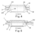
- Fig. 4 and Fig. 5 are sectional views taken through line A-A in Fig. 2 and line B-B in Fig. 3 , respectively.
- the linkage body 2 has a circular through-hole 201 perpendicularly extending from an upper surface to a lower surface of the body 2.
- the ball socket 3 is substantially cylinder-shaped and has a cylindrical segment 34 at one end and a flange 31 at the other end.
- the flange 31 projects radially circumferentially perpendicular to a longitudinal axis of the ball socket.
- the cylindrical segment 34 has an outer diameter equal to or slightly smaller than the inner diameter of the through-hole 201 so that the cylindrical segment 34 can be inserted into the through-hole.
- the cylindrical segment 34 has a height greater than the thickness of the body 2 so as to protrude from the body 2.
- the outer diameter of the flange 31 is greater than the inner diameter of the through-hole 201. In this way, the ball socket 3 is prevented from passing through the through-hole 201. After the cylindrical segment 34 is inserted into the through-hole 201, an upper surface of the flange 31 abuts against the lower surface of the body 2.
- annular groove 33 is formed in an outer surface of the cylindrical segment 34.
- the annular groove 33 extends radially inwards from the outer surface of the cylindrical segment 34 perpendicular to the longitudinal axis of the ball socket.
- a bottom surface of the annular groove 33 is substantially flush with the upper surface of the body 2.
- the bottom surface of the annular groove 33 is slightly higher than or slightly lower than the upper surface of the body.
- the depth, the width and the shape of the annular groove 33 may be varied depending on the concrete structure of the speed nut 1 to be engaged therewith.
- the annular groove 33 shown in Figs. 4-5 has a rectangular cross section, the cross section of annular groove 33 may be in other shapes.
- the annular groove 33 shown in Figs. 4-5 is continuous, it can be alternatively consisted of several segments of discontinuous grooves, depending on the application situation of the linkage and the type of the speed nut 1.
- a slot (not shown) which extends toward the inside of the cylindrical segment 34 and toward the end of the cylindrical segment 34 opposite to the flange 31.
- An inner end 101 of the speed nut 1 is able to be inserted into the slot.
- the slot can be continuous or discontinuous, depending on the type of the speed nut 1.
- the speed nut 1 is preferably produced by a single elastic sheet.
- the speed nut is generally of a disc shape.
- the speed nut is elastically deformed when the inner edge 101 of the speed nut 1 is inserted into the slot and a lower surface of the speed nut 1 presses against the upper surface of the body 2.
- a restoring force caused by the deformation tends to subject the cylindrical segment 34 to an upward force.
- the body 2 is clamped securely between the lower surface of the speed nut 2 and the upper surface of the flange 31, such that a secure connection between the body 2 of the linkage 100 and the ball socket 3 is formed.
- the speed nut 1 is not limited by that shown in Figs. 2-5 and may be provided in other forms, so long as the speed nut is able to elastically snap into the slot of the cylindrical segment 34.
- the speed nut 1 presses against the upper surface of the body 2 and snaps into the slot of an outer wall of the cylindrical segment 34 in an elastic deformed state. A restoring force of the elastic speed nut enables the ball socket to connect with the body tightly.
- the ball socket 3 is configured as a hollow cylindrical shape, having a through-hole therein.
- An inner wall of the through-hole has a segment 35 forming a part of a substantial spherical surface.
- the spherical segment 35 is used to receive a complementary member, which may be a ball head of a second linkage or the like to be connected to the linkage 100. Relative movement of the linkage 100 relative to the second linkage or other members can be achieved by the rotation of an outer surface of the ball head relative to the spherical segment 35 of the ball socket 3 in all direction.
- the ball socket 3 may be formed of a wear-resistant material, or the inner spherical segment 35 of the ball socket 3 may be coated with a wear-resistant material.
- the ball socket 3 may be formed by two pieces, one being the ball socket as shown, and the other being a partial spherical member formed of the wear-resistant material having a certain thickness. The partial spherical member is welded to the spherical segment 35 or assembled with the spherical segment 35 in interference fit manner.
- the ball socket 3 is rotationally fixed to the inner wall of the through-hole of the body 2.
- a radially outwards extending protrusion 38 is provided on the outer surface of the cylindrical segment 34 of the ball socket 2 adjacent the flange 31.
- the lengthwise direction of the projection 38 coincides with the axial direction of the ball socket 2.
- a recess 202 concaved radially inwards is provided in the inner wall of the through-hole 201 of the body 2.
- the recess 202 has a shape matching with the protrusion 38.
- the protrusion 38 When the cylindrical segment 34 of the ball socket 3 is inserted into the through-hole 201 of the body 2, the protrusion 38 is able to engage into the recess 202 to prevent the ball socket 3 from rotating relative to the body 2 during the operation of the linkage.
- the protrusion 38 is provided in the through-hole 201 and correspondingly the recess 202 is provided in the outer surface of the cylindrical segment 34.
- the protrusion 38 and the recess 202 constitute a turn-preventing feature.
- the ball socket 3 After the ball socket 3 is inserted into the though-hole 201, the ball socket 3 is held on the body 2 by the speed nut 1, such that the ball socket 3, the body 2 and the speed nut 1 constitute a single piece and are kept from moving relative to each other.
- the cross section of the through-hole 201 is not limited to a circular shape. It may be square, so long as it matches the shape of the outer surface of cylindrical segment of the ball socket 3. In this case, the outer surface of the cylindrical segment of the ball socket 3 should also be square and the turn-preventing feature shown in Fig. 3 and Fig. 5 can be omitted.
- the turn-preventing feature is not limited to the type mentioned above. It may be any means for preventing the ball socket from rotating relative to the inner wall of the through-hole 201 of the body 2, such as a pin-hole structure, a wedge-wedge structure, or the like. Any form fitting structure can be conceived to obtain a same effect as mentioned above.
- the linkage is consisted of three independent elements, i.e., the body 2, the ball socket 3 and the speed nut 1 of the linkage 100. These elements may be formed separately and then assembled together.
- the ball socket 3 is inserted into the through-hole 201 of the body 2 of the linkage firstly. Then, the ball socket 3 and the body 2 are snapped together by the speed nut 1, which can be rapidly and easily performed.
- the manufacturing process in producing the elements of the linkage independently is improved, the cost is reduced, and the efficiency is increase, compared with overmolding the ball socket and linkage body.
- a second embodiment of the invention will be explained with reference to Figs. 6-9 .
- a ball socket 3 and a body 2 of a linkage 100 according to the second embodiment are connected together by welding, as shown in Fig. 6 .
- the ball socket 3 in the second embodiment is configured as a hollow structure and has a spherical segment 35 therein as in the first embodiment.
- the outer profile of the ball socket 3 in the second embodiment is different from that of the first embodiment, which will be explained in detail.
- Figs. 7 and 8 show an enlarged configuration of only one end of the linkage 100.
- the other end is configured in the same way and thus its description is omitted here.
- the other end of the linkage in the second embodiment may have a ball head or other members rather than the ball socket.
- Fig. 9 is a sectional view taken through line A-A in Fig. 8 .
- the ball socket 3 is also substantially cylinder-shaped and has a cylindrical segment 34 and a flange 31 extending radially outwards from one end of the cylindrical segment 34.
- the radial width of the flange 31 is greater than the flange in the first embodiment. This is because the flange 31 in the first embodiment is only necessary to be sized to prevent the ball socket 3 from passing through the through-hole 201.
- a plurality of projections 36 project from an outer periphery of the flange 31 in the same direction as the cylindrical segment 34 projects.
- the number of the projections 36 is not limited as four, and can be arbitrary, so long as the ball socket is able to be stably connected to the body.
- the projections 36 shown in Figs. 8 and 9 each have a rectangular cross section in a plane perpendicular to the axial direction of the ball socket.
- the cross section of each projection may alternatively be triangular, polygonal or other-shaped.
- the body 2 has a plurality of through-apertures 302 provided at an equal interval in a circumferential direction about the through-hole 201.
- the through-apertures 302 are spaced apart from the through-hole 201.
- the number of the though-apertures 302 corresponds to that of the projections.
- the shape of the through-apertures is not limited as being square as shown in the drawings. It may be circular, triangular or polygonal, so long as the shape of the through-aperture is complementary to the shape of the projection 36.
- the distance between the central axis of the through-aperture 302 and the central axis of the through-hole 201 is equal to the distance between the central axis of the projection 36 and the central axis of the ball socket 3.
- the ball socket 3 is mounted concentrically in the through-hole 201 such that the cylindrical segment 34 is inserted into the through-hole 201 and the projections 36 are engaged in the through-apertures 302.
- the size of the through-aperture 302 should be equal to or slightly greater than the size of the projection so as to facilitate to insert the projection 36.
- the projections 36 When the ball socket 3 is inserted into the through-hole 201 by aligning the projections 36 with the through-apertures 302, the projections 36 are inserted into the through-apertures 302 of the body 2 and protrude from the upper surface of the body 2. Therefore, the height of the projection 36 projecting from the upper surface of the flange 31 is set to be equal to or greater than the thickness of the body 2. In this way, the projections 26 and the through-apertures 302 of the body may be welded together to form a secure connection between the ball socket 3 and the body 2.
- the ball socket 3 is unable to rotate relative to the through-hole 201 of the body 2 due to the secure connection caused by welding. Any turn-preventing feature is unnecessary.
- the structure of the linkage is simplified. Compared with the conventional structure in which the ball socket and the linkage body are connected by overmolding, the ball socket and the linkage body may be formed separately, which leads to a simple manufacturing process. The two components only needed to be welded after manufacturing. The cost-efficiency is increased while the complexity of the molding process is decreased.
Landscapes
- Engineering & Computer Science (AREA)
- Mechanical Engineering (AREA)
- Pivots And Pivotal Connections (AREA)
Abstract
A linkage (100) for a vehicle wiper system, comprising a plate-shaped body (2) at at least one of opposite ends of the linkage and a ball socket (3)mounted in the body (2), wherein the body (2)has a through-hole (201) perpendicularly extending from an upper surface to a lower surface thereof, and the ball socket (3) is configured as a hollow structure and comprises: a cylindrical segment (34) having an outer dimension which allows it to be inserted through the through-hole (201) , and a flange (31) extending radially from one end of the cylindrical segment and having an outer dimension greater than the inner dimension of the through-hole (201), wherein a portion of an inner wall of the ball socket (3) is sphere-shaped so that a ball head of a second linkage used in the vehicle wiper system to be connected to said linkage can be received therein, and wherein the body of said linkage is connected to the ball socket (3) mechanically. With the configuration of the present invention, manufacturing process of the linkage is simplified and manufacturing cost is reduced.
Description
- The invention relates to a vehicle wiper system, especially to a linkage for a vehicle wiper system, which has at at least one end thereof a ball socket mechanically connected to the linkage body.
- In the prior art, various wiper systems are well-known for wiping off the rain water on vehicle windows to clear the field of view of a driver. A conventional wiper system is shown in
Fig. 10 , in which acrank 12 is driven by a motor 10 to rotate in adirection 32. Thecrank 12 is connected to apush rod 16 by a ball joint 14 so that movement of thecrank 12 causes thepush rod 16 to swing. Thepush rod 16 has a distal end opposite the ball joint 14. At the distal end, thepush rod 16 is connected to one end of aswing rod 18 by another ball joint. The other end of theswing rod 18 is connected to ashaft 20 fixed to a vehicle body. Ablade 22 is also connected to theshaft 20, and theblade 22 constitutes as an integrated component together with theswing rod 18, so that theblade 22 and theswing rod 18 rotate or swing together about theshaft 20. Theblade 22 is swung in adirection 34 illustrated inFig. 10 so as to wipe off the rain water on the window. - The wiper system includes two blade assemblies, one of which has been described above. The other blade assembly is configured in the same way. The other blade assembly also includes a
shaft 28 connected to the vehicle body, ablade 30 connected to theshaft 28, and aswing rod 26 connected at one end to theshaft 28. The other end of theswing rod 26 opposite to theshaft 28 is pivotally connected to the end of theswing rod 18 opposite to theshaft 20 by a linkage 24, e.g., by a ball joint. With this configuration, the swing movement of thepush rod 16 is transmitted to theswing rod 26 by the linkage 24. Theblade 30, formed as an integrated component together with theswing rod 26, pivots or swings with theswing rod 26 about theshaft 28, so that the movement of theblade 30 wipes off the rain water on the vehicle windows. The phase relationship between the twoblades shafts - In the wiper system configured above, ball joints may be used at the connections of the respective members, for example, the connection between the
crank 12 and thepush rod 16, the connection between thepush rod 16 and the linkage 24, and the connection between the linkage 24 and theswing rod 26. - In the conventional ball joint, generally one of the linkages has a ball head while the other linkage has a ball socket, the connection of the ball socket and the linkage is formed by overmolding, which results in the complicated molding process and the increased manufacturing cost.
- When the ball socket and the linkage body are connected by overmolding, complicated molds are needed since the shapes of the components are complicated, whether the ball socket is overmolded on the linkage body or the linkage body is overmolded on the ball socket, which results in a complicated molding process, an increased manufacturing cost and a decreased efficiency.
- An object of the invention is to provide a linkage capable of overcoming the above shortcomings, wherein the linkage body and the ball socket are connected mechanically instead of by overmolding. Therefore, manufacturing and assembling are simplified and the manufacture cost is reduced.
- The object is achieved by proposing a linkage for a vehicle wiper system, comprising a plate-shaped body at at least one of opposite ends of the linkage and a ball socket mounted in the body, wherein the body has a through-hole perpendicularly extending from an upper surface to a lower surface thereof, and the ball socket is configured as a hollow structure and comprises: a cylindrical segment having an outer dimension which allows it to be inserted through the through-hole, and a flange extending radially from one end of the cylindrical segment and having an outer dimension greater than the inner dimension of the through-hole, wherein a portion of an inner wall of the ball socket is sphere-shaped so that a ball head of a second linkage used in the vehicle wiper system to be connected to said linkage can be received therein, and wherein the body of said linkage is connected to the ball socket mechanically.
- According to a preferred embodiment, the body of the linkage is connected to the ball socket by a speed nut.
- Wherein a portion of the cylindrical segment of the ball socket projecting beyond the body has an outer surface which is provided with an annular groove extending radially inwards, an upper wall defining the groove is provided with a slot extending toward the end of cylindrical segment opposite to the flange, into which slot the inner edge of the speed nut is inserted, and a lower surface of the speed nut is pressed against the upper surface of the body so that the body is held between the flange of the ball socket and the lower surface of the speed nut under an elastic force of the speed nut.
- Preferably, the speed nut is formed of an elastic material into substantially a disc shape, the inner periphery of which has a tip extending upward for snapping into the slot of the upper wall of the annular groove on the outer surface of the cylindrical segment.
- According to another preferred embodiment, the body of the linkage is connected with the ball socket by welding.
- Wherein the flange of the ball socket has a plurality of projections extending in a direction in which the cylindrical segment extends, the body of the linkage is provided with a plurality of through-apertures around and spaced apart from the through-hole, the cross section of each through-aperture has a shape matching with the cross section of each projection of the ball socket, the cylindrical segment is inserted through the through-hole with the plurality of projections received into the plurality of through-apertures, and the plurality of the projections each have a height equal to or larger than the thickness of the body.
- Preferably, the cross section of the through-hole is circular, and the cross section of the cylindrical segment of the ball socket is also circular.
- Preferably, the outer surface of the cylindrical segment near the flange has a turn-preventing feature for engaging with a turn-preventing feature on the inner wall of the through-hole of the body of the linkage, the turn-preventing features being complementary in shape.
- Wherein the turn-preventing feature in the cylindrical segment is a protrusion projecting radially outwards from the outer surface of the cylindrical segment or a recess concaved inwards from the outer surface, and the turn-preventing feature on the inner wall of the through-hole of the body is a recess depressed radially outwards from the inner wall of the through-hole or a protrusion projecting radially inwards.
- According to another aspect of the invention, a vehicle wiper system comprising at least one linkage described above is provided.
- With the linkage configured above, the ball socket and the linkage body can be formed independently and then assembled together. When assembling, the ball socket is inserted into the through-hole of the linkage body and then the linkage body and the ball socket are connected mechanically (by a speed nut for snapping them together, or by welding). The assembling process can be performed promptly and simply. Compared with producing the ball socket and the linkage body by overmolding, independently forming the components in the present invention, improves the manufacturing process, increase the efficiency, and the cost is decreased.
- Some preferred embodiments of the present invention will be explained in detail with reference to the drawings, which constitute a part of the specification, in which:
-
Fig. 1 schematically illustrates a linkage having a ball socket according to the first embodiment of the invention; -
Fig. 2 is an enlarged side view of one end of the linkage ofFig. 1 ; -
Fig. 3 is a plan view of the end of the linkage ofFig. 2 ; -
Fig. 4 is a cross sectional view taken along line A-A inFig. 2 ; -
Fig. 5 is a cross sectional view taken along line B-B inFig. 3 ; -
Fig. 6 schematically illustrates a linkage having a ball socket according to the second embodiment of the invention; -
Fig. 7 is an enlarged side view of one end of the linkage ofFig. 6 ; -
Fig. 8 is a plan view of the end of the linkage inFig. 7 ; -
Fig. 9 is a cross sectional view taken along line A-A inFig. 8 ; and -
Fig. 10 schematically illustrates a configuration of a conventional vehicle wiper system. - Preferred embodiments according to the invention will be described in detail with reference to the drawings, which are shown schematically and not to scale, wherein the same reference numeral refers to similar components.
-
Figs. 1-5 show a linkage according to a first embodiment of the invention. As shown inFig. 1 , thelinkage 100 is formed as an elongated flat member. At least one (two, in this embodiment) of opposite ends of the linkage is provided with aball socket 3. Alternatively, the linkage has a ball socket at one end and has a ball head or the like at the other end. The configuration of the end of thelinkage 100 having theball socket 3 is shown in detail inFig. 2 and Fig. 3 , respectively. Both ends of thelinkage 100 are configured in the same way. Therefore, only one end of the linkage will be explained below. - The
linkage 100 has a plate-shaped body 2 at the corresponding end. Thebody 2 is mechanically connected to theball socket 3 by aspeed nut 1, as shown inFigs. 2 and 3 . -
Fig. 4 and Fig. 5 are sectional views taken through line A-A inFig. 2 and line B-B inFig. 3 , respectively. As shown in the figures, thelinkage body 2 has a circular through-hole 201 perpendicularly extending from an upper surface to a lower surface of thebody 2. Theball socket 3 is substantially cylinder-shaped and has acylindrical segment 34 at one end and aflange 31 at the other end. Theflange 31 projects radially circumferentially perpendicular to a longitudinal axis of the ball socket. Thecylindrical segment 34 has an outer diameter equal to or slightly smaller than the inner diameter of the through-hole 201 so that thecylindrical segment 34 can be inserted into the through-hole. Thecylindrical segment 34 has a height greater than the thickness of thebody 2 so as to protrude from thebody 2. The outer diameter of theflange 31 is greater than the inner diameter of the through-hole 201. In this way, theball socket 3 is prevented from passing through the through-hole 201. After thecylindrical segment 34 is inserted into the through-hole 201, an upper surface of theflange 31 abuts against the lower surface of thebody 2. - An
annular groove 33 is formed in an outer surface of thecylindrical segment 34. Theannular groove 33 extends radially inwards from the outer surface of thecylindrical segment 34 perpendicular to the longitudinal axis of the ball socket. A bottom surface of theannular groove 33 is substantially flush with the upper surface of thebody 2. However, it is also possible that the bottom surface of theannular groove 33 is slightly higher than or slightly lower than the upper surface of the body. The depth, the width and the shape of theannular groove 33 may be varied depending on the concrete structure of thespeed nut 1 to be engaged therewith. Although theannular groove 33 shown inFigs. 4-5 has a rectangular cross section, the cross section ofannular groove 33 may be in other shapes. Although theannular groove 33 shown inFigs. 4-5 is continuous, it can be alternatively consisted of several segments of discontinuous grooves, depending on the application situation of the linkage and the type of thespeed nut 1. - In an upper wall defining the annular groove 33A, there is a slot (not shown) which extends toward the inside of the
cylindrical segment 34 and toward the end of thecylindrical segment 34 opposite to theflange 31. Aninner end 101 of thespeed nut 1 is able to be inserted into the slot. The slot can be continuous or discontinuous, depending on the type of thespeed nut 1. - The
speed nut 1 is preferably produced by a single elastic sheet. The speed nut is generally of a disc shape. The speed nut is elastically deformed when theinner edge 101 of thespeed nut 1 is inserted into the slot and a lower surface of thespeed nut 1 presses against the upper surface of thebody 2. A restoring force caused by the deformation tends to subject thecylindrical segment 34 to an upward force. In a state that theflange 31 abuts against the lower surface of thebody 2, thebody 2 is clamped securely between the lower surface of thespeed nut 2 and the upper surface of theflange 31, such that a secure connection between thebody 2 of thelinkage 100 and theball socket 3 is formed. - The
speed nut 1 is not limited by that shown inFigs. 2-5 and may be provided in other forms, so long as the speed nut is able to elastically snap into the slot of thecylindrical segment 34. Thespeed nut 1 presses against the upper surface of thebody 2 and snaps into the slot of an outer wall of thecylindrical segment 34 in an elastic deformed state. A restoring force of the elastic speed nut enables the ball socket to connect with the body tightly. - The
ball socket 3 is configured as a hollow cylindrical shape, having a through-hole therein. An inner wall of the through-hole has asegment 35 forming a part of a substantial spherical surface. Thespherical segment 35 is used to receive a complementary member, which may be a ball head of a second linkage or the like to be connected to thelinkage 100. Relative movement of thelinkage 100 relative to the second linkage or other members can be achieved by the rotation of an outer surface of the ball head relative to thespherical segment 35 of theball socket 3 in all direction. - To prolong the duration life of the linkage, the
ball socket 3 may be formed of a wear-resistant material, or the innerspherical segment 35 of theball socket 3 may be coated with a wear-resistant material. Alternatively, theball socket 3 may be formed by two pieces, one being the ball socket as shown, and the other being a partial spherical member formed of the wear-resistant material having a certain thickness. The partial spherical member is welded to thespherical segment 35 or assembled with thespherical segment 35 in interference fit manner. - The
ball socket 3 is rotationally fixed to the inner wall of the through-hole of thebody 2. To this end, a radially outwards extendingprotrusion 38 is provided on the outer surface of thecylindrical segment 34 of theball socket 2 adjacent theflange 31. The lengthwise direction of theprojection 38 coincides with the axial direction of theball socket 2. Accordingly, arecess 202 concaved radially inwards is provided in the inner wall of the through-hole 201 of thebody 2. Therecess 202 has a shape matching with theprotrusion 38. When thecylindrical segment 34 of theball socket 3 is inserted into the through-hole 201 of thebody 2, theprotrusion 38 is able to engage into therecess 202 to prevent theball socket 3 from rotating relative to thebody 2 during the operation of the linkage. Alternatively, it is also possible that theprotrusion 38 is provided in the through-hole 201 and correspondingly therecess 202 is provided in the outer surface of thecylindrical segment 34. Theprotrusion 38 and therecess 202 constitute a turn-preventing feature. - After the
ball socket 3 is inserted into the though-hole 201, theball socket 3 is held on thebody 2 by thespeed nut 1, such that theball socket 3, thebody 2 and thespeed nut 1 constitute a single piece and are kept from moving relative to each other. - The cross section of the through-
hole 201 is not limited to a circular shape. It may be square, so long as it matches the shape of the outer surface of cylindrical segment of theball socket 3. In this case, the outer surface of the cylindrical segment of theball socket 3 should also be square and the turn-preventing feature shown inFig. 3 andFig. 5 can be omitted. - In addition, the turn-preventing feature is not limited to the type mentioned above. It may be any means for preventing the ball socket from rotating relative to the inner wall of the through-
hole 201 of thebody 2, such as a pin-hole structure, a wedge-wedge structure, or the like. Any form fitting structure can be conceived to obtain a same effect as mentioned above. - In the above configuration, the linkage is consisted of three independent elements, i.e., the
body 2, theball socket 3 and thespeed nut 1 of thelinkage 100. These elements may be formed separately and then assembled together. When assembling, theball socket 3 is inserted into the through-hole 201 of thebody 2 of the linkage firstly. Then, theball socket 3 and thebody 2 are snapped together by thespeed nut 1, which can be rapidly and easily performed. The manufacturing process in producing the elements of the linkage independently is improved, the cost is reduced, and the efficiency is increase, compared with overmolding the ball socket and linkage body. - Then, a second embodiment of the invention will be explained with reference to
Figs. 6-9 . Instead of using thespeed nut 1, aball socket 3 and abody 2 of alinkage 100 according to the second embodiment are connected together by welding, as shown inFig. 6 . - The
ball socket 3 in the second embodiment is configured as a hollow structure and has aspherical segment 35 therein as in the first embodiment. The outer profile of theball socket 3 in the second embodiment is different from that of the first embodiment, which will be explained in detail. -
Figs. 7 and 8 show an enlarged configuration of only one end of thelinkage 100. The other end is configured in the same way and thus its description is omitted here. Alternatively, as in the first embodiment, the other end of the linkage in the second embodiment may have a ball head or other members rather than the ball socket. -
Fig. 9 is a sectional view taken through line A-A inFig. 8 . Theball socket 3 is also substantially cylinder-shaped and has acylindrical segment 34 and aflange 31 extending radially outwards from one end of thecylindrical segment 34. In the second embodiment, the radial width of theflange 31 is greater than the flange in the first embodiment. This is because theflange 31 in the first embodiment is only necessary to be sized to prevent theball socket 3 from passing through the through-hole 201. - In
Fig. 9 , a plurality ofprojections 36 project from an outer periphery of theflange 31 in the same direction as thecylindrical segment 34 projects. There are four projections in the present embodiment, as shown inFig. 8 . However, the number of theprojections 36 is not limited as four, and can be arbitrary, so long as the ball socket is able to be stably connected to the body. - The
projections 36 shown inFigs. 8 and9 each have a rectangular cross section in a plane perpendicular to the axial direction of the ball socket. The cross section of each projection may alternatively be triangular, polygonal or other-shaped. - The
body 2 has a plurality of through-apertures 302 provided at an equal interval in a circumferential direction about the through-hole 201. The through-apertures 302 are spaced apart from the through-hole 201. The number of the though-apertures 302 corresponds to that of the projections. There are four through-apertures in the second embodiment. However, fewer or more through-apertures are also possible. The shape of the through-apertures is not limited as being square as shown in the drawings. It may be circular, triangular or polygonal, so long as the shape of the through-aperture is complementary to the shape of theprojection 36. - The distance between the central axis of the through-
aperture 302 and the central axis of the through-hole 201 is equal to the distance between the central axis of theprojection 36 and the central axis of theball socket 3. When assembling, theball socket 3 is mounted concentrically in the through-hole 201 such that thecylindrical segment 34 is inserted into the through-hole 201 and theprojections 36 are engaged in the through-apertures 302. To this end, the size of the through-aperture 302 should be equal to or slightly greater than the size of the projection so as to facilitate to insert theprojection 36. - When the
ball socket 3 is inserted into the through-hole 201 by aligning theprojections 36 with the through-apertures 302, theprojections 36 are inserted into the through-apertures 302 of thebody 2 and protrude from the upper surface of thebody 2. Therefore, the height of theprojection 36 projecting from the upper surface of theflange 31 is set to be equal to or greater than the thickness of thebody 2. In this way, theprojections 26 and the through-apertures 302 of the body may be welded together to form a secure connection between theball socket 3 and thebody 2. - With this configuration, the
ball socket 3 is unable to rotate relative to the through-hole 201 of thebody 2 due to the secure connection caused by welding. Any turn-preventing feature is unnecessary. The structure of the linkage is simplified. Compared with the conventional structure in which the ball socket and the linkage body are connected by overmolding, the ball socket and the linkage body may be formed separately, which leads to a simple manufacturing process. The two components only needed to be welded after manufacturing. The cost-efficiency is increased while the complexity of the molding process is decreased.
Claims (10)
- A linkage for a vehicle wiper system, comprising a plate-shaped body at at least one of opposite ends of the linkage and a ball socket mounted in the body,
wherein the body has a through-hole perpendicularly extending from an upper surface to a lower surface thereof, and the ball socket is configured as a hollow structure and comprises:a cylindrical segment having an outer dimension which allows it to be inserted through the through-hole, anda flange extending radially from one end of the cylindrical segment and having an outer dimension greater than the inner dimension of the through-hole,wherein a portion of an inner wall of the ball socket is sphere-shaped so that a ball head of a second linkage used in the vehicle wiper system to be connected to said linkage can be received therein, and
wherein the body of said linkage is connected to the ball socket mechanically. - The linkage according to claim 1, wherein the body of the linkage is connected to the ball socket by a speed nut.
- The linkage according to claim 2, wherein a portion of the cylindrical segment of the ball socket projecting beyond the body has an outer surface which is provided with an annular groove extending radially inwards, an upper wall defining the groove is provided with a slot extending toward the end of cylindrical segment opposite to the flange, into which slot the inner edge of the speed nut is inserted, and a lower surface of the speed nut is pressed against the upper surface of the body so that the body is held between the flange of the ball socket and the lower surface of the speed nut under an elastic force of the speed nut.
- The linkage according to claim 2 or 3, wherein the speed nut is formed of an elastic material into substantially a disc shape, the inner periphery of which has a tip extending upward for snapping into the slot of the upper wall of the annular groove on the outer surface of the cylindrical segment.
- The linkage according to claim 1, wherein the body of the linkage is connected with the ball socket by welding.
- The linkage according to claim 5, wherein the flange of the ball socket has a plurality of projections extending in a direction in which the cylindrical segment extends, the body of the linkage is provided with a plurality of through-apertures around and spaced radially apart from the through-hole, the cross section of each through-aperture has a shape matching with the cross section of each projection of the ball socket, the cylindrical segment is inserted through the through-hole with the plurality of projections received into the plurality of through-apertures, and the plurality of the projections each have a height equal to or greater than the thickness of the body.
- The linkage according to any one of claims 1 to 6, wherein the cross section of the through-hole is circular, and the cross section of the cylindrical segment of the ball socket is also circular.
- The linkage according to claim 7, wherein the outer surface of the cylindrical segment adjacent the flange has a turn-preventing feature for engaging with a turn-preventing feature on the inner wall of the through-hole of the body of the linkage, the turn-preventing features being complementary in shape.
- The linkage according to claim 8, wherein the turn-preventing feature in the cylindrical segment is a protrusion projecting radially outwards from the outer surface of the cylindrical segment or a recess concaved inwards from the outer surface, and the turn-preventing feature on the inner wall of the through-hole of the body is a recess depressed radially outwards from the inner wall of the through-hole or a protrusion projecting radially inwards.
- A vehicle wiper system comprising at least one linkage according to any one of claims 1 to 9.
Applications Claiming Priority (1)
| Application Number | Priority Date | Filing Date | Title |
|---|---|---|---|
| CN201210397614.9A CN103770750A (en) | 2012-10-18 | 2012-10-18 | Connecting rod for vehicle windscreen wiper |
Publications (1)
| Publication Number | Publication Date |
|---|---|
| EP2722240A2 true EP2722240A2 (en) | 2014-04-23 |
Family
ID=49447963
Family Applications (1)
| Application Number | Title | Priority Date | Filing Date |
|---|---|---|---|
| EP13188909.9A Withdrawn EP2722240A2 (en) | 2012-10-18 | 2013-10-16 | Joint rod for vehicle wiper system |
Country Status (2)
| Country | Link |
|---|---|
| EP (1) | EP2722240A2 (en) |
| CN (1) | CN103770750A (en) |
Cited By (1)
| Publication number | Priority date | Publication date | Assignee | Title |
|---|---|---|---|---|
| WO2022150898A1 (en) * | 2021-01-12 | 2022-07-21 | Valeo Sistemas Automotivos Ltda. | Connecting rod for a windscreen wiper actuating linkage |
Families Citing this family (1)
| Publication number | Priority date | Publication date | Assignee | Title |
|---|---|---|---|---|
| FR3100504B1 (en) * | 2019-09-09 | 2022-04-15 | Valeo Systemes Dessuyage | Crankpin, ball joint and corresponding windshield wiper operating linkage system and method of assembling same |
Family Cites Families (6)
| Publication number | Priority date | Publication date | Assignee | Title |
|---|---|---|---|---|
| DE3344956A1 (en) * | 1983-12-13 | 1985-06-20 | SWF Auto-Electric GmbH, 7120 Bietigheim-Bissingen | Windscreen wiper transmission |
| GB9501207D0 (en) * | 1995-01-21 | 1995-03-15 | Automold Ltd | Mechanical link arms |
| DE19914121B4 (en) * | 1999-03-27 | 2009-10-29 | Volkswagen Ag | Ball joint for drive links |
| DE19940815A1 (en) * | 1999-08-27 | 2001-03-22 | Bosch Gmbh Robert | Wiper system |
| CN2681961Y (en) * | 2004-03-05 | 2005-03-02 | 长安汽车(集团)有限责任公司 | Connecting-rod transmitting apparatus of automobile power driven water wiping device |
| CN202827490U (en) * | 2012-10-18 | 2013-03-27 | 博世汽车部件(长沙)有限公司 | Connecting rod for vehicle windscreen wiper |
-
2012
- 2012-10-18 CN CN201210397614.9A patent/CN103770750A/en active Pending
-
2013
- 2013-10-16 EP EP13188909.9A patent/EP2722240A2/en not_active Withdrawn
Non-Patent Citations (1)
| Title |
|---|
| None |
Cited By (1)
| Publication number | Priority date | Publication date | Assignee | Title |
|---|---|---|---|---|
| WO2022150898A1 (en) * | 2021-01-12 | 2022-07-21 | Valeo Sistemas Automotivos Ltda. | Connecting rod for a windscreen wiper actuating linkage |
Also Published As
| Publication number | Publication date |
|---|---|
| CN103770750A (en) | 2014-05-07 |
Similar Documents
| Publication | Publication Date | Title |
|---|---|---|
| RU2459567C2 (en) | Composite blade-nozzle for food processor | |
| KR20170056456A (en) | Element for a system for connecting a windscreen wiper blade holder to a drive arm | |
| EP2722240A2 (en) | Joint rod for vehicle wiper system | |
| KR20080086866A (en) | wiper | |
| CN103722975A (en) | Wheel assembly | |
| KR101608373B1 (en) | Wiper blade | |
| CN107035762B (en) | Spherical bushing | |
| KR20110044224A (en) | Windscreen wiper drive | |
| CN114364584A (en) | Crank pin, ball joint and corresponding wiper actuation linkage system and method of assembling same | |
| JP2002539014A (en) | Device for fixing the member to the drive shaft of the wiper device | |
| CN107921928B (en) | Drive mechanism for wipers | |
| CN202827490U (en) | Connecting rod for vehicle windscreen wiper | |
| US4347640A (en) | Connector assemblies for connecting wiper blades to wiper arms | |
| KR101351931B1 (en) | Wiper apparatus enhancing ball joint structure | |
| US10723323B2 (en) | Windscreen wiper device | |
| CN107023559B (en) | Ball socket for ball joint | |
| JP2002286018A (en) | Shaft with serration and its manufacturing method, and serration forming tool | |
| CN106061808B (en) | Drive mechanism for windshield wipers | |
| JPS6325367Y2 (en) | ||
| JP6081455B2 (en) | Method and system for permanently fixing screws and windshield wiper motor | |
| KR101511612B1 (en) | Wiper blade | |
| KR101369902B1 (en) | Windshield wiper device in a vehicle | |
| CN216269152U (en) | Windscreen wiper installation device and automobile comprising same | |
| JP2018188138A (en) | Vehicle wiper device | |
| CN120457284A (en) | Windshield wiper module crank and connecting rod ball joint assembly |
Legal Events
| Date | Code | Title | Description |
|---|---|---|---|
| PUAI | Public reference made under article 153(3) epc to a published international application that has entered the european phase |
Free format text: ORIGINAL CODE: 0009012 |
|
| AK | Designated contracting states |
Kind code of ref document: A2 Designated state(s): AL AT BE BG CH CY CZ DE DK EE ES FI FR GB GR HR HU IE IS IT LI LT LU LV MC MK MT NL NO PL PT RO RS SE SI SK SM TR |
|
| AX | Request for extension of the european patent |
Extension state: BA ME |
|
| STAA | Information on the status of an ep patent application or granted ep patent |
Free format text: STATUS: THE APPLICATION IS DEEMED TO BE WITHDRAWN |
|
| 18D | Application deemed to be withdrawn |
Effective date: 20180501 |