EP2722150A1 - Vorrichtung und Verfahren zum Expandieren von Vorformlingen zu Behältnissen - Google Patents
Vorrichtung und Verfahren zum Expandieren von Vorformlingen zu Behältnissen Download PDFInfo
- Publication number
- EP2722150A1 EP2722150A1 EP13189398.4A EP13189398A EP2722150A1 EP 2722150 A1 EP2722150 A1 EP 2722150A1 EP 13189398 A EP13189398 A EP 13189398A EP 2722150 A1 EP2722150 A1 EP 2722150A1
- Authority
- EP
- European Patent Office
- Prior art keywords
- medium
- actuator
- blow mold
- compressor piston
- container
- Prior art date
- Legal status (The legal status is an assumption and is not a legal conclusion. Google has not performed a legal analysis and makes no representation as to the accuracy of the status listed.)
- Granted
Links
- 238000000034 method Methods 0.000 title claims abstract description 85
- 230000008569 process Effects 0.000 claims abstract description 71
- 238000004891 communication Methods 0.000 claims abstract description 5
- 239000012530 fluid Substances 0.000 claims description 9
- 230000000694 effects Effects 0.000 claims description 5
- 230000008054 signal transmission Effects 0.000 claims description 5
- 238000005516 engineering process Methods 0.000 claims description 3
- 230000003134 recirculating effect Effects 0.000 abstract description 4
- 230000006835 compression Effects 0.000 description 23
- 238000007906 compression Methods 0.000 description 23
- 230000033001 locomotion Effects 0.000 description 22
- 238000007664 blowing Methods 0.000 description 18
- 238000010586 diagram Methods 0.000 description 10
- 239000003990 capacitor Substances 0.000 description 7
- 239000007788 liquid Substances 0.000 description 5
- 238000000071 blow moulding Methods 0.000 description 4
- 238000011049 filling Methods 0.000 description 4
- 230000009969 flowable effect Effects 0.000 description 4
- 239000007789 gas Substances 0.000 description 3
- 230000001954 sterilising effect Effects 0.000 description 3
- 239000007864 aqueous solution Substances 0.000 description 2
- 230000003111 delayed effect Effects 0.000 description 2
- 238000001035 drying Methods 0.000 description 2
- 238000010438 heat treatment Methods 0.000 description 2
- 238000005086 pumping Methods 0.000 description 2
- 238000011084 recovery Methods 0.000 description 2
- 238000004659 sterilization and disinfection Methods 0.000 description 2
- XLYOFNOQVPJJNP-UHFFFAOYSA-N water Substances O XLYOFNOQVPJJNP-UHFFFAOYSA-N 0.000 description 2
- 230000009471 action Effects 0.000 description 1
- 235000013361 beverage Nutrition 0.000 description 1
- 239000000470 constituent Substances 0.000 description 1
- 238000010276 construction Methods 0.000 description 1
- 238000001816 cooling Methods 0.000 description 1
- 230000008878 coupling Effects 0.000 description 1
- 238000010168 coupling process Methods 0.000 description 1
- 238000005859 coupling reaction Methods 0.000 description 1
- 230000009849 deactivation Effects 0.000 description 1
- 230000001419 dependent effect Effects 0.000 description 1
- 230000000249 desinfective effect Effects 0.000 description 1
- 238000011161 development Methods 0.000 description 1
- 230000018109 developmental process Effects 0.000 description 1
- 238000006073 displacement reaction Methods 0.000 description 1
- 230000000977 initiatory effect Effects 0.000 description 1
- 238000002372 labelling Methods 0.000 description 1
- 239000000314 lubricant Substances 0.000 description 1
- 238000004519 manufacturing process Methods 0.000 description 1
- 239000000203 mixture Substances 0.000 description 1
- 238000013021 overheating Methods 0.000 description 1
- 238000004806 packaging method and process Methods 0.000 description 1
- 238000012545 processing Methods 0.000 description 1
- 230000001902 propagating effect Effects 0.000 description 1
- 238000007789 sealing Methods 0.000 description 1
- 238000007493 shaping process Methods 0.000 description 1
- 238000012546 transfer Methods 0.000 description 1
- 230000007704 transition Effects 0.000 description 1
- 230000001960 triggered effect Effects 0.000 description 1
- 239000002918 waste heat Substances 0.000 description 1
Images

Classifications
-
- B—PERFORMING OPERATIONS; TRANSPORTING
- B29—WORKING OF PLASTICS; WORKING OF SUBSTANCES IN A PLASTIC STATE IN GENERAL
- B29C—SHAPING OR JOINING OF PLASTICS; SHAPING OF MATERIAL IN A PLASTIC STATE, NOT OTHERWISE PROVIDED FOR; AFTER-TREATMENT OF THE SHAPED PRODUCTS, e.g. REPAIRING
- B29C49/00—Blow-moulding, i.e. blowing a preform or parison to a desired shape within a mould; Apparatus therefor
- B29C49/42—Component parts, details or accessories; Auxiliary operations
- B29C49/78—Measuring, controlling or regulating
- B29C49/783—Measuring, controlling or regulating blowing pressure
-
- B—PERFORMING OPERATIONS; TRANSPORTING
- B29—WORKING OF PLASTICS; WORKING OF SUBSTANCES IN A PLASTIC STATE IN GENERAL
- B29C—SHAPING OR JOINING OF PLASTICS; SHAPING OF MATERIAL IN A PLASTIC STATE, NOT OTHERWISE PROVIDED FOR; AFTER-TREATMENT OF THE SHAPED PRODUCTS, e.g. REPAIRING
- B29C49/00—Blow-moulding, i.e. blowing a preform or parison to a desired shape within a mould; Apparatus therefor
- B29C49/08—Biaxial stretching during blow-moulding
- B29C49/10—Biaxial stretching during blow-moulding using mechanical means for prestretching
- B29C49/12—Stretching rods
-
- B—PERFORMING OPERATIONS; TRANSPORTING
- B29—WORKING OF PLASTICS; WORKING OF SUBSTANCES IN A PLASTIC STATE IN GENERAL
- B29C—SHAPING OR JOINING OF PLASTICS; SHAPING OF MATERIAL IN A PLASTIC STATE, NOT OTHERWISE PROVIDED FOR; AFTER-TREATMENT OF THE SHAPED PRODUCTS, e.g. REPAIRING
- B29C49/00—Blow-moulding, i.e. blowing a preform or parison to a desired shape within a mould; Apparatus therefor
- B29C49/42—Component parts, details or accessories; Auxiliary operations
- B29C49/4236—Drive means
- B29C49/42362—Electric drive means, e.g. servomotors
-
- B—PERFORMING OPERATIONS; TRANSPORTING
- B29—WORKING OF PLASTICS; WORKING OF SUBSTANCES IN A PLASTIC STATE IN GENERAL
- B29C—SHAPING OR JOINING OF PLASTICS; SHAPING OF MATERIAL IN A PLASTIC STATE, NOT OTHERWISE PROVIDED FOR; AFTER-TREATMENT OF THE SHAPED PRODUCTS, e.g. REPAIRING
- B29C49/00—Blow-moulding, i.e. blowing a preform or parison to a desired shape within a mould; Apparatus therefor
- B29C49/42—Component parts, details or accessories; Auxiliary operations
- B29C49/4236—Drive means
- B29C49/4237—Pneumatic drive means
-
- B—PERFORMING OPERATIONS; TRANSPORTING
- B29—WORKING OF PLASTICS; WORKING OF SUBSTANCES IN A PLASTIC STATE IN GENERAL
- B29C—SHAPING OR JOINING OF PLASTICS; SHAPING OF MATERIAL IN A PLASTIC STATE, NOT OTHERWISE PROVIDED FOR; AFTER-TREATMENT OF THE SHAPED PRODUCTS, e.g. REPAIRING
- B29C49/00—Blow-moulding, i.e. blowing a preform or parison to a desired shape within a mould; Apparatus therefor
- B29C49/42—Component parts, details or accessories; Auxiliary operations
- B29C49/48—Moulds
- B29C2049/4856—Mounting, exchanging or centering moulds or parts thereof
-
- B—PERFORMING OPERATIONS; TRANSPORTING
- B29—WORKING OF PLASTICS; WORKING OF SUBSTANCES IN A PLASTIC STATE IN GENERAL
- B29C—SHAPING OR JOINING OF PLASTICS; SHAPING OF MATERIAL IN A PLASTIC STATE, NOT OTHERWISE PROVIDED FOR; AFTER-TREATMENT OF THE SHAPED PRODUCTS, e.g. REPAIRING
- B29C49/00—Blow-moulding, i.e. blowing a preform or parison to a desired shape within a mould; Apparatus therefor
- B29C49/42—Component parts, details or accessories; Auxiliary operations
- B29C49/78—Measuring, controlling or regulating
- B29C49/783—Measuring, controlling or regulating blowing pressure
- B29C2049/7831—Measuring, controlling or regulating blowing pressure characterised by pressure values or ranges
-
- B—PERFORMING OPERATIONS; TRANSPORTING
- B29—WORKING OF PLASTICS; WORKING OF SUBSTANCES IN A PLASTIC STATE IN GENERAL
- B29C—SHAPING OR JOINING OF PLASTICS; SHAPING OF MATERIAL IN A PLASTIC STATE, NOT OTHERWISE PROVIDED FOR; AFTER-TREATMENT OF THE SHAPED PRODUCTS, e.g. REPAIRING
- B29C49/00—Blow-moulding, i.e. blowing a preform or parison to a desired shape within a mould; Apparatus therefor
- B29C49/42—Component parts, details or accessories; Auxiliary operations
- B29C49/78—Measuring, controlling or regulating
- B29C2049/788—Controller type or interface
- B29C2049/78815—Controller type or interface using wireless transmission
-
- B—PERFORMING OPERATIONS; TRANSPORTING
- B29—WORKING OF PLASTICS; WORKING OF SUBSTANCES IN A PLASTIC STATE IN GENERAL
- B29C—SHAPING OR JOINING OF PLASTICS; SHAPING OF MATERIAL IN A PLASTIC STATE, NOT OTHERWISE PROVIDED FOR; AFTER-TREATMENT OF THE SHAPED PRODUCTS, e.g. REPAIRING
- B29C2949/00—Indexing scheme relating to blow-moulding
- B29C2949/07—Preforms or parisons characterised by their configuration
- B29C2949/0715—Preforms or parisons characterised by their configuration the preform having one end closed
-
- B—PERFORMING OPERATIONS; TRANSPORTING
- B29—WORKING OF PLASTICS; WORKING OF SUBSTANCES IN A PLASTIC STATE IN GENERAL
- B29C—SHAPING OR JOINING OF PLASTICS; SHAPING OF MATERIAL IN A PLASTIC STATE, NOT OTHERWISE PROVIDED FOR; AFTER-TREATMENT OF THE SHAPED PRODUCTS, e.g. REPAIRING
- B29C49/00—Blow-moulding, i.e. blowing a preform or parison to a desired shape within a mould; Apparatus therefor
- B29C49/02—Combined blow-moulding and manufacture of the preform or the parison
- B29C49/06—Injection blow-moulding
-
- B—PERFORMING OPERATIONS; TRANSPORTING
- B29—WORKING OF PLASTICS; WORKING OF SUBSTANCES IN A PLASTIC STATE IN GENERAL
- B29C—SHAPING OR JOINING OF PLASTICS; SHAPING OF MATERIAL IN A PLASTIC STATE, NOT OTHERWISE PROVIDED FOR; AFTER-TREATMENT OF THE SHAPED PRODUCTS, e.g. REPAIRING
- B29C49/00—Blow-moulding, i.e. blowing a preform or parison to a desired shape within a mould; Apparatus therefor
- B29C49/42—Component parts, details or accessories; Auxiliary operations
- B29C49/4236—Drive means
- B29C49/42372—Hydraulic drive means
-
- B—PERFORMING OPERATIONS; TRANSPORTING
- B29—WORKING OF PLASTICS; WORKING OF SUBSTANCES IN A PLASTIC STATE IN GENERAL
- B29C—SHAPING OR JOINING OF PLASTICS; SHAPING OF MATERIAL IN A PLASTIC STATE, NOT OTHERWISE PROVIDED FOR; AFTER-TREATMENT OF THE SHAPED PRODUCTS, e.g. REPAIRING
- B29C49/00—Blow-moulding, i.e. blowing a preform or parison to a desired shape within a mould; Apparatus therefor
- B29C49/42—Component parts, details or accessories; Auxiliary operations
- B29C49/42414—Treatment of preforms, e.g. cleaning or spraying water for improved heat transfer
- B29C49/42416—Purging or cleaning the preforms
- B29C49/42418—Purging or cleaning the preforms for sterilizing
-
- B—PERFORMING OPERATIONS; TRANSPORTING
- B29—WORKING OF PLASTICS; WORKING OF SUBSTANCES IN A PLASTIC STATE IN GENERAL
- B29C—SHAPING OR JOINING OF PLASTICS; SHAPING OF MATERIAL IN A PLASTIC STATE, NOT OTHERWISE PROVIDED FOR; AFTER-TREATMENT OF THE SHAPED PRODUCTS, e.g. REPAIRING
- B29C49/00—Blow-moulding, i.e. blowing a preform or parison to a desired shape within a mould; Apparatus therefor
- B29C49/42—Component parts, details or accessories; Auxiliary operations
- B29C49/4252—Auxiliary operations prior to the blow-moulding operation not otherwise provided for
-
- B—PERFORMING OPERATIONS; TRANSPORTING
- B29—WORKING OF PLASTICS; WORKING OF SUBSTANCES IN A PLASTIC STATE IN GENERAL
- B29C—SHAPING OR JOINING OF PLASTICS; SHAPING OF MATERIAL IN A PLASTIC STATE, NOT OTHERWISE PROVIDED FOR; AFTER-TREATMENT OF THE SHAPED PRODUCTS, e.g. REPAIRING
- B29C49/00—Blow-moulding, i.e. blowing a preform or parison to a desired shape within a mould; Apparatus therefor
- B29C49/42—Component parts, details or accessories; Auxiliary operations
- B29C49/4273—Auxiliary operations after the blow-moulding operation not otherwise provided for
-
- B—PERFORMING OPERATIONS; TRANSPORTING
- B29—WORKING OF PLASTICS; WORKING OF SUBSTANCES IN A PLASTIC STATE IN GENERAL
- B29C—SHAPING OR JOINING OF PLASTICS; SHAPING OF MATERIAL IN A PLASTIC STATE, NOT OTHERWISE PROVIDED FOR; AFTER-TREATMENT OF THE SHAPED PRODUCTS, e.g. REPAIRING
- B29C49/00—Blow-moulding, i.e. blowing a preform or parison to a desired shape within a mould; Apparatus therefor
- B29C49/42—Component parts, details or accessories; Auxiliary operations
- B29C49/4273—Auxiliary operations after the blow-moulding operation not otherwise provided for
- B29C49/428—Joining
- B29C49/42802—Joining a closure or a sealing foil to the article or pincing the opening
-
- B—PERFORMING OPERATIONS; TRANSPORTING
- B29—WORKING OF PLASTICS; WORKING OF SUBSTANCES IN A PLASTIC STATE IN GENERAL
- B29C—SHAPING OR JOINING OF PLASTICS; SHAPING OF MATERIAL IN A PLASTIC STATE, NOT OTHERWISE PROVIDED FOR; AFTER-TREATMENT OF THE SHAPED PRODUCTS, e.g. REPAIRING
- B29C49/00—Blow-moulding, i.e. blowing a preform or parison to a desired shape within a mould; Apparatus therefor
- B29C49/42—Component parts, details or accessories; Auxiliary operations
- B29C49/4273—Auxiliary operations after the blow-moulding operation not otherwise provided for
- B29C49/42808—Filling the article
-
- B—PERFORMING OPERATIONS; TRANSPORTING
- B29—WORKING OF PLASTICS; WORKING OF SUBSTANCES IN A PLASTIC STATE IN GENERAL
- B29C—SHAPING OR JOINING OF PLASTICS; SHAPING OF MATERIAL IN A PLASTIC STATE, NOT OTHERWISE PROVIDED FOR; AFTER-TREATMENT OF THE SHAPED PRODUCTS, e.g. REPAIRING
- B29C49/00—Blow-moulding, i.e. blowing a preform or parison to a desired shape within a mould; Apparatus therefor
- B29C49/42—Component parts, details or accessories; Auxiliary operations
- B29C49/4273—Auxiliary operations after the blow-moulding operation not otherwise provided for
- B29C49/4282—Purging or cleaning the article
- B29C49/42822—Sterilizing the article
-
- B—PERFORMING OPERATIONS; TRANSPORTING
- B29—WORKING OF PLASTICS; WORKING OF SUBSTANCES IN A PLASTIC STATE IN GENERAL
- B29C—SHAPING OR JOINING OF PLASTICS; SHAPING OF MATERIAL IN A PLASTIC STATE, NOT OTHERWISE PROVIDED FOR; AFTER-TREATMENT OF THE SHAPED PRODUCTS, e.g. REPAIRING
- B29C49/00—Blow-moulding, i.e. blowing a preform or parison to a desired shape within a mould; Apparatus therefor
- B29C49/42—Component parts, details or accessories; Auxiliary operations
- B29C49/4284—Means for recycling or reusing auxiliaries or materials, e.g. blowing fluids or energy
- B29C49/42845—Recycling or reusing of fluid, e.g. pressure
- B29C49/42855—Blowing fluids, e.g. reducing fluid consumption
-
- B—PERFORMING OPERATIONS; TRANSPORTING
- B29—WORKING OF PLASTICS; WORKING OF SUBSTANCES IN A PLASTIC STATE IN GENERAL
- B29C—SHAPING OR JOINING OF PLASTICS; SHAPING OF MATERIAL IN A PLASTIC STATE, NOT OTHERWISE PROVIDED FOR; AFTER-TREATMENT OF THE SHAPED PRODUCTS, e.g. REPAIRING
- B29C49/00—Blow-moulding, i.e. blowing a preform or parison to a desired shape within a mould; Apparatus therefor
- B29C49/42—Component parts, details or accessories; Auxiliary operations
- B29C49/4284—Means for recycling or reusing auxiliaries or materials, e.g. blowing fluids or energy
- B29C49/4286—Recycling or reusing of heat energy
-
- B—PERFORMING OPERATIONS; TRANSPORTING
- B29—WORKING OF PLASTICS; WORKING OF SUBSTANCES IN A PLASTIC STATE IN GENERAL
- B29C—SHAPING OR JOINING OF PLASTICS; SHAPING OF MATERIAL IN A PLASTIC STATE, NOT OTHERWISE PROVIDED FOR; AFTER-TREATMENT OF THE SHAPED PRODUCTS, e.g. REPAIRING
- B29C49/00—Blow-moulding, i.e. blowing a preform or parison to a desired shape within a mould; Apparatus therefor
- B29C49/42—Component parts, details or accessories; Auxiliary operations
- B29C49/4284—Means for recycling or reusing auxiliaries or materials, e.g. blowing fluids or energy
- B29C49/4287—Means for recycling or reusing auxiliaries or materials, e.g. blowing fluids or energy for use outside the blow-moulding apparatus, e.g. generating power or as pressurized plant air
-
- B—PERFORMING OPERATIONS; TRANSPORTING
- B29—WORKING OF PLASTICS; WORKING OF SUBSTANCES IN A PLASTIC STATE IN GENERAL
- B29C—SHAPING OR JOINING OF PLASTICS; SHAPING OF MATERIAL IN A PLASTIC STATE, NOT OTHERWISE PROVIDED FOR; AFTER-TREATMENT OF THE SHAPED PRODUCTS, e.g. REPAIRING
- B29C49/00—Blow-moulding, i.e. blowing a preform or parison to a desired shape within a mould; Apparatus therefor
- B29C49/42—Component parts, details or accessories; Auxiliary operations
- B29C49/58—Blowing means
-
- Y—GENERAL TAGGING OF NEW TECHNOLOGICAL DEVELOPMENTS; GENERAL TAGGING OF CROSS-SECTIONAL TECHNOLOGIES SPANNING OVER SEVERAL SECTIONS OF THE IPC; TECHNICAL SUBJECTS COVERED BY FORMER USPC CROSS-REFERENCE ART COLLECTIONS [XRACs] AND DIGESTS
- Y02—TECHNOLOGIES OR APPLICATIONS FOR MITIGATION OR ADAPTATION AGAINST CLIMATE CHANGE
- Y02P—CLIMATE CHANGE MITIGATION TECHNOLOGIES IN THE PRODUCTION OR PROCESSING OF GOODS
- Y02P70/00—Climate change mitigation technologies in the production process for final industrial or consumer products
- Y02P70/10—Greenhouse gas [GHG] capture, material saving, heat recovery or other energy efficient measures, e.g. motor control, characterised by manufacturing processes, e.g. for rolling metal or metal working
Definitions
- the present invention relates to an apparatus and a method for expanding preforms into containers within a blow mold by means of a pressurized pneumatic medium, according to the preambles of claims 1 and 7.
- Devices and methods for expanding containers are used for example in the manufacturing industry of beverage containers application, wherein by means of appropriate treatment facilities, inter alia, primarily from a preform made of plastic within a blow mold a corresponding also made of plastic container is inflated or expanded.
- a corresponding preform is introduced into an inner region of a blowing mold, which is usually designed in two parts, which has at least one cavity in its inner region, which serves for the shaping of the later expanded container.
- the blow mold surrounds the preform in full, at least around its lower region, wherein the mouth region of the preform, which has a correspondingly formed or cut internal or external thread, at least partially protrude from the blow mold or at least not within the region of the cavity Blow mold is introduced so that an expansion and in particular a deformation of the mouth region of the preform during its expansion process is avoided.
- blowing nozzle which can be placed in particular on an opening region of the preform, through which a pressurized pneumatic or gaseous, flowable medium, such as a sterilizing gas or air in the interior of the blow mold and thus in the interior of the container to be expanded or to be expanded Vorforrmlings is introduced, inflation or stretch blow molding of the preform takes place to an expanded container.
- a pressurized pneumatic or gaseous, flowable medium such as a sterilizing gas or air in the interior of the blow mold and thus in the interior of the container to be expanded or to be expanded Vorforrmlings
- a stretching rod is additionally preferably moved from an inlet of the blow mold, which is preferably in the region of the mouth region of the preform, to a bottom region of the blow mold and accordingly of the continuously expanding container, for which purpose, depending on the positioning or storage of the blow mold. the movement takes place essentially along a longitudinal axis of the container and consequently essentially in vertical or perpendicular direction to the horizontal plane.
- blow mold including the blowing nozzle
- the blow mold to move with the preform to be expanded in the direction of the stretching rod and / or the blowing nozzle, so that the movement of the blow mold itself, which is comparable to the movement of the stretching rod substantially vertical or perpendicular direction to the horizontal plane, according to which the stretching levels are moved through the inner region of the preform to be expanded, so that the introduced compressed air can be applied substantially uniformly to the inner regions of the preform, whereby a deformation of the wall element required for expansion of the preform is achieved. and ground area is caused.
- both the stretching rod and / or the blowing nozzle and the blow mold itself move towards and / or away from each other at respectively defined speeds during the expansion process of the preform.
- a preform can be treated by means of preheating, heating, disinfecting, drying and / or expanding or expanded blowing, while an expanded container can be disinfected, for example with the treatment steps: Drying, filling, labeling, sealing with container closures and / or packaging can be treated.
- blow molds required for expansion are preferably mounted on a transporting element, such as e.g. a transport wheel or star wheel are arranged substantially identically spaced from each other and are consequently also moved by the rotation of the wheel about its central axis of rotation corresponding to this axis of rotation at a defined speed.
- a transporting element such as e.g. a transport wheel or star wheel are arranged substantially identically spaced from each other and are consequently also moved by the rotation of the wheel about its central axis of rotation corresponding to this axis of rotation at a defined speed.
- the preforms along a predetermined transport path, which is in particular perpendicular to the direction of movement of the tuyere and / or the stretch rod and / or the blow mold transported.
- the preforms or containers to be expanded are preferably supplied to the blow molds with at least one further transport device, namely a feed transport device of the transport device, wherein this feed transport device of the preforms to be expanded is, for example, a conveyor belt or likewise a transport wheel.
- the expanded containers are preferably taken over by the blow molding conveyor by means of at least one corresponding discharge conveyor and, for example, to a subsequent processing station, e.g. a disinfection system or a filling system for filling the container, etc. supplied.
- a subsequent processing station e.g. a disinfection system or a filling system for filling the container, etc. supplied.
- the containers to be expanded are transferred.
- blowing pressures of, for example, about 35 to 40 bar used to ensure in particular that the plastic of the preform or the wall of the preform is so expanded or deformed that this in All defined areas of the cavity of the blow mold is introduced or pressed, so that a container in a defined manner expanded can be generated.
- the required blowing pressure depends inter alia on the composition of the plastic, the heating of the preform, the wall thickness of the preform, etc. from.
- the generation of the required for expansion of the preform blast air or compressed air is known to be very energy-intensive, in particular due to the heat generated in the compressor, which compresses the blast air to a defined pressure.
- the resulting waste heat is discharged at high pressure compressors mostly via a correspondingly arranged cooler to the outside of the system, for example, to avoid overheating of the compressor and thus damage it.
- the object of the present invention is to provide an apparatus and a method in which the energy expended for compressing the blowing air or the air or the pneumatic medium is recovered to the greatest possible extent during a relaxation process following the expansion process can.
- the device according to the invention for expanding preforms into containers within a blow mold by means of a pressurized pneumatic medium has in particular a compressor piston device for compressing the pneumatic medium, which is in flow communication with the blow mold, in order to introduce a volume flow of the pneumatic medium into an inner region of the blow mold ,
- the compressor piston device which in this case primarily a compression chamber or a pressure chamber, within which the pneumatic medium is compressed, and at least one piston element for compressing the pneumatic medium within the compression chamber, is primarily directly or directly or indirectly via corresponding connecting lines for conducting the Compressed air connected to the blow mold to press the compressed air blown or the compressed pneumatic medium primarily without cooling in the interior of the blow mold and thus in the interior of the preform, so that at least by the direct transition of the compressed pneumatic medium from the compressor piston device to the blow mold only a small proportion of heat is given off to the environment, which in this case already an energy saving compared to known blowing method is achieved.
- the compressor piston device is preferably arranged directly or at least indirectly via corresponding connecting lines to the respective blowing stations and a plurality of such compressor piston devices are preferably provided.
- one compressor piston device is provided per forming or blowing station.
- the device according to the invention has an activatable by a hydraulic medium actuator means which interacts with at least one element of the compressor piston means to drive during an expansion process of the container, the compressor piston means for compressing the pneumatic medium and during a expansion process temporally subsequent relaxation process due to the back flowing Volumetric flow of the pneumatic medium to be driven in the compressor piston device itself.
- the actuator device can preferably also be at least one section or a component of the compressor piston device and in particular at least one component of the piston element of the compressor piston device.
- the actuator device and the compressor piston device represent two mutually different devices, which are so mechanically or also signal transmission technology connected to each other such that movement of the actuator piston device and in particular the piston member of the compressor piston device or by a movement the compressor piston device and in particular the piston element of the compressor piston device and a movement of the actuator device is made possible.
- the pneumatic medium is preferably a gaseous medium such as compressed air or a compressible gas such as a sterilizing gas or the like.
- the actuator device itself mainly has an actuator piston element and an actuator medium space, within which primarily a hydraulic medium is introduced in order to move the actuator piston element.
- the piston element of the compressor piston device that is operatively connected to this actuator piston element is also moved, so that during an expansion process of the container to be expanded, the piston element of the compressor piston device compresses a pneumatic medium located in the compression space. which is then transferred primarily to a tuyere (a blow mold) or a blow mold.
- the actuator device or at least one component of the actuator device receives an electronic signal from, for example, a control device and converts it into corresponding mechanical movements, in order thereby to drive or drive the compressor piston device.
- At least one storage container having a hydraulic medium is connected to the actuator device via at least one connecting line in order to provide the actuator device with the hydraulic medium at least temporarily and at least partially.
- the hydraulic medium is preferably a liquid and in particular flowable medium, such as water, an aqueous solution or a lubricant, such as oil or the like.
- the device has a total of two or more storage containers to store the hydraulic medium and to pass over the connecting lines for transporting the hydraulic medium to the actuator device.
- preferably only one of the storage containers is opened via corresponding valves in order to be able to provide the hydraulic medium to the actuator device.
- At least one pump device is operatively connected to the storage container in order at least temporarily to effect a transport of the hydraulic medium from the storage container to the actuator device.
- At least one prime mover is operatively connected to the pump device in order to drive the pump device and / or to be driven or at least relieved by an activated pump device.
- the prime mover which preferably alternately acts as an electric drive motor and as an electric drive generator, preferably via a shaft substantially directly and / or via coupling devices, such as intermeshing gears, which to corresponding shafts of the prime mover and the Pump means are arranged, substantially indirectly operatively connected to the pump means, so that a rotational movement of the rotor of the drive means causes a rotational movement of the rotor of the pump means to effect a pumping of the hydraulic medium from one of the storage containers through the connecting lines in the direction of the actuator device.
- a control device is connected to the drive machine and / or at least one valve device arranged between the storage container and the actuator device so as to actuate the drive machine and / or the valve device at least temporarily as needed.
- this control means is a control means, i. It is advantageous to have a control loop.
- a valve device is activated substantially simultaneously with a drive machine in order to allow a flow of a volume flow of hydraulic medium from the at least one Vorrast therenis in the direction of the actuator device, provided that the drive machine acts as a drive motor and controls the pump device. Accordingly, the valve device can be closed when neither an expansion process nor a relaxation process takes place, that is, especially when no treatment of a container takes place. The valve device is also open during the relaxation process, i. after the container has been expanded and the injected compressed air in the blow mold escapes from this again.
- the pneumatic medium escaping from the blow mold is guided back to the compressor piston device and in particular into the compression chamber of the compressor piston device, in which the pneumatic medium propagates and consequently moves the piston element out of the compression chamber.
- the piston element is subjected to no mechanical force and can therefore be moved substantially undisturbed by the back-propagating in the compression space pneumatic medium.
- the movement of the piston element preferably also activates the actuator device and, in particular, moves the actuator piston element in such a way that a hydraulic medium located in the actuator medium space moves out of this space and via the connection lines and the open valve devices in the direction of the latching container, from which the hydraulic actuator Medium was removed during the expansion process is transported.
- the hydraulic medium also flows through it such that the pump device, that this is excited or activated by the volume flow of the returning hydraulic medium, and consequently also a drive machine operatively connected to the pump device, which now acts as a drive generator, is driven.
- a method for expanding preforms to containers within a blow mold by means of a pressurized pneumatic medium is claimed, according to which during a expansion process for expanding the container, a compressor piston device for compressing the pneumatic medium by one with a hydraulic medium and operated with at least one element of the compressor piston device interacting actuator device is driven to transport the pneumatic medium in an inner region of the blow mold and in which during a relaxation process subsequent expansion process, the pneumatic medium is returned to the compressor piston device, whereby the actuator device is caused to a return of the hydraulic medium ,
- the hydraulic or liquid and preferably flowable medium which is, for example, a sterilization medium, water, an aqueous solution or an oil
- a pump device which is in operative connection with a drive machine, primarily during the expansion process , so that by a drive of the pump means by means of the volume flow of the returning hydraulic medium and the drive machine is operated in the form of a drive generator.
- the pump device activated by a volume flow of the hydraulic medium flowing through drives the drive machine as a drive generator for generating electrical energy and / or conveys the fluid into a pressurized container.
- the prime mover which is primarily an electric drive machine, which can act as a drive motor or as a drive generator, preferably with an electrical circuit and in particular with an electrical DC link, which preferably has at least one capacitor or a similar storage element for storing electrical energy connected , Consequently, the by the Drive machine generated electrical energy during a relaxation process in the electrical circuit and fed primarily into the intermediate circuit of the electric circuit, whereby, for example, the capacitor can be charged.
- This injected electrical energy is at least partially and at least temporarily during an expansion process, for example, another to be expanded preform of the electric drive machine again to drive them in the form of a drive motor in turn such or activate, that the rotor of the prime mover drives the rotor of the pump device in order to effect removal of the hydraulic medium from a storage container and the conduction of the hydraulic medium from the storage container to the actuator device.
- the individual devices according to the invention have a common circuit, so that the energy flows, i. the currents of the electrical energy generated by the drive machine in the form of an electric drive generator of the preferably juxtaposed in series devices according to the invention substantially compensate, such an arrangement primarily for rotary with a plurality of blowing stations and therefore a plurality of inventive devices, preferably each blow station a separate device according to the invention is associated, is advantageous.
- the container treatment processes and in particular the process of expanding the preform into a container are coordinated or delayed such that while, for example, a first device according to the invention receives electrical energy from the circuit, for example to begin an expansion process, a second device according to the invention For example, even at the end of the expansion process itself or is in particular shortly before the initiation of the subsequent relaxation process, so that this second device according to the invention does not have to draw electrical energy from the circuit, nor supplies electrical power to the circuit, while for example a third device 10 according to the invention already is relatively at the end of the relaxation process and substantially simultaneously with the beginning of the expansion process of the first device, the expansion process and thus a feed s has completed of electrical energy in the power grid or the circuit.
- the device has an electrical storage means, in particular for storing electrical energy generated by the drive machine.
- This storage means may be, for example, a battery or a capacitor.
- This storage means can be integrated in a DC link.
- At least one control device controls the drive machine and / or at least one valve device arranged between at least one storage container for storing the hydraulic medium and the actuator device, in order to discharge the hydraulic medium from the storage container to the actuator device during the expansion process and during the expansion process To allow relaxation process of the actuator device to the storage container.
- control device which may be connected, for example, wirelessly or via corresponding connection cable with the drive unit and / or the valve device, so signal transmission technology connected to the prime mover and preferably also with the valve device that activates the drive machine as a drive motor of the controller during an expansion process primarily is, while the valve device is open, so that a flow of the hydraulic medium from the storage container in the direction of the actuator device can take place.
- valve device is primarily opened, while the prime mover operates preferably as a drive generator due to the signal transmission between the control device and the prime mover, so that a volume flow of the returning hydraulic medium, the pump device and thereby also in operative connection with the pump device - preferably via a Shaft - can drive stationary drive machine, so that electrical energy is generated by the prime mover or the drive generator.
- the present invention is not only applicable to blow molding machines, but in general in applications where compressed air is generated and this particular again temporarily discharged from a pressurized with the compressed air space (or other space).
- the invention therefore also relates generally to a device for generating a pressurized pneumatic medium, wherein a compressor piston means for compressing the pneumatic medium is in fluid communication with a space to be acted upon by the gaseous medium to introduce a volume flow of the pneumatic medium into an interior of this space and an actuator device activatable by a hydraulic medium interacts with at least one element of the compressor piston device to drive the compressor piston device for compressing the pneumatic medium and during a relaxation process of the space subsequent to the expansion process due to the recirculating volume flow of the pneumatic medium the compressor piston device itself to be driven.
- Fig.1 shows a schematic diagram of an embodiment of a blow mold 1 for expanding preforms (not shown) to containers (not shown here).
- the blow mold 1 has, for example, two blow mold halves 1a, 1b, which in turn each have a cavity 2a or 2b, within which the container to be expanded or the preform is at least partially and at least partially received. At least during the expansion process, the two blow mold halves 1 a and 1 b are closed together so that preferably only over an upper portion 3 of the blow mold 1, which surrounds the mouth region of the preform not shown here, a compressed air into the interior of the blow mold 1 and in particular can be pressed in the cavities 2a, 2b introduced preform.
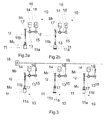
- FIG. 2a is a schematic diagram of a first embodiment of the device 10 according to the invention at the beginning of a first operating state and in particular a position of the compressor piston device 11 in a starting position of the expansion process of the container or a Komprimiervorgangs shown for compressing the pneumatic medium. It is assumed that an expansion of a preform, not shown here should be made. Also is in the 2a especially for reasons of clarity no blow mold for expanding the containers shown.
- a connected to the engine 15 circuit 18, which may in particular also have an intermediate circuit with a capacitor disposed therein (not shown here) provides the prime mover 15, which is preferably driven by electric drive motor 15, electrical energy to drive this engine 15 in To drive or operate the form of a drive motor and in particular an electric drive motor.
- the pump device 13 which is connected in operative connection with the drive machine 15 and in particular via a shaft 16 to the drive machine 15, is driven by the drive machine 15 and primarily by the rotor rotation of the drive machine 15 such that a hydraulic or liquid medium M located in at least one storage container 14 F is transported from the storage container 14 in the direction of a connecting line 17 for transporting the hydraulic medium M F and from there in the direction of an actuator device 12th
- the actuator device 12 driven by the volume flow of the hydraulic medium M F is in turn in operative connection with a compressor piston device 11, which has a compression chamber 11a and a piston element 11b, the piston element 11b at least partially protruding into the compression chamber 11a and moving within it can.
- the piston element 11b is moved in the direction of the bottom of the compression space 11a, so that the pneumatic or gaseous medium M G located inside the compression space 11a is compressed and in the direction a blow mold, not shown here escapes or is guided to cause expansion or inflation and deformation of the preform to a container.
- FIG. 2b is a schematic diagram of the already in 2a shown embodiment of the device 10 according to the invention, but now shown at the end of the first operating state and thus during or shortly before the start of a second operating state, in particular the end position of the compressor piston device 11 is shown after the expansion process of the container or after the Kompressiervorgang of the pneumatic medium. That is, after the expansion or inflation of the preform to a container and therefore after the expansion process is followed by a relaxation process in which the pneumatic medium used for expansion of the container, not as known from the general state of the art, is discharged to the outside environment ; but from the blow mold (not shown here) in the compression space 11a of the compressor piston device 11 is returned.
- the compression space 11a again fills with the pneumatic medium in such a way that the piston element 11b, which is now primarily at the lower end and thus at the bottom area of the compression space Is 11a, again upwards, that is pressed along the compression space 11a in a preferably vertical direction, so that by the movement of the piston member 11 b and a movement of the actuator device 12 is triggered.
- the piston element 11b and at least one component or component of the actuator device 12 are preferably coupled to one another in such a way that movement of the piston element 11b also moves the element or the constituent part of the actuator device 12 and especially an actuator piston element (not shown here) such that the hydraulic medium M F located in, for example, an actuator medium space (not shown here) is pressed out of the actuator medium space into the adjacent connecting lines 17 connected to the actuator medium space for transporting the hydraulic medium M F.
- the recirculating volume flow of the hydraulic medium M F then flows via the connecting line 17 to the pump device 13, which is consequently set in motion by the volume flow and thus preferably operates as a fluid motor.
- the prime mover 15, which is preferably coupled to the pump device 13 is driven by, for example, the rotational movement of the pump device 13 and the fluid motor and thus operates as an electric drive generator, which corresponding electric power to the adjacent electrical circuit 18 and in particular a DC link located therein with corresponding capacitor outputs.
- Figure 3 shows a schematic diagram of an arrangement of several of the in Fig.2a and Fig.2b shown first embodiments of the device 10 according to the invention, wherein the individual devices are arranged side by side and have a common circuit 18. Otherwise, the structure of the individual device substantially corresponds to the structure of the in the FIGS. 2a or 2b shown construction of the device 10th
- each device 10 is associated with its own blow mold (not shown here) so that each blow mold is independent of another but also on the same Transport device located blow mold can start a blowing process for expanding the container to be expanded.
- Figure 3 illustrates that the energy flows, ie the currents of the electrical energy generated by the drive machine 15 in the form of an electric drive generator of the juxtaposed in series devices 10 substantially compensate, wherein such in Figure 3 shown arrangement is primarily advantageous for rotary with a variety of blowing stations.
- electrical energy is not only taken from the intermediate circuit of the circuit 18, but also supplied to it by the devices 10 arranged in series and correspondingly also connected to the power grid 18 or circuit 18.
- the container treatment processes and in particular the process of expanding the preform into a container are coordinated with one another or delayed in time such that, for example, a first device 10 (left device of FIG. 3 ) receives electrical energy from the circuit 18 to begin an expansion process, a second device 10 (middle device of the FIG. 3 ) is already at the end of the expansion process itself and in particular is about to initiate the subsequent relaxation process, so that this second device neither needs to draw electrical energy from the circuit 18 nor supplies electrical energy to the circuit 18, while a third device 10 (right device of FIG. 3 ) is already relatively at the end of the relaxation process and substantially at the same time as the beginning of the expansion process of the first device has completed the expansion process and thus a feeding of electrical energy into the power grid 18 and the circuit 18.
- the circuit 18 is advantageously supplied to a comparatively large amount of energy, as this is also withdrawn again.
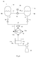
- FIG. 4 shown schematic diagram illustrates a second embodiment of the device 10 according to the invention, being comparable to the FIGS. 2a-3 also the device 10 of FIG. 4 an actuator device 12 and a standing in operative connection compressor piston device 11 has.
- two storage containers 14 are shown therein with hydraulic medium M F , wherein both storage containers 14 with at least one pump device 13 via corresponding connecting lines 17 in fluid communication stand.
- the pump device 13 is in turn connected to a drive machine 15, which operates either as a drive motor or as a drive generator, at least temporarily and at least partially mechanically connected via, for example, a shaft 16. With the help of the pump 13, a pressure difference between the two reservoirs 14 can be made.
- valve devices 19 are shown, which are arranged between the respective storage containers 14 and the actuator device 12 on a corresponding connecting line 17.
- the actuator device 12 has according to Figure 4 an actuator medium space 12a for receiving a hydraulic or liquid and flowable medium M F , and an actuator piston element 12b, which is moved primarily by the introduced into the Aktormediumraum 12a hydraulic medium M F within at least defined limits of movement on.
- the actuator device 12 is preferably mounted by means of at least one corresponding bearing device 30 within the device 10, preferably at a distance from the compressor piston device 11 and the storage containers 14, and the drive machine 15, the pump device 13 and the valve devices 19.
- the actuator device 12 or in particular the actuator piston element 12b is a component of the compressor piston device 11 and in particular of the piston element 11 b, so that by a displacement or movement of Aktorkolbenimplantations 12b directly and a movement of the piston member 11 b of the compressor piston device 11th and vice versa takes place without any connection element or signal transmission capable lines between the individual elements 11 b, 12 b must be arranged or switched.
- a blowing nozzle 21 is shown, which is preferably at least partially applied to the mouth region of the container to be expanded in order to prevent leakage of the pneumatic or gaseous medium M G during the expansion process, but also during the relaxation process and on the other introducing the pneumatic medium M G into the interior of the blow mold (not shown here) and thus into the interior of the container 20 to be expanded.
- this nozzle another connecting line 22 for transporting the pneumatic medium M G , which establishes a connection between the compressor piston device 11 and the container 20 to be expanded, which is preferably arranged within a blow mold, not shown here, so that the compressed pneumatic medium M G from the compression chamber 11 a the compressor piston device 11 of the blow mold and thus the preform or the container 20 can be transmitted.
- the procedure relating to the expansion process or the expansion process is substantially identical to those already in the above FIGS. 2a to 3 explained representations. Accordingly, during an expansion process, the drive machine 15 is activated and, in particular, its rotor (not shown here) is set in rotation so that the pump device 13 coupled to the drive machine 15 is activated and a hydraulic medium stored in the storage containers 14 is connected via connecting lines 17 through valve devices 19 transported through to the actuator device 12 and in particular in the Aktormediumraum 12a inside. It is noted, however, that the prime mover is in the in Fig. 4 embodiment shown can also operate independently of the expansion process or run.
- the expansion process may be at the in Fig. 4 shown embodiment can be started by opening a valve 19 and in particular that valve 19, which opens the reservoir with the higher pressure level.
- the other valve 19 preferably remains closed.
- the hydraulic medium M F propagating in the actuator medium chamber 12a and substantially continuously filling the space 12a thereby displaces the actuator piston element 12b within the actuator medium chamber 12a, whereby a piston element 11b, preferably connected to the actuator piston element 12b, is essentially in contact with the compressor piston device 11b is moved simultaneously with the Aktorkolbenelement 12b and moves into a compression space 11a in that the therein contained pneumatic or gaseous medium M G is compressed and in compressed or under pressure condition via at least one connecting line 22 the compression space 11 a in the direction leaves the container 20 to be expanded to inflate or expand.
- the expansion process ie after the container is substantially complete expanded or inflated, follows the relaxation process, during which the 20 located in the container pneumatic medium M G again moves out of the container 20, via the connecting line 22 in the direction of the compressor piston device 11 moves.
- This is made possible for example by the drive machine 15 no longer driving the pump device 13 due to deactivation of the drive machine 15, so that no further hydraulic medium M F from at least one of the indicated two storage containers 14 is introduced into the actuator device 12, whereby a defined pressure
- the prime mover continues to run.
- the above effect is achieved in that the valve 19 which is connected to the high pressure level Vorats memorier is closed. Subsequently, the valve 19 is opened with the connection to the pressure vessel with low pressure level.
- the piston element 11b is now forced out of the compression chamber 11a due to the pressure of the pneumatic medium M G flowing out of the container 20, so that the compression chamber 11a can again fill with the pneumatic medium M G.
- the actuator piston element 12b previously moved by the medium M F flowing in the actuator medium space 12a is again moved in the opposite direction, so that the hydraulic medium M F in the actuator medium space 12a again travels via at least one of the connecting lines 17 - is transported through at least one of the valve devices 19 - in at least one of the storage containers 14.
- a container treatment device such as a blowing device for blowing or expanding or expanding a preform is made possible to a container.
Landscapes
- Engineering & Computer Science (AREA)
- Manufacturing & Machinery (AREA)
- Mechanical Engineering (AREA)
- Blow-Moulding Or Thermoforming Of Plastics Or The Like (AREA)
Abstract
Description
- Die vorliegende Erfindung bezieht sich auf eine Vorrichtung und ein Verfahren zum Expandieren von Vorformlingen zu Behältnissen innerhalb einer Blasform mittels eines unter Druck befindlichen pneumatischen Mediums, gemäß den Oberbegriffen der Patentansprüche 1 und 7.
- Vorrichtungen und Verfahren zum Expandieren von Behältnissen finden beispielsweise in der Herstellungsindustrie von Getränkebehältnissen Anwendung, wobei mittels entsprechender Behandlungsanlagen unter anderem vornehmlich aus einem aus Kunststoff hergestellten Vorformling innerhalb einer Blasform ein entsprechend ebenfalls aus Kunststoff bestehendes Behältnis aufgeblasen bzw. expandiert wird.
- Dazu wird ein entsprechender Vorformling in einen Innenbereich einer meist zweiteilig ausgestalteten Blasform eingebracht, welche in deren Innenbereich zumindest eine Kavität aufweist, die für die Formgebung des späteren expandierten Behältnisses dient. Vornehmlich umschließt die Blasform den Vorformling vollumfänglich, zumindest um dessen unteren Bereich, wobei der Mündungsbereich des Vorformlings, welcher ein entsprechend angeformtes bzw. eingeschnittenes Innen- oder auch Außengewinde aufweist, zumindest teilweise aus der Blasform herausragen kann oder zumindest nicht innerhalb dem Bereich der Kavität der Blasform eingebracht ist, so dass eine Expansion und insbesondere eine Deformierung des Mündungsbereiches des Vorformlings während dessen Expansionsvorgangs vermieden wird.
- Mittels einer insbesondere auf einen Mündungsbereich des Vorformlings aufsetzbaren Blasdüse, durch welche ein unter Druck befindliches pneumatisches bzw. gasförmiges, fließfähiges Medium, wie ein Sterilisationsgas oder auch Luft in den Innenbereich der Blasform und demnach in den Innenbereich des zu expandierenden Behältnisses bzw. des zu expandierenden Vorforrmlings eingebracht wird, erfolgt ein Aufblasen bzw. ein Streckblasen des Vorformlings zu einem expandierten Behältnis.
- Bevorzugt wird dabei zusätzlich eine Reckstange von einem Einlass der Blasform, welcher sich vorzugsweise im Bereich des Mündungsbereiches des Vorformlings befindet, bis zu einem Bodenbereich der Blasform und dementsprechend des sich kontinuierlich expandierenden Behältnisses bewegt, wobei hierzu - je nach Positionierung bzw. Lagerung der Blasform - die Bewegung im Wesentlichen entlang einer Längsachse des Behältnisses und folglich im Wesentlichen in vertikale bzw. senkrechter Richtung zur Horizontalebene erfolgt.
- Es ist jedoch auch möglich, dass sich die Blasform (inklusive der Blasdüse) mit dem entsprechend zu expandierenden Vorformling in Richtung der Reckstange und/oder der Blasdüse bewegt, so dass durch die Bewegung der Blasform selbst, welche vergleichbar zur Bewegung der Reckstange im Wesentlichen in vertikaler bzw. senkrechter Richtung zur Horizontalebene erfolgt, demnach die Reckstande durch den Innenbereich des zu expandierenden Vorformlings bewegt wird, so dass die eingebrachte Druckluft im Wesentlichen gleichmäßig auf die Innenbereiche des Vorformlings aufgebracht werden kann, wodurch eine zur Expansion des Vorformlings erforderliche Deformierung des Wandungs- und Bodenbereiches verursacht wird.
- Es ist jedoch auch denkbar, dass sich sowohl die Reckstange und/oder die Blasdüse wie auch die Blasform selbst mit jeweils definierten Geschwindigkeiten während des Expansionsvorganges des Vorformlings aufeinander zu und/oder voneinander weg bewegen.
- Der Expansionsvorgang des Vorformlings zu einem Behältnis ist nur ein Behandlungsvorgang des Vorformlings oder auch des Behältnisses selbst von einer Vielzahl möglicher Behandlungsvorgänge. Demnach kann innerhalb einer gesamten Anlagen zum Behandeln von Behältnissen ein Vorformling mittels einem Vorwärmen, Erwärmen, Desinfizieren, Trocknen und/oder Expandieren bzw. Aufblasen bzw. Streckblasen behandelt werden, während ein expandiertes Behältnisses beispielsweise mit den Behandlungsschritten: Desinfizieren, Trocknen, Befüllen, Etikettieren, Verschließen mit Behältnisverschlüssen und/oder Verpacken behandelt werden kann.
- Die zur Expansion benötigten Blasformen sind vorzugsweise auf einem Transportelement, wie z.B. einem Transportrad oder Sternrad im Wesentlichen identisch zueinander beabstandet angeordnet und werden folglich durch die Drehung des Rades um dessen zentrale Drehachse auch entsprechend um diese Drehachse mit einer definierten Geschwindigkeit bewegt.
- Damit werden auch die Vorformlinge entlang eines vorgebbaren Transportpfades, der insbesondere senkrecht zu der Bewegungsrichtung der Blasdüse und/oder der Reckstange und/oder der Blasform steht, transportiert.
- Bevorzugt werden die zu expandierenden Vorformlinge bzw. Behältnisse mit zumindest einer weiteren Transporteinrichtung, nämlich einer Zuführtransporteinrichtung der Transporteinrichtung der Blasformen zugeführt, wobei diese Zuführtransporteinrichtung der zu expandierenden Vorformlinge beispielsweise ein Transportband oder ebenfalls ein Transportrad ist. Dementsprechend werden die expandierten Behältnisse vorzugsweise mittels zumindest einer entsprechenden Abführtransporteinrichtung von der Blasformtransporteinrichtung übernommen und beispielsweise einer nachfolgenden Bearbeitungsstation, wie z.B. einer Desinfektionsanlage oder einer Befüllanlage zum Befüllen des Behältnisses usw. zugeführt. In den Übergabebereichen der Zuführtransporteinrichtung und der Blasformtransporteinrichtung bzw. der Blasformtransporteinrichtung und der Abführtransporteinrichtung werden die zu expandierenden Behältnisse übergeben.
- Während des Expansionsvorganges des zu expandierenden Vorformlings innerhalb der Blasform werden hohe Blasdrücke von beispielsweise ca. 35 bis 40 bar eingesetzt, um insbesondere gewährleisten zu können, dass der Kunststoff des Vorformlings bzw. die Wandung des Vorformlings derart expandiert bzw. deformiert wird, dass dieser in alle definierten Bereiche der Kavität der Blasform eingebracht bzw. eingepresst wird, so dass ein in definierte Weise expandiertes Behältnis erzeugt werden kann. Der dazu erforderliche Blasdruck hängt dabei u.a. von der Zusammensetzung des Kunststoffes, der Erwärmung des Vorformlings, der Wandungsstärke des Vorformlings usw. ab.
- Die Erzeugung der zur Expansion des Vorformlings erforderlichen Blasluft bzw. Druckluft ist bekannterweise sehr energieaufwendig, insbesondere auch aufgrund der Abwärme, welche im Kompressor entsteht, der die Blasluft auf einen definierten Druck komprimiert. Die entstandene Abwärme wird bei Hochdruckkompressoren zumeist über einen entsprechend angeordneten Kühler an die Außenumgebung der Anlage abgeführt, um beispielsweise ein Überhitzen des Kompressors und damit eine Beschädigung dessen zu vermeiden.
- Demnach ist es die Aufgabe der vorliegenden Erfindung eine Vorrichtung und ein Verfahren zur Verfügung zu stellen, bei welchen die zum Komprimieren der Blasluft bzw. der Luft bzw. des pneumatischen Mediums aufgewendete Energie zu einem möglichst großen Anteil bei einem dem Expansionsvorgang nachfolgenden Entspannungsvorgang wieder zurückgewonnen werden kann.
- Diese Aufgabe löst die vorliegende Erfindung mittels einer Vorrichtung gemäß Anspruch 1 und einem Verfahren gemäß Anspruch 7. Vorteilhafte Ausführungsformen und Weiterbildungen sind Gegenstand der Unteransprüche.
- Die erfindungsgemäße Vorrichtung zum Expandieren von Vorformlingen zu Behältnissen innerhalb einer Blasform mittels eines unter Druck befindlichen pneumatischen Mediums weist insbesondere eine Verdichterkolbeneinrichtung zum Verdichten des pneumatischem Mediums auf, welche mit der Blasform in Strömungsverbindung steht, um einen Volumenstrom des pneumatischen Mediums in einen Innenbereich der Blasform einzubringen.
- Die Verdichterkolbeneinrichtung, welche hierbei vornehmlich einen Verdichtungsraum bzw. eine Druckkammer, innerhalb welcher das pneumatische Medium verdichtet wird, und mindestens ein Kolbenelement zum Verdichten des pneumatischen Mediums innerhalb des Verdichtungsraumes aufweist, ist vornehmlich direkt bzw. unmittelbar oder auch mittelbar über entsprechende Verbindungsleitungen zum Leiten der Druckluft mit der Blasform verbunden, um die komprimierte Blasluft bzw. das komprimierte pneumatische Medium vornehmlich ohne Kühlung in den Innenbereich der Blasform und damit in den Innenbereich des Vorformling einzupressen, so dass durch den direkten Übergang des komprimierten pneumatischen Mediums von der Verdichterkolbeneinrichtung zu der Blasform zumindest nur ein geringfügiger Anteil an Wärme an die Umgebung abgegeben wird, wodurch hierbei schon eine Energieeinsparung im Vergleich zu bekannten Blasverfahren erzielt wird.
- Damit ist bevorzugt die Verdichterkolbeneinrichtung direkt oder zumindest indirekt über entsprechende Verbindungsleitungen an den jeweiligen Blasstationen angeordnet und es sind bevorzugt eine Vielzahl von derartigen Verdichterkolbeneinrichtungen vorgesehen. Vorzugsweise ist pro Umformungs- bzw. Blasstation jeweils eine Verdichterkolbeneinrichtung vorgesehen.
- Des Weiteren weist die erfindungsgemäße Vorrichtung eine durch ein hydraulisches Medium aktivierbare Aktoreinrichtung auf, welche mit zumindest einem Element der Verdichterkolbeneinrichtung wechselwirkt, um während eines Expansionsvorganges des Behältnisses die Verdichterkolbeneinrichtung zur Verdichtung des pneumatischen Mediums anzutreiben und um während eines dem Expansionsvorgang zeitlich nachfolgenden Entspannungsvorgangs aufgrund des zurückfließenden Volumenstroms des pneumatischen Mediums in die Verdichterkolbeneinrichtung selbst angetrieben zu werden.
- Dabei kann die Aktoreinrichtung bevorzugt auch zumindest ein Abschnitt bzw. ein Bestandteil der Verdichterkolbeneinrichtung und insbesondere zumindest ein Bestandteil des Kolbenelementes der Verdichterkolbeneinrichtung sein. Es ist jedoch auch denkbar, dass die Aktoreinrichtung und die Verdichterkolbeneinrichtung zwei zueinander unterschiedliche Einrichtungen darstellen, welche derart beispielsweise mechanisch oder auch signalübertragungstechnisch miteinander verbunden sind, dass durch eine Bewegung der Aktoreinrichtung eine Bewegung der Verdichterkolbeneinrichtung und insbesondere des Kolbenelementes der Verdichterkolbeneinrichtung bzw. durch eine Bewegung der Verdichterkolbeneinrichtung und insbesondere des Kolbenelementes der Verdichterkolbeneinrichtung auch eine Bewegung der Aktoreinrichtung ermöglicht wird.
- Das pneumatische Medium ist bevorzugt ein gasförmiges Medium, wie Druckluft oder ein komprimierbares Gas, wie ein Sterilisationsgas oder ähnliches.
- Die Aktoreinrichtung selbst weist vornehmlich ein Aktorkolbenelement und einen Aktormediumraum auf, innerhalb welchem vornehmlich ein hydraulisches Medium eingebracht wird, um das Aktorkolbenelement zu bewegen. Durch die Bewegung des Aktorkolbenelementes wird vornehmlich auch das mit diesem Aktorkolbenelement in Wirkverbindung stehende Kolbenelement der Verdichterkolbeneinrichtung bewegt, so dass während eines Expansionsvorganges des zu expandierenden Behältnisses das Kolbenelement der Verdichterkolbeneinrichtung ein in dem Verdichtungsraum befindliches pneumatisches Medium komprimiert, welches dann vornehmlich an ein Blasdüse (einer Blasform) bzw. eine Blasform übertragen wird.
- Es ist jedoch auch denkbar, dass die Aktoreinrichtung oder zumindest ein Bestandteil der Aktoreinrichtung ein elektronisches Signal von beispielsweise einer Steuerungseinrichtung empfängt und in entsprechende mechanische Bewegungen umsetzt, um dadurch die Verdichterkolbeneinrichtung anzusteuern bzw. anzutreiben.
- In einer bevorzugten Ausführungsform ist zumindest ein ein hydraulisches Medium aufweisendes Vorratsbehältnis über wenigstens eine Verbindungsleitung mit der Aktoreinrichtung verbunden, um der Aktoreinrichtung zumindest zeitweise und zumindest teilweise das hydraulische Medium zur Verfügung zu stellen.
- Das hydraulische Medium ist dabei vorzugsweise ein flüssiges und insbesondere fließfähiges Medium, wie Wasser, eine wässrige Lösung oder ein Schmiermittel, wie Öl oder ähnliches.
- Es ist auch denkbar, dass die Vorrichtung insgesamt zwei oder mehr Vorratsbehältnisse aufweist, um das hydraulische Medium zu speichern und über die Verbindungsleitungen zum Transportieren des hydraulischen Mediums an die Aktoreinrichtung zu übergeben. Hierbei wird vorzugsweise immer nur eines der Vorratsbehältnisse über entsprechende Ventile geöffnet, um der Aktoreinrichtung das hydraulische Medium zur Verfügung stellen zu können.
- In einer weiteren bevorzugten Ausführungsform steht zumindest eine Pumpeneinrichtung mit dem Vorratsbehältnis in Wirkverbindung, um zumindest zeitweise einen Transport des hydraulischen Mediums aus dem Vorratsbehältnis zu der Aktoreinrichtung zu bewirken.
- In diesem Falle ist beispielsweise zumindest eine Antriebsmaschine mit der Pumpeneinrichtung wirkverbunden, um die Pumpeneinrichtung anzutreiben und/oder von einer aktivierten Pumpeneinrichtung angetrieben oder zumindest entlastet zu werden.
- Demzufolge ist die Antriebsmaschine, welche vorzugsweise wechselweise als ein elektrischer Antriebsmotor und als ein elektrischer Antriebsgenerator wirkt, bevorzugt über eine Welle im Wesentlichen unmittelbar und/oder über Kupplungseinrichtungen, wie z.B. ineinander greifenden Zahnrädern, welche an entsprechende Wellen der Antriebsmaschine und der Pumpeneinrichtung angeordnet sind, im Wesentlichen mittelbar mit der Pumpeneinrichtung wirkverbunden, so dass eine Drehbewegung des Rotors der Antriebseinrichtung eine Drehbewegung des Rotors der Pumpeneinrichtung bewirkt, um ein Pumpen des hydraulischen Mediums aus einem der Vorratsbehältnisse durch die Verbindungsleitungen in Richtung der Aktoreinrichtung zu bewirken.
- In einer weiteren bevorzugten Ausführungsform ist eine Steuerungseinrichtung mit der Antriebsmaschine und/oder zumindest einer zwischen dem Vorratsbehältnis und der Aktoreinrichtung angeordneten Ventileinrichtung signalübertragungstechnisch verbunden, um die Antriebsmaschine und/oder die Ventileinrichtung zumindest zeitweise bedarfsgerecht anzusteuern. Bevorzugt handelt es sich bei dieser Steuerungseinrichtung um eine Regelungseinrichtung, d.h. es ist vorteilhaft ein Regelkreis vorhanden.
- Demnach ist es denkbar. dass eine Ventileinrichtung im Wesentlichen zeitgleich mit einer Antriebsmaschine aktiviert wird, um einen Durchfluss eines Volumenstroms aus hydraulischem Medium aus dem zumindest einen Vorrastbehältnis in Richtung der Aktoreinrichtung zu ermöglichen, sofern die Antriebsmaschine als Antriebsmotor wirkt und die Pumpeneinrichtung ansteuert. Demzufolge kann die Ventileinrichtung geschlossen werden, wenn weder ein Expansionsvorgang noch ein Entspannungsvorgang stattfindet, d.h., insbesondere, wenn keine Behandlung eines Behältnisses erfolgt. Die Ventileinrichtung ist auch während des Entspannungsvorgangs geöffnet, d.h. nachdem das Behältnis expandiert wurde und die in die Blasform eingepresste Druckluft wieder aus dieser entweicht. Dabei wird das aus der Blasform entweichende pneumatische Medium zurück an die Verdichterkolbeneinrichtung und insbesondere in den Verdichtungsraum der Verdichterkolbeneinrichtung geführt, in welchem sich das pneumatische Medium ausbreitet und folglich das Kolbenelement aus dem Verdichtungsraum heraus bewegt. Vornehmlich ist das Kolbenelement mit keiner mechanischen Kraft beaufschlagt und kann demnach im Wesentlichen ungestört von dem sich im Verdichtungsraum ausbreitenden zurückfließenden pneumatischen Medium bewegt werden.
- Durch die Bewegung des Kolbenelementes wird vorzugsweise auch die Aktoreinrichtung aktiviert und insbesondere das Aktorkolbenelement derart bewegt, dass sich ein in dem Aktormediumraum befindliches hydraulisches Medium aus diesem Raum heraus bewegt, und über die Verbindungleitungen und die geöffneten Ventileinrichtungen in Richtung des Vorrastbehältnisses, aus welchem das hydraulische Medium während des Expansionsvorganges entnommen wurde, transportiert wird. Dabei durchfließt das hydraulische Medium auch derart die Pumpeneinrichtung, dass diese durch den Volumenstrom des zurückfließenden hydraulischen Mediums angeregt bzw. aktiviert wird, wobei folglich auch eine mit der Pumpeneinrichtung in Wirkverbindung stehende Antriebsmaschine, die nun als Antriebsgenerator wirkt, angetrieben wird.
- Des Weiteren wird folglich auch ein Verfahren zum Expandieren von Vorformlingen zu Behältnissen innerhalb einer Blasform mittels eines unter Druck befindlichen pneumatischen Mediums beansprucht, gemäß welchem während eines Expansionsvorganges zum Expandieren des Behältnisses eine Verdichterkolbeneinrichtung zum Verdichten des pneumatischen Mediums durch eine mit einem hydraulischen Medium betriebene und mit zumindest einem Element der Verdichterkolbeneinrichtung wechselwirkende Aktoreinrichtung angesteuert wird, um das pneumatische Medium in einen Innenbereich der Blasform zu transportieren und bei welchem während eines dem Expansionsvorgang nachfolgenden Entspannungsvorgangs das pneumatische Medium in die Verdichterkolbeneinrichtung zurückgeführt wird, wodurch die Aktoreinrichtung zu einer Rückführung des hydraulischen Mediums veranlasst wird.
- In einer bevorzugten Ausführungsform wird dabei vornehmlich während des Entspannungsvorgangs das hydraulische bzw. flüssige und bevorzugt fließfähige Medium, welches beispielsweise ein Sterilisationsmedium, Wasser, eine wässrige Lösung oder ein Öl ist, über wenigstens eine Verbindungsleitung einer Pumpeneinrichtung zugeführt, welche in Wirkverbindung mit einer Antriebsmaschine steht, so dass durch einen Antrieb der Pumpeneinrichtung mittels dem Volumenstrom des zurückfließenden hydraulischen Mediums auch die antriebsmaschine in Form eines Antriebsgenerators betrieben wird.
- Das heißt, dass demnach vorzugsweise die durch einen Volumenstrom des durchfließenden hydraulischen Mediums aktivierte Pumpeneinrichtung die Antriebmaschine als Antriebsgenerator zur Erzeugung von elektrischer Energie antreibt und/oder das Fluid in einen unter Druck stehenden Behälter fördert.
- Demzufolge ist die Antriebsmaschine, welche vornehmlich eine elektrische Antriebsmaschine ist, die als Antriebsmotor oder auch als Antriebsgenerator fungieren kann, vorzugsweise mit einem elektrischen Stromkreis und insbesondere mit einem elektrischen Zwischenkreis, welcher vorzugsweise zumindest einen Kondensator oder ein vergleichbares Speicherelement zum Speichern elektrischer Energie aufweist, verbunden. Folglich wird die durch die Antriebsmaschine erzeugte elektrische Energie während eines Entspannungsvorganges in den elektrischen Stromkreis und vornehmlich in den Zwischenkreis des elektrischen Stromkreises eingespeist, wodurch beispielsweise der Kondensator aufgeladen werden kann. Diese eingespeiste elektrische Energie steht zumindest teilweise und zumindest zeitweise während eines Expansionsvorganges beispielsweise eines weiteren zu expandierenden Vorformlings der elektrischen Antriebsmaschine wieder zur Verfügung, um diese in Form eines Antriebsmotors wiederrum derart anzutreiben bzw. zu aktivieren, dass der Rotor der Antriebsmaschine den Rotor der Pumpeneinrichtung antreibt, um eine Entnahme des hydraulischen Mediums aus einem Vorratsbehältnis sowie das Leiten des hydraulischen Mediums von dem Vorratsbehältnis zu der Aktoreinrichtung zu bewirken.
- In einer weiteren bevorzugten Ausführungsform weisen die einzelnen erfindungsgemäßen Vorrichtungen einen gemeinsamen Stromkreis auf, so dass sich die Energieströme, d.h. die Ströme der von der Antriebsmaschine in Form eines elektrischen Antriebsgenerators erzeugte elektrische Energie der vorzugsweise nebeneinander in Reihe angeordneten erfindungsgemäßen Vorrichtungen im Wesentlichen ausgleichen, wobei eine derartige Anordnung vornehmlich für Rundläufer mit einer Vielzahl von Blasstationen und demnach einer Vielzahl von erfindungsgemäßen Vorrichtungen, wobei bevorzugt jeder Blasstation eine eigene erfindungsgemäße Vorrichtung zugeordnet ist, vorteilhaft ist.
- Demzufolge wird durch die in Reihe angeordneten und entsprechend auch mit dem Stromnetz bzw. Stromkreis verschaltenen erfindungsgemäßen Vorrichtungen im Wesentlichen kontinuierlich auch elektrische Energie, nicht nur aus dem Zwischenkreis des Stromkreises entnommen, sondern diesem auch zugeführt. Dabei sind die Behältnisbehandlungsvorgänge und insbesondere der Vorgang des Expandierens des Vorformlings zu einem Behältnis derart miteinander bzw. aufeinander abgestimmt bzw. zeitverzögert, dass während beispielsweise eine erste erfindungsgemäße Vorrichtung elektrische Energie aus dem Stromkreis bezieht, um beispielsweise einen Expansionsvorgang zu beginnen, eine zweite erfindungsgemäße Vorrichtung beispielsweise bereits am Ende des Expansionsvorganges selbst ist bzw. insbesondere kurz vor Einleitung des nachfolgenden Entspannungsvorganges steht, so dass diese zweite erfindungsgemäße Vorrichtung weder elektrische Energie aus dem Stromkreis beziehen muss, noch elektrische Energie dem Stromkreis zuführt, während beispielsweise eine dritte erfindungsgemäße Vorrichtung 10 sich bereits relativ am Ende des Entspannungsvorganges befindet und im Wesentlichen zeitgleich mit dem Beginn des Expansionsvorganges der ersten Vorrichtung den Entspannungsvorgang und damit ein Einspeisen von elektrischer Energie in das Stromnetz bzw. den Stromkreis abgeschlossen hat.
- Dank der Einspeisung von elektrischer Energie, erzeugt durch einen Antriebsgenerator, welcher zumindest mittelbar über den zurückfließenden Volumenstrom des hydraulischen Mediums angetrieben wird, erfolgt eine Energierückgewinnung, so dass zumindest ein Großteil der während des Expansionsvorganges benötigten elektrischen Energie wieder in den Zwischenkreis eingespeist werden kann.
- Bei einer weiteren vorteilhaften Ausführungsform weist die Vorrichtung ein elektrisches Speichermittel, insbesondere zum Speichern von von der Antriebsmaschine erzeugter elektrischer Energie auf. Bei diesem Speichermittel kann es sich beispielsweise um ein Batterie oder einen Kondensator handeln. Dieses Speichermittel kann dabei in einen Zwischenkreis integriert sein.
- In einer weiteren bevorzugten Ausführungsform steuert zumindest eine Steuerungseinrichtung die Antriebsmaschine und/oder zumindest eine zwischen zumindest einem Vorratsbehältnis zum Speichern des hydraulischen Mediums und der Aktoreinrichtung angeordnete Ventileinrichtung an, um während des Expansionsvorganges ein Abführen des hydraulischen Mediums aus dem Vorratsbehältnis zu der Aktoreinrichtung und während des Entspannungsvorgangs von der Aktoreinrichtung zu dem Vorratsbehältnis zu ermöglichen.
- Demzufolge ist die Steuerungseinrichtung, welche beispielsweise kabellos oder über entsprechende Verbindungskabel mit der Antriebsmaschine und/oder der Ventileinrichtung verbunden sein kann, derart signalübertragungstechnisch mit der Antriebsmaschine und vorzugsweise auch mit der Ventileinrichtung verbunden, dass während eines Expansionsvorganges vornehmlich die Antriebsmaschine als Antriebsmotor von der Steuerung aktiviert wird, während die Ventileinrichtung geöffnet ist, so dass ein Durchfließen des hydraulischen Mediums aus dem Vorratsbehältnis in Richtung der Aktoreinrichtung erfolgen kann. Auch während des Entspannungsvorgangs ist die Ventileinrichtung vornehmlich geöffnet, während die Antriebsmaschine vorzugsweise aufgrund der Signalübertragung zwischen der Steuerungseinrichtung und der Antriebsmaschine als Antriebsgenerator arbeitet, so dass ein Volumenstrom des rückfließenden hydraulischen Mediums die Pumpeneinrichtung und dadurch auch die mit der Pumpeneinrichtung in Wirkverbindung - bevorzugt über eine Welle - stehende Antriebsmaschine antreiben kann, so dass durch die Antriebsmaschine bzw. den Antriebsgenerator elektrische Energie erzeugt wird.
- Es wird darauf hingewiesen, dass die vorliegende Erfindung nicht nur bei Blasformmaschinen anwendbar ist, sondern allgemein bei Anwendungen, bei denen Druckluft erzeugt wird und diese insbesondere auch wieder zeitweise aus einem mit der Druckluft beaufschlagten Raum (oder einem anderen Raum) ausströmt.
- Die Erfindung betrifft daher auch allgemein eine Vorrichtung zum Erzeugen eines unter Druck befindlichen pneumatischen Mediums, wobei eine Verdichterkolbeneinrichtung zum Verdichten des pneumatischem Mediums mit einem mit dem gasförmigen Medium zu beaufschlagenden Raum in Strömungsverbindung steht, um einen Volumenstrom des pneumatischen Mediums in einen Innenbereich dieses Raums einzubringen, und eine durch ein hydraulisches Medium aktivierbare Aktoreinrichtung mit zumindest einem Element der Verdichterkolbeneinrichtung wechselwirkt, um während der Beaufschlagung dieses Raums die Verdichterkolbeneinrichtung zur Verdichtung des pneumatischen Mediums anzutreiben und um während eines dem Expansionsvorgang zeitlich nachfolgenden Entspannungsvorgangs des Raums aufgrund des zurückfließenden Volumenstroms des pneumatischen Mediums in die Verdichterkolbeneinrichtung selbst angetrieben zu werden.
- Weitere Vorteile, Ziele und Eigenschaften der vorliegenden Erfindung werden anhand nachfolgender Beschreibung anliegender Zeichnung erläutert, in welcher beispielhaft unter anderem Ausführungsformen der erfindungsgemäßen Vorrichtung und deren Wirkungsweise dargestellt wird.
- Komponenten, welche in den Figuren wenigstens im Wesentlichen hinsichtlich ihrer Funktion übereinstimmen, können hierbei mit gleichen Bezugszeichen gekennzeichnet sein, wobei diese Komponenten nicht in allen Figuren gekennzeichnet und erläutert sein müssen.
- In den Figuren zeigen:
- Fig.1
- eine Prinzipskizze einer Ausführungsform einer Blasform zum Expandieren von Vorformlingen zu Behältnissen;
- Fig.2a
- eine Prinzipskizze einer ersten Ausführungsform der erfindungsgemäßen Vorrichtung zu Beginn eines ersten Betriebszustandes;
- Fig.2b
- eine Prinzipskizze der in
Fig.2a gezeigten Ausführungsform der erfindungsgemäßen Vorrichtung am Ende des ersten Betriebszustandes; - Fig.3
- eine Prinzipskizze einer Anordnung mehrerer der in
Fig.2a und Fig.2b gezeigten ersten Ausführungsformen der erfindungsgemäßen Vorrichtung; und - Fig.4
- eine Prinzipskizze einer zweiten Ausführungsform der erfindungsgemäßen Vorrichtung.
-
Fig.1 zeigt eine Prinzipskizze einer Ausführungsform einer Blasform 1 zum Expandieren von Vorformlingen (hier nicht gezeigt) zu Behältnissen (hier nicht gezeigt). Die Blasform 1 weist dazu beispielsweise zwei Blasformhälften 1a, 1 b auf, die wiederum jeweils eine Kavität 2a bzw. 2b aufweisen, innerhalb welcher das zu expandierende Behältnis bzw. der Vorformling zumindest zeitweise und zumindest teilweise aufgenommen wird. Zumindest während des Expansionsvorganges sind die beiden Blasformhälften 1 a und 1 b derart miteinander verschlossen, dass vorzugsweise lediglich über einen oberen Bereich 3 der Blasform 1, welcher den Mündungsbereich des hier nicht gezeigten Vorformlings umschließt, eine Druckluft in das Innere der Blasform 1 und insbesondere in den in den Kavitäten 2a, 2b eingebrachten Vorformling eingepresst werden kann. - In der
Fig.2a ist eine Prinzipskizze einer ersten Ausführungsform der erfindungsgemäßen Vorrichtung 10 zu Beginn eines ersten Betriebszustandes und insbesondere eine Stellung der Verdichterkolbeneinrichtung 11 in einer Anfangs- bzw. Startstellung des Expansionsvorgangs des Behältnisses bzw. eines Komprimiervorgangs zum Komprimieren des pneumatischen Mediums gezeigt. Es wird davon ausgegangen, dass eine Expansion eines hier nicht gezeigten Vorformlings erfolgen soll. Auch ist in derFig.2a insbesondere aus Gründen der Übersichtlichkeit keine Blasform zum Expandieren der Behältnisse gezeigt. - Ein mit der Antriebsmaschine 15 verbundener Stromkreis 18, welcher insbesondere auch einen Zwischenkreis mit einem darin angeordneten Kondensator aufweisen kann (hier nicht gezeigt) liefert der Antriebsmaschine 15, welche vorzugsweise eine mit elektrischer Energie antreibbare Antriebsmaschine 15 ist, elektrische Energie, um diese Antriebsmaschine 15 in Form eines Antriebsmotors und insbesondere eines elektrischen Antriebsmotors anzutreiben bzw. zu betreiben.
- Die mit der Antriebsmaschine 15 in Wirkverbindung und insbesondere über eine Welle 16 mit der Antriebsmaschine 15 verbundene Pumpeneinrichtung 13 wird durch die Antriebsmaschine 15 und vornehmlich durch die Rotordrehung der Antriebsmaschine 15 derart angetrieben, dass ein in zumindest einem Vorratsbehältnis 14 befindliches hydraulisches bzw. flüssiges Medium MF aus dem Vorratsbehältnis 14 in Richtung einer Verbindungsleitung 17 zum Transportieren des hydraulischen Mediums MF transportiert wird und von dort aus in Richtung einer Aktoreinrichtung 12.
- Die durch den Volumenstrom des hydraulischen Mediums MF angetriebene Aktoreinrichtung 12 befindet sich wiederum in Wirkverbindung mit einer Verdichterkolbeneinrichtung 11, welche einen Verdichtungsraum 11 a sowie ein Kolbenelement 11b aufweist, wobei das Kolbenelement 11 b zumindest teilweise in den Verdichtungsraum 11a hineinragt und innerhalb dessen bewegt werden kann.
- Durch die vornehmliche mechanische Bewegung zumindest eines Elementes bzw. eines Bestandteils der Aktoreinrichtung 12 wird insbesondere das Kolbenelement 11b in Richtung des Bodens des Verdichtungsraumes 11a bewegt, so dass das sich innerhalb des Verdichtungsraumes 11a befindliche pneumatische bzw. gasförmige Medium MG komprimiert wird und in Richtung einer hier nicht gezeigten Blasform entweicht bzw. geführt wird, um eine Expansion bzw. ein Aufblasen und Deformieren des Vorformlings zu einem Behältnis zu bewirken.
- In der
Fig.2b ist eine Prinzipskizze der bereits inFig.2a gezeigten Ausführungsform der erfindungsgemäßen Vorrichtung 10, jedoch nun am Ende des ersten Betriebszustandes und damit während oder zeitlich kurz vor Beginn eines zweiten Betriebszustandes gezeigt, wobei insbesondere die Endstellung der Verdichterkolbeneinrichtung 11 nach dem Expansionsvorgang des Behältnisses bzw. nach dem Komprimiervorgang des pneumatischen Mediums gezeigt ist. D.h., dass nach dem Expandieren bzw. Aufblasen des Vorformlings zu einem Behältnis und demzufolge nach dem Expansionsvorgang sich ein Entspannungsvorgang anschließt, bei welchen das zur Expansion des Behältnisses verwendete pneumatische Medium, nicht wie aus dem allgemeinen Stand der Technik bekannt, an die Außenumgebung abgegeben wird; sondern aus der Blasform (hier nicht gezeigt) in den Verdichtungsraum 11a der Verdichterkolbeneinrichtung 11 zurückgeführt wird. D.h., dass sich der Verdichtungsraum 11a wieder derart mit dem pneumatischen Medium füllt, dass das Kolbenelement 11 b, welches sich vornehmlich nun an unteren Ende und damit am Bodenbereich des Verdichtungsraumes 11a befindet, wieder nach oben, d.h. entlang des Verdichtungsraumes 11a in vorzugsweise vertikaler Richtung gedrückt wird, so dass durch die Bewegung des Kolbenelementes 11 b auch eine Bewegung der Aktoreinrichtung 12 ausgelöst wird. - Vorzugsweise sind das Kolbenelement 11 b und zumindest ein Bestandteil oder Bauteil der Aktoreinrichtung 12 derart miteinander gekoppelt, dass durch eine Bewegung des Kolbenelementes 11b auch das Element bzw. der Bestandteil der Aktoreinrichtung 12 und vornehmlich ein Aktorkolbenelement (hier nicht gezeigt) derart bewegt wird, dass das sich in beispielsweise einem Aktormediumraum (hier nicht gezeigt) befindliche hydraulische Medium MF durch die Bewegung des Aktorkolbenelementes aus dem Aktormediumraum hinaus in die angrenzenden und mit dem Aktormediumraum verbundenen Verbindungsleitungen 17 zum Transportieren des hydraulischen Mediums MF gedrückt wird.
- Der zurückfließende Volumenstrom des hydraulischen Mediums MF fließt dann über die Verbindungsleitung 17 zur Pumpeneinrichtung 13, welche folglich von dem Volumenstrom in Bewegung versetzt wird und demnach vorzugsweise als Fluidmotor arbeitet. Daraufhin wird auch die Antriebsmaschine 15, welche vorzugsweise mit der Pumpeneinrichtung 13 gekoppelt ist durch beispielsweise die Rotationsbewegung der Pumpeneinrichtung 13 bzw. des Fluidmotors angetrieben und arbeitet folglich als elektrischer Antriebsgenerator, welcher entsprechende elektrische Leistung an den angrenzenden elektrischen Stromkreis 18 und insbesondere einen darin befindlichen Zwischenkreis mit entsprechendem Kondensator abgibt.
- Anstatt des Kondensators kann jedoch auch beispielsweise ein Akkumulator angeordnet sein, welcher durch die entsprechend von dem Antriebsgenerator erzeugte elektrische Energie aufgeladen wird.
-
Fig.3 zeigt eine Prinzipskizze einer Anordnung mehrerer der inFig.2a und Fig.2b gezeigten ersten Ausführungsformen der erfindungsgemäßen Vorrichtung 10, wobei die einzelnen Vorrichtungen nebeneinander angeordnet sind und einen gemeinsamen Stromkreis 18 aufweisen. Ansonsten entspricht der Aufbau der einzelnen Vorrichtung im Wesentlichen dem Aufbau des in denFiguren 2a bzw. 2b gezeigten Aufbaus der Vorrichtung 10. - Vorzugsweise ist jede Vorrichtung 10 einer eigenen Blasform (hier nicht gezeigt) zugeordnet, so dass jede Blasform unabhängig zu einer anderen sich jedoch ebenfalls auf der gleichen Transporteinrichtung befindlichen Blasform einen Blasvorgang zum Expandieren des zu expandierenden Behältnisses beginnen kann.
-
Fig.3 verdeutlicht, dass sich die Energieströme, d.h. die Ströme der von der Antriebsmaschine 15 in Form eines elektrischen Antriebsgenerators erzeugte elektrische Energie der nebeneinander in Reihe angeordneten Vorrichtungen 10 im Wesentlichen ausgleichen, wobei eine derartig inFig.3 aufgezeigte Anordnung vornehmlich für Rundläufer mit einer Vielzahl von Blasstationen vorteilhaft ist. - Demzufolge wird durch die in Reihe angeordneten und entsprechend auch mit dem Stromnetz 18 bzw. Stromkreis 18 verschaltenen Vorrichtungen 10 im Wesentlichen kontinuierlich auch elektrische Energie, nicht nur aus dem Zwischenkreis des Stromkreises 18 entnommen, sondern diesem auch zugeführt. Dabei sind die Behältnisbehandlungsvorgänge und insbesondere der Vorgang des Expandierens des Vorformlings zu einem Behältnis derart miteinander bzw. aufeinander abgestimmt bzw. zeitverzögert, dass während beispielsweise eine erste Vorrichtung 10 (linke Vorrichtung der
Figur 3 ) elektrische Energie aus dem Stromkreis 18 bezieht, um einen Expansionsvorgang zu beginnen, eine zweite Vorrichtung 10 (mittlere Vorrichtung derFigur 3 ) bereits am Ende des Expansionsvorganges selbst ist und insbesondere kurz vor Einleitung des nachfolgenden Entspannungsvorganges steht, so dass diese zweite Vorrichtung weder elektrische Energie aus dem Stromkreis 18 beziehen muss, noch elektrische Energie dem Stromkreis 18 zuführt, während eine dritte Vorrichtung 10 (rechte Vorrichtung derFigur 3 ) sich bereits relativ am Ende des Entspannungsvorganges befindet und im Wesentlichen zeitgleich mit dem Beginn des Expansionsvorganges der ersten Vorrichtung den Entspannungsvorgang und damit ein Einspeisen von elektrischer Energie in das Stromnetz 18 bzw. den Stromkreis 18 abgeschlossen hat. - Demzufolge wird vorteilhaft dem Stromkreis 18 im Wesentlichen eine vergleichbar große Menge an Energie zugeführt, wie diesem auch wieder entzogen wird.
- Die in der
Fig.4 gezeigte Prinzipskizze verdeutlicht eine zweite Ausführungsform der erfindungsgemäßen Vorrichtung 10, wobei vergleichbar zu denFiguren 2a - 3 auch die Vorrichtung 10 derFigur 4 eine Aktoreinrichtung 12 sowie eine damit in Wirkverbindung stehende Verdichterkolbeneinrichtung 11 aufweist. Zudem sind zwei Vorratsbehältnisse 14 mit darin befindlichem hydraulischem Medium MF gezeigt, wobei beide Vorratsbehältnisse 14 mit zumindest einer Pumpeneinrichtung 13 über entsprechende Verbindungsleitungen 17 in Fluidverbindung stehen. Die Pumpeneinrichtung 13 ist wiederum mit einer Antriebsmaschine 15, welche entweder als Antriebsmotor oder als Antriebsgenerator arbeitet, zumindest zeitweise und zumindest teilweise mechanisch über beispielsweise eine Welle 16 miteinander verbunden. Mit Hilfe der Pumpe 13 kann zwischen den beiden Vorratsbehältern 14 ein Druckunterschied hergestellt werden. - Des Weiteren sind in der
Fig.4 zwei Ventileinrichtungen 19 gezeigt, welche zwischen den jeweiligen Vorratsbehältnissen 14 und der Aktoreinrichtung 12 an einer entsprechenden Verbindungsleitung 17 angeordnet sind. - Die Aktoreinrichtung 12 weist gemäß
Fig.4 einen Aktormediumraum 12a zur Aufnahme eines hydraulischen bzw. flüssigen und fließfähigen Mediums MF, sowie ein Aktorkolbenelement 12b, welches vornehmlich durch das in den Aktormediumraum 12a eingebrachte hydraulische Medium MF innerhalb zumindest definierter Bewegungsgrenzen bewegt wird, auf. - Die Aktoreinrichtung 12 ist vorzugsweise mittels zumindest einer entsprechenden Lagerungseinrichtung 30 innerhalb der Vorrichtung 10 bevorzugt beabstandet von der Verdichterkolbeneinrichtung 11 und den Vorratsbehältnissen 14, sowie der Antriebsmaschine 15, der Pumpeneinrichtung 13 und den Ventileinrichtungen 19 gelagert.
- Es ist jedoch auch denkbar, dass die Aktoreinrichtung 12 oder insbesondere das Aktorkolbenelement 12b ein Bestandteil der Verdichterkolbeneinrichtung 11 und insbesondere des Kolbenelementes 11 b ist, so dass durch eine Verdrängung bzw. Bewegung des Aktorkolbenelementes 12b direkt auch eine Bewegung des Kolbenelementes 11 b der Verdichterkolbeneinrichtung 11 und andersherum stattfindet, ohne dass etwaige Verbindungelement oder signalübertragungsfähige Leitungen zwischen den einzelnen Elementen 11 b, 12b angeordnet bzw. geschalten sein müssen.
- Des Weiteren ist eine Blasdüse 21 aufgezeigt, welches vorzugsweise zumindest teilweise derart auf dem Mündungsbereich des zu expandierenden Behältnisses aufgebracht wird, um zum einen ein Entweichen des pneumatischen bzw. gasförmigen Mediums MG während des Expansionsvorganges, jedoch auch während des Entspannungsvorganges zu verhindern und zum anderen ein Einbringen des pneumatischen Mediums MG in den Innenbereich der Blasform (hier nicht gezeigt) und damit in den Innenbereich des zu expandierenden Behältnisses 20 zu ermöglichen. Zumindest abschnittsweise erstreckt sich in diese Blasdüse eine weitere Verbindungsleitung 22 zum Transportieren des pneumatischen Mediums MG, welche eine Verbindung zwischen der Verdichterkolbeneinrichtung 11 und dem zu expandierenden Behältnis 20, welches bevorzugter Weise innerhalb einer hier nicht gezeigten Blasform angeordnet ist, herstellt, damit das komprimierte pneumatische Medium MG aus dem Verdichtungsraum 11a der Verdichterkolbeneinrichtung 11 der Blasform und damit dem Vorformling bzw. dem Behältnis 20 übertragen werden kann.
- Die Vorgehensweise bezüglich des Expansionsvorganges beziehungsweise des Entspannungsvorganges ist im Wesentlichen identisch zu den bereits oben in den
Figuren 2a bis 3 erläuterten Darstellungen. Demnach wird während eines Expansionsvorganges die antriebsmaschine 15 aktiviert und insbesondere beispielsweise deren Rotor (hier nicht gezeigt) in Rotation versetzt, so dass auch die mit der Antriebsmaschine 15 gekoppelte Pumpeneinrichtung 13 aktiviert wird und ein in den Vorratsbehältnissen 14 gelagertes hydraulisches Medium über Verbindungsleitungen 17 durch Ventileinrichtungen 19 hindurch zu der Aktoreinrichtung 12 und insbesondere in den Aktormediumraum 12a hinein transportiert. Es wird jedoch darauf hingewiesen, dass die Antriebsmaschine bei der inFig. 4 gezeigten Ausführungsform auch unabhängig von dem Expansionsvorgang arbeiten bzw. laufen kann. - Der Expansionsvorgang kann bei der in
Fig. 4 gezeigten Ausführungsform durch ein Öffnen eines Ventils 19 gestartet werden und insbesondere desjenigen Ventils 19, welches den Vorratsbehälter mit dem höheren Druckniveau öffnet. Das andere Ventil 19 bleibt bevorzugt geschlossen. - Das sich im Aktormediumraum 12a ausbreitende und den Raum 12a im Wesentlichen kontinuierlich ausfüllende hydraulische Medium MF verschiebt dadurch folglich das Aktorkolbenelement 12b innerhalb des Aktormediumraumes 12a, wodurch ein vorzugsweise mit dem Aktorkolbenelement 12b verbundenes bzw. in Wirkverbindung stehendes Kolbenelement 11 b der Verdichterkolbeneinrichtung 11 im Wesentlichen zeitgleich mit dem Aktorkolbenelement 12b bewegt wird und sich derart in einen Verdichtungsraum 11a hinein bewegt, dass das darin befindliche pneumatische bzw. gasförmige Medium MG komprimiert wird und in komprimiertem bzw. unter Druck befindlichem Zustand über zumindest eine Verbindungsleitung 22 den Verdichtungsraum 11 a in Richtung des zu expandierenden Behältnisses 20 verlässt, um dieses aufzublasen bzw. zu expandieren.
- Nach dem Expansionsvorgang, d.h. nachdem das Behältnis im Wesentlichen vollständig expandiert bzw. aufgeblasen ist, folgt der Entspannungsvorgang, während dessen sich das in dem Behältnis 20 befindliche pneumatische Medium MG wieder aus dem Behältnis 20 hinaus, über die Verbindungsleitung 22 in Richtung der Verdichterkolbeneinrichtung 11 bewegt. Dies wird beispielsweise dadurch ermöglicht, dass die Antriebsmaschine 15 die Pumpeneinrichtung 13 aufgrund einer Deaktivierung der Antriebsmaschine 15 nicht mehr antreibt, so dass kein weiteres hydraulisches Medium MF aus zumindest einem der aufgezeigten beiden Vorratsbehältnissen 14 in die Aktoreinrichtung 12 eingebracht wird, wodurch ein definierter Druck auf das Kolbenelement 11b ausgeübt wird Es ist jedoch auch möglich und bevorzugt, dass die Antriebsmaschine weiter läuft. Bevorzugt wird hier der obige Effekt dadurch erreicht, dass das Ventil 19 welches mit dem Voratsbehälter mit hohem Druckniveau verbunden ist, geschlossen wird. Anschließend wird das Ventil 19 mit der Verbindung zum Druckbehälter mit niedrigem Drucknivau geöffnet.
- Demzufolge wird das Kolbenelement 11b nun aufgrund des Drucks des aus dem Behältnis 20 strömenden pneumatischen Mediums MG wieder aus der Verdichtungskammer 11a hinaus gedrückt, so dass sich die Verdichtungskammer 11a wieder mit pneumatischem Medium MG füllen kann. Durch die rückläufige Bewegung des Kolbenelementes 11 b wird auch das zuvor durch das in dem Aktormediumraum 12a strömende Medium MF bewegte Aktorkolbenelement 12b wieder in entgegengesetzter Richtung bewegt, so dass folglich das in dem Aktormediumraum 12a befindliche hydraulische Medium MF wieder über zumindest eine der Verbindungsleitungen 17 zurück - durch zumindest eine der Ventileinrichtungen 19 hindurch - in zumindest eines der Vorratsbehältnisse 14 transportiert wird. So wäre es denkbar, dass durch den Volumenstrom des zurückfließenden hydraulischen Mediums MF auch die Pumpeneinrichtung 13 in Form eines Fluidmotors betrieben wird, wodurch die mit der Pumpeneinrichtung 13 gekoppelte Antriebsmaschine 15 in Form eines Antriebsgenerators angetrieben wird und elektrische Energie erzeugt, welche in einen entsprechenden Zwischenkries (hier nicht gezeigt) eines angeordneten Stromkreises (hier nicht gezeigt) eingespeist werden kann. Es wäre jedoch auch denkbar und bevorzugt, dass die Pumpeneinrichtung 13 das Fluid von einem niedrigen Druckniveau in dem einem Behälter auf ein hohes Druckniveau in dem anderen Behälter pumpt.
- Durch die Einspeisung von elektrischer Energie findet eine Energierückgewinnung statt, durch welche ein kostengünstiger Betrieb einer Behältnisbehandlungsvorrichtung, wie einer Blasvorrichtung zum Blasen bzw. Streckblasen bzw. Expandieren eines Vorformlings zu einem Behältnis ermöglicht wird.
- Durch die direkte Anordnung der Verdichtungseinheit an der Blasform kann eine adiabate Verdichtung umgesetzt werden. Diese ist viel effektiver als eine dezentrale Kompressoreinheit bzw. eine isotherme Kompression. Bei der in den
Fig. 2 und 3 gezeigten Ausführungsform wird die Energie in einen Zwischenkreis zurückgespeist, bei der inFig. 4 gezeigten Ausführungsform in einen mit Druck beaufschlagten Fluidbehälter. Auch eine Kombination aus beiden Verfahren ist denkbar. - Die Anmelderin behält sich vor sämtliche in den Anmeldungsunterlagen offenbarten Merkmale als erfindungswesentlich zu beanspruchen, sofern sie einzeln oder in Kombination gegenüber dem Stand der Technik neu sind.
-
- 1
- Blasform;
- 1a, 1b
- Blasformhälfte;
- 2a, 2b
- Kavität
- 3
- oberer Bereich
- 10
- Vorrichtung
- 11
- Verdichterkolbeneinrichtung
- 11a
- Verdichtungsraum
- 11b
- Kolbenelement
- 12
- Aktoreinrichtung
- 12a
- Aktormediumraum
- 12b
- Aktorkolbenelement
- 13
- Pumpeneinrichtung
- 14
- Vorratsbehältnis
- 15
- Antriebsmaschine
- 16
- Welle
- 17
- Verbindungsleitung für hydraulisches Medium
- 18
- Stromkreis mit Zwischenkreis und Kondensator
- 19
- Ventileinrichtung
- 20
- Behältnis
- 21
- Blasdüse
- 22
- Verbindungsleitung für pneumatisches Medium
- MF
- hydraulisches Medium//flüssiges Medium
- MG
- pneumatisches Medium/gasförmiges Medium
Claims (11)
- Vorrichtung (10) zum Expandieren von Vorformlingen zu Behältnissen (20) innerhalb einer Blasform (1) mittels eines unter Druck befindlichen pneumatischen Mediums (MG),
dadurch gekennzeichnet, dass
eine Verdichterkolbeneinrichtung (11) zum Verdichten des pneumatischem Mediums (MG) mit der Blasform (1) in Strömungsverbindung steht, um einen Volumenstrom des pneumatischen Mediums (MG) in einen Innenbereich der Blasform (1) einzubringen, und
eine durch ein hydraulisches Medium (MF) aktivierbare Aktoreinrichtung (12) mit zumindest einem Element der Verdichterkolbeneinrichtung (11) wechselwirkt, um während eines Expansionsvorganges des Behältnisses (20) die Verdichterkolbeneinrichtung (11) zur Verdichtung des pneumatischen Mediums (MG) anzutreiben und um während eines dem Expansionsvorgang zeitlich nachfolgenden Entspannungsvorgangs aufgrund des zurückfließenden Volumenstroms des pneumatischen Mediums (MG) in die Verdichterkolbeneinrichtung (11) selbst angetrieben zu werden. - Vorrichtung gemäß Anspruch 1,
dadurch gekennzeichnet, dass
zumindest ein ein hydraulisches Medium (MF) aufweisendes Vorratsbehältnis (14) über wenigstens eine Verbindungsleitung (17) mit der Aktoreinrichtung (12) verbunden ist, um der Aktoreinrichtung (12) zumindest zeitweise und zumindest teilweise das hydraulische Medium (MF) zur Verfügung zu stellen. - Vorrichtung gemäß Anspruch 2 ,
dadurch gekennzeichnet, dass
zumindest eine Pumpeneinrichtung (13) mit dem Vorratsbehältnis (14) in Wirkverbindung steht, um zumindest zeitweise einen Transport des hydraulischen Mediums (MF) aus dem Vorratsbehältnis (14) zu der Aktoreinrichtung (12) zu bewirken. - Vorrichtung gemäß Anspruch 3,
dadurch gekennzeichnet, dass
zumindest eine Antriebsmaschine (15) mit der Pumpeneinrichtung (13) wirkverbunden ist, um die Pumpeneinrichtung (13) anzutreiben und/oder von der aktivierten Pumpeneinrichtung (13) angetrieben oder entlastet zu werden. - Vorrichtung gemäß Anspruch 4,
dadurch gekennzeichnet, dass
die Antriebsmaschine (15) wechselweise als ein elektrischer Antriebsmotor und als ein elektrischer Antriebsgenerator wirkt. - Vorrichtung gemäß einem der Ansprüche 4 oder 5,
dadurch gekennzeichnet, dass
eine Steuerungseinrichtung mit der Antriebsmaschine (15) und/oder zumindest einer zwischen dem Vorratsbehältnis (14) und der Aktoreinrichtung (12) angeordneten Ventileinrichtung (19) signalübertragungstechnisch verbunden ist, um die Antriebsmaschine (15) und/oder die Ventileinrichtung (19) zumindest zeitweise bedarfsgerecht anzusteuern. - Vorrichtung gemäß einem der vorangegangenen Ansprüche,
dadurch gekennzeichnet, dass
die Vorrichtung (10) ein elektrisches Speichermittel, insbesondere zum Speichern von von der Antriebsmaschine (15) erzeugter elektrischer Energie aufweist. - Verfahren zum Expandieren von Vorformlingen zu Behältnissen (20) innerhalb einer Blasform (1) mittels eines unter Druck befindlichen pneumatischen Mediums (MG), dadurch gekennzeichnet, dass
während eines Expansionsvorganges zum Expandieren des Behältnisses (20) eine Verdichterkolbeneinrichtung (11) zum Verdichten des pneumatischen Mediums (MG) durch eine mit einem hydraulischen Medium (MF) betriebene und mit zumindest einem Element der Verdichterkolbeneinrichtung (11) wechselwirkende Aktoreinrichtung (12) angesteuert wird, um das pneumatische Medium (MG) in einen Innenbereich der Blasform (1) zu transportieren und, dass
während eines dem Expansionsvorgang nachfolgenden Entspannungsvorgangs das pneumatische Medium (MG) in die Verdichterkolbeneinrichtung (11) zurückgeführt wird, wodurch die Aktoreinrichtung (12) zu einer Rückführung des hydraulischen Mediums (MF) veranlasst wird. - Verfahren gemäß Anspruch 7,
dadurch gekennzeichnet, dass
während des Entspannungsvorgangs das hydraulische Medium (MF) über wenigstens eine Verbindungsleitung (17) einer Pumpeneinrichtung (13) zugeführt wird, welche in Wirkverbindung mit einer Antriebsmaschine (15) steht. - Verfahren gemäß Anspruch 8,
dadurch gekennzeichnet, dass
die durch einen Volumenstrom des durchfließenden hydraulischen Mediums (MF) aktivierte Pumpeneinrichtung (13) die Antriebmaschine (15) als Antriebsgenerator zur Erzeugung von elektrischer Energie antreibt und/oder das Fluid in einen unter Druck stehenden Behälter fördert. - Verfahren gemäß einem der Ansprüche 8 oder 9,
dadurch gekennzeichnet, dass
eine Steuerungseinrichtung die Antriebsmaschine (15) und/oder zumindest eine zwischen zumindest einem Vorratsbehältnis (14) zum Speichern des hydraulischen Mediums (MF) und der Aktoreinrichtung (12) angeordnete Ventileinrichtung (19) ansteuert, um während des Expansionsvorganges ein Abführen des hydraulischen Mediums (MF) aus dem Vorratsbehältnis (14) zu der Aktoreinrichtung (12) und während des Entspannungsvorgangs von der Aktoreinrichtung (12) zu dem Vorratsbehältnis (14) zu ermöglichen.
Applications Claiming Priority (1)
| Application Number | Priority Date | Filing Date | Title |
|---|---|---|---|
| DE102012110071.3A DE102012110071A1 (de) | 2012-10-22 | 2012-10-22 | Vorrichtung und Verfahren zum Expandieren von Vorformlingen zu Behältnissen |
Publications (2)
| Publication Number | Publication Date |
|---|---|
| EP2722150A1 true EP2722150A1 (de) | 2014-04-23 |
| EP2722150B1 EP2722150B1 (de) | 2016-12-28 |
Family
ID=49447418
Family Applications (1)
| Application Number | Title | Priority Date | Filing Date |
|---|---|---|---|
| EP13189398.4A Not-in-force EP2722150B1 (de) | 2012-10-22 | 2013-10-18 | Vorrichtung und Verfahren zum Expandieren von Vorformlingen zu Behältnissen |
Country Status (4)
| Country | Link |
|---|---|
| US (1) | US9486952B2 (de) |
| EP (1) | EP2722150B1 (de) |
| CN (1) | CN103770318B (de) |
| DE (1) | DE102012110071A1 (de) |
Cited By (1)
| Publication number | Priority date | Publication date | Assignee | Title |
|---|---|---|---|---|
| EP3109031A1 (de) * | 2015-06-25 | 2016-12-28 | Krones AG | Adiabate hochdruckerzeugung |
Citations (3)
| Publication number | Priority date | Publication date | Assignee | Title |
|---|---|---|---|---|
| WO1996025285A1 (de) * | 1995-02-17 | 1996-08-22 | Procontrol Ag | Verfahren zum streckblasen und blasformpresse |
| DE102009019008A1 (de) * | 2009-04-16 | 2010-10-21 | Khs Corpoplast Gmbh & Co. Kg | Verfahren und Vorrichtung zur Blasformung von Behältern |
| WO2013004657A2 (de) * | 2011-07-05 | 2013-01-10 | Krones Ag | Blasmaschine mit druckzylinder mit kraftausgleich für kolbenkompressor |
Family Cites Families (4)
| Publication number | Priority date | Publication date | Assignee | Title |
|---|---|---|---|---|
| FR2781716B1 (fr) * | 1998-07-29 | 2000-09-29 | Sidel Sa | Procede de fabrication par soufflage de corps creux en matiere plastique, dispositif et installation pour sa mise en oeuvre |
| FR2827541B1 (fr) * | 2001-07-20 | 2005-07-01 | Technoplan Engineering S A | Dispositif de soufflage d'emballages |
| ATE423670T1 (de) * | 2003-11-06 | 2009-03-15 | Nestle Waters Man & Technology | Herstellungsverfahren von behältern aus polyesterharz |
| CN100398301C (zh) * | 2004-07-28 | 2008-07-02 | 蔡佳祎 | 全自动塑料挤出吹瓶机 |
-
2012
- 2012-10-22 DE DE102012110071.3A patent/DE102012110071A1/de not_active Withdrawn
-
2013
- 2013-10-18 EP EP13189398.4A patent/EP2722150B1/de not_active Not-in-force
- 2013-10-22 US US14/060,468 patent/US9486952B2/en not_active Expired - Fee Related
- 2013-10-22 CN CN201310497368.9A patent/CN103770318B/zh not_active Expired - Fee Related
Patent Citations (3)
| Publication number | Priority date | Publication date | Assignee | Title |
|---|---|---|---|---|
| WO1996025285A1 (de) * | 1995-02-17 | 1996-08-22 | Procontrol Ag | Verfahren zum streckblasen und blasformpresse |
| DE102009019008A1 (de) * | 2009-04-16 | 2010-10-21 | Khs Corpoplast Gmbh & Co. Kg | Verfahren und Vorrichtung zur Blasformung von Behältern |
| WO2013004657A2 (de) * | 2011-07-05 | 2013-01-10 | Krones Ag | Blasmaschine mit druckzylinder mit kraftausgleich für kolbenkompressor |
Cited By (3)
| Publication number | Priority date | Publication date | Assignee | Title |
|---|---|---|---|---|
| EP3109031A1 (de) * | 2015-06-25 | 2016-12-28 | Krones AG | Adiabate hochdruckerzeugung |
| DE102015110204A1 (de) * | 2015-06-25 | 2017-01-12 | Krones Ag | Adiabate Hochdruckerzeugung |
| US10022905B2 (en) | 2015-06-25 | 2018-07-17 | Krones, Ag | Adiabatic high pressure generation |
Also Published As
| Publication number | Publication date |
|---|---|
| EP2722150B1 (de) | 2016-12-28 |
| CN103770318A (zh) | 2014-05-07 |
| US20140110874A1 (en) | 2014-04-24 |
| US9486952B2 (en) | 2016-11-08 |
| CN103770318B (zh) | 2017-03-01 |
| DE102012110071A1 (de) | 2014-04-24 |
Similar Documents
| Publication | Publication Date | Title |
|---|---|---|
| EP2958805B1 (de) | Verfahren und vorrichtung zur herstellung und füllen von behältern | |
| EP2848385A1 (de) | Vorrichtung und Verfahren zum Umformen von Kunststoffvorformlingen mit Blasluftrückgewinnung | |
| EP2419256B1 (de) | Verfahren und vorrichtung zur blasformung von behältern | |
| EP2729293A2 (de) | Blasmaschine mit druckzylinder mit kraftausgleich für kolben-kompressor und verfahren zum blasformen von behältern | |
| EP3109031A1 (de) | Adiabate hochdruckerzeugung | |
| DE102014019400A1 (de) | Verfahren zum Herstellen von mit einem flüssigen Füllgut gefüllten Behältern aus Vorformlingen aus einem thermoplastischen Material sowie eine Vorrichtung hierfür | |
| EP3227084B1 (de) | Reckstange für den form- und füllkopf einer maschine zum formen und füllen von behältern aus vorformlingen | |
| EP2722150B1 (de) | Vorrichtung und Verfahren zum Expandieren von Vorformlingen zu Behältnissen | |
| EP2735429B1 (de) | Behältnisbehandlungseinrichtung mit Reckeinrichtung | |
| EP2987604B1 (de) | Vorrichtung und Verfahren zum Vakuumrecycling in einer Behälterbehandlungsanlage | |
| DE102013019892A1 (de) | Hohlkörperherstellungsmaschine | |
| EP3536480B1 (de) | Vorrichtung und verfahren zum expandieren und gleichzeitigen befüllen von behältnissen | |
| AT521382B1 (de) | Schließeinheit für eine Formgebungsmaschine | |
| DE102022109817A1 (de) | Ventilblock | |
| DE102019002370A1 (de) | Hydraulische Kolbeneinrichtung, welche mindestens zum Zwecke einer Gasverdichtung verwendbar ist, Druckgasenergiewandlungseinrichtung, Druckgasenenergiewandlungs-Wärmetauscher-Einrichtung, Druckgasenergiewandlungs-Wärmetauscher-Einrichtungs-Vorstufeneinrichtung und Druckgasenenergiewandlungsvorrichtung | |
| DE102018105228A1 (de) | Vorrichtung und Verfahren zum Expandieren und gleichzeitigen Befüllen von Behältnissen | |
| EP3917751B1 (de) | Verfahren und vorrichtung zur blasdruckerzeugung | |
| DE202014005703U1 (de) | Auftriebskraftwerk | |
| EP2735428A1 (de) | Streckblasverfahren sowie Streckblasmaschine | |
| EP2353842B1 (de) | Streckblasmaschine und streckblasverfahren mit gegendruckkompensation | |
| WO2021254945A1 (de) | Verfahren zur herstellung von behältern aus vorformlingen mittels einer vorrichtung zur herstellung von behältern | |
| EP4091792B1 (de) | Verfahren zum betreiben einer kunststoffverarbeitungsmaschine | |
| DE102014010380A1 (de) | Auftriebskraftwerk und Verfahren zum Betreiben | |
| AT501891B1 (de) | Einrichtung zur einbringung von fluid | |
| WO2020020881A1 (de) | Vorrichtung und verfahren zum umformen von kunststoffvorformlingen zu kunststoffbehältnissen durch drehen eines trägers bewirkte druckerzeugung |
Legal Events
| Date | Code | Title | Description |
|---|---|---|---|
| PUAI | Public reference made under article 153(3) epc to a published international application that has entered the european phase |
Free format text: ORIGINAL CODE: 0009012 |
|
| AK | Designated contracting states |
Kind code of ref document: A1 Designated state(s): AL AT BE BG CH CY CZ DE DK EE ES FI FR GB GR HR HU IE IS IT LI LT LU LV MC MK MT NL NO PL PT RO RS SE SI SK SM TR |
|
| AX | Request for extension of the european patent |
Extension state: BA ME |
|
| 17P | Request for examination filed |
Effective date: 20141023 |
|
| RBV | Designated contracting states (corrected) |
Designated state(s): AL AT BE BG CH CY CZ DE DK EE ES FI FR GB GR HR HU IE IS IT LI LT LU LV MC MK MT NL NO PL PT RO RS SE SI SK SM TR |
|
| 17Q | First examination report despatched |
Effective date: 20150929 |
|
| GRAP | Despatch of communication of intention to grant a patent |
Free format text: ORIGINAL CODE: EPIDOSNIGR1 |
|
| RIC1 | Information provided on ipc code assigned before grant |
Ipc: B29C 49/58 20060101ALN20160704BHEP Ipc: B29C 49/48 20060101ALN20160704BHEP Ipc: B29C 49/78 20060101ALN20160704BHEP Ipc: B29C 49/06 20060101ALN20160704BHEP Ipc: B29C 49/12 20060101ALN20160704BHEP Ipc: B29C 49/42 20060101AFI20160704BHEP |
|
| INTG | Intention to grant announced |
Effective date: 20160805 |
|
| GRAS | Grant fee paid |
Free format text: ORIGINAL CODE: EPIDOSNIGR3 |
|
| GRAA | (expected) grant |
Free format text: ORIGINAL CODE: 0009210 |
|
| AK | Designated contracting states |
Kind code of ref document: B1 Designated state(s): AL AT BE BG CH CY CZ DE DK EE ES FI FR GB GR HR HU IE IS IT LI LT LU LV MC MK MT NL NO PL PT RO RS SE SI SK SM TR |
|
| REG | Reference to a national code |
Ref country code: GB Ref legal event code: FG4D Free format text: NOT ENGLISH |
|
| REG | Reference to a national code |
Ref country code: CH Ref legal event code: EP |
|
| REG | Reference to a national code |
Ref country code: AT Ref legal event code: REF Ref document number: 856908 Country of ref document: AT Kind code of ref document: T Effective date: 20170115 |
|
| REG | Reference to a national code |
Ref country code: IE Ref legal event code: FG4D Free format text: LANGUAGE OF EP DOCUMENT: GERMAN |
|
| REG | Reference to a national code |
Ref country code: DE Ref legal event code: R096 Ref document number: 502013005885 Country of ref document: DE |
|
| PG25 | Lapsed in a contracting state [announced via postgrant information from national office to epo] |
Ref country code: LV Free format text: LAPSE BECAUSE OF FAILURE TO SUBMIT A TRANSLATION OF THE DESCRIPTION OR TO PAY THE FEE WITHIN THE PRESCRIBED TIME-LIMIT Effective date: 20161228 |
|
| REG | Reference to a national code |
Ref country code: LT Ref legal event code: MG4D |
|
| PG25 | Lapsed in a contracting state [announced via postgrant information from national office to epo] |
Ref country code: SE Free format text: LAPSE BECAUSE OF FAILURE TO SUBMIT A TRANSLATION OF THE DESCRIPTION OR TO PAY THE FEE WITHIN THE PRESCRIBED TIME-LIMIT Effective date: 20161228 Ref country code: LT Free format text: LAPSE BECAUSE OF FAILURE TO SUBMIT A TRANSLATION OF THE DESCRIPTION OR TO PAY THE FEE WITHIN THE PRESCRIBED TIME-LIMIT Effective date: 20161228 Ref country code: NO Free format text: LAPSE BECAUSE OF FAILURE TO SUBMIT A TRANSLATION OF THE DESCRIPTION OR TO PAY THE FEE WITHIN THE PRESCRIBED TIME-LIMIT Effective date: 20170328 Ref country code: GR Free format text: LAPSE BECAUSE OF FAILURE TO SUBMIT A TRANSLATION OF THE DESCRIPTION OR TO PAY THE FEE WITHIN THE PRESCRIBED TIME-LIMIT Effective date: 20170329 |
|
| REG | Reference to a national code |
Ref country code: NL Ref legal event code: MP Effective date: 20161228 |
|
| PG25 | Lapsed in a contracting state [announced via postgrant information from national office to epo] |
Ref country code: RS Free format text: LAPSE BECAUSE OF FAILURE TO SUBMIT A TRANSLATION OF THE DESCRIPTION OR TO PAY THE FEE WITHIN THE PRESCRIBED TIME-LIMIT Effective date: 20161228 Ref country code: HR Free format text: LAPSE BECAUSE OF FAILURE TO SUBMIT A TRANSLATION OF THE DESCRIPTION OR TO PAY THE FEE WITHIN THE PRESCRIBED TIME-LIMIT Effective date: 20161228 Ref country code: FI Free format text: LAPSE BECAUSE OF FAILURE TO SUBMIT A TRANSLATION OF THE DESCRIPTION OR TO PAY THE FEE WITHIN THE PRESCRIBED TIME-LIMIT Effective date: 20161228 |
|
| PG25 | Lapsed in a contracting state [announced via postgrant information from national office to epo] |
Ref country code: NL Free format text: LAPSE BECAUSE OF FAILURE TO SUBMIT A TRANSLATION OF THE DESCRIPTION OR TO PAY THE FEE WITHIN THE PRESCRIBED TIME-LIMIT Effective date: 20161228 |
|
| PG25 | Lapsed in a contracting state [announced via postgrant information from national office to epo] |
Ref country code: EE Free format text: LAPSE BECAUSE OF FAILURE TO SUBMIT A TRANSLATION OF THE DESCRIPTION OR TO PAY THE FEE WITHIN THE PRESCRIBED TIME-LIMIT Effective date: 20161228 Ref country code: SK Free format text: LAPSE BECAUSE OF FAILURE TO SUBMIT A TRANSLATION OF THE DESCRIPTION OR TO PAY THE FEE WITHIN THE PRESCRIBED TIME-LIMIT Effective date: 20161228 Ref country code: RO Free format text: LAPSE BECAUSE OF FAILURE TO SUBMIT A TRANSLATION OF THE DESCRIPTION OR TO PAY THE FEE WITHIN THE PRESCRIBED TIME-LIMIT Effective date: 20161228 Ref country code: IS Free format text: LAPSE BECAUSE OF FAILURE TO SUBMIT A TRANSLATION OF THE DESCRIPTION OR TO PAY THE FEE WITHIN THE PRESCRIBED TIME-LIMIT Effective date: 20170428 Ref country code: CZ Free format text: LAPSE BECAUSE OF FAILURE TO SUBMIT A TRANSLATION OF THE DESCRIPTION OR TO PAY THE FEE WITHIN THE PRESCRIBED TIME-LIMIT Effective date: 20161228 |
|
| PG25 | Lapsed in a contracting state [announced via postgrant information from national office to epo] |
Ref country code: BG Free format text: LAPSE BECAUSE OF FAILURE TO SUBMIT A TRANSLATION OF THE DESCRIPTION OR TO PAY THE FEE WITHIN THE PRESCRIBED TIME-LIMIT Effective date: 20170328 Ref country code: PT Free format text: LAPSE BECAUSE OF FAILURE TO SUBMIT A TRANSLATION OF THE DESCRIPTION OR TO PAY THE FEE WITHIN THE PRESCRIBED TIME-LIMIT Effective date: 20170428 Ref country code: IT Free format text: LAPSE BECAUSE OF FAILURE TO SUBMIT A TRANSLATION OF THE DESCRIPTION OR TO PAY THE FEE WITHIN THE PRESCRIBED TIME-LIMIT Effective date: 20161228 Ref country code: PL Free format text: LAPSE BECAUSE OF FAILURE TO SUBMIT A TRANSLATION OF THE DESCRIPTION OR TO PAY THE FEE WITHIN THE PRESCRIBED TIME-LIMIT Effective date: 20161228 Ref country code: ES Free format text: LAPSE BECAUSE OF FAILURE TO SUBMIT A TRANSLATION OF THE DESCRIPTION OR TO PAY THE FEE WITHIN THE PRESCRIBED TIME-LIMIT Effective date: 20161228 Ref country code: SM Free format text: LAPSE BECAUSE OF FAILURE TO SUBMIT A TRANSLATION OF THE DESCRIPTION OR TO PAY THE FEE WITHIN THE PRESCRIBED TIME-LIMIT Effective date: 20161228 |
|
| REG | Reference to a national code |
Ref country code: DE Ref legal event code: R097 Ref document number: 502013005885 Country of ref document: DE |
|
| PLBE | No opposition filed within time limit |
Free format text: ORIGINAL CODE: 0009261 |
|
| STAA | Information on the status of an ep patent application or granted ep patent |
Free format text: STATUS: NO OPPOSITION FILED WITHIN TIME LIMIT |
|
| PG25 | Lapsed in a contracting state [announced via postgrant information from national office to epo] |
Ref country code: DK Free format text: LAPSE BECAUSE OF FAILURE TO SUBMIT A TRANSLATION OF THE DESCRIPTION OR TO PAY THE FEE WITHIN THE PRESCRIBED TIME-LIMIT Effective date: 20161228 |
|
| 26N | No opposition filed |
Effective date: 20170929 |
|
| PG25 | Lapsed in a contracting state [announced via postgrant information from national office to epo] |
Ref country code: SI Free format text: LAPSE BECAUSE OF FAILURE TO SUBMIT A TRANSLATION OF THE DESCRIPTION OR TO PAY THE FEE WITHIN THE PRESCRIBED TIME-LIMIT Effective date: 20161228 |
|
| PG25 | Lapsed in a contracting state [announced via postgrant information from national office to epo] |
Ref country code: MC Free format text: LAPSE BECAUSE OF FAILURE TO SUBMIT A TRANSLATION OF THE DESCRIPTION OR TO PAY THE FEE WITHIN THE PRESCRIBED TIME-LIMIT Effective date: 20161228 |
|
| REG | Reference to a national code |
Ref country code: CH Ref legal event code: PL |
|
| GBPC | Gb: european patent ceased through non-payment of renewal fee |
Effective date: 20171018 |
|
| REG | Reference to a national code |
Ref country code: IE Ref legal event code: MM4A |
|
| REG | Reference to a national code |
Ref country code: FR Ref legal event code: ST Effective date: 20180629 |
|
| PG25 | Lapsed in a contracting state [announced via postgrant information from national office to epo] |
Ref country code: LI Free format text: LAPSE BECAUSE OF NON-PAYMENT OF DUE FEES Effective date: 20171031 Ref country code: CH Free format text: LAPSE BECAUSE OF NON-PAYMENT OF DUE FEES Effective date: 20171031 Ref country code: LU Free format text: LAPSE BECAUSE OF NON-PAYMENT OF DUE FEES Effective date: 20171018 Ref country code: GB Free format text: LAPSE BECAUSE OF NON-PAYMENT OF DUE FEES Effective date: 20171018 |
|
| REG | Reference to a national code |
Ref country code: BE Ref legal event code: MM Effective date: 20171031 |
|
| PG25 | Lapsed in a contracting state [announced via postgrant information from national office to epo] |
Ref country code: FR Free format text: LAPSE BECAUSE OF NON-PAYMENT OF DUE FEES Effective date: 20171031 Ref country code: BE Free format text: LAPSE BECAUSE OF NON-PAYMENT OF DUE FEES Effective date: 20171031 |
|
| PG25 | Lapsed in a contracting state [announced via postgrant information from national office to epo] |
Ref country code: MT Free format text: LAPSE BECAUSE OF FAILURE TO SUBMIT A TRANSLATION OF THE DESCRIPTION OR TO PAY THE FEE WITHIN THE PRESCRIBED TIME-LIMIT Effective date: 20161228 |
|
| PG25 | Lapsed in a contracting state [announced via postgrant information from national office to epo] |
Ref country code: IE Free format text: LAPSE BECAUSE OF NON-PAYMENT OF DUE FEES Effective date: 20171018 |
|
| PGFP | Annual fee paid to national office [announced via postgrant information from national office to epo] |
Ref country code: DE Payment date: 20181002 Year of fee payment: 6 |
|
| PG25 | Lapsed in a contracting state [announced via postgrant information from national office to epo] |
Ref country code: HU Free format text: LAPSE BECAUSE OF FAILURE TO SUBMIT A TRANSLATION OF THE DESCRIPTION OR TO PAY THE FEE WITHIN THE PRESCRIBED TIME-LIMIT; INVALID AB INITIO Effective date: 20131018 |
|
| PG25 | Lapsed in a contracting state [announced via postgrant information from national office to epo] |
Ref country code: CY Free format text: LAPSE BECAUSE OF NON-PAYMENT OF DUE FEES Effective date: 20161228 |
|
| PG25 | Lapsed in a contracting state [announced via postgrant information from national office to epo] |
Ref country code: MK Free format text: LAPSE BECAUSE OF FAILURE TO SUBMIT A TRANSLATION OF THE DESCRIPTION OR TO PAY THE FEE WITHIN THE PRESCRIBED TIME-LIMIT Effective date: 20161228 |
|
| REG | Reference to a national code |
Ref country code: AT Ref legal event code: MM01 Ref document number: 856908 Country of ref document: AT Kind code of ref document: T Effective date: 20181018 |
|
| PG25 | Lapsed in a contracting state [announced via postgrant information from national office to epo] |
Ref country code: AT Free format text: LAPSE BECAUSE OF NON-PAYMENT OF DUE FEES Effective date: 20181018 |
|
| PG25 | Lapsed in a contracting state [announced via postgrant information from national office to epo] |
Ref country code: TR Free format text: LAPSE BECAUSE OF FAILURE TO SUBMIT A TRANSLATION OF THE DESCRIPTION OR TO PAY THE FEE WITHIN THE PRESCRIBED TIME-LIMIT Effective date: 20161228 |
|
| REG | Reference to a national code |
Ref country code: DE Ref legal event code: R119 Ref document number: 502013005885 Country of ref document: DE |
|
| PG25 | Lapsed in a contracting state [announced via postgrant information from national office to epo] |
Ref country code: AL Free format text: LAPSE BECAUSE OF FAILURE TO SUBMIT A TRANSLATION OF THE DESCRIPTION OR TO PAY THE FEE WITHIN THE PRESCRIBED TIME-LIMIT Effective date: 20161228 Ref country code: DE Free format text: LAPSE BECAUSE OF NON-PAYMENT OF DUE FEES Effective date: 20200501 |