EP2720459A1 - Distributed image processing system - Google Patents
Distributed image processing system Download PDFInfo
- Publication number
- EP2720459A1 EP2720459A1 EP12796757.8A EP12796757A EP2720459A1 EP 2720459 A1 EP2720459 A1 EP 2720459A1 EP 12796757 A EP12796757 A EP 12796757A EP 2720459 A1 EP2720459 A1 EP 2720459A1
- Authority
- EP
- European Patent Office
- Prior art keywords
- image
- captured
- server
- terminal
- camera
- Prior art date
- Legal status (The legal status is an assumption and is not a legal conclusion. Google has not performed a legal analysis and makes no representation as to the accuracy of the status listed.)
- Granted
Links
Images

Classifications
-
- H—ELECTRICITY
- H04—ELECTRIC COMMUNICATION TECHNIQUE
- H04N—PICTORIAL COMMUNICATION, e.g. TELEVISION
- H04N7/00—Television systems
- H04N7/18—Closed-circuit television [CCTV] systems, i.e. systems in which the video signal is not broadcast
-
- G—PHYSICS
- G06—COMPUTING OR CALCULATING; COUNTING
- G06V—IMAGE OR VIDEO RECOGNITION OR UNDERSTANDING
- G06V10/00—Arrangements for image or video recognition or understanding
- G06V10/94—Hardware or software architectures specially adapted for image or video understanding
- G06V10/95—Hardware or software architectures specially adapted for image or video understanding structured as a network, e.g. client-server architectures
-
- G—PHYSICS
- G06—COMPUTING OR CALCULATING; COUNTING
- G06V—IMAGE OR VIDEO RECOGNITION OR UNDERSTANDING
- G06V20/00—Scenes; Scene-specific elements
- G06V20/50—Context or environment of the image
- G06V20/52—Surveillance or monitoring of activities, e.g. for recognising suspicious objects
-
- H—ELECTRICITY
- H04—ELECTRIC COMMUNICATION TECHNIQUE
- H04N—PICTORIAL COMMUNICATION, e.g. TELEVISION
- H04N1/00—Scanning, transmission or reproduction of documents or the like, e.g. facsimile transmission; Details thereof
- H04N1/00127—Connection or combination of a still picture apparatus with another apparatus, e.g. for storage, processing or transmission of still picture signals or of information associated with a still picture
- H04N1/00204—Connection or combination of a still picture apparatus with another apparatus, e.g. for storage, processing or transmission of still picture signals or of information associated with a still picture with a digital computer or a digital computer system, e.g. an internet server
- H04N1/00244—Connection or combination of a still picture apparatus with another apparatus, e.g. for storage, processing or transmission of still picture signals or of information associated with a still picture with a digital computer or a digital computer system, e.g. an internet server with a server, e.g. an internet server
-
- H—ELECTRICITY
- H04—ELECTRIC COMMUNICATION TECHNIQUE
- H04N—PICTORIAL COMMUNICATION, e.g. TELEVISION
- H04N1/00—Scanning, transmission or reproduction of documents or the like, e.g. facsimile transmission; Details thereof
- H04N1/00127—Connection or combination of a still picture apparatus with another apparatus, e.g. for storage, processing or transmission of still picture signals or of information associated with a still picture
- H04N1/00281—Connection or combination of a still picture apparatus with another apparatus, e.g. for storage, processing or transmission of still picture signals or of information associated with a still picture with a telecommunication apparatus, e.g. a switched network of teleprinters for the distribution of text-based information, a selective call terminal
- H04N1/00283—Connection or combination of a still picture apparatus with another apparatus, e.g. for storage, processing or transmission of still picture signals or of information associated with a still picture with a telecommunication apparatus, e.g. a switched network of teleprinters for the distribution of text-based information, a selective call terminal with a television apparatus
- H04N1/00286—Connection or combination of a still picture apparatus with another apparatus, e.g. for storage, processing or transmission of still picture signals or of information associated with a still picture with a telecommunication apparatus, e.g. a switched network of teleprinters for the distribution of text-based information, a selective call terminal with a television apparatus with studio circuitry, devices or equipment, e.g. television cameras
-
- H—ELECTRICITY
- H04—ELECTRIC COMMUNICATION TECHNIQUE
- H04N—PICTORIAL COMMUNICATION, e.g. TELEVISION
- H04N1/00—Scanning, transmission or reproduction of documents or the like, e.g. facsimile transmission; Details thereof
- H04N1/00127—Connection or combination of a still picture apparatus with another apparatus, e.g. for storage, processing or transmission of still picture signals or of information associated with a still picture
- H04N1/00326—Connection or combination of a still picture apparatus with another apparatus, e.g. for storage, processing or transmission of still picture signals or of information associated with a still picture with a data reading, recognizing or recording apparatus, e.g. with a bar-code apparatus
- H04N1/00328—Connection or combination of a still picture apparatus with another apparatus, e.g. for storage, processing or transmission of still picture signals or of information associated with a still picture with a data reading, recognizing or recording apparatus, e.g. with a bar-code apparatus with an apparatus processing optically-read information
- H04N1/00336—Connection or combination of a still picture apparatus with another apparatus, e.g. for storage, processing or transmission of still picture signals or of information associated with a still picture with a data reading, recognizing or recording apparatus, e.g. with a bar-code apparatus with an apparatus processing optically-read information with an apparatus performing pattern recognition, e.g. of a face or a geographic feature
-
- H—ELECTRICITY
- H04—ELECTRIC COMMUNICATION TECHNIQUE
- H04N—PICTORIAL COMMUNICATION, e.g. TELEVISION
- H04N23/00—Cameras or camera modules comprising electronic image sensors; Control thereof
- H04N23/60—Control of cameras or camera modules
- H04N23/61—Control of cameras or camera modules based on recognised objects
- H04N23/611—Control of cameras or camera modules based on recognised objects where the recognised objects include parts of the human body
-
- H—ELECTRICITY
- H04—ELECTRIC COMMUNICATION TECHNIQUE
- H04N—PICTORIAL COMMUNICATION, e.g. TELEVISION
- H04N23/00—Cameras or camera modules comprising electronic image sensors; Control thereof
- H04N23/60—Control of cameras or camera modules
- H04N23/64—Computer-aided capture of images, e.g. transfer from script file into camera, check of taken image quality, advice or proposal for image composition or decision on when to take image
-
- H—ELECTRICITY
- H04—ELECTRIC COMMUNICATION TECHNIQUE
- H04N—PICTORIAL COMMUNICATION, e.g. TELEVISION
- H04N23/00—Cameras or camera modules comprising electronic image sensors; Control thereof
- H04N23/60—Control of cameras or camera modules
- H04N23/69—Control of means for changing angle of the field of view, e.g. optical zoom objectives or electronic zooming
-
- H—ELECTRICITY
- H04—ELECTRIC COMMUNICATION TECHNIQUE
- H04N—PICTORIAL COMMUNICATION, e.g. TELEVISION
- H04N7/00—Television systems
- H04N7/18—Closed-circuit television [CCTV] systems, i.e. systems in which the video signal is not broadcast
- H04N7/181—Closed-circuit television [CCTV] systems, i.e. systems in which the video signal is not broadcast for receiving images from a plurality of remote sources
-
- G—PHYSICS
- G08—SIGNALLING
- G08B—SIGNALLING SYSTEMS, e.g. PERSONAL CALLING SYSTEMS; ORDER TELEGRAPHS; ALARM SYSTEMS
- G08B13/00—Burglar, theft or intruder alarms
- G08B13/18—Actuation by interference with heat, light, or radiation of shorter wavelength; Actuation by intruding sources of heat, light, or radiation of shorter wavelength
- G08B13/189—Actuation by interference with heat, light, or radiation of shorter wavelength; Actuation by intruding sources of heat, light, or radiation of shorter wavelength using passive radiation detection systems
- G08B13/194—Actuation by interference with heat, light, or radiation of shorter wavelength; Actuation by intruding sources of heat, light, or radiation of shorter wavelength using passive radiation detection systems using image scanning and comparing systems
- G08B13/196—Actuation by interference with heat, light, or radiation of shorter wavelength; Actuation by intruding sources of heat, light, or radiation of shorter wavelength using passive radiation detection systems using image scanning and comparing systems using television cameras
- G08B13/19639—Details of the system layout
- G08B13/19641—Multiple cameras having overlapping views on a single scene
- G08B13/19643—Multiple cameras having overlapping views on a single scene wherein the cameras play different roles, e.g. different resolution, different camera type, different control type
-
- G—PHYSICS
- G08—SIGNALLING
- G08B—SIGNALLING SYSTEMS, e.g. PERSONAL CALLING SYSTEMS; ORDER TELEGRAPHS; ALARM SYSTEMS
- G08B13/00—Burglar, theft or intruder alarms
- G08B13/18—Actuation by interference with heat, light, or radiation of shorter wavelength; Actuation by intruding sources of heat, light, or radiation of shorter wavelength
- G08B13/189—Actuation by interference with heat, light, or radiation of shorter wavelength; Actuation by intruding sources of heat, light, or radiation of shorter wavelength using passive radiation detection systems
- G08B13/194—Actuation by interference with heat, light, or radiation of shorter wavelength; Actuation by intruding sources of heat, light, or radiation of shorter wavelength using passive radiation detection systems using image scanning and comparing systems
- G08B13/196—Actuation by interference with heat, light, or radiation of shorter wavelength; Actuation by intruding sources of heat, light, or radiation of shorter wavelength using passive radiation detection systems using image scanning and comparing systems using television cameras
- G08B13/19665—Details related to the storage of video surveillance data
- G08B13/19676—Temporary storage, e.g. cyclic memory, buffer storage on pre-alarm
-
- H—ELECTRICITY
- H04—ELECTRIC COMMUNICATION TECHNIQUE
- H04N—PICTORIAL COMMUNICATION, e.g. TELEVISION
- H04N2201/00—Indexing scheme relating to scanning, transmission or reproduction of documents or the like, and to details thereof
- H04N2201/0077—Types of the still picture apparatus
- H04N2201/0084—Digital still camera
Definitions
- the present invention relates to a distributed image processing system, in which a terminal and a server perform image processing involved in detection of an object located in a monitoring target area and detection of an attribute such as the kind or size of the detected object in a distributed manner.
- a video camera (a monitoring camera) is installed in various places such as a school and a factory in order to monitor a suspicious person or a suspicious substance (an abandoned substance).
- a suspicious person or a suspicious substance an abandoned substance
- the video camera is installed while focusing an image capturing area of the video camera on an entrance of facilities such as the school and the factory.
- the suspicious person or the suspicious substance is detected by processing an image captured by the monitoring camera, or the image (a moving image) captured by the video camera is recorded.
- Patent Documents 1 and 2 disclose a configuration to prevent degradation of detection accuracy of a mobile object while reducing a processing load involved in the mobile object which moves in an image capturing area of which the image is captured by the video camera.
- passage of the mobile object such as a person and a vehicle is detected by a change in brightness of a detection point set in the image capturing area of the video camera.
- a digital still camera captures the image of the image capturing area
- a still image of the digital still camera and the moving image of the video camera are stored only for a given time to reduce a storage capacity of the moving image.
- an electronic mail to which the still image captured by the digital still camera is attached is transmitted to a portable terminal such as a mobile phone which is possessed by a security guard and the like, thereby speeding up response to the detected mobile object.
- the mobile object for example, the suspicious person
- the attribute such as a kind (for example, a person and a vehicle) or a size of the mobile object cannot be detected.
- the suspicious substance that is of the non-mobile object and the kind or size of suspicious substance are not detected.
- the attribute such as the kind or size of the object of which image is captured by the video camera is detected by well-known image processing such as pattern matching, it is necessary to use relatively complicated image processing in order to enhance the detection accuracy of the attribute of the object. As a result, a load increases on a device side that performs the image processing. That is, for the device that performs the image processing, it is necessary to use the device having a relatively high processing performance.
- a relatively large facility a plurality of monitoring target areas where the suspicious person or the suspicious substance is monitored are set, and the video camera is installed in each monitoring target area.
- the use of the terminal having the processing performance suitable for the image processing of the image captured by the video camera in each video camera (in each monitoring target area) increases cost of system construction.
- An object of the present invention is to provide a distributed image processing system that accurately detects the object located in the monitoring target area and the attribute of the object and prevents the increase in cost of the system construction.
- a distributed image processing system has the following configuration in order to solve the problem to achieve the object.
- the distributed image processing system includes a terminal and a server, the terminal and the server being communicably connected to each other.
- One or a plurality of terminals may communicably be connected to the server.
- a first camera is connected to the terminal.
- the first camera inputs a captured moving image of a monitoring target area to a moving image input unit of the terminal.
- a simple image processor processes the moving image input to the moving image input unit, and detects an object of which an image is captured.
- the simple image processor only has to detect whether the object of which the image is captured is present, but the simple image processor need not to detect an attribute such as a kind or a size of the object.
- the simple image processor generates a difference image between a frame image of the moving image input to the moving image input unit and a background image of the monitoring target area, and detects whether the object is present based on the difference image. That is, the simple image processor performs image processing having a small processing load.
- the simple image processor detects the object
- the still image transmitting unit transmits the still image in which the detected object is captured to the server.
- an image processor processes the still image transmitted from the terminal, and detects an attribute of the object of which the still image is captured.
- the image processor detects the kind of the object of which the still image is captured through pattern matching, and performs recognition processing according to the kind of the detected object. For example, when the detected object is the suspicious person, the attribute such as sexuality and age of the suspicious person is detected by face recognition, and when the detected object is the vehicle, a license plate number indicated in a license plate of the vehicle is recognized by character recognition.
- an output unit performs an output based on a processing result of the image processor.
- a warning of a security office is activated to notify the security guard and the like of a processing result, or the processing result is transmitted to a portable terminal possessed by the security guard and the like through electronic mail. Therefore, the response to the detected suspicious person or suspicious substance can quickly be taken.
- the terminal only has to be able to detect whether the image of the object is captured by the first camera (whether the object is present), but the terminal may not detect the attribute such as the kind or size of the object of which the image is captured, so that the image processing load involved in the detection of the object can sufficiently be reduced.
- the terminal transmits the image in which the object is captured to the server when the object is detected, and the terminal does not transmit the image in which the object is captured to the server when the object is not detected. Additionally, the terminal transmits not the moving image but the still image to the server. Therefore, in the terminal, because a data amount of the image transmitted to the server is also reduced, the load on the communication with the server is reduced. A traffic volume of the network that communicably connects the terminal and the server is also reduced.
- the inexpensive terminal having low processing performance can be used without any difficulty.
- the object located in the monitoring target area and the attribute of the object are accurately detected on the server side. That is, the object located in the monitoring target area and the attribute of the object are accurately detected, and the increase in cost of the system construction is prevented.
- the terminal may include an image capturing visual field controller configured to control an image capturing visual field of a second camera that captures the still image.
- the image capturing visual field means an image capturing direction, an image capturing magnification, and the like.
- the second camera may be attached to a panhead that turns separately in two axial directions (a pan direction and a tilt direction) orthogonal to each other, and the image capturing visual field controller may separately control turning angles of the panhead in the pan direction and the tilt direction to control the image capturing direction of the second camera.
- the second camera may include a zoom function, and the image capturing visual field controller may control the image capturing magnification of the second camera.
- the simple image processor may detect the object of which the image is captured, and detect a position of the object detected in the monitoring target area
- the image capturing visual field controller may control the image capturing visual field (such as the image capturing direction and the image capturing magnification) of the second camera based on the position of the object in the monitoring target area, the position of the object being detected by the simple image processor. Therefore, the image of the detected object can clearly be captured by the second camera.
- the still image transmitting unit transmits the still image captured by the second camera to the server. Therefore, the server more accurately detects the attribute of the object.
- the simple image processor may detect the object of which the image is captured, and detect whether the detected object is a mobile object, and the still image transmitting unit may transmit whether the detected object is a mobile object to the server together with the still image.
- the object located in the monitoring target area and the attribute of the object are accurately detected, and the increase in cost of the system construction is prevented.
- a distributed image processing system according to an embodiment of the present invention will be described below.
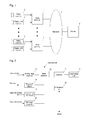
- Fig. 1 is a schematic diagram illustrating a configuration of the distributed image processing system.
- an area terminal 1 a video camera 2, and a digital still camera 3 are installed in each monitoring target area where a suspicious person or an abandoned substance (a suspicious substance) is monitored.
- a server 4 is installed in a center.
- the area terminal 1 installed in each monitoring target area is communicably connected to the server 4 through a network 5.
- the video camera 2 and the digital still camera 3 input a captured image to the area terminal 1.
- the video camera 2 is installed such that an image capturing area of the video camera 2 covers the whole monitoring target area.
- the image capturing area of the video camera 2 is the monitoring target area.
- the video camera 2 inputs a moving image (for example, the captured image of 30 frames per second) of the monitoring target area to the area terminal 1.
- the digital still camera 3 is attached to a panhead (not illustrated) that turns separately in two axial directions (a pan direction and a tilt direction) orthogonal to each other.
- the digital still camera 3 includes a zoom function of driving an image capturing optical system to change an image capturing magnification.
- the digital still camera 3 captures a still image in response to an input of a release signal.
- the video camera 2 corresponds to the first camera of the present invention
- the digital still camera 3 corresponds to the second camera of the present invention.
- the area terminal 1 processes the image (the moving image) captured by the video camera 2, and detects whether an object of which the image is captured is present, namely, whether the object is located in the monitoring target area.
- the area terminal 1 focuses an image capturing visual field of the digital still camera 3 on the detected object, and inputs the release signal to the digital still camera 3.
- the area terminal 1 transmits the image (the still image) captured by the digital still camera 3 to the server 4 through the network 5.
- the server 4 processes the still image transmitted from the area terminal 1, and detects an attribute such as a kind and a size of the object of which the image is captured (namely, the object located in the monitoring target area).
- the server 4 performs an output according to a detection result of the object located in the monitoring target area (the object detected by the area terminal 1).
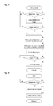
- Fig. 2 is a block diagram illustrating a configuration of a main part of the area terminal.
- the area terminal 1 includes a controller 11, a moving image input unit 12, an image processor 13, an image capturing visual field controller 14, an image capturing instruction unit 15, a still image input unit 16, an image storage unit 17, and a communication unit 18.
- the controller 11 controls operation of each unit in a main body of the area terminal 1.
- the moving image of the monitoring target area which is captured by the video camera 2, is input to the moving image input unit 12.
- the video camera 2 inputs the captured image of 30 frames per second to the moving image input unit 12.
- the image processor 13 generates a difference image between a frame image and a background image of the monitoring target area in each frame image input to the moving image input unit 12, and detects whether the image of the object (the suspicious person or the suspicious substance) located in the monitoring target area is captured from the generated difference image. According to well known techniques, the object such as the suspicious person and the suspicious substance which is located in the monitoring target area emerges in the difference image.
- the image capturing visual field controller 14 controls the image capturing visual field of the digital still camera 3. Specifically, the image capturing visual field controller 14 controls separately turning angles of the pan direction and tilt direction of the panhead to which the digital still camera 3 is attached. A driving mechanism (not illustrated) that turns the panhead in the pan direction and tilt direction is provided in the panhead. That is, the image capturing visual field controller 14 controls the driving mechanism of the panhead to control the turning angles in the pan direction and tilt direction. An image capturing direction of the digital still camera 3 is changed by changing the turning angles of the panhead in the pan direction and tilt direction. The image capturing visual field controller 14 issues an instruction on the image capturing magnification to the digital still camera 3.
- the image capturing instruction unit 15 inputs the release signal to the digital still camera 3.
- the still image captured by the digital still camera 3 is input to the still image input unit 16.
- the image storage unit 17 includes a recording medium such as a hard disk in which the moving image of the monitoring target area captured by the video camera 2, namely, the moving image input to the moving image input unit 12 is stored.
- the communication unit 18 controls the communication with the server 4 through the network 5.
- Fig. 3 is a block diagram illustrating a configuration of a main part of the server.
- the server 4 includes a controller 41, a communication unit 42, an image processor 43, an image storage unit 44, and an output unit 45.
- the controller 41 controls the operation of each unit in a main body of the server 4.
- the communication unit 42 controls communication with the area terminal 1 through the network 5.
- the image processor 43 processes the still image transmitted from the area terminal 1, and detects the attribute such as the kind and the size of the object of which the image is captured.
- the image processor 43 performs image processing such as well-known pattern matching to detect the attribute such as the kind and the size of the object of which the image is captured.
- the image processor 43 performs face recognition processing to estimate sexuality, age, and the like.
- the image processor 43 performs character recognition processing to recognize a license plate number indicated in a license plate.
- the still image transmitted from the area terminal 1 is stored in the image storage unit 44.
- the output unit 45 performs the output based on an image processing result of the image processor 43. For example, when detecting the suspicious person or the suspicious substance, the output unit 45 notifies a standby security guard by activating a warning of a security office with the kind or size of the detected suspicious person or suspicious substance as the processing result, or transmits the processing result to a portable terminal possessed by the security guard through electronic mail.
- the image capturing area of the video camera 2 corresponds to the monitoring target area allocated to the connected area terminal 1.
- the image capturing area of the video camera 2 is fixed.
- the size of the image capturing area of the digital still camera 3 can be changed by the image capturing magnification, and the digital still camera 3 can be focused on any position of the monitoring target area by changing the turning angles of the pan direction and tilt direction of the panhead to which the digital still camera 3 is attached.
- the digital still camera 3 cannot simultaneously capture the images of the two image capturing areas in Fig. 4 .
- Fig. 5 is a flowchart illustrating the operation of the area terminal.
- Fig. 6 is a flowchart illustrating the operation of the server.
- the area terminal 1 When the captured image (the frame image) is input from the video camera 2 to the moving image input unit 12 (S1), the area terminal 1 generates the difference image between the frame image and the background image of the monitoring target area (S2) in the image processor 13. The image processor 13 detects whether the object (the suspicious person or the suspicious substance) is located in the monitoring target area using the difference image generated in S2 (S3). The area terminal 1 returns to S1 when detecting that the object is not located in the monitoring target area in S3.
- the pieces of processing in S1 to S3 are performed in each frame image captured by the video camera 2.
- the pieces of processing in S1 to S3 may be performed in each 5 frames or 10 frames.
- the area terminal 1 detects the position (the position in the monitoring target area) and size of the object (S4).
- the position of the object in the monitoring target area can be detected from the position of the object on the frame image.
- the size of the object can be detected from the size of the object on the frame image.
- the image capturing visual field controller 14 calculates the turning angles in the pan direction and tilt direction of the panhead to which the digital still camera 3 is attached based on the position and size of the object detected in S4, and calculates the image capturing magnification of the digital still camera 3 (S5).
- S5 the turning angles in the pan direction and tilt direction and the image capturing magnification of the digital still camera 3 are calculated such that the whole object detected in S3 falls within the image capturing visual field of the digital still camera 3.
- the image capturing magnification of the digital still camera 3 can be enlarged compared with the image capturing magnification of the video camera 2. Accordingly, the image captured by the digital still camera 3 is better than the image captured by the video camera 2 in the clarity of the detected object.
- the image capturing visual field controller 14 issues an instruction on the turning angles of the panhead in the pan direction and tilt direction, which are calculated in S5, to the panhead to which the digital still camera 3 is attached, and issues an instruction on the image capturing magnification to the digital still camera 3 (S6). Therefore, the panhead turns in the pan direction and the tilt direction to change the image capturing direction of the digital still camera 3.
- the digital still camera 3 changes the image capturing magnification in accordance with the instruction currently issued.
- the image capturing instruction unit 15 inputs the release signal to the digital still camera 3 (S7). Therefore, the digital still camera 3 captures the image in the image capturing visual field at this point, and inputs the captured still image to the still image input unit 16. As described above, the area terminal 1 focuses the digital still camera 3 on the image capturing visual field according to the position or size of the currently-detected object, so that the digital still camera 3 can obtain the still image in which the clarity of the detected object is better than that of the frame image captured by the video camera 2.
- the area terminal 1 transmits the still image to the server 4 (S9). At this point, the area terminal 1 also transmits the object position detected in S4 and the image capturing magnification of the digital still camera 3, which is calculated in S5, to the server 4.
- the area terminal 1 may always store the moving image of the monitoring target area, which is input to the moving image input unit 12 and captured by the video camera 2, in the image storage unit 17.
- the area terminal 1 may store the moving image of the monitoring target area, which is input to the moving image input unit 12 and captured by the video camera 2, in the image storage unit 17 for a given time period from a time at which the object is detected in S3 as a start time.
- an image processing load on the image processor 13 that detects the object and a processing load of the transmission of the image to the server 4 are sufficiently reduced.
- the image processor 43 processes the currently-received still image (S12).
- S12 unlike the image processor 13 of the area terminal 1, the image processing involved in the pattern matching is performed to detect the attribute such as the kind or size of the object of which the image is captured in the currently-received still image.
- the image processor 43 detects whether the object of which the image is captured is a mobile object such as the person and the vehicle or the non-mobile object such as a bag and a suitcase through the pattern matching.
- the image processor 43 when the detected object is the person, the image processor 43 performs the face recognition processing to estimate the sexuality, the age, and the like.
- the image processor 43 when the detected object is the vehicle, the image processor 43 performs the character recognition processing of recognizing the license plate number indicated in the license plate of the vehicle.
- the communication unit 42 receives the image capturing magnification of the still image captured by the digital still camera 3 from the area terminal 1, so that the actual size of the object can be calculated from the size of the object on the still image.
- the output unit 45 performs the output according to the detection result in S12 (S13). For example, with the kind or size of the currently-detected suspicious person or suspicious substance as the processing result, the warning of the security office is activated to notify the standby security guard and the like, or the processing result is transmitted to the portable terminal possessed by the security guard through electronic mail.
- the still image that is transmitted from the area terminal 1 connected through the network 5 is stored in the image storage unit 44.
- the image processing load on the image processor 13 that detects the object and the processing load of the transmission of the image to the server 4 are sufficiently reduced.
- the attribute of the object detected by the area terminal 1 is detected on the side of the server 4.
- the server 4 does not detect whether the object is present.
- the still image, which is used by the server 4 in order to detect the attribute of the object is the image in which the object detected by the digital still camera 3 is clearly captured. Therefore, the server 4 can accurately detect the attribute of the object located in the monitoring target area.
- the area terminal 1 transmits the still image in which the detected object is captured to the server 4, but does not transmit the moving image captured by the video camera 2 to the server 4, so that a traffic volume of the network 5 can also be reduced.
- the inexpensive area terminal 1 having low processing performance can be used without any difficulty.
- the object located in the monitoring target area and the attribute of the object can accurately be detected on the side of the server 4. Therefore, the object located in the monitoring target area and the attribute of the object can accurately be detected, and the increase in cost of the system construction can be prevented.
- the digital still camera 3, the panhead, and the image capturing visual field controller 14, the image capturing instruction unit 15, and the still image input unit 16 of the area terminal 1 may be eliminated, and the frame image in which the object detected by the area terminal 1 is captured by the video camera 2 may be transmitted as the still image to the server 4. Therefore, the processing load on the area terminal 1 can further be reduced.
- the area terminal 1 may be configured to transmit to the server 4 the frame image of the video camera 2 in which the detected object is captured and the still image of the digital still camera 3 in which the detected object is captured.
- the area terminal 1 may be configured to detect whether the detected object is the mobile object or the non-mobile object, and notify the server 4.
- the area terminal 1 can detect whether the detected object is the mobile object or the non-mobile object based on whether the position of the object changes with time. Therefore, the server 4 performs the pattern matching of the object of which the image is captured in the still image while focusing on the mobile object or non-mobile object of which the server 4 is notified by the area terminal 1. That is, the image processing load can also be reduced on the side of the server 4.
Landscapes
- Engineering & Computer Science (AREA)
- Multimedia (AREA)
- Signal Processing (AREA)
- Theoretical Computer Science (AREA)
- Physics & Mathematics (AREA)
- General Physics & Mathematics (AREA)
- Artificial Intelligence (AREA)
- Software Systems (AREA)
- Human Computer Interaction (AREA)
- Computer Vision & Pattern Recognition (AREA)
- Computing Systems (AREA)
- General Engineering & Computer Science (AREA)
- Closed-Circuit Television Systems (AREA)
- Alarm Systems (AREA)
- Two-Way Televisions, Distribution Of Moving Picture Or The Like (AREA)
- Image Analysis (AREA)
Abstract
Description
- The present invention relates to a distributed image processing system, in which a terminal and a server perform image processing involved in detection of an object located in a monitoring target area and detection of an attribute such as the kind or size of the detected object in a distributed manner.
- Conventionally, a video camera (a monitoring camera) is installed in various places such as a school and a factory in order to monitor a suspicious person or a suspicious substance (an abandoned substance). For example, in order to secure reassurance and security against the suspicious person or the suspicious substance, the video camera is installed while focusing an image capturing area of the video camera on an entrance of facilities such as the school and the factory. The suspicious person or the suspicious substance is detected by processing an image captured by the monitoring camera, or the image (a moving image) captured by the video camera is recorded.
-
Patent Documents Patent Documents Patent Documents Patent Document 2, an electronic mail to which the still image captured by the digital still camera is attached is transmitted to a portable terminal such as a mobile phone which is possessed by a security guard and the like, thereby speeding up response to the detected mobile object. -
- Patent Document 1: Japanese Unexamined Patent Publication No.
2009-38779 - Patent Document 2: Japanese Unexamined Patent Publication No.
2010-177893 - However, in
Patent Documents Patent Documents - Nowadays, because a high value is placed on the securing of the reassurance and security against terrorist act and the like, there is also demand to discover the abandoned suspicious substance or speed up response to the suspicious substance.
- Although the attribute such as the kind or size of the object of which image is captured by the video camera is detected by well-known image processing such as pattern matching, it is necessary to use relatively complicated image processing in order to enhance the detection accuracy of the attribute of the object. As a result, a load increases on a device side that performs the image processing. That is, for the device that performs the image processing, it is necessary to use the device having a relatively high processing performance. On the other hand, in a relatively large facility, a plurality of monitoring target areas where the suspicious person or the suspicious substance is monitored are set, and the video camera is installed in each monitoring target area. The use of the terminal having the processing performance suitable for the image processing of the image captured by the video camera in each video camera (in each monitoring target area) increases cost of system construction.
- An object of the present invention is to provide a distributed image processing system that accurately detects the object located in the monitoring target area and the attribute of the object and prevents the increase in cost of the system construction.
- A distributed image processing system according to the present invention has the following configuration in order to solve the problem to achieve the object.
- The distributed image processing system includes a terminal and a server, the terminal and the server being communicably connected to each other. One or a plurality of terminals may communicably be connected to the server.
- A first camera is connected to the terminal. The first camera inputs a captured moving image of a monitoring target area to a moving image input unit of the terminal. In the terminal, a simple image processor processes the moving image input to the moving image input unit, and detects an object of which an image is captured. The simple image processor only has to detect whether the object of which the image is captured is present, but the simple image processor need not to detect an attribute such as a kind or a size of the object. For example, the simple image processor generates a difference image between a frame image of the moving image input to the moving image input unit and a background image of the monitoring target area, and detects whether the object is present based on the difference image. That is, the simple image processor performs image processing having a small processing load. When the simple image processor detects the object, the still image transmitting unit transmits the still image in which the detected object is captured to the server.
- In the server, an image processor processes the still image transmitted from the terminal, and detects an attribute of the object of which the still image is captured. The image processor detects the kind of the object of which the still image is captured through pattern matching, and performs recognition processing according to the kind of the detected object. For example, when the detected object is the suspicious person, the attribute such as sexuality and age of the suspicious person is detected by face recognition, and when the detected object is the vehicle, a license plate number indicated in a license plate of the vehicle is recognized by character recognition. In the server, an output unit performs an output based on a processing result of the image processor. For example, a warning of a security office is activated to notify the security guard and the like of a processing result, or the processing result is transmitted to a portable terminal possessed by the security guard and the like through electronic mail. Therefore, the response to the detected suspicious person or suspicious substance can quickly be taken.
- The terminal only has to be able to detect whether the image of the object is captured by the first camera (whether the object is present), but the terminal may not detect the attribute such as the kind or size of the object of which the image is captured, so that the image processing load involved in the detection of the object can sufficiently be reduced. The terminal transmits the image in which the object is captured to the server when the object is detected, and the terminal does not transmit the image in which the object is captured to the server when the object is not detected. Additionally, the terminal transmits not the moving image but the still image to the server. Therefore, in the terminal, because a data amount of the image transmitted to the server is also reduced, the load on the communication with the server is reduced. A traffic volume of the network that communicably connects the terminal and the server is also reduced.
- Accordingly, the inexpensive terminal having low processing performance can be used without any difficulty. The object located in the monitoring target area and the attribute of the object are accurately detected on the server side. That is, the object located in the monitoring target area and the attribute of the object are accurately detected, and the increase in cost of the system construction is prevented.
- The terminal may include an image capturing visual field controller configured to control an image capturing visual field of a second camera that captures the still image. As used herein, the image capturing visual field means an image capturing direction, an image capturing magnification, and the like. For example, the second camera may be attached to a panhead that turns separately in two axial directions (a pan direction and a tilt direction) orthogonal to each other, and the image capturing visual field controller may separately control turning angles of the panhead in the pan direction and the tilt direction to control the image capturing direction of the second camera. The second camera may include a zoom function, and the image capturing visual field controller may control the image capturing magnification of the second camera.
- In this case, the simple image processor may detect the object of which the image is captured, and detect a position of the object detected in the monitoring target area, and the image capturing visual field controller may control the image capturing visual field (such as the image capturing direction and the image capturing magnification) of the second camera based on the position of the object in the monitoring target area, the position of the object being detected by the simple image processor. Therefore, the image of the detected object can clearly be captured by the second camera. The still image transmitting unit transmits the still image captured by the second camera to the server. Therefore, the server more accurately detects the attribute of the object.
- In the terminal, the simple image processor may detect the object of which the image is captured, and detect whether the detected object is a mobile object, and the still image transmitting unit may transmit whether the detected object is a mobile object to the server together with the still image.
- According to the present invention, the object located in the monitoring target area and the attribute of the object are accurately detected, and the increase in cost of the system construction is prevented.
-
-
Fig. 1 is a schematic diagram illustrating a configuration of a distributed image processing system. -
Fig. 2 is a block diagram illustrating a configuration of a main part of an area terminal. -
Fig. 3 is a block diagram illustrating a configuration of a main part of a server. -
Fig. 4 is a view illustrating a relationship between an image capturing area of a video camera and an image capturing area of a digital still camera. -
Fig. 5 is a flowchart illustrating operation of the area terminal. -
Fig. 6 is a flowchart illustrating operation of the server. - A distributed image processing system according to an embodiment of the present invention will be described below.
-
Fig. 1 is a schematic diagram illustrating a configuration of the distributed image processing system. In the distributed image processing system, anarea terminal 1, avideo camera 2, and a digitalstill camera 3 are installed in each monitoring target area where a suspicious person or an abandoned substance (a suspicious substance) is monitored. Aserver 4 is installed in a center. Thearea terminal 1 installed in each monitoring target area is communicably connected to theserver 4 through anetwork 5. - The
video camera 2 and the digitalstill camera 3 input a captured image to thearea terminal 1. Thevideo camera 2 is installed such that an image capturing area of thevideo camera 2 covers the whole monitoring target area. In other words, the image capturing area of thevideo camera 2 is the monitoring target area. Thevideo camera 2 inputs a moving image (for example, the captured image of 30 frames per second) of the monitoring target area to thearea terminal 1. - The digital
still camera 3 is attached to a panhead (not illustrated) that turns separately in two axial directions (a pan direction and a tilt direction) orthogonal to each other. The digitalstill camera 3 includes a zoom function of driving an image capturing optical system to change an image capturing magnification. The digitalstill camera 3 captures a still image in response to an input of a release signal. - The
video camera 2 corresponds to the first camera of the present invention, and the digitalstill camera 3 corresponds to the second camera of the present invention. - The
area terminal 1 processes the image (the moving image) captured by thevideo camera 2, and detects whether an object of which the image is captured is present, namely, whether the object is located in the monitoring target area. When detecting the object located in the monitoring target area, thearea terminal 1 focuses an image capturing visual field of the digitalstill camera 3 on the detected object, and inputs the release signal to the digitalstill camera 3. Thearea terminal 1 transmits the image (the still image) captured by the digitalstill camera 3 to theserver 4 through thenetwork 5. - The
server 4 processes the still image transmitted from thearea terminal 1, and detects an attribute such as a kind and a size of the object of which the image is captured (namely, the object located in the monitoring target area). Theserver 4 performs an output according to a detection result of the object located in the monitoring target area (the object detected by the area terminal 1). -
Fig. 2 is a block diagram illustrating a configuration of a main part of the area terminal. Thearea terminal 1 includes acontroller 11, a movingimage input unit 12, animage processor 13, an image capturingvisual field controller 14, an image capturinginstruction unit 15, a stillimage input unit 16, animage storage unit 17, and acommunication unit 18. Thecontroller 11 controls operation of each unit in a main body of thearea terminal 1. - The moving image of the monitoring target area, which is captured by the
video camera 2, is input to the movingimage input unit 12. Thevideo camera 2 inputs the captured image of 30 frames per second to the movingimage input unit 12. - The
image processor 13 generates a difference image between a frame image and a background image of the monitoring target area in each frame image input to the movingimage input unit 12, and detects whether the image of the object (the suspicious person or the suspicious substance) located in the monitoring target area is captured from the generated difference image. According to well known techniques, the object such as the suspicious person and the suspicious substance which is located in the monitoring target area emerges in the difference image. - The image capturing
visual field controller 14 controls the image capturing visual field of the digitalstill camera 3. Specifically, the image capturingvisual field controller 14 controls separately turning angles of the pan direction and tilt direction of the panhead to which the digitalstill camera 3 is attached. A driving mechanism (not illustrated) that turns the panhead in the pan direction and tilt direction is provided in the panhead. That is, the image capturingvisual field controller 14 controls the driving mechanism of the panhead to control the turning angles in the pan direction and tilt direction. An image capturing direction of the digitalstill camera 3 is changed by changing the turning angles of the panhead in the pan direction and tilt direction. The image capturingvisual field controller 14 issues an instruction on the image capturing magnification to the digitalstill camera 3. - The image capturing
instruction unit 15 inputs the release signal to the digitalstill camera 3. - The still image captured by the digital
still camera 3 is input to the stillimage input unit 16. - The
image storage unit 17 includes a recording medium such as a hard disk in which the moving image of the monitoring target area captured by thevideo camera 2, namely, the moving image input to the movingimage input unit 12 is stored. - The
communication unit 18 controls the communication with theserver 4 through thenetwork 5. -
Fig. 3 is a block diagram illustrating a configuration of a main part of the server. Theserver 4 includes acontroller 41, acommunication unit 42, animage processor 43, animage storage unit 44, and anoutput unit 45. Thecontroller 41 controls the operation of each unit in a main body of theserver 4. - The
communication unit 42 controls communication with thearea terminal 1 through thenetwork 5. - The
image processor 43 processes the still image transmitted from thearea terminal 1, and detects the attribute such as the kind and the size of the object of which the image is captured. Theimage processor 43 performs image processing such as well-known pattern matching to detect the attribute such as the kind and the size of the object of which the image is captured. When the detected object is a person, theimage processor 43 performs face recognition processing to estimate sexuality, age, and the like. When the detected object is a vehicle, theimage processor 43 performs character recognition processing to recognize a license plate number indicated in a license plate. - The still image transmitted from the
area terminal 1 is stored in theimage storage unit 44. - The
output unit 45 performs the output based on an image processing result of theimage processor 43. For example, when detecting the suspicious person or the suspicious substance, theoutput unit 45 notifies a standby security guard by activating a warning of a security office with the kind or size of the detected suspicious person or suspicious substance as the processing result, or transmits the processing result to a portable terminal possessed by the security guard through electronic mail. - A relationship between the image capturing area of the
video camera 2 and the image capturing area of the digitalstill camera 3 will be described with reference toFig. 4 . As described above, the image capturing area of thevideo camera 2 corresponds to the monitoring target area allocated to the connectedarea terminal 1. The image capturing area of thevideo camera 2 is fixed. On the other hand, the size of the image capturing area of the digitalstill camera 3 can be changed by the image capturing magnification, and the digitalstill camera 3 can be focused on any position of the monitoring target area by changing the turning angles of the pan direction and tilt direction of the panhead to which the digitalstill camera 3 is attached. - The digital
still camera 3 cannot simultaneously capture the images of the two image capturing areas inFig. 4 . - The operation of the distributed image processing system will be described with reference to
Figs. 5 and 6. Fig. 5 is a flowchart illustrating the operation of the area terminal.Fig. 6 is a flowchart illustrating the operation of the server. - When the captured image (the frame image) is input from the
video camera 2 to the moving image input unit 12 (S1), thearea terminal 1 generates the difference image between the frame image and the background image of the monitoring target area (S2) in theimage processor 13. Theimage processor 13 detects whether the object (the suspicious person or the suspicious substance) is located in the monitoring target area using the difference image generated in S2 (S3). Thearea terminal 1 returns to S1 when detecting that the object is not located in the monitoring target area in S3. - In the embodiment, the pieces of processing in S1 to S3 are performed in each frame image captured by the
video camera 2. Alternatively, for example, the pieces of processing in S1 to S3 may be performed in each 5 frames or 10 frames. - If the object located in the monitoring target area is detected in S3, the
area terminal 1 detects the position (the position in the monitoring target area) and size of the object (S4). The position of the object in the monitoring target area can be detected from the position of the object on the frame image. The size of the object can be detected from the size of the object on the frame image. - The image capturing
visual field controller 14 calculates the turning angles in the pan direction and tilt direction of the panhead to which the digitalstill camera 3 is attached based on the position and size of the object detected in S4, and calculates the image capturing magnification of the digital still camera 3 (S5). In S5, the turning angles in the pan direction and tilt direction and the image capturing magnification of the digitalstill camera 3 are calculated such that the whole object detected in S3 falls within the image capturing visual field of the digitalstill camera 3. - Because it is sufficient for the digital
still camera 3 to capture only the image of the detected object, not the image of the whole monitoring target area, the image capturing magnification of the digitalstill camera 3 can be enlarged compared with the image capturing magnification of thevideo camera 2. Accordingly, the image captured by the digitalstill camera 3 is better than the image captured by thevideo camera 2 in the clarity of the detected object. - The image capturing
visual field controller 14 issues an instruction on the turning angles of the panhead in the pan direction and tilt direction, which are calculated in S5, to the panhead to which the digitalstill camera 3 is attached, and issues an instruction on the image capturing magnification to the digital still camera 3 (S6). Therefore, the panhead turns in the pan direction and the tilt direction to change the image capturing direction of the digitalstill camera 3. The digitalstill camera 3 changes the image capturing magnification in accordance with the instruction currently issued. - In the
area terminal 1, the image capturinginstruction unit 15 inputs the release signal to the digital still camera 3 (S7). Therefore, the digitalstill camera 3 captures the image in the image capturing visual field at this point, and inputs the captured still image to the stillimage input unit 16. As described above, thearea terminal 1 focuses the digitalstill camera 3 on the image capturing visual field according to the position or size of the currently-detected object, so that the digitalstill camera 3 can obtain the still image in which the clarity of the detected object is better than that of the frame image captured by thevideo camera 2. - When the still image captured by the digital
still camera 3 is input (S8), thearea terminal 1 transmits the still image to the server 4 (S9). At this point, thearea terminal 1 also transmits the object position detected in S4 and the image capturing magnification of the digitalstill camera 3, which is calculated in S5, to theserver 4. - The
area terminal 1 may always store the moving image of the monitoring target area, which is input to the movingimage input unit 12 and captured by thevideo camera 2, in theimage storage unit 17. Alternatively, in order to reduce a storage capacity of theimage storage unit 17, thearea terminal 1 may store the moving image of the monitoring target area, which is input to the movingimage input unit 12 and captured by thevideo camera 2, in theimage storage unit 17 for a given time period from a time at which the object is detected in S3 as a start time. - Based on the above description, in the
area terminal 1, an image processing load on theimage processor 13 that detects the object and a processing load of the transmission of the image to theserver 4 are sufficiently reduced. - The operation of the
server 4 will be described with reference toFig. 6 . - In the
server 4, when thecommunication unit 42 receives the still image transmitted from thearea terminal 1 connected through the network 5 (S11), theimage processor 43 processes the currently-received still image (S12). In S12, unlike theimage processor 13 of thearea terminal 1, the image processing involved in the pattern matching is performed to detect the attribute such as the kind or size of the object of which the image is captured in the currently-received still image. Specifically, in theserver 4, theimage processor 43 detects whether the object of which the image is captured is a mobile object such as the person and the vehicle or the non-mobile object such as a bag and a suitcase through the pattern matching. In theserver 4, when the detected object is the person, theimage processor 43 performs the face recognition processing to estimate the sexuality, the age, and the like. In theserver 4, when the detected object is the vehicle, theimage processor 43 performs the character recognition processing of recognizing the license plate number indicated in the license plate of the vehicle. - In the
server 4, thecommunication unit 42 receives the image capturing magnification of the still image captured by the digitalstill camera 3 from thearea terminal 1, so that the actual size of the object can be calculated from the size of the object on the still image. - Because the pattern matching, the face recognition processing, and the character recognition processing are well known, the detailed description is omitted.
- In the
server 4, theoutput unit 45 performs the output according to the detection result in S12 (S13). For example, with the kind or size of the currently-detected suspicious person or suspicious substance as the processing result, the warning of the security office is activated to notify the standby security guard and the like, or the processing result is transmitted to the portable terminal possessed by the security guard through electronic mail. - In the
server 4, the still image that is transmitted from thearea terminal 1 connected through thenetwork 5 is stored in theimage storage unit 44. - As described above, in the
area terminal 1, the image processing load on theimage processor 13 that detects the object and the processing load of the transmission of the image to theserver 4 are sufficiently reduced. - The attribute of the object detected by the
area terminal 1 is detected on the side of theserver 4. Theserver 4 does not detect whether the object is present. The still image, which is used by theserver 4 in order to detect the attribute of the object, is the image in which the object detected by the digitalstill camera 3 is clearly captured. Therefore, theserver 4 can accurately detect the attribute of the object located in the monitoring target area. Thearea terminal 1 transmits the still image in which the detected object is captured to theserver 4, but does not transmit the moving image captured by thevideo camera 2 to theserver 4, so that a traffic volume of thenetwork 5 can also be reduced. - Accordingly, in the distributed image processing system, the
inexpensive area terminal 1 having low processing performance can be used without any difficulty. The object located in the monitoring target area and the attribute of the object can accurately be detected on the side of theserver 4. Therefore, the object located in the monitoring target area and the attribute of the object can accurately be detected, and the increase in cost of the system construction can be prevented. - Alternatively, the digital
still camera 3, the panhead, and the image capturingvisual field controller 14, the image capturinginstruction unit 15, and the stillimage input unit 16 of thearea terminal 1 may be eliminated, and the frame image in which the object detected by thearea terminal 1 is captured by thevideo camera 2 may be transmitted as the still image to theserver 4. Therefore, the processing load on thearea terminal 1 can further be reduced. - The
area terminal 1 may be configured to transmit to theserver 4 the frame image of thevideo camera 2 in which the detected object is captured and the still image of the digitalstill camera 3 in which the detected object is captured. - The
area terminal 1 may be configured to detect whether the detected object is the mobile object or the non-mobile object, and notify theserver 4. Thearea terminal 1 can detect whether the detected object is the mobile object or the non-mobile object based on whether the position of the object changes with time. Therefore, theserver 4 performs the pattern matching of the object of which the image is captured in the still image while focusing on the mobile object or non-mobile object of which theserver 4 is notified by thearea terminal 1. That is, the image processing load can also be reduced on the side of theserver 4. -
- 1
- area terminal
- 2
- video camera
- 3
- digital still camera
- 4
- server
- 5
- network
- 11
- controller
- 12
- moving image input unit
- 13
- image processor
- 14
- image capturing visual field controller
- 15
- image capturing instruction unit
- 16
- still image input unit
- 17
- image storage unit
- 18
- communication unit
- 41
- controller
- 42
- communication unit
- 43
- image processor
- 44
- image storage unit
- 45
- output unit
Claims (5)
- A distributed image processing system comprising a terminal and a server, the terminal and the server being communicably connected to each other, wherein
the terminal comprises:a moving image input unit to which a moving image in a monitoring target area is input, the moving image being captured by a first camera;a simple image processor configured to process the moving image input to the moving image input unit, and detect an object of which an image is captured; anda still image transmitting unit configured to transmit an image in which the detected object is captured to the server in a form of a still image when the simple image processor detects the object, andthe server comprises:an image processor configured to process the still image transmitted from the terminal, and detect an attribute of the object of which the still image is captured; andan output unit configured to perform an output based on a processing result of the image processor. - The distributed image processing system according to claim 1, wherein
the terminal comprises an image capturing visual field controller configured to control an image capturing visual field of a second camera that captures the still image,
the simple image processor detects the object of which the image is captured, and detects a position of the object detected in the monitoring target area,
the image capturing visual field controller controls the image capturing visual field of the second camera based on the position of the object in the monitoring target area, the position of the object being detected by the simple image processor, and
the still image transmitting unit transmits the still image captured by the second camera to the server. - The distributed image processing system according to claim 1 or 2, wherein, in the terminal, the simple image processor detects the object of which the image is captured, and detects whether the detected object is a mobile object, and
the still image transmitting unit transmits whether the detected object is a mobile object to the server together with the still image. - The distributed image processing system according to any one of claims 1 to 3, wherein, in the terminal, the simple image processor detects the object of which the image is captured, by generating a difference image between a frame image of the moving image input to the moving image input unit and a background image of the monitoring target area.
- The distributed image processing system according to any one of claims 1 to 4, wherein, in the server, the image processor detects a kind of the object of which the still image is captured, through pattern matching.
Applications Claiming Priority (2)
| Application Number | Priority Date | Filing Date | Title |
|---|---|---|---|
| JP2011127812 | 2011-06-08 | ||
| PCT/JP2012/054068 WO2012169232A1 (en) | 2011-06-08 | 2012-02-21 | Distributed image processing system |
Publications (3)
| Publication Number | Publication Date |
|---|---|
| EP2720459A1 true EP2720459A1 (en) | 2014-04-16 |
| EP2720459A4 EP2720459A4 (en) | 2015-04-22 |
| EP2720459B1 EP2720459B1 (en) | 2020-07-08 |
Family
ID=47295806
Family Applications (1)
| Application Number | Title | Priority Date | Filing Date |
|---|---|---|---|
| EP12796757.8A Not-in-force EP2720459B1 (en) | 2011-06-08 | 2012-02-21 | Distributed image processing system |
Country Status (5)
| Country | Link |
|---|---|
| US (1) | US20140146172A1 (en) |
| EP (1) | EP2720459B1 (en) |
| JP (1) | JP5790761B2 (en) |
| CN (1) | CN103548341A (en) |
| WO (1) | WO2012169232A1 (en) |
Cited By (2)
| Publication number | Priority date | Publication date | Assignee | Title |
|---|---|---|---|---|
| WO2015188035A1 (en) * | 2014-06-05 | 2015-12-10 | Promethean Limited | Systems and methods for detecting, identifying and tracking objects and events over time |
| US9269159B2 (en) | 2014-06-05 | 2016-02-23 | Promethean Limited | Systems and methods for tracking object association over time |
Families Citing this family (23)
| Publication number | Priority date | Publication date | Assignee | Title |
|---|---|---|---|---|
| US20140203947A1 (en) * | 2013-01-20 | 2014-07-24 | Alan Haddy | Storage and recall of buried asset data over communications networks for damage avoidance and mapping |
| JP2016129269A (en) * | 2013-04-22 | 2016-07-14 | パナソニック株式会社 | Video/audio processing device, integrated circuit and program |
| CN104092941A (en) * | 2014-07-10 | 2014-10-08 | 深圳市得意自动化科技有限公司 | Camera shooting method achieved through camera shooting elements |
| US10367985B2 (en) | 2014-07-23 | 2019-07-30 | Orcam Technologies Ltd. | Wearable apparatus and method for processing images including product descriptors |
| JP2016134103A (en) * | 2015-01-21 | 2016-07-25 | 富士ゼロックス株式会社 | Monitoring system |
| JP6266577B2 (en) * | 2015-10-02 | 2018-01-24 | 京セラ株式会社 | Electronics |
| JP6241796B2 (en) * | 2015-12-25 | 2017-12-06 | パナソニックIpマネジメント株式会社 | Left item monitoring device, left item monitoring system including the same, and left item monitoring method |
| WO2018116494A1 (en) * | 2016-12-22 | 2018-06-28 | 日本電気株式会社 | Monitoring camera, monitoring system, method for controlling monitoring camera, and program |
| US10885788B2 (en) * | 2017-04-24 | 2021-01-05 | Mitsubishi Electric Corporation | Notification control apparatus and method for controlling notification |
| JP6948175B2 (en) * | 2017-07-06 | 2021-10-13 | キヤノン株式会社 | Image processing device and its control method |
| JP2019125258A (en) * | 2018-01-18 | 2019-07-25 | アイシン・エィ・ダブリュ株式会社 | Information collecting system and information collecting program |
| JP7251247B2 (en) * | 2018-03-29 | 2023-04-04 | 株式会社リコー | Communication system and communication method |
| US10559200B1 (en) | 2018-05-01 | 2020-02-11 | Flock Group Inc. | Method and system for capturing and storing significant surveillance images |
| US10795933B1 (en) | 2018-05-01 | 2020-10-06 | Flock Group Inc. | System and method for object based query of video content captured by a dynamic surveillance network |
| CN111028313B (en) * | 2019-12-26 | 2020-10-09 | 浙江口碑网络技术有限公司 | Table distribution image generation method and device |
| JP7447626B2 (en) * | 2020-03-30 | 2024-03-12 | 大日本印刷株式会社 | Information processing method, information processing device, program and information processing system |
| JP7641980B2 (en) * | 2020-10-01 | 2025-03-07 | 富士フイルム株式会社 | Disaster information processing device, operation method of disaster information processing device, operation program of disaster information processing device, and disaster information processing system |
| CN116405773A (en) * | 2020-12-29 | 2023-07-07 | 华为技术有限公司 | A shooting method, system and electronic device |
| CN112991670A (en) * | 2021-02-04 | 2021-06-18 | 西安美格智联软件科技有限公司 | Fire-fighting dangerous area classification management and control method and system, storage medium and processing terminal |
| EP4099679A1 (en) * | 2021-05-31 | 2022-12-07 | Robert Bosch GmbH | Method and apparatus for operating a camera control system |
| US12132986B2 (en) * | 2021-12-12 | 2024-10-29 | Avanti R&D, Inc. | Computer vision system used in vehicles |
| TWI815495B (en) * | 2022-06-06 | 2023-09-11 | 仁寶電腦工業股份有限公司 | Dynamic image processing method, electronic device, and terminal device and mobile ommunication device connected thereto |
| US20250245989A1 (en) * | 2024-01-30 | 2025-07-31 | Alarm.Com Incorporated | Camera |
Family Cites Families (26)
| Publication number | Priority date | Publication date | Assignee | Title |
|---|---|---|---|---|
| JPH0944759A (en) * | 1995-07-28 | 1997-02-14 | Oki Electric Ind Co Ltd | Monitoring device |
| JPH11112966A (en) * | 1997-10-07 | 1999-04-23 | Canon Inc | Moving object detecting device, moving object detecting method, and computer-readable storage medium |
| US6731805B2 (en) * | 2001-03-28 | 2004-05-04 | Koninklijke Philips Electronics N.V. | Method and apparatus to distinguish deposit and removal in surveillance video |
| JP2003116139A (en) * | 2001-10-03 | 2003-04-18 | Olympus Optical Co Ltd | Video distribution server and video receiving client system |
| JP4156893B2 (en) * | 2002-09-27 | 2008-09-24 | 富士フイルム株式会社 | Image processing apparatus, method, and program |
| GB0226002D0 (en) * | 2002-11-07 | 2002-12-11 | Home Networking Ltd | Surveillance device |
| CN1194484C (en) * | 2003-01-30 | 2005-03-23 | 张健 | Real time monitoring and transferring methods of visible home safety and protection system |
| JP4140402B2 (en) * | 2003-03-03 | 2008-08-27 | 松下電工株式会社 | Image processing device |
| JP4622301B2 (en) * | 2004-05-07 | 2011-02-02 | オムロン株式会社 | Surveillance system and surveillance camera |
| JP4449782B2 (en) * | 2005-02-25 | 2010-04-14 | ソニー株式会社 | Imaging apparatus and image distribution method |
| JP2006332881A (en) * | 2005-05-24 | 2006-12-07 | Canon Inc | Surveillance photographing system, photographing method, computer program, and recording medium |
| CN100478862C (en) * | 2005-10-05 | 2009-04-15 | 索尼株式会社 | Display device and display method |
| JP4793025B2 (en) * | 2006-02-28 | 2011-10-12 | 株式会社日立製作所 | Distributed image processing device |
| CN100547351C (en) * | 2007-02-01 | 2009-10-07 | 华中科技大学 | A method of machine vision positioning |
| JP2008283629A (en) * | 2007-05-14 | 2008-11-20 | Sony Corp | Imaging apparatus, imaging signal processing method, and program |
| CN101329176A (en) * | 2007-06-20 | 2008-12-24 | 贝联特种金属制品(上海)有限公司 | On-line image detection system |
| JP4724888B2 (en) | 2007-08-06 | 2011-07-13 | 大阪府 | Moving body detection apparatus, moving body imaging system, moving body imaging method, and moving body detection program |
| JP4975679B2 (en) * | 2008-04-18 | 2012-07-11 | 株式会社Pfu | Notebook information processing apparatus and projective transformation parameter calculation method |
| CN101765025A (en) * | 2008-12-23 | 2010-06-30 | 北京中星微电子有限公司 | System for abnormal detection of surveillance camera and method thereof |
| JP5153669B2 (en) * | 2009-01-28 | 2013-02-27 | 大阪府 | Imaging control apparatus and imaging control method |
| JP4748250B2 (en) * | 2009-02-27 | 2011-08-17 | ソニー株式会社 | Image processing apparatus, image processing system, camera apparatus, image processing method, and program |
| CN102044064A (en) * | 2009-10-23 | 2011-05-04 | 鸿富锦精密工业(深圳)有限公司 | Image processing system and method |
| CN101833813B (en) * | 2010-03-03 | 2012-06-13 | 杭州创导安全技术有限公司 | ATM machine foreign intrusion detection alarming device and method |
| US9082278B2 (en) * | 2010-03-19 | 2015-07-14 | University-Industry Cooperation Group Of Kyung Hee University | Surveillance system |
| CN201750493U (en) * | 2010-07-02 | 2011-02-16 | 湖南云博信息技术有限公司 | Intelligent double CMOS camera |
| CN101969548B (en) * | 2010-10-15 | 2012-05-23 | 中国人民解放军国防科学技术大学 | Active video acquisition method and device based on binocular camera |
-
2012
- 2012-02-21 WO PCT/JP2012/054068 patent/WO2012169232A1/en not_active Ceased
- 2012-02-21 EP EP12796757.8A patent/EP2720459B1/en not_active Not-in-force
- 2012-02-21 JP JP2013519400A patent/JP5790761B2/en not_active Expired - Fee Related
- 2012-02-21 CN CN201280024655.1A patent/CN103548341A/en active Pending
- 2012-02-21 US US14/119,617 patent/US20140146172A1/en not_active Abandoned
Cited By (4)
| Publication number | Priority date | Publication date | Assignee | Title |
|---|---|---|---|---|
| WO2015188035A1 (en) * | 2014-06-05 | 2015-12-10 | Promethean Limited | Systems and methods for detecting, identifying and tracking objects and events over time |
| US9269159B2 (en) | 2014-06-05 | 2016-02-23 | Promethean Limited | Systems and methods for tracking object association over time |
| US9524418B2 (en) | 2014-06-05 | 2016-12-20 | Promethean Limited | Systems and methods for detecting, identifying and tracking objects and events over time |
| US9898647B2 (en) | 2014-06-05 | 2018-02-20 | Promethean Limited | Systems and methods for detecting, identifying and tracking objects and events over time |
Also Published As
| Publication number | Publication date |
|---|---|
| JP5790761B2 (en) | 2015-10-07 |
| EP2720459B1 (en) | 2020-07-08 |
| US20140146172A1 (en) | 2014-05-29 |
| JPWO2012169232A1 (en) | 2015-02-23 |
| EP2720459A4 (en) | 2015-04-22 |
| CN103548341A (en) | 2014-01-29 |
| WO2012169232A1 (en) | 2012-12-13 |
Similar Documents
| Publication | Publication Date | Title |
|---|---|---|
| EP2720459B1 (en) | Distributed image processing system | |
| EP3754618B1 (en) | Recording control device, recording control system, recording control method, and recording control program | |
| US8339469B2 (en) | Process for automatically determining a probability of image capture with a terminal using contextual data | |
| US12010414B2 (en) | Lens water dispersion | |
| US20210374447A1 (en) | Method and device for processing image, electronic equipment, and storage medium | |
| US9094597B2 (en) | Imaging apparatus and imaging system | |
| US9386050B2 (en) | Method and apparatus for filtering devices within a security social network | |
| KR101530255B1 (en) | Cctv system having auto tracking function of moving target | |
| US10083344B2 (en) | Facial recognition apparatus, recognition method and program therefor, and information device | |
| US9167048B2 (en) | Method and apparatus for filtering devices within a security social network | |
| US20100315508A1 (en) | Video monitoring system and method | |
| US20150116471A1 (en) | Method, apparatus and storage medium for passerby detection | |
| JP2013183433A (en) | Client terminal, server, and program | |
| CN108734066B (en) | Device and method for acquiring gesture image | |
| KR102054930B1 (en) | Method and apparatus for sharing picture in the system | |
| CN107211090A (en) | Operating device, tracking system, operating method and program | |
| JP2013021551A (en) | Detection device, detection method, and program | |
| US20190244019A1 (en) | Information processing device and information processing method | |
| US20140273989A1 (en) | Method and apparatus for filtering devices within a security social network | |
| JP2009206695A (en) | Imaging apparatus | |
| KR101698864B1 (en) | Media Being Recorded with the Program Executing Method for Detecting Image Using Metadata | |
| CN112153291B (en) | Photographing method and electronic equipment | |
| US9836644B2 (en) | Changing a depiction in a captured image based on a state of a subject present in the captured image | |
| KR20140030502A (en) | Site monitoring system | |
| KR20140121713A (en) | System for monitoring image and operating method thereof |
Legal Events
| Date | Code | Title | Description |
|---|---|---|---|
| PUAI | Public reference made under article 153(3) epc to a published international application that has entered the european phase |
Free format text: ORIGINAL CODE: 0009012 |
|
| 17P | Request for examination filed |
Effective date: 20131122 |
|
| AK | Designated contracting states |
Kind code of ref document: A1 Designated state(s): AL AT BE BG CH CY CZ DE DK EE ES FI FR GB GR HR HU IE IS IT LI LT LU LV MC MK MT NL NO PL PT RO RS SE SI SK SM TR |
|
| DAX | Request for extension of the european patent (deleted) | ||
| RA4 | Supplementary search report drawn up and despatched (corrected) |
Effective date: 20150323 |
|
| RIC1 | Information provided on ipc code assigned before grant |
Ipc: H04N 7/18 20060101AFI20150316BHEP Ipc: G08B 13/196 20060101ALI20150316BHEP Ipc: G06T 7/00 20060101ALI20150316BHEP Ipc: G08B 25/00 20060101ALI20150316BHEP Ipc: G06T 1/00 20060101ALI20150316BHEP |
|
| STAA | Information on the status of an ep patent application or granted ep patent |
Free format text: STATUS: EXAMINATION IS IN PROGRESS |
|
| 17Q | First examination report despatched |
Effective date: 20180626 |
|
| GRAP | Despatch of communication of intention to grant a patent |
Free format text: ORIGINAL CODE: EPIDOSNIGR1 |
|
| STAA | Information on the status of an ep patent application or granted ep patent |
Free format text: STATUS: GRANT OF PATENT IS INTENDED |
|
| INTG | Intention to grant announced |
Effective date: 20200305 |
|
| GRAS | Grant fee paid |
Free format text: ORIGINAL CODE: EPIDOSNIGR3 |
|
| GRAA | (expected) grant |
Free format text: ORIGINAL CODE: 0009210 |
|
| STAA | Information on the status of an ep patent application or granted ep patent |
Free format text: STATUS: THE PATENT HAS BEEN GRANTED |
|
| AK | Designated contracting states |
Kind code of ref document: B1 Designated state(s): AL AT BE BG CH CY CZ DE DK EE ES FI FR GB GR HR HU IE IS IT LI LT LU LV MC MK MT NL NO PL PT RO RS SE SI SK SM TR |
|
| REG | Reference to a national code |
Ref country code: GB Ref legal event code: FG4D |
|
| REG | Reference to a national code |
Ref country code: AT Ref legal event code: REF Ref document number: 1289752 Country of ref document: AT Kind code of ref document: T Effective date: 20200715 Ref country code: CH Ref legal event code: EP |
|
| REG | Reference to a national code |
Ref country code: DE Ref legal event code: R096 Ref document number: 602012071163 Country of ref document: DE |
|
| REG | Reference to a national code |
Ref country code: IE Ref legal event code: FG4D |
|
| REG | Reference to a national code |
Ref country code: LT Ref legal event code: MG4D |
|
| REG | Reference to a national code |
Ref country code: AT Ref legal event code: MK05 Ref document number: 1289752 Country of ref document: AT Kind code of ref document: T Effective date: 20200708 |
|
| REG | Reference to a national code |
Ref country code: NL Ref legal event code: MP Effective date: 20200708 |
|
| PG25 | Lapsed in a contracting state [announced via postgrant information from national office to epo] |
Ref country code: BG Free format text: LAPSE BECAUSE OF FAILURE TO SUBMIT A TRANSLATION OF THE DESCRIPTION OR TO PAY THE FEE WITHIN THE PRESCRIBED TIME-LIMIT Effective date: 20201008 Ref country code: NO Free format text: LAPSE BECAUSE OF FAILURE TO SUBMIT A TRANSLATION OF THE DESCRIPTION OR TO PAY THE FEE WITHIN THE PRESCRIBED TIME-LIMIT Effective date: 20201008 Ref country code: ES Free format text: LAPSE BECAUSE OF FAILURE TO SUBMIT A TRANSLATION OF THE DESCRIPTION OR TO PAY THE FEE WITHIN THE PRESCRIBED TIME-LIMIT Effective date: 20200708 Ref country code: GR Free format text: LAPSE BECAUSE OF FAILURE TO SUBMIT A TRANSLATION OF THE DESCRIPTION OR TO PAY THE FEE WITHIN THE PRESCRIBED TIME-LIMIT Effective date: 20201009 Ref country code: LT Free format text: LAPSE BECAUSE OF FAILURE TO SUBMIT A TRANSLATION OF THE DESCRIPTION OR TO PAY THE FEE WITHIN THE PRESCRIBED TIME-LIMIT Effective date: 20200708 Ref country code: PT Free format text: LAPSE BECAUSE OF FAILURE TO SUBMIT A TRANSLATION OF THE DESCRIPTION OR TO PAY THE FEE WITHIN THE PRESCRIBED TIME-LIMIT Effective date: 20201109 Ref country code: HR Free format text: LAPSE BECAUSE OF FAILURE TO SUBMIT A TRANSLATION OF THE DESCRIPTION OR TO PAY THE FEE WITHIN THE PRESCRIBED TIME-LIMIT Effective date: 20200708 Ref country code: AT Free format text: LAPSE BECAUSE OF FAILURE TO SUBMIT A TRANSLATION OF THE DESCRIPTION OR TO PAY THE FEE WITHIN THE PRESCRIBED TIME-LIMIT Effective date: 20200708 Ref country code: SE Free format text: LAPSE BECAUSE OF FAILURE TO SUBMIT A TRANSLATION OF THE DESCRIPTION OR TO PAY THE FEE WITHIN THE PRESCRIBED TIME-LIMIT Effective date: 20200708 Ref country code: FI Free format text: LAPSE BECAUSE OF FAILURE TO SUBMIT A TRANSLATION OF THE DESCRIPTION OR TO PAY THE FEE WITHIN THE PRESCRIBED TIME-LIMIT Effective date: 20200708 |
|
| PG25 | Lapsed in a contracting state [announced via postgrant information from national office to epo] |
Ref country code: IS Free format text: LAPSE BECAUSE OF FAILURE TO SUBMIT A TRANSLATION OF THE DESCRIPTION OR TO PAY THE FEE WITHIN THE PRESCRIBED TIME-LIMIT Effective date: 20201108 Ref country code: PL Free format text: LAPSE BECAUSE OF FAILURE TO SUBMIT A TRANSLATION OF THE DESCRIPTION OR TO PAY THE FEE WITHIN THE PRESCRIBED TIME-LIMIT Effective date: 20200708 Ref country code: RS Free format text: LAPSE BECAUSE OF FAILURE TO SUBMIT A TRANSLATION OF THE DESCRIPTION OR TO PAY THE FEE WITHIN THE PRESCRIBED TIME-LIMIT Effective date: 20200708 Ref country code: LV Free format text: LAPSE BECAUSE OF FAILURE TO SUBMIT A TRANSLATION OF THE DESCRIPTION OR TO PAY THE FEE WITHIN THE PRESCRIBED TIME-LIMIT Effective date: 20200708 |
|
| PG25 | Lapsed in a contracting state [announced via postgrant information from national office to epo] |
Ref country code: NL Free format text: LAPSE BECAUSE OF FAILURE TO SUBMIT A TRANSLATION OF THE DESCRIPTION OR TO PAY THE FEE WITHIN THE PRESCRIBED TIME-LIMIT Effective date: 20200708 |
|
| REG | Reference to a national code |
Ref country code: DE Ref legal event code: R097 Ref document number: 602012071163 Country of ref document: DE |
|
| PG25 | Lapsed in a contracting state [announced via postgrant information from national office to epo] |
Ref country code: EE Free format text: LAPSE BECAUSE OF FAILURE TO SUBMIT A TRANSLATION OF THE DESCRIPTION OR TO PAY THE FEE WITHIN THE PRESCRIBED TIME-LIMIT Effective date: 20200708 Ref country code: DK Free format text: LAPSE BECAUSE OF FAILURE TO SUBMIT A TRANSLATION OF THE DESCRIPTION OR TO PAY THE FEE WITHIN THE PRESCRIBED TIME-LIMIT Effective date: 20200708 Ref country code: CZ Free format text: LAPSE BECAUSE OF FAILURE TO SUBMIT A TRANSLATION OF THE DESCRIPTION OR TO PAY THE FEE WITHIN THE PRESCRIBED TIME-LIMIT Effective date: 20200708 Ref country code: IT Free format text: LAPSE BECAUSE OF FAILURE TO SUBMIT A TRANSLATION OF THE DESCRIPTION OR TO PAY THE FEE WITHIN THE PRESCRIBED TIME-LIMIT Effective date: 20200708 Ref country code: SM Free format text: LAPSE BECAUSE OF FAILURE TO SUBMIT A TRANSLATION OF THE DESCRIPTION OR TO PAY THE FEE WITHIN THE PRESCRIBED TIME-LIMIT Effective date: 20200708 Ref country code: RO Free format text: LAPSE BECAUSE OF FAILURE TO SUBMIT A TRANSLATION OF THE DESCRIPTION OR TO PAY THE FEE WITHIN THE PRESCRIBED TIME-LIMIT Effective date: 20200708 |
|
| PLBE | No opposition filed within time limit |
Free format text: ORIGINAL CODE: 0009261 |
|
| STAA | Information on the status of an ep patent application or granted ep patent |
Free format text: STATUS: NO OPPOSITION FILED WITHIN TIME LIMIT |
|
| PG25 | Lapsed in a contracting state [announced via postgrant information from national office to epo] |
Ref country code: AL Free format text: LAPSE BECAUSE OF FAILURE TO SUBMIT A TRANSLATION OF THE DESCRIPTION OR TO PAY THE FEE WITHIN THE PRESCRIBED TIME-LIMIT Effective date: 20200708 |
|
| 26N | No opposition filed |
Effective date: 20210409 |
|
| PG25 | Lapsed in a contracting state [announced via postgrant information from national office to epo] |
Ref country code: SK Free format text: LAPSE BECAUSE OF FAILURE TO SUBMIT A TRANSLATION OF THE DESCRIPTION OR TO PAY THE FEE WITHIN THE PRESCRIBED TIME-LIMIT Effective date: 20200708 |
|
| PG25 | Lapsed in a contracting state [announced via postgrant information from national office to epo] |
Ref country code: SI Free format text: LAPSE BECAUSE OF FAILURE TO SUBMIT A TRANSLATION OF THE DESCRIPTION OR TO PAY THE FEE WITHIN THE PRESCRIBED TIME-LIMIT Effective date: 20200708 |
|
| REG | Reference to a national code |
Ref country code: DE Ref legal event code: R119 Ref document number: 602012071163 Country of ref document: DE |
|
| PG25 | Lapsed in a contracting state [announced via postgrant information from national office to epo] |
Ref country code: MC Free format text: LAPSE BECAUSE OF FAILURE TO SUBMIT A TRANSLATION OF THE DESCRIPTION OR TO PAY THE FEE WITHIN THE PRESCRIBED TIME-LIMIT Effective date: 20200708 |
|
| REG | Reference to a national code |
Ref country code: BE Ref legal event code: MM Effective date: 20210228 |
|
| PG25 | Lapsed in a contracting state [announced via postgrant information from national office to epo] |
Ref country code: LU Free format text: LAPSE BECAUSE OF NON-PAYMENT OF DUE FEES Effective date: 20210221 Ref country code: LI Free format text: LAPSE BECAUSE OF NON-PAYMENT OF DUE FEES Effective date: 20210228 Ref country code: CH Free format text: LAPSE BECAUSE OF NON-PAYMENT OF DUE FEES Effective date: 20210228 |
|
| PG25 | Lapsed in a contracting state [announced via postgrant information from national office to epo] |
Ref country code: DE Free format text: LAPSE BECAUSE OF NON-PAYMENT OF DUE FEES Effective date: 20210901 Ref country code: FR Free format text: LAPSE BECAUSE OF NON-PAYMENT OF DUE FEES Effective date: 20210228 Ref country code: IE Free format text: LAPSE BECAUSE OF NON-PAYMENT OF DUE FEES Effective date: 20210221 |
|
| PGFP | Annual fee paid to national office [announced via postgrant information from national office to epo] |
Ref country code: GB Payment date: 20211231 Year of fee payment: 11 |
|
| PG25 | Lapsed in a contracting state [announced via postgrant information from national office to epo] |
Ref country code: BE Free format text: LAPSE BECAUSE OF NON-PAYMENT OF DUE FEES Effective date: 20210228 |
|
| PG25 | Lapsed in a contracting state [announced via postgrant information from national office to epo] |
Ref country code: HU Free format text: LAPSE BECAUSE OF FAILURE TO SUBMIT A TRANSLATION OF THE DESCRIPTION OR TO PAY THE FEE WITHIN THE PRESCRIBED TIME-LIMIT; INVALID AB INITIO Effective date: 20120221 Ref country code: CY Free format text: LAPSE BECAUSE OF FAILURE TO SUBMIT A TRANSLATION OF THE DESCRIPTION OR TO PAY THE FEE WITHIN THE PRESCRIBED TIME-LIMIT Effective date: 20200708 |
|
| GBPC | Gb: european patent ceased through non-payment of renewal fee |
Effective date: 20230221 |
|
| PG25 | Lapsed in a contracting state [announced via postgrant information from national office to epo] |
Ref country code: GB Free format text: LAPSE BECAUSE OF NON-PAYMENT OF DUE FEES Effective date: 20230221 |
|
| PG25 | Lapsed in a contracting state [announced via postgrant information from national office to epo] |
Ref country code: GB Free format text: LAPSE BECAUSE OF NON-PAYMENT OF DUE FEES Effective date: 20230221 |
|
| PG25 | Lapsed in a contracting state [announced via postgrant information from national office to epo] |
Ref country code: MK Free format text: LAPSE BECAUSE OF FAILURE TO SUBMIT A TRANSLATION OF THE DESCRIPTION OR TO PAY THE FEE WITHIN THE PRESCRIBED TIME-LIMIT Effective date: 20200708 |
|
| PG25 | Lapsed in a contracting state [announced via postgrant information from national office to epo] |
Ref country code: TR Free format text: LAPSE BECAUSE OF FAILURE TO SUBMIT A TRANSLATION OF THE DESCRIPTION OR TO PAY THE FEE WITHIN THE PRESCRIBED TIME-LIMIT Effective date: 20200708 |
|
| PG25 | Lapsed in a contracting state [announced via postgrant information from national office to epo] |
Ref country code: MT Free format text: LAPSE BECAUSE OF FAILURE TO SUBMIT A TRANSLATION OF THE DESCRIPTION OR TO PAY THE FEE WITHIN THE PRESCRIBED TIME-LIMIT Effective date: 20200708 |