EP2720337A1 - Operation control device for photovoltaic power generation system - Google Patents
Operation control device for photovoltaic power generation system Download PDFInfo
- Publication number
- EP2720337A1 EP2720337A1 EP11867392.0A EP11867392A EP2720337A1 EP 2720337 A1 EP2720337 A1 EP 2720337A1 EP 11867392 A EP11867392 A EP 11867392A EP 2720337 A1 EP2720337 A1 EP 2720337A1
- Authority
- EP
- European Patent Office
- Prior art keywords
- current
- alternating
- direct
- voltage
- power converter
- Prior art date
- Legal status (The legal status is an assumption and is not a legal conclusion. Google has not performed a legal analysis and makes no representation as to the accuracy of the status listed.)
- Ceased
Links
Images


Classifications
-
- H—ELECTRICITY
- H02—GENERATION; CONVERSION OR DISTRIBUTION OF ELECTRIC POWER
- H02M—APPARATUS FOR CONVERSION BETWEEN AC AND AC, BETWEEN AC AND DC, OR BETWEEN DC AND DC, AND FOR USE WITH MAINS OR SIMILAR POWER SUPPLY SYSTEMS; CONVERSION OF DC OR AC INPUT POWER INTO SURGE OUTPUT POWER; CONTROL OR REGULATION THEREOF
- H02M7/00—Conversion of ac power input into dc power output; Conversion of dc power input into ac power output
- H02M7/42—Conversion of dc power input into ac power output without possibility of reversal
- H02M7/44—Conversion of dc power input into ac power output without possibility of reversal by static converters
- H02M7/48—Conversion of dc power input into ac power output without possibility of reversal by static converters using discharge tubes with control electrode or semiconductor devices with control electrode
- H02M7/53—Conversion of dc power input into ac power output without possibility of reversal by static converters using discharge tubes with control electrode or semiconductor devices with control electrode using devices of a triode or transistor type requiring continuous application of a control signal
- H02M7/537—Conversion of dc power input into ac power output without possibility of reversal by static converters using discharge tubes with control electrode or semiconductor devices with control electrode using devices of a triode or transistor type requiring continuous application of a control signal using semiconductor devices only, e.g. single switched pulse inverters
- H02M7/539—Conversion of dc power input into ac power output without possibility of reversal by static converters using discharge tubes with control electrode or semiconductor devices with control electrode using devices of a triode or transistor type requiring continuous application of a control signal using semiconductor devices only, e.g. single switched pulse inverters with automatic control of output wave form or frequency
-
- H—ELECTRICITY
- H02—GENERATION; CONVERSION OR DISTRIBUTION OF ELECTRIC POWER
- H02J—CIRCUIT ARRANGEMENTS OR SYSTEMS FOR SUPPLYING OR DISTRIBUTING ELECTRIC POWER; SYSTEMS FOR STORING ELECTRIC ENERGY
- H02J3/00—Circuit arrangements for ac mains or ac distribution networks
- H02J3/38—Arrangements for parallely feeding a single network by two or more generators, converters or transformers
- H02J3/381—Dispersed generators
-
- H—ELECTRICITY
- H02—GENERATION; CONVERSION OR DISTRIBUTION OF ELECTRIC POWER
- H02J—CIRCUIT ARRANGEMENTS OR SYSTEMS FOR SUPPLYING OR DISTRIBUTING ELECTRIC POWER; SYSTEMS FOR STORING ELECTRIC ENERGY
- H02J2300/00—Systems for supplying or distributing electric power characterised by decentralized, dispersed, or local generation
- H02J2300/20—The dispersed energy generation being of renewable origin
- H02J2300/22—The renewable source being solar energy
- H02J2300/24—The renewable source being solar energy of photovoltaic origin
-
- Y—GENERAL TAGGING OF NEW TECHNOLOGICAL DEVELOPMENTS; GENERAL TAGGING OF CROSS-SECTIONAL TECHNOLOGIES SPANNING OVER SEVERAL SECTIONS OF THE IPC; TECHNICAL SUBJECTS COVERED BY FORMER USPC CROSS-REFERENCE ART COLLECTIONS [XRACs] AND DIGESTS
- Y02—TECHNOLOGIES OR APPLICATIONS FOR MITIGATION OR ADAPTATION AGAINST CLIMATE CHANGE
- Y02E—REDUCTION OF GREENHOUSE GAS [GHG] EMISSIONS, RELATED TO ENERGY GENERATION, TRANSMISSION OR DISTRIBUTION
- Y02E10/00—Energy generation through renewable energy sources
- Y02E10/50—Photovoltaic [PV] energy
- Y02E10/56—Power conversion systems, e.g. maximum power point trackers
Definitions
- the invention relates to an operation control apparatus for a power converter (power conditioner) in a solar power system.
- Patent Literature 1 discloses, as capability to effectively use generated power of a solar battery, an invention which suppresses a voltage rise at a power reception point connected to a power converter and to a power system, by making an ineffective phase advance current constantly flow while maintaining an effective current output.
- Patent Literature 2 describes that an upper limit and a lower limit are provided for a link point in order that an output power of a dispersed power supply which is operated in cooperation with a power system is restricted from greatly hunting to maintain a constant link point voltage.
- the link point voltage is restricted to be not greater than the upper limit, by continuing both controls (Normally, operation is performed to output the maximum power at a power ratio of 100%. Only when the link point voltage exceeds a limit, an effective power and an ineffective phase advance voltage are controlled to restrict the link point voltage). Only when the link point voltage is not greater than the lower limit, normal operation is recovered in which the maximum power at the power ratio of 100% is output.
- the power converter When the direct-current voltage which is an input voltage of the power converter exceeds the minimum value (lower limit), the power converter is operated but the minimum value (lower limit) of the direct-current voltage is still fixed.
- the minimum value (lower limit) of the direct-current voltage is determined to be the value when the solar power generation apparatus is under the worst conditions.
- the power converter can be operated in actual when the direct-current voltage as the output of the solar battery is low, the minimum value (lower limit) of the direct-current voltage is still fixed in the system, at present. As a result, even when the solar battery generates electricity, the generated power of the solar battery is wasted if the power converter is not operated.
- the invention has an object of providing an operation control apparatus in a solar power system, which can extend an operation range of a power converter and can effectively use generated power of a solar battery.
- the invention corresponding to claim 1 provides an operation control apparatus for a solar power system that performs power conversion on direct-current power from a solar battery by a power converter, supplies an alternating-current power system with the power converted, and comprises a switch at a link point between the power converter and the alternating-current power system
- the operation control apparatus characterized by comprising: a voltage detector that detects a voltage of the switch on a side of the power converter, and a voltage thereof on a side of the alternating-current power system; a switch-on determination device that is input with the voltages from the voltage detector on the sides of the power converter and the alternating-current power system, and supplies the switch with a switch-on command if both of the voltages are approximately equal to each other; a criterion calculator that obtains an operation criterion for the power converter, based on the voltage detected by the above voltage detector on the side of the alternating-current power system; a direct-current voltage detector that detects a direct-current output voltage of the solar battery;
- the invention corresponding to claim 2 provides an operation control apparatus for a solar power system that converts direct-current power from a solar battery into a single-phase alternating-current power by a power converter, supplies an alternating-current power system with the single-phase alternating-current power converted, and comprises a switch at a link point between the power converter and the alternating-current power system
- the operation control apparatus characterized by comprising: a voltage detector that detects a single-phase alternating-current voltage of the switch on a side of the power converter, and a voltage thereof on a side of the alternating-current power system; a switch-on determination device that is input with the voltages from the voltage detector on the sides of the power converter and the alternating-current power system, and supplies the switch with a switch-on command if both of the voltages are approximately equal to each other; a criterion calculator that obtains an operation criterion for the power converter, by multiplying, by a margin, a moving average voltage detected by the voltage detector on the side of
- the invention corresponding to claim 3 provides an operation control apparatus for a solar power system that converts direct-current power from a solar battery into a three-phase alternating-current power by a power converter, supplies an alternating-current power system with the three-phase alternating-current power converted, and comprises a switch at a link point between the power converter and the alternating-current power system
- the operation control apparatus characterized by comprising: a voltage detector that detects a voltage of the switch on a side of the power converter, and a voltage thereof on a side of the alternating-current power system; a switch-on determination device that is input with the voltages from the voltage detector on the sides of the power converter and the alternating-current power system, and supplies the switch with a switch-on command if both of the voltages are approximately equal to each other; a criterion calculator that obtains an operation criterion for the power converter, by multiplying, by 1.35 and a margin, a moving average voltage detected by the voltage detector on the side of the alternating-
- the operation range of the power converter can be extended by fluctuating a minimum-input-operation setting value for a solar battery in accordance with the voltage of an alternating-current power system.
- the operation range of the power converter is widened, and the power converter starts up in a shorter time. Therefore, the amount of total power generation can be increased.
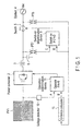
- a solar power system performs power conversion on direct-current power from a solar battery (PV) 1 by a power converter 2, such as an inverter, and supplies the converted power to an alternating-current power system 4.
- the solar power system comprises a switch 5 at a link point between the power converter 2 and the alternating-current power system 4.
- a reactor 3 is connected in series with a connection bus line between the power converter 2 and the switch 5, and a capacitor 6 is connected in parallel with the connection bus line.
- the solar power system is configured as follows.
- An operation control apparatus for a solar power system comprises: an alternating-current voltage detector (for example, PT) 7 which detects a voltage on a side of the power converter 2 of the switch 5 or more specifically between the capacitor 6 and the switch 5; an alternating-current voltage detector (for example, PT) 8 which detects a voltage on the side of the alternating-current power system 4 or more specifically between the alternating-current power system 4 and the switch 5; a switch-on determination device 9 which is input with a voltage C detected by the voltage detector 7 and a voltage D detected by the voltage detector 8, and supplies the switch 5 with a switch-on command if both voltages are approximately equal to each other; a criterion calculator 15 which obtains an operation criterion for the power converter 2, based on a moving average voltage detected by the voltage detector 8; a direct-current voltage detector 10 which detects a direct-current output voltage of the solar battery 1; and an operation determination device 11 which compares a direct-current output voltage A detected by the direct-current voltage detector 10 with an
- the moving average voltage is a value obtained by dividing, by time, a sum of instantaneous values of the voltage detected by the voltage detector 8 within a time band.
- FIG. 2 is a graph for explaining operation of the power converter 2, in which the vertical axis represents an input direct-current voltage of the power converter 2, as a direct-current output voltage of the solar battery 1, and the horizontal axis represents a system voltage of the alternating-current power system 4.
- a conventional solar power system needs to consider an upper-limit system voltage in setting up a minimum operation range of the power converter 2. Therefore, direct-current power from the solar battery 1 cannot be effectively used in a hatched range of FIG. 2 .
- a criterion B as a moving average voltage calculated by the criterion calculator 15 varies.
- the direct-current output voltage A of the solar battery 1 which is detected by the voltage detector 10 satisfies the condition A>B
- an operation command is supplied from the operation determination device 11 to the power converter 2.
- the power converter 2 then transits to an operating state and the switch 5 transits to a switch-on state.
- the direct-current power generated by the solar battery 1 is supplied to the alternating-current power system 4.
- the minimum-operation-input setting value (minimum-input-operation setting value) for the power converter 2 is varied in accordance with variation of the input voltage to the alternating-current power system 4.
- the power converter 2 is operated.
- the direct-current power generated from the solar battery 1 can be used even within the hatched range in FIG. 2 where the power cannot be used in the prior art. Therefore, the operation range widens and can improve total conversion efficiency throughout the solar power system. Another advantage is that the startup time of the power converter 2 is reduced.
- the invention obtains a moving average of the voltage of the alternating-current power system 4 described above.
- the rated voltage Vac of the alternating-current power system 4 is compensated for up to ⁇ 10%.
- the direct-current voltage E is improper unless the direct-current voltage E is at +10% to become E2.
- the solar battery 1 is +10%, the power converter 2 is not operated. Since variation of E is 0%, the solar battery 1 can operate. At -10%, operation can be achieved even with E1.
- the voltage of the alternating-current power system 4 compensates for +10% of Vac. Therefore, the power converter 2 does not operate unless the solar battery 1 supplies the voltage E2.
- the solar power system is designed to operate only when the power converter 2 can supply ⁇ 10% of Vac.
- the highest peak of the direct-current output voltage of the solar battery 1 is selected. At a voltage not smaller than the maximum output voltage of the solar battery 1, the power converter 2 can be operated.
- the invention considers variation of the system voltage of the alternating-current power system 4 as described above, to make the output voltage of the solar battery 1 be supplied to the side of the alternating-current power system 4.
- the solar battery 1 is started in view of the input voltage on the side of the alternating-current power system 4. Since the voltage of the alternating-current power system 4 varies, for example, an average value is obtained for waveforms for a number of cycles. For example, after checking an average value of 0% or +10%, the power converter 2 and the solar battery 1 are operated. Otherwise, the output voltage of the solar battery 1 may drop during actual operation after instantaneously exceeding the value. Therefore, for example, an average value is obtained at 10 and 100 Hz.
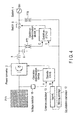
- FIG. 4 is a schematic diagram for explaining the second embodiment of the invention, which differs from the first embodiment in that a criterion calculator 15 is substituted with an equalization calculator 12 and a criterion calculator 13 and that an alternating-current power system 4 is of a single-phase type.
- the equalization calculator 12 obtains a single-phase alternating-current voltage detected by the voltage detector 8, for example, a moving average value Vac of a voltage within predetermined time.
- the criterion calculator 13 multiplies the moving average value Vac by a margin K (for example, 0.9 to 0.95), thereby to obtain an operation determination value B.
- a margin K for example, 0.9 to 0.95
- FIG. 5 is a schematic diagram for explaining the third embodiment of the invention, which differs from the first embodiment in that a criterion calculator 15 is substituted with an equalization calculator 12A and a criterion calculator 13A and that an alternating-current power system 4A is of a three-phase type.
- the equalization calculator 12A obtains a moving average value Vac of a three-phase alternating-current voltage detected by a voltage detector 8, for example, a three-phase voltage within predetermined time.
- the criterion calculator 13A multiplies the moving average value Vac by 1.35 and a margin K, to thereby obtain an operation determination value B.
- the configuration, operation, and effects are the same as those of the foregoing first embodiment, and descriptions thereof will therefore be omitted.
- the switch-on condition for the switch-on determination device 9 in the embodiments described above is that a switch-on command is supplied to the switch 5 when the detection value C of the voltage detector 7 provided between the capacitor 6 and the switch 5, and the detection value D of the voltage detector 8 provided between the switch 5 and the alternating-current power system 4 are approximately equal to each other, for example, when voltages, phases, and frequencies are approximately equal.
- the configuration may be arranged so as to experimentally obtain these values insofar as a condition of causing neither occurrence of current surge nor flow of overcurrent is satisfied when the switch 5 is switched on.
Abstract
Description
- The invention relates to an operation control apparatus for a power converter (power conditioner) in a solar power system.
- Patent Literature 1 discloses, as capability to effectively use generated power of a solar battery, an invention which suppresses a voltage rise at a power reception point connected to a power converter and to a power system, by making an ineffective phase advance current constantly flow while maintaining an effective current output.
-
Patent Literature 2 describes that an upper limit and a lower limit are provided for a link point in order that an output power of a dispersed power supply which is operated in cooperation with a power system is restricted from greatly hunting to maintain a constant link point voltage. When the link point voltage is within the limits, the link point voltage is restricted to be not greater than the upper limit, by continuing both controls (Normally, operation is performed to output the maximum power at a power ratio of 100%. Only when the link point voltage exceeds a limit, an effective power and an ineffective phase advance voltage are controlled to restrict the link point voltage). Only when the link point voltage is not greater than the lower limit, normal operation is recovered in which the maximum power at the power ratio of 100% is output. - Conventionally, there is a problem as follows in a system which converts direct-current power generated from a solar battery into alternating-current power by a power converter (power conditioner) and supplies the power to an alternating-current power system. In the power converter, power conversion is not performed unless a direct-current voltage from a solar power generation apparatus exceeds a minimum value (lower limit) when an alternating-current voltage is supplied to an alternating-current power system. The minimum value (lower limit) in this case is a value which is marginally tolerable. However, since voltage fluctuation occurs on the alternating-current side, effective use of the generated power from the solar battery is not achieved.
- When the direct-current voltage which is an input voltage of the power converter exceeds the minimum value (lower limit), the power converter is operated but the minimum value (lower limit) of the direct-current voltage is still fixed. Here, the minimum value (lower limit) of the direct-current voltage is determined to be the value when the solar power generation apparatus is under the worst conditions.
-
- Patent Literature 1: Japanese Patent No.
3528879 - Patent Literature 2: Japanese Patent No.
3407234 - Although the power converter can be operated in actual when the direct-current voltage as the output of the solar battery is low, the minimum value (lower limit) of the direct-current voltage is still fixed in the system, at present. As a result, even when the solar battery generates electricity, the generated power of the solar battery is wasted if the power converter is not operated.
- The invention has an object of providing an operation control apparatus in a solar power system, which can extend an operation range of a power converter and can effectively use generated power of a solar battery.
- To achieve the object, the invention corresponding to claim 1 provides an operation control apparatus for a solar power system that performs power conversion on direct-current power from a solar battery by a power converter, supplies an alternating-current power system with the power converted, and comprises a switch at a link point between the power converter and the alternating-current power system, the operation control apparatus characterized by comprising: a voltage detector that detects a voltage of the switch on a side of the power converter, and a voltage thereof on a side of the alternating-current power system; a switch-on determination device that is input with the voltages from the voltage detector on the sides of the power converter and the alternating-current power system, and supplies the switch with a switch-on command if both of the voltages are approximately equal to each other; a criterion calculator that obtains an operation criterion for the power converter, based on the voltage detected by the above voltage detector on the side of the alternating-current power system; a direct-current voltage detector that detects a direct-current output voltage of the solar battery; and an operation determination device that compares the direct-current output voltage detected by the direct-current voltage detector with the operation criterion obtained by the criterion calculator, and supplies the power converter with an operation command if the direct-current output voltage is greater than the operation criterion.
- To achieve the object, the invention corresponding to
claim 2 provides an operation control apparatus for a solar power system that converts direct-current power from a solar battery into a single-phase alternating-current power by a power converter, supplies an alternating-current power system with the single-phase alternating-current power converted, and comprises a switch at a link point between the power converter and the alternating-current power system, the operation control apparatus characterized by comprising: a voltage detector that detects a single-phase alternating-current voltage of the switch on a side of the power converter, and a voltage thereof on a side of the alternating-current power system; a switch-on determination device that is input with the voltages from the voltage detector on the sides of the power converter and the alternating-current power system, and supplies the switch with a switch-on command if both of the voltages are approximately equal to each other; a criterion calculator that obtains an operation criterion for the power converter, by multiplying, by a margin, a moving average voltage detected by the voltage detector on the side of the alternating-current power system; a direct-current voltage detector that detects a direct-current output voltage of the solar battery; and an operation determination device that compares the direct-current output voltage detected by the direct-current voltage detector with the operation criterion obtained by the criterion calculator, and supplies the power converter with an operation command if the direct-current output voltage is greater than the operation criterion. - To achieve the object, the invention corresponding to
claim 3 provides an operation control apparatus for a solar power system that converts direct-current power from a solar battery into a three-phase alternating-current power by a power converter, supplies an alternating-current power system with the three-phase alternating-current power converted, and comprises a switch at a link point between the power converter and the alternating-current power system, the operation control apparatus characterized by comprising: a voltage detector that detects a voltage of the switch on a side of the power converter, and a voltage thereof on a side of the alternating-current power system; a switch-on determination device that is input with the voltages from the voltage detector on the sides of the power converter and the alternating-current power system, and supplies the switch with a switch-on command if both of the voltages are approximately equal to each other; a criterion calculator that obtains an operation criterion for the power converter, by multiplying, by 1.35 and a margin, a moving average voltage detected by the voltage detector on the side of the alternating-current power system; a direct-current voltage detector that detects a direct-current output voltage of the solar battery; and an operation determination device that compares the direct-current output voltage detected by the direct-current voltage detector with the operation criterion obtained by the criterion calculator, and supplies the power converter with an operation command if the direct-current output voltage is greater than the operation criterion. - According to the invention as described above, the operation range of the power converter (inverter) can be extended by fluctuating a minimum-input-operation setting value for a solar battery in accordance with the voltage of an alternating-current power system.
- The operation range of the power converter is widened, and the power converter starts up in a shorter time. Therefore, the amount of total power generation can be increased.
-
-
FIG. 1 is a schematic diagram for explaining the first embodiment of the invention; -
FIG. 2 is a graph for explaining operation of a power converter ofFIG. 1 ; -
FIG. 3 is a graph for explaining operation ofFIG. 1 ; -
FIG. 4 is a schematic diagram for explaining the second embodiment of the invention; and -
FIG. 5 is a schematic diagram for explaining the second embodiment of the invention. - Mode for Carrying Out the Invention Hereinafter, embodiments of the invention will be described with reference to the drawings. In the invention, a solar power system performs power conversion on direct-current power from a solar battery (PV) 1 by a
power converter 2, such as an inverter, and supplies the converted power to an alternating-current power system 4. The solar power system comprises aswitch 5 at a link point between thepower converter 2 and the alternating-current power system 4. Areactor 3 is connected in series with a connection bus line between thepower converter 2 and theswitch 5, and a capacitor 6 is connected in parallel with the connection bus line. The solar power system is configured as follows. - An operation control apparatus for a solar power system comprises: an alternating-current voltage detector (for example, PT) 7 which detects a voltage on a side of the
power converter 2 of theswitch 5 or more specifically between the capacitor 6 and theswitch 5; an alternating-current voltage detector (for example, PT) 8 which detects a voltage on the side of the alternating-current power system 4 or more specifically between the alternating-current power system 4 and theswitch 5; a switch-ondetermination device 9 which is input with a voltage C detected by the voltage detector 7 and a voltage D detected by the voltage detector 8, and supplies theswitch 5 with a switch-on command if both voltages are approximately equal to each other; acriterion calculator 15 which obtains an operation criterion for thepower converter 2, based on a moving average voltage detected by the voltage detector 8; a direct-current voltage detector 10 which detects a direct-current output voltage of the solar battery 1; and anoperation determination device 11 which compares a direct-current output voltage A detected by the direct-current voltage detector 10 with an operation criterion B obtained by thecriterion calculator 15, and supplies thepower converter 2 with an operation command if the direct-current output voltage A is greater than the operation criterion B. - The moving average voltage is a value obtained by dividing, by time, a sum of instantaneous values of the voltage detected by the voltage detector 8 within a time band.
-
FIG. 2 is a graph for explaining operation of thepower converter 2, in which the vertical axis represents an input direct-current voltage of thepower converter 2, as a direct-current output voltage of the solar battery 1, and the horizontal axis represents a system voltage of the alternating-current power system 4. InFIG. 2 , a conventional solar power system needs to consider an upper-limit system voltage in setting up a minimum operation range of thepower converter 2. Therefore, direct-current power from the solar battery 1 cannot be effectively used in a hatched range ofFIG. 2 . - According to the embodiment described above, as the input voltage to the alternating-
current power system 4, which is detected by the voltage detector 8, varies, a criterion B as a moving average voltage calculated by thecriterion calculator 15 varies. When the direct-current output voltage A of the solar battery 1 which is detected by thevoltage detector 10 satisfies the condition A>B, an operation command is supplied from theoperation determination device 11 to thepower converter 2. Thepower converter 2 then transits to an operating state and theswitch 5 transits to a switch-on state. As a result, the direct-current power generated by the solar battery 1 is supplied to the alternating-current power system 4. - Thus, the minimum-operation-input setting value (minimum-input-operation setting value) for the
power converter 2 is varied in accordance with variation of the input voltage to the alternating-current power system 4. In accordance with the varied value, thepower converter 2 is operated. The direct-current power generated from the solar battery 1 can be used even within the hatched range inFIG. 2 where the power cannot be used in the prior art. Therefore, the operation range widens and can improve total conversion efficiency throughout the solar power system. Another advantage is that the startup time of thepower converter 2 is reduced. - The invention obtains a moving average of the voltage of the alternating-
current power system 4 described above. The rated voltage Vac of the alternating-current power system 4 is compensated for up to ±10%. For example, when the rated voltage Vac inFIG. 3 is at +10%, compensation cannot be achieved with a direct-current voltage E of the solar battery 1 inFIG. 3 . Therefore, the direct-current voltage E is improper unless the direct-current voltage E is at +10% to become E2. Unless the solar battery 1 is +10%, thepower converter 2 is not operated. Since variation of E is 0%, the solar battery 1 can operate. At -10%, operation can be achieved even with E1. - Conventionally, the voltage of the alternating-
current power system 4 compensates for +10% of Vac. Therefore, thepower converter 2 does not operate unless the solar battery 1 supplies the voltage E2. The solar power system is designed to operate only when thepower converter 2 can supply ±10% of Vac. The highest peak of the direct-current output voltage of the solar battery 1 is selected. At a voltage not smaller than the maximum output voltage of the solar battery 1, thepower converter 2 can be operated. - The invention considers variation of the system voltage of the alternating-
current power system 4 as described above, to make the output voltage of the solar battery 1 be supplied to the side of the alternating-current power system 4. The solar battery 1 is started in view of the input voltage on the side of the alternating-current power system 4. Since the voltage of the alternating-current power system 4 varies, for example, an average value is obtained for waveforms for a number of cycles. For example, after checking an average value of 0% or +10%, thepower converter 2 and the solar battery 1 are operated. Otherwise, the output voltage of the solar battery 1 may drop during actual operation after instantaneously exceeding the value. Therefore, for example, an average value is obtained at 10 and 100 Hz. -
FIG. 4 is a schematic diagram for explaining the second embodiment of the invention, which differs from the first embodiment in that acriterion calculator 15 is substituted with anequalization calculator 12 and acriterion calculator 13 and that an alternating-current power system 4 is of a single-phase type. Theequalization calculator 12 obtains a single-phase alternating-current voltage detected by the voltage detector 8, for example, a moving average value Vac of a voltage within predetermined time. Thecriterion calculator 13 multiplies the moving average value Vac by a margin K (for example, 0.9 to 0.95), thereby to obtain an operation determination value B. Except for the feature described above, the configuration, operation, and effects are the same as those of the foregoing first embodiment, and descriptions thereof will therefore be omitted. -
FIG. 5 is a schematic diagram for explaining the third embodiment of the invention, which differs from the first embodiment in that acriterion calculator 15 is substituted with anequalization calculator 12A and acriterion calculator 13A and that an alternating-current power system 4A is of a three-phase type. Theequalization calculator 12A obtains a moving average value Vac of a three-phase alternating-current voltage detected by a voltage detector 8, for example, a three-phase voltage within predetermined time. Thecriterion calculator 13A multiplies the moving average value Vac by 1.35 and a margin K, to thereby obtain an operation determination value B. Except for the feature described above, the configuration, operation, and effects are the same as those of the foregoing first embodiment, and descriptions thereof will therefore be omitted. - The foregoing embodiments have been described with reference to an example in which a
pure reactor 3 is provided between an output side of thepower converter 2 and theswitch 5. Even a reactor which has an insulating function, such as an inverter transformer, can be embodied in the same manner as in the foregoing embodiments. - The switch-on condition for the switch-on
determination device 9 in the embodiments described above is that a switch-on command is supplied to theswitch 5 when the detection value C of the voltage detector 7 provided between the capacitor 6 and theswitch 5, and the detection value D of the voltage detector 8 provided between theswitch 5 and the alternating-current power system 4 are approximately equal to each other, for example, when voltages, phases, and frequencies are approximately equal. However, the configuration may be arranged so as to experimentally obtain these values insofar as a condition of causing neither occurrence of current surge nor flow of overcurrent is satisfied when theswitch 5 is switched on. - 1... Solar battery, 2... power converter, 3... Reactor, 4... Alternating-current power system, 4A... Alternating-current voltage detector, 5... Switch, 6... Capacitor, 7... Alternating-current voltage detector, 8... Alternating-current voltage detector, 9... Switch-on determination device, 10... Direct-current voltage detector, 11... Operation determination device, 12... Equalization calculator, 12A... Equalization calculator, 13... Criterion calculator, 13A... Criterion calculator, 15... Criterion calculator
Claims (3)
- An operation control apparatus for a solar power system that performs power conversion on direct-current power from a solar battery by a power converter, supplies an alternating-current power system with the power converted, and comprises a switch at a link point between the power converter and the alternating-current power system, the operation control apparatus characterized by comprising:a voltage detector that detects a voltage of the switch on a side of the power converter, and a voltage thereof on a side of the alternating-current power system;a switch-on determination device that is input with the voltages from the voltage detector on the sides of the power converter and the alternating-current power system, and supplies the switch with a switch-on command if both of the voltages are approximately equal to each other;a criterion calculator that obtains an operation criterion for the power converter, based on the voltage detected by the above voltage detector on the side of the alternating-current power system;a direct-current voltage detector that detects a direct-current output voltage of the solar battery; andan operation determination device that compares the direct-current output voltage detected by the direct-current voltage detector with the operation criterion obtained by the criterion calculator, and supplies the power converter with an operation command if the direct-current output voltage is greater than the operation criterion.
- An operation control apparatus for a solar power system that converts direct-current power from a solar battery into a single-phase alternating-current power by a power converter, supplies an alternating-current power system with the single-phase alternating-current power converted, and comprises a switch at a link point between the power converter and the alternating-current power system, the operation control apparatus characterized by comprising:a voltage detector that detects a single-phase alternating-current voltage of the switch on a side of the power converter, and a voltage thereof on a side of the alternating-current power system;a switch-on determination device that is input with the voltages from the voltage detector on the sides of the power converter and the alternating-current power system, and supplies the switch with a switch-on command if both of the voltages are approximately equal to each other;a criterion calculator that obtains an operation criterion for the power converter, by multiplying, by a margin, a moving average voltage detected by the voltage detector on the side of the alternating-current power system;a direct-current voltage detector that detects a direct-current output voltage of the solar battery; andan operation determination device that compares the direct-current output voltage detected by the direct-current voltage detector with the operation criterion obtained by the criterion calculator, and supplies the power converter with an operation command if the direct-current output voltage is greater than the operation criterion.
- An operation control apparatus for a solar power system that converts direct-current power from a solar battery into a three-phase alternating-current power by a power converter, supplies an alternating-current power system with the three-phase alternating-current power converted, and comprises a switch at a link point between the power converter and the alternating-current power system, the operation control apparatus characterized by comprising:a voltage detector that detects a voltage of the switch on a side of the power converter, and a voltage thereof on a side of the alternating-current power system;a switch-on determination device that is input with the voltages from the voltage detector on the sides of the power converter and the alternating-current power system, and supplies the switch with a switch-on command if both of the voltages are approximately equal to each other;a criterion calculator that obtains an operation criterion for the power converter, by multiplying, by 1.35 and a margin, a moving average voltage detected by the voltage detector on the side of the alternating-current power system;a direct-current voltage detector that detects a direct-current output voltage of the solar battery; andan operation determination device that compares the direct-current output voltage detected by the direct-current voltage detector with the operation criterion obtained by the criterion calculator, and supplies the power converter with an operation command if the direct-current output voltage is greater than the operation criterion.
Applications Claiming Priority (1)
| Application Number | Priority Date | Filing Date | Title |
|---|---|---|---|
| PCT/JP2011/063056 WO2012169013A1 (en) | 2011-06-07 | 2011-06-07 | Operation control device for photovoltaic power generation system |
Publications (2)
| Publication Number | Publication Date |
|---|---|
| EP2720337A1 true EP2720337A1 (en) | 2014-04-16 |
| EP2720337A4 EP2720337A4 (en) | 2015-04-01 |
Family
ID=47295620
Family Applications (1)
| Application Number | Title | Priority Date | Filing Date |
|---|---|---|---|
| EP11867392.0A Ceased EP2720337A4 (en) | 2011-06-07 | 2011-06-07 | Operation control device for photovoltaic power generation system |
Country Status (5)
| Country | Link |
|---|---|
| US (1) | US10033189B2 (en) |
| EP (1) | EP2720337A4 (en) |
| JP (1) | JP5589141B2 (en) |
| CN (1) | CN103597694B (en) |
| WO (1) | WO2012169013A1 (en) |
Cited By (1)
| Publication number | Priority date | Publication date | Assignee | Title |
|---|---|---|---|---|
| EP3247018A4 (en) * | 2015-01-13 | 2018-10-24 | Toshiba Mitsubishi-Electric Industrial Systems Corporation | Control device for inverter |
Families Citing this family (7)
| Publication number | Priority date | Publication date | Assignee | Title |
|---|---|---|---|---|
| WO2017163625A1 (en) * | 2016-03-25 | 2017-09-28 | シャープ株式会社 | Power generation system, power conditioner, power control device, power control method, and power control program |
| TW201806289A (en) * | 2016-08-02 | 2018-02-16 | 台達電子工業股份有限公司 | Smart switch system and controlling method for switch box |
| JP6842953B2 (en) * | 2017-03-03 | 2021-03-17 | 田淵電機株式会社 | Power converter |
| WO2020204010A1 (en) * | 2019-03-29 | 2020-10-08 | 国立大学法人東北大学 | Electric power converting device, and electricity generating system |
| CN114556259B (en) * | 2019-12-12 | 2023-04-28 | 东芝三菱电机产业系统株式会社 | Power conversion device |
| CN112436557A (en) * | 2020-12-07 | 2021-03-02 | 阳光电源股份有限公司 | Medium-voltage photovoltaic grid-connected inverter system and photovoltaic power generation system |
| CN114204901B (en) * | 2021-11-29 | 2023-09-12 | 华为数字能源技术有限公司 | Photovoltaic system, inverter and bus voltage control method of inverter |
Citations (2)
| Publication number | Priority date | Publication date | Assignee | Title |
|---|---|---|---|---|
| JPH10229679A (en) * | 1997-02-18 | 1998-08-25 | Mitsubishi Electric Corp | Inverter device linked to system |
| US6239997B1 (en) * | 2000-09-01 | 2001-05-29 | Ford Motor Company | System for connecting and synchronizing a supplemental power source to a power grid |
Family Cites Families (11)
| Publication number | Priority date | Publication date | Assignee | Title |
|---|---|---|---|---|
| JPH08191573A (en) * | 1995-01-10 | 1996-07-23 | Sanyo Electric Co Ltd | Photovoltaic power generator |
| JP3407234B2 (en) | 1995-04-05 | 2003-05-19 | 富士電機株式会社 | Control method of distributed arrangement type power supply linked to power system |
| JP3528879B2 (en) | 1995-05-17 | 2004-05-24 | 株式会社安川電機 | Automatic voltage adjustment method for photovoltaic power converter |
| JP3234908B2 (en) * | 1996-08-05 | 2001-12-04 | シャープ株式会社 | Inverter device |
| US7158395B2 (en) * | 2003-05-02 | 2007-01-02 | Ballard Power Systems Corporation | Method and apparatus for tracking maximum power point for inverters, for example, in photovoltaic applications |
| CN1945920B (en) * | 2005-09-27 | 2012-09-05 | 歌美飒创新技术公司 | Method for operation of a converter system |
| EP1986306B1 (en) * | 2006-01-27 | 2014-05-14 | Sharp Kabushiki Kaisha | Power supply system |
| US8018748B2 (en) * | 2007-11-14 | 2011-09-13 | General Electric Company | Method and system to convert direct current (DC) to alternating current (AC) using a photovoltaic inverter |
| JP5198936B2 (en) * | 2008-05-19 | 2013-05-15 | 株式会社ダイヘン | Inverter starting device for starting inverter device of solar power generation system, method for starting inverter device, program for realizing inverter starting device, and recording medium recording this program |
| CN101789606B (en) * | 2010-03-12 | 2012-09-19 | 阳光电源股份有限公司 | Startup method for synchronization without insulating photovoltaic grid-connected inverters |
| JP5591641B2 (en) * | 2010-09-17 | 2014-09-17 | ローム株式会社 | Charging circuit, control IC thereof, and electronic device using the same |
-
2011
- 2011-06-07 JP JP2013519263A patent/JP5589141B2/en active Active
- 2011-06-07 WO PCT/JP2011/063056 patent/WO2012169013A1/en unknown
- 2011-06-07 CN CN201180071471.6A patent/CN103597694B/en active Active
- 2011-06-07 EP EP11867392.0A patent/EP2720337A4/en not_active Ceased
-
2013
- 2013-12-06 US US14/099,254 patent/US10033189B2/en active Active
Patent Citations (2)
| Publication number | Priority date | Publication date | Assignee | Title |
|---|---|---|---|---|
| JPH10229679A (en) * | 1997-02-18 | 1998-08-25 | Mitsubishi Electric Corp | Inverter device linked to system |
| US6239997B1 (en) * | 2000-09-01 | 2001-05-29 | Ford Motor Company | System for connecting and synchronizing a supplemental power source to a power grid |
Non-Patent Citations (1)
| Title |
|---|
| See also references of WO2012169013A1 * |
Cited By (1)
| Publication number | Priority date | Publication date | Assignee | Title |
|---|---|---|---|---|
| EP3247018A4 (en) * | 2015-01-13 | 2018-10-24 | Toshiba Mitsubishi-Electric Industrial Systems Corporation | Control device for inverter |
Also Published As
| Publication number | Publication date |
|---|---|
| JP5589141B2 (en) | 2014-09-10 |
| EP2720337A4 (en) | 2015-04-01 |
| US20140092657A1 (en) | 2014-04-03 |
| CN103597694A (en) | 2014-02-19 |
| CN103597694B (en) | 2016-07-06 |
| US10033189B2 (en) | 2018-07-24 |
| JPWO2012169013A1 (en) | 2015-02-23 |
| WO2012169013A1 (en) | 2012-12-13 |
Similar Documents
| Publication | Publication Date | Title |
|---|---|---|
| US10033189B2 (en) | Operation control apparatus for solar power system | |
| EP2950443B1 (en) | Variable frequency speed control system and method of the same | |
| US9515594B2 (en) | Wind turbine having improved overvoltage protection | |
| EP3069431B1 (en) | Uninterruptible power supply control | |
| JP6023259B2 (en) | Converter and operation method thereof | |
| JP5939069B2 (en) | Inverter | |
| JPWO2014147771A1 (en) | Solar power system | |
| US20150260161A1 (en) | Control device for voltage source converter and operating method thereof | |
| CN108702101B (en) | Power conversion device and method for operating the same | |
| EP3059653A1 (en) | Power conversion device and method for controlling same | |
| JP2013162699A (en) | Distributed power supply system and power conversion apparatus | |
| EP2892149A1 (en) | Thyristor activation device | |
| WO2016208432A1 (en) | Wind farm control device, wind farm, and wind farm control method | |
| JP5812503B1 (en) | Power supply system for photovoltaic power generation | |
| KR101318960B1 (en) | Uninterruptible power supply and method controlling thereof | |
| US10886744B2 (en) | Power conversion system, power supply system and power conversion device | |
| WO2018179714A1 (en) | Power conversion device and power conversion system | |
| KR102645329B1 (en) | Power system stabilization device through transmission limit control of HVDC system linked to wind power generation | |
| JP2019054641A (en) | Power conversion equipment | |
| JP2018170929A (en) | Electric power conversion system, and electric power conversion device | |
| KR20170104809A (en) | Apparatus and method for stabilizing voltage for direct current distribution system | |
| KR20160080719A (en) | Apparatus for controlling power configured to be connected to power system operating temporarily and method for controlling power | |
| US20140117755A1 (en) | Power system | |
| KR101566802B1 (en) | Charging system for charging DC link | |
| JP6343434B2 (en) | Power conversion device and power conversion method |
Legal Events
| Date | Code | Title | Description |
|---|---|---|---|
| PUAI | Public reference made under article 153(3) epc to a published international application that has entered the european phase |
Free format text: ORIGINAL CODE: 0009012 |
|
| 17P | Request for examination filed |
Effective date: 20131206 |
|
| AK | Designated contracting states |
Kind code of ref document: A1 Designated state(s): AL AT BE BG CH CY CZ DE DK EE ES FI FR GB GR HR HU IE IS IT LI LT LU LV MC MK MT NL NO PL PT RO RS SE SI SK SM TR |
|
| DAX | Request for extension of the european patent (deleted) | ||
| RA4 | Supplementary search report drawn up and despatched (corrected) |
Effective date: 20150303 |
|
| RIC1 | Information provided on ipc code assigned before grant |
Ipc: H02J 3/38 20060101AFI20150225BHEP Ipc: H02M 7/539 20060101ALI20150225BHEP |
|
| 17Q | First examination report despatched |
Effective date: 20160811 |
|
| STAA | Information on the status of an ep patent application or granted ep patent |
Free format text: STATUS: EXAMINATION IS IN PROGRESS |
|
| REG | Reference to a national code |
Ref country code: DE Ref legal event code: R003 |
|
| STAA | Information on the status of an ep patent application or granted ep patent |
Free format text: STATUS: THE APPLICATION HAS BEEN REFUSED |
|
| 18R | Application refused |
Effective date: 20200917 |