EP2720286A1 - Secondary battery - Google Patents
Secondary battery Download PDFInfo
- Publication number
- EP2720286A1 EP2720286A1 EP20130164368 EP13164368A EP2720286A1 EP 2720286 A1 EP2720286 A1 EP 2720286A1 EP 20130164368 EP20130164368 EP 20130164368 EP 13164368 A EP13164368 A EP 13164368A EP 2720286 A1 EP2720286 A1 EP 2720286A1
- Authority
- EP
- European Patent Office
- Prior art keywords
- secondary battery
- mounting portion
- battery according
- mounting
- extension
- Prior art date
- Legal status (The legal status is an assumption and is not a legal conclusion. Google has not performed a legal analysis and makes no representation as to the accuracy of the status listed.)
- Granted
Links
Images





Classifications
-
- H—ELECTRICITY
- H01—ELECTRIC ELEMENTS
- H01M—PROCESSES OR MEANS, e.g. BATTERIES, FOR THE DIRECT CONVERSION OF CHEMICAL ENERGY INTO ELECTRICAL ENERGY
- H01M50/00—Constructional details or processes of manufacture of the non-active parts of electrochemical cells other than fuel cells, e.g. hybrid cells
- H01M50/10—Primary casings; Jackets or wrappings
- H01M50/147—Lids or covers
-
- H—ELECTRICITY
- H01—ELECTRIC ELEMENTS
- H01M—PROCESSES OR MEANS, e.g. BATTERIES, FOR THE DIRECT CONVERSION OF CHEMICAL ENERGY INTO ELECTRICAL ENERGY
- H01M10/00—Secondary cells; Manufacture thereof
- H01M10/04—Construction or manufacture in general
- H01M10/0431—Cells with wound or folded electrodes
-
- H—ELECTRICITY
- H01—ELECTRIC ELEMENTS
- H01M—PROCESSES OR MEANS, e.g. BATTERIES, FOR THE DIRECT CONVERSION OF CHEMICAL ENERGY INTO ELECTRICAL ENERGY
- H01M50/00—Constructional details or processes of manufacture of the non-active parts of electrochemical cells other than fuel cells, e.g. hybrid cells
- H01M50/10—Primary casings; Jackets or wrappings
-
- H—ELECTRICITY
- H01—ELECTRIC ELEMENTS
- H01M—PROCESSES OR MEANS, e.g. BATTERIES, FOR THE DIRECT CONVERSION OF CHEMICAL ENERGY INTO ELECTRICAL ENERGY
- H01M50/00—Constructional details or processes of manufacture of the non-active parts of electrochemical cells other than fuel cells, e.g. hybrid cells
- H01M50/10—Primary casings; Jackets or wrappings
- H01M50/116—Primary casings; Jackets or wrappings characterised by the material
- H01M50/117—Inorganic material
- H01M50/119—Metals
-
- Y—GENERAL TAGGING OF NEW TECHNOLOGICAL DEVELOPMENTS; GENERAL TAGGING OF CROSS-SECTIONAL TECHNOLOGIES SPANNING OVER SEVERAL SECTIONS OF THE IPC; TECHNICAL SUBJECTS COVERED BY FORMER USPC CROSS-REFERENCE ART COLLECTIONS [XRACs] AND DIGESTS
- Y02—TECHNOLOGIES OR APPLICATIONS FOR MITIGATION OR ADAPTATION AGAINST CLIMATE CHANGE
- Y02E—REDUCTION OF GREENHOUSE GAS [GHG] EMISSIONS, RELATED TO ENERGY GENERATION, TRANSMISSION OR DISTRIBUTION
- Y02E60/00—Enabling technologies; Technologies with a potential or indirect contribution to GHG emissions mitigation
- Y02E60/10—Energy storage using batteries
Definitions
- An aspect of the present invention relates to a secondary battery.
- the present invention sets out to provide a secondary battery in which size is reduced.
- the invention also seeks to provide a secondary battery in which volume is reduced as compared with its capacity.
- FIG. 1 is a perspective view of a secondary battery according to an embodiment of the present invention.
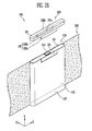
- FIG. 2A is a perspective view showing the secondary battery and a label according to the embodiment of the present invention.
- FIG. 2B is an exploded perspective view of the secondary battery of FIG. 1 .
- FIG. 3A is a perspective view of a cover according to the above embodiment of the present invention.
- FIG. 3B is a perspective view showing a lower portion of the cover of FIG. 3A .
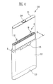
- FIG. 4 is a perspective view showing a battery case and an electrode assembly, shown in FIG. 1 .
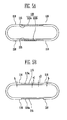
- FIG. 5A is a sectional view taken along line I-I of FIG. 2A .
- FIG. 5B is a sectional view taken along line II-II of FIG. 4 .
- FIG. 6 is a perspective view of a cover according to another embodiment of the present invention.
- FIG. 7 is a perspective view of a battery case according to the embodiment of the present invention.
- FIG. 8 is a sectional view showing a state in which the cover and the battery case are coupled together.
- FIG. 9 is a perspective view showing a cover and a battery case according to still another embodiment of the present invention.
- FIG. 10 is a perspective view showing a cover and a battery case according to still another embodiment of the present invention.
- FIG. 11 is a perspective view showing a lower portion of the cover of FIG. 10 .
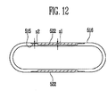
- FIG. 12 is a sectional view taken along line I-I of FIG. 2A according to still another embodiment of the present invention illustrating a stepped mounting portion.
- FIG. 1 is a perspective view of a secondary battery according to an embodiment of the present invention.
- FIG. 2A is a perspective view showing the secondary battery and a label according to the embodiment of the present invention.
- FIG. 2B is an exploded perspective view of the secondary battery of FIG. 1 .
- the secondary battery 100 includes a battery case 110 having a first surface 111, and a cover 120 that covers at least a portion of the first surface 111.
- the cover 120 includes an extension portion 122 that covers portions of a second surface 112 of the battery case 110, which is vertically connected to the first surface 111 of the battery case 110.
- the second surface 112 includes a mounting portion 115 on which the extension portion 122 is mounted, and the mounting portion 115 is recessed inward from a peripheral portion of the battery case 110.
- the secondary battery 100 further includes a label 130 that covers the second surface 112 of the secondary battery 100, and the label 130 covers the extension portion 122 of the cover 120.
- the label 130 is provided to surround the second surface 112 of the battery case 110.
- the extension portion 122 of the cover 120 is extended to cover the at least one portion of the second surface 112, and therefore is fixed together with the second surface 112 by the label 130.
- the extension portion 122 is inserted into the mounting portion 115 and the label 130 firmly fixes the extension portion 122 together with the second surface 112, so that it is possible to improve the coupling between the cover 120 and the battery case 110.
- the label 130 is composed of a sheet-shaped insulating member and an adhesive member formed on the insulating member.
- FIG. 3A is a perspective view of the cover according to this embodiment of the present invention.
- FIG. 3B is a perspective view showing a lower portion of the cover of FIG. 3A .
- FIG. 4 is a perspective view showing the battery case and an electrode assembly, shown in FIG. 1 .
- the cover 120 includes a base portion 121 provided in a shape corresponding to the first surface 111, and the extension portion 122 extended from the base portion 121 so as to cover respective portions of the second surface 112.
- the rib 122 includes first and second flanges 122a and 122b respectively extended from one side 121a and an opposite side 121b of the base portion 121.
- the first and second flanges 122a and 122b are provided in parallel with each other.
- the base portion 121 is provided in parallel with the first surface 111 so as to be mounted on the first surface 111 of the battery case 110, and the first and second flanges 122a and 122b are provided to extend perpendicular to the base portion 121 from the one side 121a and the other side 121b. More specifically, the first and second flanges 122a and 122b each extend from the base portion 121 so as to be parallel with the second surface 112 and perpendicular to the first surface 111. The first and second flanges 122a and 122b are provided so that outer surfaces of the first and second flanges 122a and 122b are parallel with those of the one and the other sides of the base portion 121. Thus, the outer surfaces of the base portion 121 and the first or second flange 122a and 122b at the side of the cover 120 can be provided on the approximately same plane without any protruded portion.
- the interval between the outer surfaces of the first and second flanges 122a and 122b corresponds to the maximum thickness of the battery case 120. Since the battery case 120 is inserted between the first and second flanges 122a and 122b, the interval between outer surfaces of the pair of mounting portions 115 in the battery case 120 is provided to correspond to the interval between inner surfaces of the first and second flanges 122a and 122b.
- the thickness s of each of the first and second flanges 122a and 122b is from 0.1 to 0.2mm in this embodiment. In a case where the thickness s of each of the first and second flanges 122a and 122b is less than 0.1 mm, it is difficult to manufacture the cover 120 through injection molding.
- each of the first and second flanges 122a and 122b exceeds 0.2mm, it is difficult to provide a space in which each of the first and second ribs 122a and 122b can be inserted into a respective mounting portion 115, and therefore, each of the first and second flanges 122a and 122b might in such a case protrude from the peripheral portion of the mounting portion 115. Further, the thickness of the portion at which each mounting portion 115 is provided in the second surface 112 would need to be relatively thin, and therefore, the strength of the battery case 110 may be lowered.
- the longitudinal length h parallel with the second surface in each of the first and second flanges 122a and 122b may be extended up to the longitudinal length of the battery case 110 from a minimum of 3mm.
- the longitudinal length h is less than 3mm, each of the first and second flanges 122a and 122b cannot be stably mounted on the mounting portion 115, and hence the cover 120 is easily detached from the battery case 110. Therefore, the cover 120 cannot be stably fixed to the battery case 110, In a case where the longitudinal length h exceeds the longitudinal length of the battery case 110, the entire length of the secondary battery 100 may be unnecessarily increased.
- an electrode assembly 10 and an electrolyte are provided in the battery case 110.
- the electrode assembly 10 may be manufactured by winding or stacking positive and negative electrode plates having different polarities and a separator interposed between the positive and negative electrode plates.
- the electrolyte facilitates the movement of current between the positive and negative electrode plates, and positive and negative electrode tabs 11 and 12 attached to the positive and negative electrode plates are electrically connected to the first surface 111 and an electrode terminal 114 provided to the first surface 111, respectively.
- the battery case 110 may be made of aluminum, steel or the like.
- the thickness of the battery case 110 may be from 0.2 to 0.5mm.
- the electrode terminal 114 is provided on the first surface 111, and the battery case 110 further includes a third surface 113 opposite to the first surface 111.
- the first and third surfaces 111 and 113 are provided in parallel with each other, and the second surface 112 is perpendicular to the first and third surfaces 111 and 113 so that the first and third surfaces 111 and 113 can be connected through the second surface 112.
- the cover 120 is provided only on the first surface 111 for convenience of illustration, the present invention is not limited thereto.
- the assembly may be provided with two covers which respectively cover the first and third surfaces 111 and 113.
- Each mounting portion 115 is provided in a shape corresponding to the flange 122 mounted on the mounting portion 115.
- the first and second flanges 122a and 122b are provided to have sizes corresponding to each other, and accordingly, the mounting portions 115 are also provided to have shapes corresponding to each other.
- the base portion 121 of the cover 120 is provided in a planar shape and may be further provided with a space formed in the inside of the base portion 121. That is, the base portion 121 may be further provided with a space formed in the opposite direction of the first and second flanges 122a and 122b, based on the surfaces of the base portion 121 to which the respective first and second flanges 122a and 122b are connected.
- the space may be used as a space in which a portion protruded from the first surface 111, a separate protection device or the like is accommodated.
- FIG. 5A is a sectional view taken along line I-I of FIG. 2A .
- FIG. 5B is a sectional view taken along line II-II of FIG. 4 .
- the outer surface of the second surface is recessed from a contiguous peripheral portion 116 of the mounting portion 115 so that the mounting portion 115 has a portion 115a recessed inward, whilst the inner surface of the second surface is flat.
- the mounting portion may be recessed relative to a portion of the second surface that is situated at some other location in a region adjacent the mounting portion. Consequently the thickness a1 of the mounting portion 115 is thinner than that b of the peripheral portion 116, and the depth a2 of the recessed portion 115a on the mounting portion 115 corresponds to that of each of the first and second flanges 122a and 122b.
- the recessed portion 115a on the mounting portion 115 can be offset by each of the first and second flanges 122a and 122b, and the mounting portion 115 having each of the first and second ribs 122a and 122b mounted thereon can form the same plane with the peripheral portion 116 of the mounting portion 115.
- the flanges are provided to the cover that covers the first surface, so that the cover can be firmly fixed to the battery case. Further, each flange is provided without any protruding portion by the mounting portion provided to the battery case, and thus it is possible to prevent an increase of volume regardless of the capacity of the secondary battery.
- FIGS. 6 to 10 Contents of these embodiments, except the following contents, are similar to those of the embodiment described with reference to FIGS. 1 to 5B , and therefore, their detailed descriptions will be omitted.
- FIG. 6 is a perspective view of a cover according to another embodiment of the present invention.
- FIG. 7 is a perspective view of a battery case according to this embodiment of the present invention.
- FIG. 8 is a sectional view showing a state in which the cover and the battery case are coupled together.
- the cover 220 that covers a first surface 211 includes a base portion 221 and an extension portion 222 extended from the base portion 221, and a second surface 212 of the battery case 210 is provided with a mounting portion 215 recessed inward so that the extension portion 222 is mounted on the mounting portion 215.
- the mounting portion 215 is provided to be recessed inward, so that after the extension portion 222 is mounted on the mounting portion 215, the thickness of the mounting portion 215 is approximately similar to that of a peripheral portion of the mounting portion 215.
- First and second fastening portions 223 and 216 are provided on the extension portion 222 and the mounting portion 215, respectively. That is, the first fastening portion 223 is provided in an inner surface of the extension portion 222, and the second fastening portion 216 fastened to the first fastening portion 223 is provided in an outer surface of the mounting portion 215.
- the first and second fastening portions 223 and 216 are fastened through groove-projection coupling although hook coupling is one of many suitable alternatives.
- FIG. 9 is a perspective view showing a cover and a battery case according to still another embodiment of the present invention.
- each mounting portion 315 provided in a second surface 312 of the battery case 310 is tapered. That is, the mounting portion 315 is provided in a tapered shape so that the width of the mounting portion 315 is gradually decreased in a direction distant from a first surface 311 of the battery case 310. Therefore, in each mounting portion 315, the width t2 of a portion adjacent to the first surface 311 is greater than that t1 of a portion most distant from the first surface 311.
- the cover 320 includes a base portion 321 corresponding to the first surface 311, and flanges 322 extended in the direction of the battery case 310 from both end portions of the base portion 321.
- the cover 320 may be coupled to the battery case 310 on the first surface 311 of the battery case 310.
- the flanges 322 each have a shape corresponding to the mounting portions 315. More specifically, each flange 322 has a tapered shape in which the width of an upper portion of the flange 322 is greater than that of a lower portion of the flange 322.
- each flange 322 when the cover 320 and the battery case 310 are coupled to each other, the most narrow width of each flange 322 is inserted in the narrowest width of a respective mounting portion 315, and accordingly, the flanges 322 can be easily accommodated in mounting portions 315. Further, the contact area between the flanges 322 and the mounting portion 315 is increased, so that it is possible to increase the coupling between the flanges 322 and the mounting portion 315.
- FIG. 10 is a perspective view showing a cover and a battery case according to still another embodiment of the present invention.
- FIG. 11 is a perspective view showing a lower portion of the cover of FIG. 10 .
- an upper portion of the battery case 410 may be inserted into the cover 420.
- the cover 420 coupled to the battery case 410 may include a base portion 421 opposite to a first surface 411 of the battery case 410, and a skirt 422 integrally provided along the outer circumferential surface of the base portion 421. That is, the cover 420 is provided with an accommodating portion 420a that is a space formed by the base portion 421 and the skirt 422, and at least one portion of the battery case 410 may be inserted into the accommodating portion 420a.
- a mounting portion 415 corresponding to the skirt 422 is provided at a portion connected to the first surface 411 from a second surface 412.
- the portion of the second surface 412 adjacent to the first surface 411 of the battery case 410 may be provided to be recessed from the portion at which the second surface is not adjacent to the first surface 411. Since the mounting portion 415 is provided in a shape corresponding to the skirt 422, the mounting portion 415 may be entirely provided at the upper portion of the battery case 410 adjacent to the first surface 411 of the battery case 410. Therefore, the thickness of the upper portion of the second surface 412 in the direction vertical to the first surface 411 is provided thinner than that of the lower portion of the second surface 412.
- FIG. 12 is a sectional view taken along line I-I of FIG. 2A according to still another embodiment of the present invention illustrating a stepped mounting portion.
- the outer surface of the second surface may be provided to be recessed from a peripheral portion 516 of the mounting portion 522 so that the mounting portion 522 has a stepped recessed portions 515 and 522, and the inner surface of the second surface may be provided to be flat. That is, the thickness of the mounting portion 522 may be provided thinner than the thickness of peripheral portion 516.
- the depth z2 of the stepped recess portion 515 is less than the depth z1 of the stepped recess portion 522, and the depth z1 and z2 of the recessed portions 522 and 515 may be provided to correspond to that of each of the first and second extension members 122a and 122b.
- the recessed portion 115a on the mounting portion 115 can be offset by each of the first and second extension members 122a and 122b, and the mounting portion 115 having each of the first and second extension members 122a and 122b mounted thereon can form the same plane with the peripheral portion 516 of the mounting portion 115.
Landscapes
- Chemical & Material Sciences (AREA)
- Chemical Kinetics & Catalysis (AREA)
- Electrochemistry (AREA)
- General Chemical & Material Sciences (AREA)
- Engineering & Computer Science (AREA)
- Manufacturing & Machinery (AREA)
- Inorganic Chemistry (AREA)
- Battery Mounting, Suspending (AREA)
- Sealing Battery Cases Or Jackets (AREA)
Abstract
Description
- An aspect of the present invention relates to a secondary battery.
- Recently, secondary batteries that use a non-aqueous liquid electrolyte have variously been used as power sources of portable electronic devices. As the portable electronic devices are used in various fields, demands on the secondary battery are rapidly increasing. A secondary battery can be reversibly charged/discharged many times, and thus is economically and environmentally efficient. Accordingly, the use of secondary batteries is encouraged.
- As a decrease in the size and weight of the electronic devices is required, a decrease in the size and weight of the secondary battery is also required. Accordingly, a variety of studies have been conducted to develop a secondary battery of which size and weight are reduced while maintaining safety and reliability without lowering the capacity of the secondary battery.
- The present invention sets out to provide a secondary battery in which size is reduced.
- The invention also seeks to provide a secondary battery in which volume is reduced as compared with its capacity.
- According to an aspect of the present invention, there is provided a secondary battery as set out in Claim 1.
- Preferred features of the invention are set out in Claims 2 to 15.
- The accompanying drawings, together with the description, illustrate embodiments of the present invention, and serve to explain the principles of the present invention.
-
FIG. 1 is a perspective view of a secondary battery according to an embodiment of the present invention. -
FIG. 2A is a perspective view showing the secondary battery and a label according to the embodiment of the present invention. -
FIG. 2B is an exploded perspective view of the secondary battery ofFIG. 1 . -
FIG. 3A is a perspective view of a cover according to the above embodiment of the present invention. -
FIG. 3B is a perspective view showing a lower portion of the cover ofFIG. 3A . -
FIG. 4 is a perspective view showing a battery case and an electrode assembly, shown inFIG. 1 . -
FIG. 5A is a sectional view taken along line I-I ofFIG. 2A . -
FIG. 5B is a sectional view taken along line II-II ofFIG. 4 . -
FIG. 6 is a perspective view of a cover according to another embodiment of the present invention. -
FIG. 7 is a perspective view of a battery case according to the embodiment of the present invention. -
FIG. 8 is a sectional view showing a state in which the cover and the battery case are coupled together. -
FIG. 9 is a perspective view showing a cover and a battery case according to still another embodiment of the present invention. -
FIG. 10 is a perspective view showing a cover and a battery case according to still another embodiment of the present invention. -
FIG. 11 is a perspective view showing a lower portion of the cover ofFIG. 10 . -
FIG. 12 is a sectional view taken along line I-I ofFIG. 2A according to still another embodiment of the present invention illustrating a stepped mounting portion. - In the following detailed description, only certain embodiments of the present invention have been shown and described, simply by way of illustration. As those skilled in the art would realize, the described embodiments may be modified in various different ways, all without departing from the scope of the present invention. Accordingly, the drawings and description are to be regarded as illustrative in nature and not restrictive. In addition, when an element is referred to as being "on" another element, it can be directly on the another element or be indirectly on the another element with one or more intervening elements interposed therebetween. Also, when an element is referred to as being "connected to" another element, it can be directly connected to the another element or be indirectly connected to the another element with one or more intervening elements interposed therebetween. Hereinafter, like reference numerals refer to like elements.
- Hereinafter, an embodiment of the present invention will be described in detail with reference to the accompanying drawings.
-
FIG. 1 is a perspective view of a secondary battery according to an embodiment of the present invention.FIG. 2A is a perspective view showing the secondary battery and a label according to the embodiment of the present invention.FIG. 2B is an exploded perspective view of the secondary battery ofFIG. 1 . - The
secondary battery 100 according to this embodiment includes abattery case 110 having afirst surface 111, and acover 120 that covers at least a portion of thefirst surface 111. Thecover 120 includes anextension portion 122 that covers portions of asecond surface 112 of thebattery case 110, which is vertically connected to thefirst surface 111 of thebattery case 110. Thesecond surface 112 includes amounting portion 115 on which theextension portion 122 is mounted, and themounting portion 115 is recessed inward from a peripheral portion of thebattery case 110. - The
secondary battery 100 further includes alabel 130 that covers thesecond surface 112 of thesecondary battery 100, and thelabel 130 covers theextension portion 122 of thecover 120. After thecover 120 is mounted on thefirst surface 111 of thebattery case 110, thelabel 130 is provided to surround thesecond surface 112 of thebattery case 110. In this case, theextension portion 122 of thecover 120 is extended to cover the at least one portion of thesecond surface 112, and therefore is fixed together with thesecond surface 112 by thelabel 130. Theextension portion 122 is inserted into themounting portion 115 and thelabel 130 firmly fixes theextension portion 122 together with thesecond surface 112, so that it is possible to improve the coupling between thecover 120 and thebattery case 110. Thelabel 130 is composed of a sheet-shaped insulating member and an adhesive member formed on the insulating member. Hereinafter, the configuration according to this embodiment will be described in detail with reference toFIGS. 1 to 2B . -
FIG. 3A is a perspective view of the cover according to this embodiment of the present invention.FIG. 3B is a perspective view showing a lower portion of the cover ofFIG. 3A .FIG. 4 is a perspective view showing the battery case and an electrode assembly, shown inFIG. 1 . - Referring to
FIGS. 3A and 3B , thecover 120 includes abase portion 121 provided in a shape corresponding to thefirst surface 111, and theextension portion 122 extended from thebase portion 121 so as to cover respective portions of thesecond surface 112. Therib 122 includes first andsecond flanges side 121a and anopposite side 121b of thebase portion 121. The first andsecond flanges - The
base portion 121 is provided in parallel with thefirst surface 111 so as to be mounted on thefirst surface 111 of thebattery case 110, and the first andsecond flanges base portion 121 from the oneside 121a and theother side 121b. More specifically, the first andsecond flanges base portion 121 so as to be parallel with thesecond surface 112 and perpendicular to thefirst surface 111. The first andsecond flanges second flanges base portion 121. Thus, the outer surfaces of thebase portion 121 and the first orsecond flange cover 120 can be provided on the approximately same plane without any protruded portion. - The interval between the outer surfaces of the first and
second flanges battery case 120. Since thebattery case 120 is inserted between the first andsecond flanges portions 115 in thebattery case 120 is provided to correspond to the interval between inner surfaces of the first andsecond flanges - The thickness s of each of the first and
second flanges second flanges cover 120 through injection molding. In a case where the thickness s of each of the first andsecond flanges second ribs portion 115, and therefore, each of the first andsecond flanges portion 115. Further, the thickness of the portion at which each mountingportion 115 is provided in thesecond surface 112 would need to be relatively thin, and therefore, the strength of thebattery case 110 may be lowered. - The longitudinal length h parallel with the second surface in each of the first and
second flanges battery case 110 from a minimum of 3mm. In a case where the longitudinal length h is less than 3mm, each of the first andsecond flanges portion 115, and hence thecover 120 is easily detached from thebattery case 110. Therefore, thecover 120 cannot be stably fixed to thebattery case 110, In a case where the longitudinal length h exceeds the longitudinal length of thebattery case 110, the entire length of thesecondary battery 100 may be unnecessarily increased. - Referring to
FIG. 4 , anelectrode assembly 10 and an electrolyte are provided in thebattery case 110. Theelectrode assembly 10 may be manufactured by winding or stacking positive and negative electrode plates having different polarities and a separator interposed between the positive and negative electrode plates. The electrolyte facilitates the movement of current between the positive and negative electrode plates, and positive andnegative electrode tabs 11 and 12 attached to the positive and negative electrode plates are electrically connected to thefirst surface 111 and anelectrode terminal 114 provided to thefirst surface 111, respectively. Thebattery case 110 may be made of aluminum, steel or the like. The thickness of thebattery case 110 may be from 0.2 to 0.5mm. - The
electrode terminal 114 is provided on thefirst surface 111, and thebattery case 110 further includes athird surface 113 opposite to thefirst surface 111. The first andthird surfaces second surface 112 is perpendicular to the first andthird surfaces third surfaces second surface 112. Although it has been described in this embodiment that thecover 120 is provided only on thefirst surface 111 for convenience of illustration, the present invention is not limited thereto. For example the assembly may be provided with two covers which respectively cover the first andthird surfaces - Each mounting
portion 115 is provided in a shape corresponding to theflange 122 mounted on the mountingportion 115. In this example, the first andsecond flanges portions 115 are also provided to have shapes corresponding to each other. - The
base portion 121 of thecover 120 is provided in a planar shape and may be further provided with a space formed in the inside of thebase portion 121. That is, thebase portion 121 may be further provided with a space formed in the opposite direction of the first andsecond flanges base portion 121 to which the respective first andsecond flanges first surface 111, a separate protection device or the like is accommodated. -
FIG. 5A is a sectional view taken along line I-I ofFIG. 2A .FIG. 5B is a sectional view taken along line II-II ofFIG. 4 . - Referring to
FIGS. 5A and 5B , the outer surface of the second surface is recessed from a contiguousperipheral portion 116 of the mountingportion 115 so that the mountingportion 115 has aportion 115a recessed inward, whilst the inner surface of the second surface is flat. In other embodiments the mounting portion may be recessed relative to a portion of the second surface that is situated at some other location in a region adjacent the mounting portion. Consequently the thickness a1 of the mountingportion 115 is thinner than that b of theperipheral portion 116, and the depth a2 of the recessedportion 115a on the mountingportion 115 corresponds to that of each of the first andsecond flanges portion 115a on the mountingportion 115 can be offset by each of the first andsecond flanges portion 115 having each of the first andsecond ribs peripheral portion 116 of the mountingportion 115. - In a secondary battery, it is very important that the size and weight of the secondary battery are reduced while maintaining the capacity of the secondary battery. Therefore, the safety and reliability of the secondary battery should be equally maintained while reducing the size and weight of the secondary battery. In the secondary battery according to this embodiment, the flanges are provided to the cover that covers the first surface, so that the cover can be firmly fixed to the battery case. Further, each flange is provided without any protruding portion by the mounting portion provided to the battery case, and thus it is possible to prevent an increase of volume regardless of the capacity of the secondary battery.
- Hereinafter, other embodiments of the present invention will be described with reference to
FIGS. 6 to 10 . Contents of these embodiments, except the following contents, are similar to those of the embodiment described with reference toFIGS. 1 to 5B , and therefore, their detailed descriptions will be omitted. -
FIG. 6 is a perspective view of a cover according to another embodiment of the present invention.FIG. 7 is a perspective view of a battery case according to this embodiment of the present invention.FIG. 8 is a sectional view showing a state in which the cover and the battery case are coupled together. - Referring to
FIGS. 6 to 8 , in the secondary battery according to this embodiment, thecover 220 that covers afirst surface 211 includes abase portion 221 and anextension portion 222 extended from thebase portion 221, and asecond surface 212 of thebattery case 210 is provided with a mountingportion 215 recessed inward so that theextension portion 222 is mounted on the mountingportion 215. The mountingportion 215 is provided to be recessed inward, so that after theextension portion 222 is mounted on the mountingportion 215, the thickness of the mountingportion 215 is approximately similar to that of a peripheral portion of the mountingportion 215. - First and
second fastening portions extension portion 222 and the mountingportion 215, respectively. That is, thefirst fastening portion 223 is provided in an inner surface of theextension portion 222, and thesecond fastening portion 216 fastened to thefirst fastening portion 223 is provided in an outer surface of the mountingportion 215. In this example, the first andsecond fastening portions battery case 210 is inserted between a pair offlanges 222 of theextension portion 222, thecover 220 is moved toward a lower portion of thebattery case 210, so that thebattery case 210 and thecover 220 can be coupled to each other. In this case, thefirst fastening portion 223 provided in theflanges 222 and thesecond fastening portion 216 provided in the mountingportion 215 can be easily fastened to each other, and thecover 220 can be firmly fixed to thebattery case 210. -
FIG. 9 is a perspective view showing a cover and a battery case according to still another embodiment of the present invention. - Referring to
FIG. 9 , a portion of each mountingportion 315 provided in asecond surface 312 of thebattery case 310 is tapered. That is, the mountingportion 315 is provided in a tapered shape so that the width of the mountingportion 315 is gradually decreased in a direction distant from afirst surface 311 of thebattery case 310. Therefore, in each mountingportion 315, the width t2 of a portion adjacent to thefirst surface 311 is greater than that t1 of a portion most distant from thefirst surface 311. - The
cover 320 includes abase portion 321 corresponding to thefirst surface 311, andflanges 322 extended in the direction of thebattery case 310 from both end portions of thebase portion 321. Thecover 320 may be coupled to thebattery case 310 on thefirst surface 311 of thebattery case 310. Theflanges 322 each have a shape corresponding to the mountingportions 315. More specifically, eachflange 322 has a tapered shape in which the width of an upper portion of theflange 322 is greater than that of a lower portion of theflange 322. Thus, when thecover 320 and thebattery case 310 are coupled to each other, the most narrow width of eachflange 322 is inserted in the narrowest width of a respective mountingportion 315, and accordingly, theflanges 322 can be easily accommodated in mountingportions 315. Further, the contact area between theflanges 322 and the mountingportion 315 is increased, so that it is possible to increase the coupling between theflanges 322 and the mountingportion 315. -
FIG. 10 is a perspective view showing a cover and a battery case according to still another embodiment of the present invention.FIG. 11 is a perspective view showing a lower portion of the cover ofFIG. 10 . - In the
battery case 410 according to this embodiment, an upper portion of thebattery case 410 may be inserted into thecover 420. Thecover 420 coupled to thebattery case 410 may include abase portion 421 opposite to afirst surface 411 of thebattery case 410, and askirt 422 integrally provided along the outer circumferential surface of thebase portion 421. That is, thecover 420 is provided with anaccommodating portion 420a that is a space formed by thebase portion 421 and theskirt 422, and at least one portion of thebattery case 410 may be inserted into theaccommodating portion 420a. - A mounting
portion 415 corresponding to theskirt 422 is provided at a portion connected to thefirst surface 411 from asecond surface 412. The portion of thesecond surface 412 adjacent to thefirst surface 411 of thebattery case 410 may be provided to be recessed from the portion at which the second surface is not adjacent to thefirst surface 411. Since the mountingportion 415 is provided in a shape corresponding to theskirt 422, the mountingportion 415 may be entirely provided at the upper portion of thebattery case 410 adjacent to thefirst surface 411 of thebattery case 410. Therefore, the thickness of the upper portion of thesecond surface 412 in the direction vertical to thefirst surface 411 is provided thinner than that of the lower portion of thesecond surface 412. -
FIG. 12 is a sectional view taken along line I-I ofFIG. 2A according to still another embodiment of the present invention illustrating a stepped mounting portion. Referring toFIG. 12 , the outer surface of the second surface may be provided to be recessed from aperipheral portion 516 of the mountingportion 522 so that the mountingportion 522 has a stepped recessedportions portion 522 may be provided thinner than the thickness ofperipheral portion 516. Further, the depth z2 of the steppedrecess portion 515 is less than the depth z1 of the steppedrecess portion 522, and the depth z1 and z2 of the recessedportions second extension members portion 115a on the mountingportion 115 can be offset by each of the first andsecond extension members portion 115 having each of the first andsecond extension members peripheral portion 516 of the mountingportion 115. - While the present invention has been described in connection with certain embodiments, it is to be understood that the invention is not limited to the disclosed embodiments, but, on the contrary, is intended to cover various modifications and equivalent arrangements included within the scope of the appended claims, and equivalents thereof.
Claims (15)
- A secondary battery (100) comprising:a case (110) having a first surface (111) and a second surface (112); anda cover (120) that is fitted to the case (110) and includes a base portion (121) that covers at least one portion of the first surface (111);wherein;the second surface (112) is provided with a mounting portion (115);the mounting portion (115) is recessed inwardly relative to a peripheral portion (116) of the second surface (112) that is situated in a region adjacent the mounting portion (115); andthe cover (120) further includes at least one extension portion (122) that extends from the base portion (121) and is accommodated within the mounting portion (115)
- A secondary battery according to claim 1, wherein the base portion (121) has a shape corresponding to the first surface (111).
- A secondary battery according to claim 1 or 2, wherein the extension portion (122) includes a flange.
- A secondary battery according to any preceding claim, wherein a wall thickness of the mounting portion (115) is less than a wall thickness of the peripheral portion (116).
- A secondary battery according to claim 4, wherein an inner surface portion of the case (120) overlaps both the mounting portion (115) and the peripheral portion (116), the said inner surface portion being flat.
- A secondary battery according to any preceding claim, wherein an external surface of the extension portion (122) is flush with an external surface of the peripheral portion (116).
- A secondary battery according to any preceding claim, wherein the mounting portion (115) has a peripheral shape corresponding to that of the extension portion (122).
- A secondary battery according to any preceding claim, further including a label (130) that at least partly covers the second surface (112) of the case (110) and the extension portion (122).
- A secondary battery according to any preceding claim, wherein a first fastening portion (223) is provided on an inner surface of the extension portion (222) and a second fastening portion (216) is provided on an outer surface of the mounting portion (215), the said first and second fastening portions (223, 216) being connectable together in order to secure the extension portion (222) within the mounting portion (225).
- A secondary battery according to any preceding claim, wherein the extension portion (122) is integrally provided on an outer circumferential surface of the base portion (121).
- A secondary battery according to any preceding claim, wherein the mounting portion (315) has a tapered peripheral shape, in which the width of the mounting portion (315) decreases in a direction extending away from the said first surface (311).
- A secondary battery according to one of claims 1 to 10, wherein the extension portion (422) takes the form of a skirt depending from the base portion (421) so as to define a space (420a) and the mounting portion (415) is inserted into the space (420a).
- A secondary battery according to claim 12, wherein the mounting portion (415) is defined by a portion of the second surface (412) adjacent the first surface (411) that is recessed from a portion of the second surface that is not adjacent to the first surface (411).
- A secondary battery according to one of claims 1 to 10, wherein the extension portion includes two substantially parallel flanges (122), each said flange (122) being situated on a respective one of first and second mutually opposite sides (121a, 121b) of the base portion (121); and the second surface (112) is provided with two mounting portions (115), each said flange (122) being mounted on a respective one of the said mounting portions (115).
- A secondary battery according to claim 14, wherein the interval between respective outer surfaces of the extension portions (115) corresponds to a maximum thickness of the case (110).
Applications Claiming Priority (2)
| Application Number | Priority Date | Filing Date | Title |
|---|---|---|---|
| US201261711712P | 2012-10-09 | 2012-10-09 | |
| US13/803,369 US20140099532A1 (en) | 2012-10-09 | 2013-03-14 | Secondary battery |
Publications (2)
| Publication Number | Publication Date |
|---|---|
| EP2720286A1 true EP2720286A1 (en) | 2014-04-16 |
| EP2720286B1 EP2720286B1 (en) | 2017-11-22 |
Family
ID=48128191
Family Applications (1)
| Application Number | Title | Priority Date | Filing Date |
|---|---|---|---|
| EP13164368.6A Active EP2720286B1 (en) | 2012-10-09 | 2013-04-18 | Secondary battery |
Country Status (3)
| Country | Link |
|---|---|
| US (1) | US20140099532A1 (en) |
| EP (1) | EP2720286B1 (en) |
| KR (1) | KR20140045866A (en) |
Families Citing this family (4)
| Publication number | Priority date | Publication date | Assignee | Title |
|---|---|---|---|---|
| TWI531104B (en) * | 2013-09-25 | 2016-04-21 | 原瑞電池科技股份有限公司 | Battery module |
| TWI514644B (en) * | 2013-09-25 | 2015-12-21 | Uer Technology Corp | Battery module |
| USD747264S1 (en) * | 2014-01-30 | 2016-01-12 | Nikon Corporation | Battery |
| CN104183798B (en) * | 2014-08-06 | 2016-09-07 | 江苏华东锂电技术研究院有限公司 | Battery cell and battery pack |
Citations (4)
| Publication number | Priority date | Publication date | Assignee | Title |
|---|---|---|---|---|
| FR1218634A (en) * | 1958-12-19 | 1960-05-11 | Accumulateurs Fixes | Tray for electric accumulators and similar uses |
| EP2058877A1 (en) * | 2007-11-12 | 2009-05-13 | Samsung SDI Co., Ltd. | Battery Pack |
| US20090246621A1 (en) * | 2008-04-01 | 2009-10-01 | Sony Corporation | Battery pack and battery-pack exterior casing |
| EP2405508A1 (en) * | 2010-07-09 | 2012-01-11 | Samsung SDI Co., Ltd. | Battery pack |
Family Cites Families (1)
| Publication number | Priority date | Publication date | Assignee | Title |
|---|---|---|---|---|
| EP1714334B1 (en) * | 2004-01-28 | 2017-11-08 | Lg Chem, Ltd. | Secondary battery of assemble-type structure |
-
2013
- 2013-03-14 US US13/803,369 patent/US20140099532A1/en not_active Abandoned
- 2013-04-18 EP EP13164368.6A patent/EP2720286B1/en active Active
- 2013-07-05 KR KR1020130078947A patent/KR20140045866A/en not_active Ceased
Patent Citations (4)
| Publication number | Priority date | Publication date | Assignee | Title |
|---|---|---|---|---|
| FR1218634A (en) * | 1958-12-19 | 1960-05-11 | Accumulateurs Fixes | Tray for electric accumulators and similar uses |
| EP2058877A1 (en) * | 2007-11-12 | 2009-05-13 | Samsung SDI Co., Ltd. | Battery Pack |
| US20090246621A1 (en) * | 2008-04-01 | 2009-10-01 | Sony Corporation | Battery pack and battery-pack exterior casing |
| EP2405508A1 (en) * | 2010-07-09 | 2012-01-11 | Samsung SDI Co., Ltd. | Battery pack |
Also Published As
| Publication number | Publication date |
|---|---|
| US20140099532A1 (en) | 2014-04-10 |
| EP2720286B1 (en) | 2017-11-22 |
| KR20140045866A (en) | 2014-04-17 |
Similar Documents
| Publication | Publication Date | Title |
|---|---|---|
| EP2333877B1 (en) | Secondary battery | |
| EP2763208B1 (en) | Battery pack | |
| US8795873B2 (en) | Case for battery pack and battery pack having the same | |
| EP2395593A3 (en) | Secondary battery | |
| EP2637232B1 (en) | Secondary battery | |
| US9431636B2 (en) | Rechargeable battery | |
| KR20160107061A (en) | Rechargeable battery having upper insulator member | |
| EP2720286B1 (en) | Secondary battery | |
| US20150340733A1 (en) | Battery cell of novel structure with improved safety | |
| EP4235892A2 (en) | Connection member and rechargeable battery | |
| CN104659373A (en) | Secondary battery | |
| JP2014056807A (en) | Battery pack | |
| US20140120379A1 (en) | Battery pack | |
| US20150064504A1 (en) | Battery module having connecting tab | |
| US10333115B2 (en) | Tray for curved surface-structured battery cell | |
| US20150093622A1 (en) | Battery case | |
| CN112909394B (en) | battery pack | |
| CN105336900B (en) | A kind of battery spacer ring, battery core protection component and power battery | |
| US20100330412A1 (en) | Secondary battery | |
| KR20140004391A (en) | Battery pack and case | |
| EP2894691B1 (en) | Secondary battery | |
| CN105098130B (en) | Secondary battery | |
| US9515308B2 (en) | Battery pack | |
| KR20160045439A (en) | Variable battery and portable electronic equipment comprising the same |
Legal Events
| Date | Code | Title | Description |
|---|---|---|---|
| PUAI | Public reference made under article 153(3) epc to a published international application that has entered the european phase |
Free format text: ORIGINAL CODE: 0009012 |
|
| AK | Designated contracting states |
Kind code of ref document: A1 Designated state(s): AL AT BE BG CH CY CZ DE DK EE ES FI FR GB GR HR HU IE IS IT LI LT LU LV MC MK MT NL NO PL PT RO RS SE SI SK SM TR |
|
| AX | Request for extension of the european patent |
Extension state: BA ME |
|
| 17P | Request for examination filed |
Effective date: 20141014 |
|
| RBV | Designated contracting states (corrected) |
Designated state(s): AL AT BE BG CH CY CZ DE DK EE ES FI FR GB GR HR HU IE IS IT LI LT LU LV MC MK MT NL NO PL PT RO RS SE SI SK SM TR |
|
| 17Q | First examination report despatched |
Effective date: 20150312 |
|
| GRAP | Despatch of communication of intention to grant a patent |
Free format text: ORIGINAL CODE: EPIDOSNIGR1 |
|
| RIC1 | Information provided on ipc code assigned before grant |
Ipc: H01M 2/04 20060101AFI20170428BHEP Ipc: H01M 2/02 20060101ALI20170428BHEP |
|
| INTG | Intention to grant announced |
Effective date: 20170601 |
|
| GRAS | Grant fee paid |
Free format text: ORIGINAL CODE: EPIDOSNIGR3 |
|
| GRAA | (expected) grant |
Free format text: ORIGINAL CODE: 0009210 |
|
| AK | Designated contracting states |
Kind code of ref document: B1 Designated state(s): AL AT BE BG CH CY CZ DE DK EE ES FI FR GB GR HR HU IE IS IT LI LT LU LV MC MK MT NL NO PL PT RO RS SE SI SK SM TR |
|
| REG | Reference to a national code |
Ref country code: GB Ref legal event code: FG4D |
|
| REG | Reference to a national code |
Ref country code: CH Ref legal event code: EP |
|
| REG | Reference to a national code |
Ref country code: IE Ref legal event code: FG4D |
|
| REG | Reference to a national code |
Ref country code: AT Ref legal event code: REF Ref document number: 949167 Country of ref document: AT Kind code of ref document: T Effective date: 20171215 |
|
| REG | Reference to a national code |
Ref country code: DE Ref legal event code: R096 Ref document number: 602013029677 Country of ref document: DE |
|
| REG | Reference to a national code |
Ref country code: FR Ref legal event code: PLFP Year of fee payment: 6 |
|
| REG | Reference to a national code |
Ref country code: NL Ref legal event code: MP Effective date: 20171122 |
|
| REG | Reference to a national code |
Ref country code: LT Ref legal event code: MG4D |
|
| REG | Reference to a national code |
Ref country code: AT Ref legal event code: MK05 Ref document number: 949167 Country of ref document: AT Kind code of ref document: T Effective date: 20171122 |
|
| PG25 | Lapsed in a contracting state [announced via postgrant information from national office to epo] |
Ref country code: FI Free format text: LAPSE BECAUSE OF FAILURE TO SUBMIT A TRANSLATION OF THE DESCRIPTION OR TO PAY THE FEE WITHIN THE PRESCRIBED TIME-LIMIT Effective date: 20171122 Ref country code: NL Free format text: LAPSE BECAUSE OF FAILURE TO SUBMIT A TRANSLATION OF THE DESCRIPTION OR TO PAY THE FEE WITHIN THE PRESCRIBED TIME-LIMIT Effective date: 20171122 Ref country code: LT Free format text: LAPSE BECAUSE OF FAILURE TO SUBMIT A TRANSLATION OF THE DESCRIPTION OR TO PAY THE FEE WITHIN THE PRESCRIBED TIME-LIMIT Effective date: 20171122 Ref country code: NO Free format text: LAPSE BECAUSE OF FAILURE TO SUBMIT A TRANSLATION OF THE DESCRIPTION OR TO PAY THE FEE WITHIN THE PRESCRIBED TIME-LIMIT Effective date: 20180222 Ref country code: SE Free format text: LAPSE BECAUSE OF FAILURE TO SUBMIT A TRANSLATION OF THE DESCRIPTION OR TO PAY THE FEE WITHIN THE PRESCRIBED TIME-LIMIT Effective date: 20171122 Ref country code: ES Free format text: LAPSE BECAUSE OF FAILURE TO SUBMIT A TRANSLATION OF THE DESCRIPTION OR TO PAY THE FEE WITHIN THE PRESCRIBED TIME-LIMIT Effective date: 20171122 |
|
| PG25 | Lapsed in a contracting state [announced via postgrant information from national office to epo] |
Ref country code: LV Free format text: LAPSE BECAUSE OF FAILURE TO SUBMIT A TRANSLATION OF THE DESCRIPTION OR TO PAY THE FEE WITHIN THE PRESCRIBED TIME-LIMIT Effective date: 20171122 Ref country code: AT Free format text: LAPSE BECAUSE OF FAILURE TO SUBMIT A TRANSLATION OF THE DESCRIPTION OR TO PAY THE FEE WITHIN THE PRESCRIBED TIME-LIMIT Effective date: 20171122 Ref country code: RS Free format text: LAPSE BECAUSE OF FAILURE TO SUBMIT A TRANSLATION OF THE DESCRIPTION OR TO PAY THE FEE WITHIN THE PRESCRIBED TIME-LIMIT Effective date: 20171122 Ref country code: GR Free format text: LAPSE BECAUSE OF FAILURE TO SUBMIT A TRANSLATION OF THE DESCRIPTION OR TO PAY THE FEE WITHIN THE PRESCRIBED TIME-LIMIT Effective date: 20180223 Ref country code: BG Free format text: LAPSE BECAUSE OF FAILURE TO SUBMIT A TRANSLATION OF THE DESCRIPTION OR TO PAY THE FEE WITHIN THE PRESCRIBED TIME-LIMIT Effective date: 20180222 Ref country code: HR Free format text: LAPSE BECAUSE OF FAILURE TO SUBMIT A TRANSLATION OF THE DESCRIPTION OR TO PAY THE FEE WITHIN THE PRESCRIBED TIME-LIMIT Effective date: 20171122 |
|
| PG25 | Lapsed in a contracting state [announced via postgrant information from national office to epo] |
Ref country code: EE Free format text: LAPSE BECAUSE OF FAILURE TO SUBMIT A TRANSLATION OF THE DESCRIPTION OR TO PAY THE FEE WITHIN THE PRESCRIBED TIME-LIMIT Effective date: 20171122 Ref country code: DK Free format text: LAPSE BECAUSE OF FAILURE TO SUBMIT A TRANSLATION OF THE DESCRIPTION OR TO PAY THE FEE WITHIN THE PRESCRIBED TIME-LIMIT Effective date: 20171122 Ref country code: CY Free format text: LAPSE BECAUSE OF FAILURE TO SUBMIT A TRANSLATION OF THE DESCRIPTION OR TO PAY THE FEE WITHIN THE PRESCRIBED TIME-LIMIT Effective date: 20171122 Ref country code: CZ Free format text: LAPSE BECAUSE OF FAILURE TO SUBMIT A TRANSLATION OF THE DESCRIPTION OR TO PAY THE FEE WITHIN THE PRESCRIBED TIME-LIMIT Effective date: 20171122 Ref country code: SK Free format text: LAPSE BECAUSE OF FAILURE TO SUBMIT A TRANSLATION OF THE DESCRIPTION OR TO PAY THE FEE WITHIN THE PRESCRIBED TIME-LIMIT Effective date: 20171122 |
|
| REG | Reference to a national code |
Ref country code: DE Ref legal event code: R097 Ref document number: 602013029677 Country of ref document: DE |
|
| PG25 | Lapsed in a contracting state [announced via postgrant information from national office to epo] |
Ref country code: PL Free format text: LAPSE BECAUSE OF FAILURE TO SUBMIT A TRANSLATION OF THE DESCRIPTION OR TO PAY THE FEE WITHIN THE PRESCRIBED TIME-LIMIT Effective date: 20171122 Ref country code: SM Free format text: LAPSE BECAUSE OF FAILURE TO SUBMIT A TRANSLATION OF THE DESCRIPTION OR TO PAY THE FEE WITHIN THE PRESCRIBED TIME-LIMIT Effective date: 20171122 Ref country code: IT Free format text: LAPSE BECAUSE OF FAILURE TO SUBMIT A TRANSLATION OF THE DESCRIPTION OR TO PAY THE FEE WITHIN THE PRESCRIBED TIME-LIMIT Effective date: 20171122 Ref country code: RO Free format text: LAPSE BECAUSE OF FAILURE TO SUBMIT A TRANSLATION OF THE DESCRIPTION OR TO PAY THE FEE WITHIN THE PRESCRIBED TIME-LIMIT Effective date: 20171122 |
|
| PLBE | No opposition filed within time limit |
Free format text: ORIGINAL CODE: 0009261 |
|
| STAA | Information on the status of an ep patent application or granted ep patent |
Free format text: STATUS: NO OPPOSITION FILED WITHIN TIME LIMIT |
|
| 26N | No opposition filed |
Effective date: 20180823 |
|
| PG25 | Lapsed in a contracting state [announced via postgrant information from national office to epo] |
Ref country code: MC Free format text: LAPSE BECAUSE OF FAILURE TO SUBMIT A TRANSLATION OF THE DESCRIPTION OR TO PAY THE FEE WITHIN THE PRESCRIBED TIME-LIMIT Effective date: 20171122 Ref country code: SI Free format text: LAPSE BECAUSE OF FAILURE TO SUBMIT A TRANSLATION OF THE DESCRIPTION OR TO PAY THE FEE WITHIN THE PRESCRIBED TIME-LIMIT Effective date: 20171122 |
|
| REG | Reference to a national code |
Ref country code: CH Ref legal event code: PL |
|
| REG | Reference to a national code |
Ref country code: BE Ref legal event code: MM Effective date: 20180430 |
|
| REG | Reference to a national code |
Ref country code: IE Ref legal event code: MM4A |
|
| PG25 | Lapsed in a contracting state [announced via postgrant information from national office to epo] |
Ref country code: LU Free format text: LAPSE BECAUSE OF NON-PAYMENT OF DUE FEES Effective date: 20180418 |
|
| PG25 | Lapsed in a contracting state [announced via postgrant information from national office to epo] |
Ref country code: BE Free format text: LAPSE BECAUSE OF NON-PAYMENT OF DUE FEES Effective date: 20180430 Ref country code: LI Free format text: LAPSE BECAUSE OF NON-PAYMENT OF DUE FEES Effective date: 20180430 Ref country code: CH Free format text: LAPSE BECAUSE OF NON-PAYMENT OF DUE FEES Effective date: 20180430 |
|
| PG25 | Lapsed in a contracting state [announced via postgrant information from national office to epo] |
Ref country code: IE Free format text: LAPSE BECAUSE OF NON-PAYMENT OF DUE FEES Effective date: 20180418 |
|
| PG25 | Lapsed in a contracting state [announced via postgrant information from national office to epo] |
Ref country code: MT Free format text: LAPSE BECAUSE OF NON-PAYMENT OF DUE FEES Effective date: 20180418 |
|
| PG25 | Lapsed in a contracting state [announced via postgrant information from national office to epo] |
Ref country code: TR Free format text: LAPSE BECAUSE OF FAILURE TO SUBMIT A TRANSLATION OF THE DESCRIPTION OR TO PAY THE FEE WITHIN THE PRESCRIBED TIME-LIMIT Effective date: 20171122 |
|
| PG25 | Lapsed in a contracting state [announced via postgrant information from national office to epo] |
Ref country code: PT Free format text: LAPSE BECAUSE OF FAILURE TO SUBMIT A TRANSLATION OF THE DESCRIPTION OR TO PAY THE FEE WITHIN THE PRESCRIBED TIME-LIMIT Effective date: 20171122 Ref country code: HU Free format text: LAPSE BECAUSE OF FAILURE TO SUBMIT A TRANSLATION OF THE DESCRIPTION OR TO PAY THE FEE WITHIN THE PRESCRIBED TIME-LIMIT; INVALID AB INITIO Effective date: 20130418 |
|
| PG25 | Lapsed in a contracting state [announced via postgrant information from national office to epo] |
Ref country code: MK Free format text: LAPSE BECAUSE OF NON-PAYMENT OF DUE FEES Effective date: 20171122 |
|
| PG25 | Lapsed in a contracting state [announced via postgrant information from national office to epo] |
Ref country code: AL Free format text: LAPSE BECAUSE OF FAILURE TO SUBMIT A TRANSLATION OF THE DESCRIPTION OR TO PAY THE FEE WITHIN THE PRESCRIBED TIME-LIMIT Effective date: 20171122 Ref country code: IS Free format text: LAPSE BECAUSE OF FAILURE TO SUBMIT A TRANSLATION OF THE DESCRIPTION OR TO PAY THE FEE WITHIN THE PRESCRIBED TIME-LIMIT Effective date: 20180322 |
|
| REG | Reference to a national code |
Ref country code: DE Ref legal event code: R079 Ref document number: 602013029677 Country of ref document: DE Free format text: PREVIOUS MAIN CLASS: H01M0002040000 Ipc: H01M0050147000 |
|
| P01 | Opt-out of the competence of the unified patent court (upc) registered |
Effective date: 20230528 |
|
| PGFP | Annual fee paid to national office [announced via postgrant information from national office to epo] |
Ref country code: DE Payment date: 20250408 Year of fee payment: 13 |
|
| PGFP | Annual fee paid to national office [announced via postgrant information from national office to epo] |
Ref country code: GB Payment date: 20250403 Year of fee payment: 13 |
|
| PGFP | Annual fee paid to national office [announced via postgrant information from national office to epo] |
Ref country code: FR Payment date: 20250409 Year of fee payment: 13 |