EP2720116A1 - Foldable keyboard - Google Patents
Foldable keyboard Download PDFInfo
- Publication number
- EP2720116A1 EP2720116A1 EP12187865.6A EP12187865A EP2720116A1 EP 2720116 A1 EP2720116 A1 EP 2720116A1 EP 12187865 A EP12187865 A EP 12187865A EP 2720116 A1 EP2720116 A1 EP 2720116A1
- Authority
- EP
- European Patent Office
- Prior art keywords
- upper housing
- keyboard
- spine
- stand
- housing
- Prior art date
- Legal status (The legal status is an assumption and is not a legal conclusion. Google has not performed a legal analysis and makes no representation as to the accuracy of the status listed.)
- Granted
Links
Images






Classifications
-
- G—PHYSICS
- G06—COMPUTING OR CALCULATING; COUNTING
- G06F—ELECTRIC DIGITAL DATA PROCESSING
- G06F1/00—Details not covered by groups G06F3/00 - G06F13/00 and G06F21/00
- G06F1/16—Constructional details or arrangements
- G06F1/1613—Constructional details or arrangements for portable computers
- G06F1/1633—Constructional details or arrangements of portable computers not specific to the type of enclosures covered by groups G06F1/1615 - G06F1/1626
- G06F1/1656—Details related to functional adaptations of the enclosure, e.g. to provide protection against EMI, shock, water, or to host detachable peripherals like a mouse or removable expansions units like PCMCIA cards, or to provide access to internal components for maintenance or to removable storage supports like CDs or DVDs, or to mechanically mount accessories
- G06F1/166—Details related to functional adaptations of the enclosure, e.g. to provide protection against EMI, shock, water, or to host detachable peripherals like a mouse or removable expansions units like PCMCIA cards, or to provide access to internal components for maintenance or to removable storage supports like CDs or DVDs, or to mechanically mount accessories related to integrated arrangements for adjusting the position of the main body with respect to the supporting surface, e.g. legs for adjusting the tilt angle
-
- G—PHYSICS
- G06—COMPUTING OR CALCULATING; COUNTING
- G06F—ELECTRIC DIGITAL DATA PROCESSING
- G06F1/00—Details not covered by groups G06F3/00 - G06F13/00 and G06F21/00
- G06F1/16—Constructional details or arrangements
- G06F1/1613—Constructional details or arrangements for portable computers
- G06F1/1633—Constructional details or arrangements of portable computers not specific to the type of enclosures covered by groups G06F1/1615 - G06F1/1626
- G06F1/1675—Miscellaneous details related to the relative movement between the different enclosures or enclosure parts
- G06F1/1681—Details related solely to hinges
-
- G—PHYSICS
- G06—COMPUTING OR CALCULATING; COUNTING
- G06F—ELECTRIC DIGITAL DATA PROCESSING
- G06F3/00—Input arrangements for transferring data to be processed into a form capable of being handled by the computer; Output arrangements for transferring data from processing unit to output unit, e.g. interface arrangements
- G06F3/01—Input arrangements or combined input and output arrangements for interaction between user and computer
- G06F3/02—Input arrangements using manually operated switches, e.g. using keyboards or dials
- G06F3/0202—Constructional details or processes of manufacture of the input device
- G06F3/0208—Arrangements for adjusting the tilt angle of a keyboard, e.g. pivoting legs
-
- G—PHYSICS
- G06—COMPUTING OR CALCULATING; COUNTING
- G06F—ELECTRIC DIGITAL DATA PROCESSING
- G06F3/00—Input arrangements for transferring data to be processed into a form capable of being handled by the computer; Output arrangements for transferring data from processing unit to output unit, e.g. interface arrangements
- G06F3/01—Input arrangements or combined input and output arrangements for interaction between user and computer
- G06F3/02—Input arrangements using manually operated switches, e.g. using keyboards or dials
- G06F3/0202—Constructional details or processes of manufacture of the input device
- G06F3/0221—Arrangements for reducing keyboard size for transport or storage, e.g. foldable keyboards, keyboards with collapsible keys
-
- H—ELECTRICITY
- H01—ELECTRIC ELEMENTS
- H01H—ELECTRIC SWITCHES; RELAYS; SELECTORS; EMERGENCY PROTECTIVE DEVICES
- H01H2223/00—Casings
- H01H2223/046—Casings convertible
- H01H2223/05—Casings convertible composed of hingedly connected sections
-
- H—ELECTRICITY
- H01—ELECTRIC ELEMENTS
- H01H—ELECTRIC SWITCHES; RELAYS; SELECTORS; EMERGENCY PROTECTIVE DEVICES
- H01H2223/00—Casings
- H01H2223/046—Casings convertible
- H01H2223/052—Casings convertible reductible in size, e.g. for transportation
Definitions
- This disclosure is directed to a keyboard and more specifically to a foldable and portable keyboard.
- Conventional portable keyboards exist for use with electronic devices such as tablet computers or handheld devices, and typically are smaller in size than full-sized keyboards used in conjunction with desktop or laptop computers.
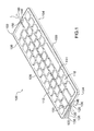
- a foldable keyboard 100 includes an upper housing 102, a lower housing 104 and a spine member or spine 106 configured for attachment to the upper and lower housings and for enabling movement of the upper housing relative to the lower housing.
- the upper housing 102 includes an inner face 108 and an outer face 110 opposite the inner face, with the inner face 108 including a plurality of keys 112.
- the lower housing 104 includes an inner face 114 and an outer face 116 opposite the inner face, where the inner face includes a plurality of keys 118.
- Figure 1 shows the keys 112 and 118 as physical keys, it is appreciated that the keys can also be virtual keys that appear on respective touch screens (not shown).
- the keys of one or both of the upper or lower housings 102, 104 can be recessed relative to the inner face 108 or 110 thereof, such that when the keyboard 100 is in a closed configuration, the keys 112, 118 are not in physical contact with each other.
- Such a recessed configuration may reduce damage to the keys 112, 118 when the keyboard 100 is in the closed configuration.
- such a configuration is not required.
- the upper housing inner face 108 and the lower housing inner face 114 are substantially parallel to each other and define a substantially 180° angle relative to each other.
- the upper housing inner face 108 and the lower housing inner face 114 are substantially planar and flush with each other when the keyboard 100 is in the open configuration.
- the upper housing inner face 108 and the lower housing inner face 114 remain substantially parallel to each other but are now facing towards each other.
- the spine 106 is configured for pivotally connecting the upper and lower housings 102, 104 along a horizontal axis "L" defined by the upper and lower housings.
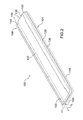
- the spine 106 extends along the entire length or horizontal axis "L" of the upper and lower housings, 102, 104, such that respective opposing ends 120 of the spine are substantially flush with corresponding sidewalls 122, 124 of the upper and lower housings, respectively (see Figure 2 ).
- the spine 106 is further configured to have a height "H", such that a top surface of the spine is flush with the upper housing outer face 110 and an opposing bottom surface of the spine is substantially flush with the lower housing outer face 116.
- a hinge mechanism or assembly 126 which will be described in further detail below, is provided in the keyboard 100 and includes components that are configured for enabling the movement of the upper housing 102 about the horizontal axis L relative to the lower housing 104 to move the keyboard between the closed configuration ( Figure 2 ) and an open configuration ( Figure 1 ).
- a pair of identical hinge assemblies 126 are provided, each located near opposing sidewalls 122, 124 of the upper and lower housings 102, 104, respectively. Accordingly, only one of the hinge assemblies 126 will be described in detail herein.
- the upper housing 102 and the lower housing 104 are approximately the same size, such that when the keyboard 100 is in the closed configuration, the sidewalls 122, 124 and outer edges 128, 130 of the upper and lower housings, respectively, are substantially flush with each other ( Figure 2 ).
- the upper housing 102 may include two rows of keys 112
- the lower housing 104 may include two rows of keys 118 - in other words, approximately 1 ⁇ 2 of the keys are provided on the upper housing, and the remaining 1 ⁇ 2 of the keys are provided on the lower housing.
- the keys 112, 118 can be arranged in vertically staggered columns, similar to the arrangement of a conventional PC or laptop keyboard, although such a configuration is not required. However, it is contemplated that such a vertically staggered column arrangement of the keys 112, 118 lends to easier and more comfortable user typing.
- the keyboard can be easily folded along a break or gap 132 defined between a lowermost row of the keys 112 and an uppermost row of the keys 118.
- the gap 132 defined between the upper housing 102 and the lower housing 104 is located such that the keyboard 100 is divided approximately in half along the horizontal axis "L". This is in contrast to some conventional foldable keyboards, which are typically folded along a vertical axis of the keyboard, thereby preventing the keyboard from having vertically staggered rows as disclosed in the present application.
- the foldable keyboard 100 further includes a stand mechanism 134, which will be described in further detail below.
- the stand mechanism 134 includes a stand 136 configured for translating relative to the upper housing 102 from a first position ( Figure 2 ) to a second position ( Figure 1 ) as the keyboard moves from the closed configuration to the open configuration.
- a recess 138 is defined in the upper housing outer face 110 and is configured for receiving the stand 136 when the stand mechanism is in the first position.
- the stand 136 and corresponding stand recess 138 have substantially the same length as the upper housing 102, and extend parallel to the horizontal axis "L" of the upper housing. In other words, opposing outer sidewalls of the stand 136 are substantially flush with corresponding sidewalls 122 of the upper housing 102.
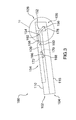
- a width W s of the stand 136 and corresponding recess 138 are less than a width W h of the upper housing 102, as seen in Figures 3 and 4 , for example. Since the stand 136 does not extend the entire width W h of the upper housing 102, there is ample room for the user to grip the upper housing during movement of the stand from the first position to the second position and vice versa.
- the hinge assembly 126 includes, among other things, an upper housing folding pivot 140 and a lower housing folding pivot 142 that are joined together by a folding pivot pin 144 (see Figure 10 , for example).
- the folding pivot pin 144 aids in securing the upper housing 102 to the lower housing 104.
- the folding pivots 140, 142 pivot about the folding pivot pin 144.
- the upper and lower housing folding pivots 140, 142 are located near the sidewalls 122, 124 of the upper and lower housings 102, 104, respectively.
- folding pivots 140, 142 are located between 5-10mm from their corresponding sidewalls 122, 124 to accommodate both the hinge assembly 126 and the stand mechanism 134.
- folding pivots 140, 142 and folding pivot pin 144 are provided near each sidewall 122, 124 of the keyboard 100, as shown in Figure 1 .
- the upper and lower housings 102, 104 further define spine control plate recesses 146, 148, respectively, that are configured for receiving corresponding spine control plates 150 that protrude from the spine 106. More specifically, the upper housing 102 defines a plurality of spine control plate recesses 146 along the axis "L" that are substantially parallel to the upper housing sidewalls 122 and extend into the upper housing so as not to interfere with the upper housing keys 112. Similarly, the lower housing 104 also defines a plurality of spine control plate recesses 148 along the axis "L” that are substantially parallel to the lower housing sidewalls 124 and extend into the lower housing so as not to interfere with the lower housing keys 118.
- spine control plate recesses 146, 148 located closest to the sidewalls 122, 124 are aligned with each other.
- the remaining, internal (i.e., located away from the sidewalls of the upper and lower housings 102, 104) spine control plate recesses 146, 148 are staggered relative to each other so as not to interfere with the staggered arrangement of the keys 112, 118.
- the spine control plates 150 are sized and shaped to fit within each of the corresponding recesses 146, 148, and are secured within the recesses by corresponding control pins ( Figures 10-16 ), which will be described in further detail below.
- the upper and lower housings 102, 104 each define four spine control plate recesses 146, 148; however it is appreciated that more or fewer spine control plate recesses (and accordingly spine control plates 150) may be suitable.
- the disclosed spine control plates and recesses provide a less bulky hinge assembly and a smooth transition of the keyboard between the open and closed configurations.
- the control plate recesses 146, 148 and the spine control plates 150 are substantially rectangular in shape; in other words, they have sharp corners. It is contemplated that this configuration ensures that the gap 132 defined between the upper and lower housings 102, 104 remains as small as possible.
- the stand mechanism 134 of the present keyboard 100 will be described in further detail.
- the stand 136 moves from the first position ( Figure 2 ) to the second position ( Figure 1 ).
- the stand 136 is stored in the upper housing stand recess 138 such that an outer face of the stand is substantially flush and parallel with the upper housing outer face 110.
- the stand 136 defines an angle ⁇ ( Figure 9 ) with the upper housing outer face 110, which will be described in further detail below.
- the stand mechanism 134 further includes a drive bar 152 connected at a first end 154 thereof to the upper housing 102 and at a second end 156 thereof to the lower housing 104.
- the drive bar second end 156 can be secured to a leg that protrudes from the lower housing 104, as seen in Figure 3 , for example.
- the drive bar 152 is slightly hooked or curved in shape so as not to interfere with the hinge assembly (described below with respect to Figures 10-16 ) during opening and closing of the keyboard 100. More specifically, the drive bar 152 extends into the spine 106 during movement of the stand 136, and is shaped to sweep around the hinge assembly 126 without interfering with the hinge assembly and without the need for cuts/indents in the inner faces 108, 114 of the upper and lower housings 102, 104, respectively. Furthermore, the drive bar 152 is shaped and configured such that during movement of the stand mechanism 134, internal components of the spine 106 are not visible.
- a push rod 158 is provided in the upper housing 102 and is connected at a first end 160 thereof to the stand 136 and at a second end 162 thereof to the drive bar first end 154 by a drive bar pin (not shown).
- the upper housing 102 further defines a push rod slot 164 ( Figures 5-9 ) that is configured for slidably receiving the push rod 158 and for enabling sliding movement of the push rod during transition of the stand 136 between the first and second positions.
- a bracing strut 166 is further provided and is connected at a first end 168 thereof to the upper housing 102 and at a second end 170 thereof to the stand 136.
- the bracing strut first end 168 is connected to the upper housing 102 by a bracing strut pivot pin 172 that enables rotation/pivoting of the bracing strut during opening and closing of the keyboard 100.
- the bracing strut 166 is shaped and sized to be received in a corresponding strut recess 174 defined in the upper housing 102 and configured for enabling smooth and controlled movement of the bracing strut during opening and closing of the keyboard 100, as described in more detail below.
- the stand 136 transitions from the first position to the second position. Specifically, as shown in Figure 3 , the stand 136 is in the first position and is stored within the upper housing stand recess 138.
- the drive bar 152 drives the push rod 158 along the push rod slot 164, thereby pivoting the bracing strut 166 and moving the stand 136 from the first position to the second position.
- the drive bar 152 drives the push rod 158 such that it slides within the push rod slot 164 in a direction substantially parallel to the upper housing sidewall 122 and towards the outer edge 128 of the upper housing 102.
- Such driving movement of the push rod 158 translates to the stand 136, which causes the bracing strut 166 to start rotating about the bracing strut pin 172 within the strut recess 174, thereby pushing the stand away from the upper housing until it reaches the second position.
- the bracing strut 166 has reached the end of its rotational travel, the keyboard 100 is in the fully open position and the stand 136 is in the second position ( Figure 9 ), defining the angle ⁇ with the upper housing outer face 110.
- the angle ⁇ is between 20-25° and more specifically is approximately 22.5°. It is contemplated that such an angle ⁇ enables the stand 136 to contact a ground/desk surface such that the upper rows of keys 112 are supported when the keyboard 100 is in the open configuration, thereby preventing the keyboard from toppling or tipping during use.
- the length of the bracing strut 166 dictates the size of the angle ⁇ - in other words, increasing the length of the bracing strut would result in a larger angle ⁇ , whereas decreasing the length of the bracing strut would result in a smaller angle ⁇ .
- the bracing strut 166 also acts as a support when the stand 136 is in the second position to prevent the stand from collapsing back to the first position and to maintain the angle ⁇ defined between the stand and the upper housing outer face 110. As the bracing strut 166 is rotated beyond 90° when the stand 136 is in the second position, no latch, detent or other locking means is necessary to hold the stand in the second position.
- the hinge assembly 126 includes an arc slot 176 defined in the spine plate 150 that is configured for driving rotation of the spine 106 during opening and closing of the keyboard 100.
- the arc slot 176 is arranged at a substantially 45° angle relative to a bottom edge 178 of the spine 106 ( Figure 10 ), although other orientations may be possible.
- the components of the hinge assembly 126 during opening and closing of the keyboard 100 will not interfere with the drive bar 152 and other components of the stand mechanism 134. It is also contemplated that by arranging the arc slot 176 at the substantially 45° angle, the spine 106 is thick/tall enough to include on-board power (not shown) for the keyboard 100.
- the arc slot 176 is configured for receiving a corresponding spine motion drive pin 180 that slides within the arc slot during opening and closing of the keyboard 100. More specifically, the upper housing 102 includes a spine motion drive bar 182, and the spine motion drive pin 180 protrudes from the bar and engages the arc slot 176.
- the hinge assembly further includes a first symmetry control slot 184 in an upper portion of the spine plate 150 and a second symmetry control slot 186 in a lower portion of the spine plate.
- the first and second symmetry control slots 184, 186 are located on opposing sides of the spine plate 150.
- the upper housing 102 includes a first symmetry control pin 188 that is configured for engaging the first symmetry control slot 184 and for sliding within the control slot during opening and closing of the keyboard 100.
- the lower housing 104 includes a second symmetry control pin 190 configured for engaging the second symmetry control slot 186 and for sliding within the control slot during opening and closing of the keyboard 100.
- the drive pin 180 moves within the arc slot 176, which drives the first and second symmetry control pins 188, 190 to move within their respective slots 184, 186, as seen in Figures 11-15 .
- the drive pin bar 182 is received within a drive bar recess 192 (best seen in Figure 14 ) defined in the lower housing spine plate recess 148, and the drive pin 180 is located near the bottom edge 178 of the spine 106 in the arc slot 176.
- the hinge assembly 126 is hidden from view due to the arrangement of the spine control plates 150 in their respective spine control recesses 146, 148.
- the gap 132 defined between the upper and lower housings 102, 104 is minimized due to the construction of the hinge assembly 126 and the upper and lower housings.
- the upper and lower housings 102, 104 each have a substantially rectangular shape with sharp corners that could interfere with the spine 106 during movement.
- the transition between the open and closed configurations is smooth and there is no contact or interference between the spine 106 and the upper and lower housings 102, 104.
- the staggered vertical/columnar arrangement of the keys 112, 118 of the keyboard 100 is not disrupted.
- the configuration of the spine plates 150 and corresponding spine plate recesses 146, 148 along the horizontal axis "L" of the keyboard 100 allows for a substantially slimmer keyboard in comparison to conventional portable keyboards, which typically include mechanical elements only at the outer extremities of the keyboard, thereby requiring thicker keyboards to resist flexion and/or twisting during opening and closing of the keyboard.
- the bottom edge 178 of the spine 106 defines an angle ⁇ with the outer face 116 of the lower housing 104.
- the outer face 116 of the lower housing 104 defines an angle ⁇ with a surface 194 on which the keyboard 100 is resting ( Figure 9 ).
- the angle ⁇ can be approximately 90°.
- the angle ⁇ can be between 5-20° and in the present disclosure is approximately 7.5°, similar to the angle defined by conventional desktop keyboards, for example.
- the present foldable keyboard provides a slim and simple mechanism that folds along the horizontal axis of the keyboard, thereby allowing for an even split amongst the rows of keys and for a simple hinge assembly. This is in contrast to conventional foldable keyboards which typically fold along a vertical axis of the keyboard and require a more complicated hinge assembly due to the staggered nature of the keys.
- the present foldable keyboard provides a layout of keys that is similar to a full-sized staggered keyboard, and as a result the typical pitch and spacing between keys is not disrupted.
- a stand is pushed out from the upper housing of the keyboard to support the opened keyboard at an angle relative to a flat or stable surface.
- the present foldable keyboard stand automatically unfolds or transitions during opening and closing of the keyboard.
- the keys are protected and in some instances can sink relative to their respective housings to prevent direct contact between the keys in the closed configuration.
Landscapes
- Engineering & Computer Science (AREA)
- General Engineering & Computer Science (AREA)
- Theoretical Computer Science (AREA)
- Computer Hardware Design (AREA)
- Human Computer Interaction (AREA)
- Physics & Mathematics (AREA)
- General Physics & Mathematics (AREA)
- Input From Keyboards Or The Like (AREA)
Abstract
Description
- This disclosure is directed to a keyboard and more specifically to a foldable and portable keyboard. Conventional portable keyboards exist for use with electronic devices such as tablet computers or handheld devices, and typically are smaller in size than full-sized keyboards used in conjunction with desktop or laptop computers.
- While conventional portable keyboards may provide a smaller sized device than full-sized keyboards, such smaller sized portable keyboards may prove difficult to accurately type on for users that are more familiar with full-sized keyboards. Further, such portable keyboards can become damaged during travel, which can affect the functionality of the keys. Although foldable keyboards have been developed, due to the typically staggered arrangement of keyboard keys, hinge mechanisms in such foldable keyboards are generally complicated, which can increase costs and chance of malfunction after repeated use. In addition, during use, conventional portable keyboards are generally placed on flat surfaces such that they are planar with the surface, which may decrease user comfort during typing.
-
-
Figure 1 is a front perspective view of a foldable keyboard in an open configuration in accordance with the present disclosure; -
Figure 2 is a front perspective view of the foldable keyboard in a closed configuration; -
Figure 3 is a side view of a stand mechanism of the foldable keyboard in the closed configuration; -
Figure 4 is a side view of the stand mechanism of the foldable keyboard in a first intermediate position; -
Figure 5 is a side view of the stand mechanism of the foldable keyboard in a second intermediate position; -
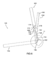
Figure 6 is a side view of the stand mechanism of the foldable keyboard in a third intermediate position; -
Figure 7 is a side view of the stand mechanism of the foldable keyboard in a fourth intermediate position; -
Figure 8 is a side view of the stand mechanism of the foldable keyboard in a fifth intermediate position; -
Figure 9 is a side view of the stand mechanism of the foldable keyboard in the open configuration; -
Figure 10 is a side partial view of portion "10" inFigure 3 showing a hinge mechanism of the foldable keyboard in the closed configuration; -
Figure 11 is a side partial view of portion "11" inFigure 4 showing the hinge mechanism of the foldable keyboard in the first intermediate position; -
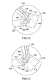
Figure 12 is a side partial view of portion "12" inFigure 5 showing the hinge mechanism of the foldable keyboard in the second intermediate position; -
Figure 13 is a side partial view of portion "13" inFigure 6 showing the hinge mechanism of the foldable keyboard in the third intermediate position; -
Figure 14 is a side partial view of portion "14" inFigure 7 showing the hinge mechanism of the foldable keyboard in the fourth intermediate position; -
Figure 15 is a side partial view of portion "15" inFigure 8 showing the hinge mechanism of the foldable keyboard in the fifth intermediate position; -
Figure 16 is a side partial view of portion "16" inFigure 9 showing the hinge mechanism of the foldable keyboard in the open configuration; and -
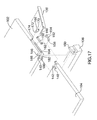
Figure 17 is an exploded side view of the hinge and stand mechanisms of the foldable keyboard. - It will be appreciated that for simplicity and clarity of illustration, where considered appropriate, reference numerals may be repeated among the figures to indicate corresponding or analogous elements. In addition, numerous specific details are set forth in order to provide a thorough understanding of the embodiments described herein. However, it will be understood by those of ordinary skill in the art that the embodiments described herein may be practiced without these specific details. In other instances, well-known methods, procedures and components have not been described in detail so as not to obscure the embodiments described herein. Also, the description is not to be considered as limiting the scope of the embodiments described herein.
- Referring to
Figures 1 and2 , afoldable keyboard 100 is provided and includes anupper housing 102, alower housing 104 and a spine member orspine 106 configured for attachment to the upper and lower housings and for enabling movement of the upper housing relative to the lower housing. Theupper housing 102 includes aninner face 108 and anouter face 110 opposite the inner face, with theinner face 108 including a plurality ofkeys 112. Similarly, thelower housing 104 includes aninner face 114 and anouter face 116 opposite the inner face, where the inner face includes a plurality ofkeys 118. AlthoughFigure 1 shows thekeys physical keys lower housings inner face keyboard 100 is in a closed configuration, thekeys keys keyboard 100 is in the closed configuration. However, such a configuration is not required. - When the
keyboard 100 is in the open configuration (Figure 1 ), the upper housinginner face 108 and the lower housinginner face 114 are substantially parallel to each other and define a substantially 180° angle relative to each other. In other words, the upper housinginner face 108 and the lower housinginner face 114 are substantially planar and flush with each other when thekeyboard 100 is in the open configuration. As shown inFigure 2 , when thekeyboard 100 is in the closed configuration, the upper housinginner face 108 and the lower housinginner face 114 remain substantially parallel to each other but are now facing towards each other. - The
spine 106 is configured for pivotally connecting the upper andlower housings spine 106 extends along the entire length or horizontal axis "L" of the upper and lower housings, 102, 104, such that respectiveopposing ends 120 of the spine are substantially flush withcorresponding sidewalls Figure 2 ). Thespine 106 is further configured to have a height "H", such that a top surface of the spine is flush with the upper housingouter face 110 and an opposing bottom surface of the spine is substantially flush with the lower housingouter face 116. - A hinge mechanism or
assembly 126, which will be described in further detail below, is provided in thekeyboard 100 and includes components that are configured for enabling the movement of theupper housing 102 about the horizontal axis L relative to thelower housing 104 to move the keyboard between the closed configuration (Figure 2 ) and an open configuration (Figure 1 ). Although other configurations may be suitable, in the present disclosure, a pair ofidentical hinge assemblies 126 are provided, each located nearopposing sidewalls lower housings hinge assemblies 126 will be described in detail herein. - In the present disclosure, the
upper housing 102 and thelower housing 104 are approximately the same size, such that when thekeyboard 100 is in the closed configuration, thesidewalls outer edges Figure 2 ). Further, although other configurations may be suitable, in the present disclosure theupper housing 102 may include two rows ofkeys 112, and thelower housing 104 may include two rows of keys 118 - in other words, approximately ½ of the keys are provided on the upper housing, and the remaining ½ of the keys are provided on the lower housing. Thekeys keys - Also, as briefly mentioned above, by dividing the upper and
lower housings keyboard 100 along the horizontal axis L of the keyboard, the keyboard can be easily folded along a break orgap 132 defined between a lowermost row of thekeys 112 and an uppermost row of thekeys 118. In other words, thegap 132 defined between theupper housing 102 and thelower housing 104 is located such that thekeyboard 100 is divided approximately in half along the horizontal axis "L". This is in contrast to some conventional foldable keyboards, which are typically folded along a vertical axis of the keyboard, thereby preventing the keyboard from having vertically staggered rows as disclosed in the present application. If such conventional vertically foldable keyboards were to include vertically staggered columns of keys, it could be difficult to provide a straight or clean gap/break upon which the keyboard could be folded (i.e., a straight vertical axis upon which the keyboard could be folded). In addition, such a vertically folded keyboard could require a rather complex hinge mechanism to enable folding along the vertical axis, in contrast to the present hinge assembly, described in further detail herein. - The
foldable keyboard 100 further includes astand mechanism 134, which will be described in further detail below. Broadly speaking, thestand mechanism 134 includes astand 136 configured for translating relative to theupper housing 102 from a first position (Figure 2 ) to a second position (Figure 1 ) as the keyboard moves from the closed configuration to the open configuration. Arecess 138 is defined in the upper housingouter face 110 and is configured for receiving thestand 136 when the stand mechanism is in the first position. Thestand 136 andcorresponding stand recess 138 have substantially the same length as theupper housing 102, and extend parallel to the horizontal axis "L" of the upper housing. In other words, opposing outer sidewalls of thestand 136 are substantially flush withcorresponding sidewalls 122 of theupper housing 102. In the present disclosure, a width Ws of thestand 136 andcorresponding recess 138 are less than a width Wh of theupper housing 102, as seen inFigures 3 and4 , for example. Since thestand 136 does not extend the entire width Wh of theupper housing 102, there is ample room for the user to grip the upper housing during movement of the stand from the first position to the second position and vice versa. - To enable movement of the
keyboard 100 between the open and closed configurations, thehinge assembly 126 includes, among other things, an upperhousing folding pivot 140 and a lowerhousing folding pivot 142 that are joined together by a folding pivot pin 144 (seeFigure 10 , for example). The foldingpivot pin 144 aids in securing theupper housing 102 to thelower housing 104. As will be described in further detail below, as thekeyboard 100 transitions to the open configuration, the folding pivots 140, 142 pivot about thefolding pivot pin 144. The upper and lower housing folding pivots 140, 142 are located near thesidewalls lower housings sidewalls hinge assembly 126 and thestand mechanism 134. In the present disclosure, folding pivots 140, 142 andfolding pivot pin 144 are provided near eachsidewall keyboard 100, as shown inFigure 1 . - The upper and
lower housings spine control plates 150 that protrude from thespine 106. More specifically, theupper housing 102 defines a plurality of spine control plate recesses 146 along the axis "L" that are substantially parallel to theupper housing sidewalls 122 and extend into the upper housing so as not to interfere with theupper housing keys 112. Similarly, thelower housing 104 also defines a plurality of spine control plate recesses 148 along the axis "L" that are substantially parallel to thelower housing sidewalls 124 and extend into the lower housing so as not to interfere with thelower housing keys 118. As seen inFigure 1 , the spine control plate recesses 146, 148 located closest to thesidewalls lower housings 102, 104) spine control plate recesses 146, 148 are staggered relative to each other so as not to interfere with the staggered arrangement of thekeys spine control plates 150 are sized and shaped to fit within each of the correspondingrecesses Figures 10-16 ), which will be described in further detail below. - In the present disclosure, the upper and
lower housings keyboard 100, the disclosed spine control plates and recesses provide a less bulky hinge assembly and a smooth transition of the keyboard between the open and closed configurations. The control plate recesses 146, 148 and thespine control plates 150 are substantially rectangular in shape; in other words, they have sharp corners. It is contemplated that this configuration ensures that thegap 132 defined between the upper andlower housings - Turning next to
Figures 3-9 , thestand mechanism 134 of thepresent keyboard 100 will be described in further detail. As mentioned briefly above, when thekeyboard 100 transitions from the closed to the open configuration, thestand 136 moves from the first position (Figure 2 ) to the second position (Figure 1 ). In the first position, thestand 136 is stored in the upperhousing stand recess 138 such that an outer face of the stand is substantially flush and parallel with the upper housingouter face 110. In the second position, thestand 136 defines an angle α (Figure 9 ) with the upper housingouter face 110, which will be described in further detail below. To facilitate such movement between the first and second positions, thestand mechanism 134 further includes adrive bar 152 connected at afirst end 154 thereof to theupper housing 102 and at asecond end 156 thereof to thelower housing 104. The drive barsecond end 156 can be secured to a leg that protrudes from thelower housing 104, as seen inFigure 3 , for example. - The
drive bar 152 is slightly hooked or curved in shape so as not to interfere with the hinge assembly (described below with respect toFigures 10-16 ) during opening and closing of thekeyboard 100. More specifically, thedrive bar 152 extends into thespine 106 during movement of thestand 136, and is shaped to sweep around thehinge assembly 126 without interfering with the hinge assembly and without the need for cuts/indents in the inner faces 108, 114 of the upper andlower housings drive bar 152 is shaped and configured such that during movement of thestand mechanism 134, internal components of thespine 106 are not visible. Apush rod 158 is provided in theupper housing 102 and is connected at afirst end 160 thereof to thestand 136 and at asecond end 162 thereof to the drive barfirst end 154 by a drive bar pin (not shown). - The
upper housing 102 further defines a push rod slot 164 (Figures 5-9 ) that is configured for slidably receiving thepush rod 158 and for enabling sliding movement of the push rod during transition of thestand 136 between the first and second positions. A bracingstrut 166 is further provided and is connected at afirst end 168 thereof to theupper housing 102 and at asecond end 170 thereof to thestand 136. The bracing strutfirst end 168 is connected to theupper housing 102 by a bracingstrut pivot pin 172 that enables rotation/pivoting of the bracing strut during opening and closing of thekeyboard 100. The bracingstrut 166 is shaped and sized to be received in acorresponding strut recess 174 defined in theupper housing 102 and configured for enabling smooth and controlled movement of the bracing strut during opening and closing of thekeyboard 100, as described in more detail below. - During movement of the
upper housing 102 relative to thelower housing 104, thestand 136 transitions from the first position to the second position. Specifically, as shown inFigure 3 , thestand 136 is in the first position and is stored within the upperhousing stand recess 138. Turning toFigures 4-9 , as thekeyboard 100 is opened, thedrive bar 152 drives thepush rod 158 along thepush rod slot 164, thereby pivoting the bracingstrut 166 and moving thestand 136 from the first position to the second position. During this movement, thedrive bar 152 drives thepush rod 158 such that it slides within thepush rod slot 164 in a direction substantially parallel to theupper housing sidewall 122 and towards theouter edge 128 of theupper housing 102. Such driving movement of thepush rod 158 translates to thestand 136, which causes the bracingstrut 166 to start rotating about the bracingstrut pin 172 within thestrut recess 174, thereby pushing the stand away from the upper housing until it reaches the second position. When the bracingstrut 166 has reached the end of its rotational travel, thekeyboard 100 is in the fully open position and thestand 136 is in the second position (Figure 9 ), defining the angle α with the upper housingouter face 110. - Although other angles may be suitable, in the present disclosure, the angle α is between 20-25° and more specifically is approximately 22.5°. It is contemplated that such an angle α enables the
stand 136 to contact a ground/desk surface such that the upper rows ofkeys 112 are supported when thekeyboard 100 is in the open configuration, thereby preventing the keyboard from toppling or tipping during use. The length of the bracingstrut 166 dictates the size of the angle α - in other words, increasing the length of the bracing strut would result in a larger angle α, whereas decreasing the length of the bracing strut would result in a smaller angle α. The bracingstrut 166 also acts as a support when thestand 136 is in the second position to prevent the stand from collapsing back to the first position and to maintain the angle α defined between the stand and the upper housingouter face 110. As the bracingstrut 166 is rotated beyond 90° when thestand 136 is in the second position, no latch, detent or other locking means is necessary to hold the stand in the second position. - As the
stand mechanism 134 is deployed as described above, thehinge assembly 126 in thespine 106 simultaneously enables thekeyboard 100 to transition from the closed to the open configuration, as will now be described with respect toFigures 10-17 . Thehinge assembly 126 includes anarc slot 176 defined in thespine plate 150 that is configured for driving rotation of thespine 106 during opening and closing of thekeyboard 100. In the present disclosure, thearc slot 176 is arranged at a substantially 45° angle relative to abottom edge 178 of the spine 106 (Figure 10 ), although other orientations may be possible. It is contemplated that by arranging thearc slot 176 at the substantially 45° angle, the components of thehinge assembly 126 during opening and closing of thekeyboard 100 will not interfere with thedrive bar 152 and other components of thestand mechanism 134. It is also contemplated that by arranging thearc slot 176 at the substantially 45° angle, thespine 106 is thick/tall enough to include on-board power (not shown) for thekeyboard 100. Thearc slot 176 is configured for receiving a corresponding spinemotion drive pin 180 that slides within the arc slot during opening and closing of thekeyboard 100. More specifically, theupper housing 102 includes a spinemotion drive bar 182, and the spinemotion drive pin 180 protrudes from the bar and engages thearc slot 176. - The hinge assembly further includes a first
symmetry control slot 184 in an upper portion of thespine plate 150 and a secondsymmetry control slot 186 in a lower portion of the spine plate. In the present disclosure, the first and secondsymmetry control slots spine plate 150. Theupper housing 102 includes a firstsymmetry control pin 188 that is configured for engaging the firstsymmetry control slot 184 and for sliding within the control slot during opening and closing of thekeyboard 100. Similarly, thelower housing 104 includes a secondsymmetry control pin 190 configured for engaging the secondsymmetry control slot 186 and for sliding within the control slot during opening and closing of thekeyboard 100. - As the
keyboard 100 is transitioned from the closed configuration (Figure 10 ) to the open configuration (Figure 16 ), thedrive pin 180 moves within thearc slot 176, which drives the first and second symmetry control pins 188, 190 to move within theirrespective slots Figures 11-15 . Once in the open configuration (Figure 16 ), thedrive pin bar 182 is received within a drive bar recess 192 (best seen inFigure 14 ) defined in the lower housingspine plate recess 148, and thedrive pin 180 is located near thebottom edge 178 of thespine 106 in thearc slot 176. During opening and closing of thekeyboard 100, thehinge assembly 126 is hidden from view due to the arrangement of thespine control plates 150 in their respective spine control recesses 146, 148. - In the open configuration (
Figures 1 and16 ), thegap 132 defined between the upper andlower housings hinge assembly 126 and the upper and lower housings. Specifically, the upper andlower housings spine 106 during movement. However, due to the configuration of thearc slot 176 and first and secondsymmetry control slots spine 106 and the upper andlower housings spine plates 150, the staggered vertical/columnar arrangement of thekeys keyboard 100 is not disrupted. Furthermore, the configuration of thespine plates 150 and corresponding spine plate recesses 146, 148 along the horizontal axis "L" of thekeyboard 100 allows for a substantially slimmer keyboard in comparison to conventional portable keyboards, which typically include mechanical elements only at the outer extremities of the keyboard, thereby requiring thicker keyboards to resist flexion and/or twisting during opening and closing of the keyboard. - When the
keyboard 100 is in the open configuration, thebottom edge 178 of thespine 106 defines an angle β with theouter face 116 of thelower housing 104. In addition, theouter face 116 of thelower housing 104 defines an angle γ with asurface 194 on which thekeyboard 100 is resting (Figure 9 ). In the present disclosure, the angle β can be approximately 90°. To provide an ergonomic typing surface, the angle γ can be between 5-20° and in the present disclosure is approximately 7.5°, similar to the angle defined by conventional desktop keyboards, for example. - The present foldable keyboard provides a slim and simple mechanism that folds along the horizontal axis of the keyboard, thereby allowing for an even split amongst the rows of keys and for a simple hinge assembly. This is in contrast to conventional foldable keyboards which typically fold along a vertical axis of the keyboard and require a more complicated hinge assembly due to the staggered nature of the keys. The present foldable keyboard provides a layout of keys that is similar to a full-sized staggered keyboard, and as a result the typical pitch and spacing between keys is not disrupted. During opening and closing of the keyboard, a stand is pushed out from the upper housing of the keyboard to support the opened keyboard at an angle relative to a flat or stable surface. The present foldable keyboard stand automatically unfolds or transitions during opening and closing of the keyboard. When the foldable keyboard is in the closed configuration, the keys are protected and in some instances can sink relative to their respective housings to prevent direct contact between the keys in the closed configuration.
- While a particular embodiment of the present foldable keyboard has been described herein, it will be appreciated by those skilled in the art that changes and modifications may be made thereto without departing from the disclosure in its broadest aspects and as set forth below:
- 1. A foldable keyboard comprising:
- an upper housing having a plurality of keys;
- a lower housing having a plurality of keys;
- a spine member configured for pivotally connecting the upper and lower housings along a horizontal axis defined by the upper and lower housings; and
- a hinge mechanism provided in the spine member and configured for enabling movement of the upper housing relative to the lower housing to move the keyboard between a closed configuration and an open configuration.
- 2. The foldable keyboard of item 1 further including a stand mechanism including a stand configured for pivoting relative to the upper housing from a first position to a second position as the keyboard moves from the closed configuration to the open configuration.
- 3. The foldable keyboard of item 2 further including a recess defined in the upper housing and configured for receiving the stand mechanism.
- 4. The foldable keyboard of item 2 wherein the upper housing includes an inner face and an outer face, and wherein when the keyboard is in the open configuration, the stand is in the second position and defines an angle relative to the outer face.
- 5. The foldable keyboard of item 4 wherein in the closed configuration, a top surface of the spine is flush with an outer face of the upper housing.
- 6. The foldable keyboard of item 4 wherein in the closed configuration, a bottom surface of the spine is flush with an outer face of the lower housing.
- 7. The foldable keyboard of item 6 wherein in the open configuration, the bottom surface of the spine defines an angle with the outer face of the lower housing.
- 8. The foldable keyboard of item 2 wherein the hinge mechanism includes:
- a slot defined in the spine;
- a pivot bar having a pivot pin at a first end thereof, the pivot pin configured for being received in the slot;
- an upper housing slot defined in the spine and configured for receiving a corresponding upper housing pin; and
- a lower housing slot defined in the spine and configured for receiving a corresponding lower housing pin.
- 9. The foldable keyboard of item 8 wherein the pivot bar includes a second end that is attached to the upper housing, and wherein during movement of the upper housing relative to the lower housing, the pivot pin slides within the slot.
- 10. The foldable keyboard of item 1 further including:
- at least one spine plate extending from the upper housing;
- at least one spine plate extending from the lower housing; and
- at least one spine plate recess defined in the spine;
- wherein each spine plate recess is configured for receiving a corresponding spine plate, the spine plate recess and corresponding spine plate being pivotally connected by a corresponding pin.
- 11. The foldable keyboard of item 2 wherein the stand mechanism further includes:
- a drive bar connected at a first end to the upper housing and at a second end to the lower housing;
- a push rod connected at a first end to the stand and at a second end to the upper housing;
- a push rod slot defined in the upper housing and configured for slidably receiving the push rod; and
- a bracing strut connected at a first end to the upper housing and at a second end to the stand;
- wherein during movement of the upper housing relative to the lower housing, the drive bar drives the push rod along the push rod slot, thereby pivoting the bracing strut and moving the stand from the first position to the second position.
- 12. The foldable keyboard of
item 11 wherein the upper housing further defines a strut recess configured for receiving the bracing strut and allowing pivotable movement thereof during movement of the stand between the first and second positions. - 13. The foldable keyboard of
item 11 wherein the stand mechanism further includes a leg having a first end connected to the lower housing and a second end connected to the second end of the drive bar. - 14. The foldable keyboard of item 1 wherein in the closed configuration, the keys on the lower housing are recessed relative to an inner face of the upper housing.
- 15. A foldable keyboard comprising:
- an upper housing having an inner face and an outer face;
- a stand mechanism connected to the upper housing and including a stand;
- a lower housing having an inner face and an outer face;
- a spine configured for connecting the upper and lower housings along a horizontal axis of the upper and lower housings; and
- a hinge mechanism provided in the spine and being configured to enable movement of the upper housing relative to the lower housing during movement of the foldable keyboard between a closed configuration and an open configuration;
- wherein during movement of the keyboard between the closed configuration and the open configuration, the stand is configured to rotate relative to the outer face of the upper housing from a first position to a second position.
- 16. The keyboard of
item 15 wherein the inner face of the upper housing includes a plurality of keys. - 17. The keyboard of
item 15 wherein the inner face of the lower housing includes a plurality of keys. - 18. The foldable keyboard of
item 15 wherein the hinge mechanism includes:- a slot defined in the spine;
- a pivot bar having a pivot pin at a first end thereof, the pivot pin configured for being received in the slot;
- an upper housing slot defined in the spine and configured for receiving a corresponding upper housing pin; and
- a lower housing slot defined in the spine and configured for receiving a corresponding lower housing pin.
- 19. The foldable keyboard of
item 15 wherein the stand mechanism further includes:- a drive bar connected at a first end to the upper housing and at a second end to the lower housing;
- a push rod connected at a first end to the stand and at a second end to the upper housing;
- a push rod slot defined in the upper housing and configured for slidably receiving the push rod; and
- a bracing strut connected at a first end to the upper housing and at a second end to the stand;
- wherein during movement of the upper housing relative to the lower housing, the drive bar drives the push rod along the push rod slot, thereby pivoting the bracing strut and moving the stand from the first position to the second position.
- 20. A keyboard comprising:
- an upper housing having an inner face, an outer face and a recess defined in the outer face;
- a stand connected to the upper housing and configured for being received in the recess when the stand is in a first position;
- a lower housing having an inner face and an outer face;
- a hinge mechanism connecting the upper housing and the lower housing along a horizontal axis defined by the upper housing and the lower housing, the hinge mechanism being configured to enable movement of the upper housing relative to the lower housing during movement of the keyboard between a closed configuration and an open configuration; and
- a spine configured for enclosing the hinge mechanism, the spine including a bottom surface that defines an angle with the outer face of the lower housing when the keyboard is in the open configuration;
- wherein during movement of the keyboard between the closed configuration and the open configuration, the stand is configured to rotate relative to the outer face of the upper housing from the first position to a second position.
Claims (16)
- A foldable keyboard comprising:an upper housing;a lower housing;a spine member configured for pivotally connecting the upper and lower housings along a horizontal axis defined by the upper and lower housings; anda hinge mechanism provided in the spine member and configured for enabling movement of the upper housing relative to the lower housing to move the keyboard between a closed configuration and an open configuration.
- The foldable keyboard of claim 1 further including a stand mechanism including a stand configured for pivoting relative to the upper housing from a first position to a second position as the keyboard moves from the closed configuration to the open configuration.
- The foldable keyboard of claim 2 further including a recess defined in the upper housing and configured for receiving the stand mechanism.
- The foldable keyboard of claim 2 wherein the upper housing includes an inner face and an outer face, and wherein when the keyboard is in the open configuration, the stand is in the second position and defines an angle relative to the outer face.
- The foldable keyboard of claim 4 wherein in the closed configuration, a top surface of the spine is flush with an outer face of the upper housing.
- The foldable keyboard of claim 4 wherein in the closed configuration, a bottom surface of the spine is flush with an outer face of the lower housing.
- The foldable keyboard of claim 6 wherein in the open configuration, the bottom surface of the spine defines an angle with the outer face of the lower housing.
- The foldable keyboard of claim 2 wherein the hinge mechanism includes:a slot defined in the spine;a pivot bar having a pivot pin at a first end thereof, the pivot pin configured for being received in the slot;an upper housing slot defined in the spine and configured for receiving a corresponding upper housing pin; anda lower housing slot defined in the spine and configured for receiving a corresponding lower housing pin.
- The foldable keyboard of claim 8 wherein the pivot bar includes a second end that is attached to the upper housing, and wherein during movement of the upper housing relative to the lower housing, the pivot pin slides within the slot.
- The foldable keyboard of claim 1 further including:at least one spine plate extending from the upper housing;at least one spine plate extending from the lower housing; andat least one spine plate recess defined in the spine;wherein each spine plate recess is configured for receiving a corresponding spine plate, the spine plate recess and corresponding spine plate being pivotally connected by a corresponding pin.
- The foldable keyboard of claim 2 wherein the stand mechanism further includes:a drive bar connected at a first end to the upper housing and at a second end to the lower housing;a push rod connected at a first end to the stand and at a second end to the upper housing;a push rod slot defined in the upper housing and configured for slidably receiving the push rod; anda bracing strut connected at a first end to the upper housing and at a second end to the stand;wherein during movement of the upper housing relative to the lower housing, the drive bar drives the push rod along the push rod slot, thereby pivoting the bracing strut and moving the stand from the first position to the second position.
- The foldable keyboard of claim 11 wherein the upper housing further defines a strut recess configured for receiving the bracing strut and allowing pivotable movement thereof during movement of the stand between the first and second positions.
- The foldable keyboard of claim 11 wherein the stand mechanism further includes a leg having a first end connected to the lower housing and a second end connected to the second end of the drive bar.
- The foldable keyboard of claim 1 wherein in the closed configuration, the keys on the lower housing are recessed relative to an inner face of the upper housing.
- The foldable keyboard of any one of the preceding claims in which the upper housing has a plurality of keys; and the lower housing has a plurality of keys.
- The foldable keyboard of claim 1, in which
the upper housing has an inner face and an outer face;
the lower housing has an inner face and an outer face;
and further including
a stand mechanism connected to the upper housing and including a stand;
wherein during movement of the keyboard between the closed configuration and the open configuration, the stand is configured to rotate relative to the outer face of the upper housing from a first position to a second position.
Priority Applications (1)
| Application Number | Priority Date | Filing Date | Title |
|---|---|---|---|
| EP20120187865 EP2720116B1 (en) | 2012-10-09 | 2012-10-09 | Foldable keyboard |
Applications Claiming Priority (1)
| Application Number | Priority Date | Filing Date | Title |
|---|---|---|---|
| EP20120187865 EP2720116B1 (en) | 2012-10-09 | 2012-10-09 | Foldable keyboard |
Publications (2)
| Publication Number | Publication Date |
|---|---|
| EP2720116A1 true EP2720116A1 (en) | 2014-04-16 |
| EP2720116B1 EP2720116B1 (en) | 2015-04-08 |
Family
ID=47010374
Family Applications (1)
| Application Number | Title | Priority Date | Filing Date |
|---|---|---|---|
| EP20120187865 Active EP2720116B1 (en) | 2012-10-09 | 2012-10-09 | Foldable keyboard |
Country Status (1)
| Country | Link |
|---|---|
| EP (1) | EP2720116B1 (en) |
Citations (7)
| Publication number | Priority date | Publication date | Assignee | Title |
|---|---|---|---|---|
| GB2128783A (en) * | 1982-10-18 | 1984-05-02 | Grid Systems Corp | Portable computer |
| US4610415A (en) * | 1983-06-22 | 1986-09-09 | Decision Data Computer Corporation | Tiltable support |
| US6053589A (en) * | 1998-09-10 | 2000-04-25 | Inventec Corp. | Automatic inclination device for a portable computer |
| US20040104897A1 (en) * | 2002-12-02 | 2004-06-03 | Brother Kogyo Kabushiki Kaisha | Foldable keyboard |
| US20060138913A1 (en) * | 2000-08-09 | 2006-06-29 | Si Kim | Case for portable display devices |
| EP2421229A2 (en) * | 2010-08-20 | 2012-02-22 | Research In Motion Limited | Clam-shell type mobile device |
| US20120127258A1 (en) * | 1998-04-24 | 2012-05-24 | Henty David L | Remote control with top and lower surface inputs |
-
2012
- 2012-10-09 EP EP20120187865 patent/EP2720116B1/en active Active
Patent Citations (7)
| Publication number | Priority date | Publication date | Assignee | Title |
|---|---|---|---|---|
| GB2128783A (en) * | 1982-10-18 | 1984-05-02 | Grid Systems Corp | Portable computer |
| US4610415A (en) * | 1983-06-22 | 1986-09-09 | Decision Data Computer Corporation | Tiltable support |
| US20120127258A1 (en) * | 1998-04-24 | 2012-05-24 | Henty David L | Remote control with top and lower surface inputs |
| US6053589A (en) * | 1998-09-10 | 2000-04-25 | Inventec Corp. | Automatic inclination device for a portable computer |
| US20060138913A1 (en) * | 2000-08-09 | 2006-06-29 | Si Kim | Case for portable display devices |
| US20040104897A1 (en) * | 2002-12-02 | 2004-06-03 | Brother Kogyo Kabushiki Kaisha | Foldable keyboard |
| EP2421229A2 (en) * | 2010-08-20 | 2012-02-22 | Research In Motion Limited | Clam-shell type mobile device |
Also Published As
| Publication number | Publication date |
|---|---|
| EP2720116B1 (en) | 2015-04-08 |
Similar Documents
| Publication | Publication Date | Title |
|---|---|---|
| US8941979B2 (en) | Foldable keyboard | |
| CN105190488B (en) | Foldable keyboard with adjustable ergonomic features | |
| CN102405139B (en) | Adjustable ergonomic keyboards and portable computing devices | |
| KR102034585B1 (en) | Display Device | |
| TWI550384B (en) | Tilt mechanism for information device | |
| US9678535B2 (en) | Moveable keyboard lattice for a portable electronic device | |
| JP4868705B2 (en) | Movable console device | |
| US8154868B2 (en) | Electronic device | |
| US9047058B2 (en) | Electronic device with support mechanism | |
| US20150282354A1 (en) | Multi viewing angle portable electronic device support | |
| CN112150931B (en) | Supporting structural part and display device | |
| EP3999930B1 (en) | Computing devices with retractable hinges | |
| CN110865682A (en) | Laptop computer with multiple displays | |
| TWI519933B (en) | Electronic device with foldable/unfoldable function | |
| CN105700629A (en) | Portable computer | |
| US9329637B2 (en) | Configurable ergonomic keyboard for computing devices | |
| EP2720116A1 (en) | Foldable keyboard | |
| US20220050532A1 (en) | Keyboard with an independent bracket | |
| CN203117854U (en) | Foldable notebook computer | |
| JP5289362B2 (en) | Movable console device | |
| CN209433278U (en) | Electronic equipment | |
| CN209450182U (en) | A kind of Foldable bed cabinet | |
| KR20110068712A (en) | Folding keyboard with multiple hinges | |
| KR200286419Y1 (en) | Portable Keyboard | |
| CN117685288A (en) | Damping structure and scanning pen |
Legal Events
| Date | Code | Title | Description |
|---|---|---|---|
| PUAI | Public reference made under article 153(3) epc to a published international application that has entered the european phase |
Free format text: ORIGINAL CODE: 0009012 |
|
| 17P | Request for examination filed |
Effective date: 20121009 |
|
| AK | Designated contracting states |
Kind code of ref document: A1 Designated state(s): AL AT BE BG CH CY CZ DE DK EE ES FI FR GB GR HR HU IE IS IT LI LT LU LV MC MK MT NL NO PL PT RO RS SE SI SK SM TR |
|
| AX | Request for extension of the european patent |
Extension state: BA ME |
|
| 17Q | First examination report despatched |
Effective date: 20140429 |
|
| REG | Reference to a national code |
Ref country code: DE Ref legal event code: R079 Ref document number: 602012006444 Country of ref document: DE Free format text: PREVIOUS MAIN CLASS: G06F0003020000 Ipc: H01H0013860000 |
|
| GRAP | Despatch of communication of intention to grant a patent |
Free format text: ORIGINAL CODE: EPIDOSNIGR1 |
|
| RIC1 | Information provided on ipc code assigned before grant |
Ipc: H01H 13/86 20060101AFI20141020BHEP |
|
| INTG | Intention to grant announced |
Effective date: 20141105 |
|
| RIC1 | Information provided on ipc code assigned before grant |
Ipc: H01H 13/86 20060101AFI20141027BHEP Ipc: G06F 3/02 20060101ALI20141027BHEP |
|
| GRAS | Grant fee paid |
Free format text: ORIGINAL CODE: EPIDOSNIGR3 |
|
| GRAA | (expected) grant |
Free format text: ORIGINAL CODE: 0009210 |
|
| AK | Designated contracting states |
Kind code of ref document: B1 Designated state(s): AL AT BE BG CH CY CZ DE DK EE ES FI FR GB GR HR HU IE IS IT LI LT LU LV MC MK MT NL NO PL PT RO RS SE SI SK SM TR |
|
| REG | Reference to a national code |
Ref country code: GB Ref legal event code: FG4D |
|
| REG | Reference to a national code |
Ref country code: CH Ref legal event code: EP |
|
| REG | Reference to a national code |
Ref country code: IE Ref legal event code: FG4D |
|
| REG | Reference to a national code |
Ref country code: AT Ref legal event code: REF Ref document number: 721096 Country of ref document: AT Kind code of ref document: T Effective date: 20150515 |
|
| REG | Reference to a national code |
Ref country code: DE Ref legal event code: R096 Ref document number: 602012006444 Country of ref document: DE Effective date: 20150521 |
|
| REG | Reference to a national code |
Ref country code: AT Ref legal event code: MK05 Ref document number: 721096 Country of ref document: AT Kind code of ref document: T Effective date: 20150408 |
|
| REG | Reference to a national code |
Ref country code: LT Ref legal event code: MG4D |
|
| REG | Reference to a national code |
Ref country code: FR Ref legal event code: PLFP Year of fee payment: 4 |
|
| PG25 | Lapsed in a contracting state [announced via postgrant information from national office to epo] |
Ref country code: LT Free format text: LAPSE BECAUSE OF FAILURE TO SUBMIT A TRANSLATION OF THE DESCRIPTION OR TO PAY THE FEE WITHIN THE PRESCRIBED TIME-LIMIT Effective date: 20150408 Ref country code: PT Free format text: LAPSE BECAUSE OF FAILURE TO SUBMIT A TRANSLATION OF THE DESCRIPTION OR TO PAY THE FEE WITHIN THE PRESCRIBED TIME-LIMIT Effective date: 20150810 Ref country code: HR Free format text: LAPSE BECAUSE OF FAILURE TO SUBMIT A TRANSLATION OF THE DESCRIPTION OR TO PAY THE FEE WITHIN THE PRESCRIBED TIME-LIMIT Effective date: 20150408 Ref country code: NO Free format text: LAPSE BECAUSE OF FAILURE TO SUBMIT A TRANSLATION OF THE DESCRIPTION OR TO PAY THE FEE WITHIN THE PRESCRIBED TIME-LIMIT Effective date: 20150708 Ref country code: FI Free format text: LAPSE BECAUSE OF FAILURE TO SUBMIT A TRANSLATION OF THE DESCRIPTION OR TO PAY THE FEE WITHIN THE PRESCRIBED TIME-LIMIT Effective date: 20150408 Ref country code: ES Free format text: LAPSE BECAUSE OF FAILURE TO SUBMIT A TRANSLATION OF THE DESCRIPTION OR TO PAY THE FEE WITHIN THE PRESCRIBED TIME-LIMIT Effective date: 20150408 |
|
| PG25 | Lapsed in a contracting state [announced via postgrant information from national office to epo] |
Ref country code: IS Free format text: LAPSE BECAUSE OF FAILURE TO SUBMIT A TRANSLATION OF THE DESCRIPTION OR TO PAY THE FEE WITHIN THE PRESCRIBED TIME-LIMIT Effective date: 20150808 Ref country code: GR Free format text: LAPSE BECAUSE OF FAILURE TO SUBMIT A TRANSLATION OF THE DESCRIPTION OR TO PAY THE FEE WITHIN THE PRESCRIBED TIME-LIMIT Effective date: 20150709 Ref country code: LV Free format text: LAPSE BECAUSE OF FAILURE TO SUBMIT A TRANSLATION OF THE DESCRIPTION OR TO PAY THE FEE WITHIN THE PRESCRIBED TIME-LIMIT Effective date: 20150408 Ref country code: AT Free format text: LAPSE BECAUSE OF FAILURE TO SUBMIT A TRANSLATION OF THE DESCRIPTION OR TO PAY THE FEE WITHIN THE PRESCRIBED TIME-LIMIT Effective date: 20150408 Ref country code: RS Free format text: LAPSE BECAUSE OF FAILURE TO SUBMIT A TRANSLATION OF THE DESCRIPTION OR TO PAY THE FEE WITHIN THE PRESCRIBED TIME-LIMIT Effective date: 20150408 |
|
| REG | Reference to a national code |
Ref country code: DE Ref legal event code: R097 Ref document number: 602012006444 Country of ref document: DE |
|
| PG25 | Lapsed in a contracting state [announced via postgrant information from national office to epo] |
Ref country code: DK Free format text: LAPSE BECAUSE OF FAILURE TO SUBMIT A TRANSLATION OF THE DESCRIPTION OR TO PAY THE FEE WITHIN THE PRESCRIBED TIME-LIMIT Effective date: 20150408 Ref country code: EE Free format text: LAPSE BECAUSE OF FAILURE TO SUBMIT A TRANSLATION OF THE DESCRIPTION OR TO PAY THE FEE WITHIN THE PRESCRIBED TIME-LIMIT Effective date: 20150408 |
|
| PLBE | No opposition filed within time limit |
Free format text: ORIGINAL CODE: 0009261 |
|
| STAA | Information on the status of an ep patent application or granted ep patent |
Free format text: STATUS: NO OPPOSITION FILED WITHIN TIME LIMIT |
|
| PG25 | Lapsed in a contracting state [announced via postgrant information from national office to epo] |
Ref country code: SK Free format text: LAPSE BECAUSE OF FAILURE TO SUBMIT A TRANSLATION OF THE DESCRIPTION OR TO PAY THE FEE WITHIN THE PRESCRIBED TIME-LIMIT Effective date: 20150408 Ref country code: PL Free format text: LAPSE BECAUSE OF FAILURE TO SUBMIT A TRANSLATION OF THE DESCRIPTION OR TO PAY THE FEE WITHIN THE PRESCRIBED TIME-LIMIT Effective date: 20150408 Ref country code: CZ Free format text: LAPSE BECAUSE OF FAILURE TO SUBMIT A TRANSLATION OF THE DESCRIPTION OR TO PAY THE FEE WITHIN THE PRESCRIBED TIME-LIMIT Effective date: 20150408 Ref country code: RO Free format text: LAPSE BECAUSE OF NON-PAYMENT OF DUE FEES Effective date: 20150408 |
|
| 26N | No opposition filed |
Effective date: 20160111 |
|
| PG25 | Lapsed in a contracting state [announced via postgrant information from national office to epo] |
Ref country code: IT Free format text: LAPSE BECAUSE OF FAILURE TO SUBMIT A TRANSLATION OF THE DESCRIPTION OR TO PAY THE FEE WITHIN THE PRESCRIBED TIME-LIMIT Effective date: 20150408 |
|
| PG25 | Lapsed in a contracting state [announced via postgrant information from national office to epo] |
Ref country code: SI Free format text: LAPSE BECAUSE OF FAILURE TO SUBMIT A TRANSLATION OF THE DESCRIPTION OR TO PAY THE FEE WITHIN THE PRESCRIBED TIME-LIMIT Effective date: 20150408 Ref country code: LU Free format text: LAPSE BECAUSE OF FAILURE TO SUBMIT A TRANSLATION OF THE DESCRIPTION OR TO PAY THE FEE WITHIN THE PRESCRIBED TIME-LIMIT Effective date: 20151009 |
|
| REG | Reference to a national code |
Ref country code: CH Ref legal event code: PL |
|
| PG25 | Lapsed in a contracting state [announced via postgrant information from national office to epo] |
Ref country code: MC Free format text: LAPSE BECAUSE OF FAILURE TO SUBMIT A TRANSLATION OF THE DESCRIPTION OR TO PAY THE FEE WITHIN THE PRESCRIBED TIME-LIMIT Effective date: 20150408 |
|
| REG | Reference to a national code |
Ref country code: IE Ref legal event code: MM4A |
|
| PG25 | Lapsed in a contracting state [announced via postgrant information from national office to epo] |
Ref country code: CH Free format text: LAPSE BECAUSE OF NON-PAYMENT OF DUE FEES Effective date: 20151031 Ref country code: LI Free format text: LAPSE BECAUSE OF NON-PAYMENT OF DUE FEES Effective date: 20151031 |
|
| PG25 | Lapsed in a contracting state [announced via postgrant information from national office to epo] |
Ref country code: BE Free format text: LAPSE BECAUSE OF FAILURE TO SUBMIT A TRANSLATION OF THE DESCRIPTION OR TO PAY THE FEE WITHIN THE PRESCRIBED TIME-LIMIT Effective date: 20150408 |
|
| REG | Reference to a national code |
Ref country code: FR Ref legal event code: PLFP Year of fee payment: 5 |
|
| PG25 | Lapsed in a contracting state [announced via postgrant information from national office to epo] |
Ref country code: IE Free format text: LAPSE BECAUSE OF NON-PAYMENT OF DUE FEES Effective date: 20151009 |
|
| PG25 | Lapsed in a contracting state [announced via postgrant information from national office to epo] |
Ref country code: HU Free format text: LAPSE BECAUSE OF FAILURE TO SUBMIT A TRANSLATION OF THE DESCRIPTION OR TO PAY THE FEE WITHIN THE PRESCRIBED TIME-LIMIT; INVALID AB INITIO Effective date: 20121009 Ref country code: SM Free format text: LAPSE BECAUSE OF FAILURE TO SUBMIT A TRANSLATION OF THE DESCRIPTION OR TO PAY THE FEE WITHIN THE PRESCRIBED TIME-LIMIT Effective date: 20150408 Ref country code: BG Free format text: LAPSE BECAUSE OF FAILURE TO SUBMIT A TRANSLATION OF THE DESCRIPTION OR TO PAY THE FEE WITHIN THE PRESCRIBED TIME-LIMIT Effective date: 20150408 |
|
| PG25 | Lapsed in a contracting state [announced via postgrant information from national office to epo] |
Ref country code: SE Free format text: LAPSE BECAUSE OF FAILURE TO SUBMIT A TRANSLATION OF THE DESCRIPTION OR TO PAY THE FEE WITHIN THE PRESCRIBED TIME-LIMIT Effective date: 20150408 Ref country code: CY Free format text: LAPSE BECAUSE OF FAILURE TO SUBMIT A TRANSLATION OF THE DESCRIPTION OR TO PAY THE FEE WITHIN THE PRESCRIBED TIME-LIMIT Effective date: 20150408 |
|
| PG25 | Lapsed in a contracting state [announced via postgrant information from national office to epo] |
Ref country code: MT Free format text: LAPSE BECAUSE OF FAILURE TO SUBMIT A TRANSLATION OF THE DESCRIPTION OR TO PAY THE FEE WITHIN THE PRESCRIBED TIME-LIMIT Effective date: 20150408 |
|
| REG | Reference to a national code |
Ref country code: FR Ref legal event code: PLFP Year of fee payment: 6 |
|
| PG25 | Lapsed in a contracting state [announced via postgrant information from national office to epo] |
Ref country code: MK Free format text: LAPSE BECAUSE OF FAILURE TO SUBMIT A TRANSLATION OF THE DESCRIPTION OR TO PAY THE FEE WITHIN THE PRESCRIBED TIME-LIMIT Effective date: 20150408 |
|
| REG | Reference to a national code |
Ref country code: FR Ref legal event code: PLFP Year of fee payment: 7 |
|
| PG25 | Lapsed in a contracting state [announced via postgrant information from national office to epo] |
Ref country code: TR Free format text: LAPSE BECAUSE OF FAILURE TO SUBMIT A TRANSLATION OF THE DESCRIPTION OR TO PAY THE FEE WITHIN THE PRESCRIBED TIME-LIMIT Effective date: 20150408 Ref country code: AL Free format text: LAPSE BECAUSE OF FAILURE TO SUBMIT A TRANSLATION OF THE DESCRIPTION OR TO PAY THE FEE WITHIN THE PRESCRIBED TIME-LIMIT Effective date: 20150408 |
|
| REG | Reference to a national code |
Ref country code: DE Ref legal event code: R082 Ref document number: 602012006444 Country of ref document: DE Ref country code: DE Ref legal event code: R081 Ref document number: 602012006444 Country of ref document: DE Owner name: MALIKIE INNOVATIONS LTD., IE Free format text: FORMER OWNER: BLACKBERRY LIMITED, WATERLOO, ONTARIO, CA |
|
| REG | Reference to a national code |
Ref country code: GB Ref legal event code: 732E Free format text: REGISTERED BETWEEN 20240620 AND 20240627 |
|
| PGFP | Annual fee paid to national office [announced via postgrant information from national office to epo] |
Ref country code: NL Payment date: 20251024 Year of fee payment: 14 |
|
| PGFP | Annual fee paid to national office [announced via postgrant information from national office to epo] |
Ref country code: DE Payment date: 20251028 Year of fee payment: 14 |
|
| PGFP | Annual fee paid to national office [announced via postgrant information from national office to epo] |
Ref country code: GB Payment date: 20251023 Year of fee payment: 14 |
|
| PGFP | Annual fee paid to national office [announced via postgrant information from national office to epo] |
Ref country code: FR Payment date: 20251027 Year of fee payment: 14 |