EP2719926A1 - Speed reducer and electric power steering system - Google Patents
Speed reducer and electric power steering system Download PDFInfo
- Publication number
- EP2719926A1 EP2719926A1 EP13188040.3A EP13188040A EP2719926A1 EP 2719926 A1 EP2719926 A1 EP 2719926A1 EP 13188040 A EP13188040 A EP 13188040A EP 2719926 A1 EP2719926 A1 EP 2719926A1
- Authority
- EP
- European Patent Office
- Prior art keywords
- grease
- worm wheel
- worm
- speed reducer
- housing
- Prior art date
- Legal status (The legal status is an assumption and is not a legal conclusion. Google has not performed a legal analysis and makes no representation as to the accuracy of the status listed.)
- Granted
Links
Images

Classifications
-
- F—MECHANICAL ENGINEERING; LIGHTING; HEATING; WEAPONS; BLASTING
- F16—ENGINEERING ELEMENTS AND UNITS; GENERAL MEASURES FOR PRODUCING AND MAINTAINING EFFECTIVE FUNCTIONING OF MACHINES OR INSTALLATIONS; THERMAL INSULATION IN GENERAL
- F16H—GEARING
- F16H57/00—General details of gearing
- F16H57/04—Features relating to lubrication or cooling or heating
- F16H57/048—Type of gearings to be lubricated, cooled or heated
- F16H57/0498—Worm gearings
-
- B—PERFORMING OPERATIONS; TRANSPORTING
- B62—LAND VEHICLES FOR TRAVELLING OTHERWISE THAN ON RAILS
- B62D—MOTOR VEHICLES; TRAILERS
- B62D3/00—Steering gears
- B62D3/02—Steering gears mechanical
- B62D3/04—Steering gears mechanical of worm type
-
- B—PERFORMING OPERATIONS; TRANSPORTING
- B62—LAND VEHICLES FOR TRAVELLING OTHERWISE THAN ON RAILS
- B62D—MOTOR VEHICLES; TRAILERS
- B62D5/00—Power-assisted or power-driven steering
- B62D5/04—Power-assisted or power-driven steering electrical, e.g. using an electric servo-motor connected to, or forming part of, the steering gear
- B62D5/0409—Electric motor acting on the steering column
-
- F—MECHANICAL ENGINEERING; LIGHTING; HEATING; WEAPONS; BLASTING
- F16—ENGINEERING ELEMENTS AND UNITS; GENERAL MEASURES FOR PRODUCING AND MAINTAINING EFFECTIVE FUNCTIONING OF MACHINES OR INSTALLATIONS; THERMAL INSULATION IN GENERAL
- F16H—GEARING
- F16H1/00—Toothed gearings for conveying rotary motion
- F16H1/02—Toothed gearings for conveying rotary motion without gears having orbital motion
- F16H1/04—Toothed gearings for conveying rotary motion without gears having orbital motion involving only two intermeshing members
- F16H1/12—Toothed gearings for conveying rotary motion without gears having orbital motion involving only two intermeshing members with non-parallel axes
- F16H1/16—Toothed gearings for conveying rotary motion without gears having orbital motion involving only two intermeshing members with non-parallel axes comprising worm and worm-wheel
-
- F—MECHANICAL ENGINEERING; LIGHTING; HEATING; WEAPONS; BLASTING
- F16—ENGINEERING ELEMENTS AND UNITS; GENERAL MEASURES FOR PRODUCING AND MAINTAINING EFFECTIVE FUNCTIONING OF MACHINES OR INSTALLATIONS; THERMAL INSULATION IN GENERAL
- F16H—GEARING
- F16H57/00—General details of gearing
- F16H57/02—Gearboxes; Mounting gearing therein
- F16H57/039—Gearboxes for accommodating worm gears
-
- F—MECHANICAL ENGINEERING; LIGHTING; HEATING; WEAPONS; BLASTING
- F16—ENGINEERING ELEMENTS AND UNITS; GENERAL MEASURES FOR PRODUCING AND MAINTAINING EFFECTIVE FUNCTIONING OF MACHINES OR INSTALLATIONS; THERMAL INSULATION IN GENERAL
- F16H—GEARING
- F16H57/00—General details of gearing
- F16H57/04—Features relating to lubrication or cooling or heating
- F16H57/0463—Grease lubrication; Drop-feed lubrication
- F16H57/0464—Grease lubrication
-
- Y—GENERAL TAGGING OF NEW TECHNOLOGICAL DEVELOPMENTS; GENERAL TAGGING OF CROSS-SECTIONAL TECHNOLOGIES SPANNING OVER SEVERAL SECTIONS OF THE IPC; TECHNICAL SUBJECTS COVERED BY FORMER USPC CROSS-REFERENCE ART COLLECTIONS [XRACs] AND DIGESTS
- Y10—TECHNICAL SUBJECTS COVERED BY FORMER USPC
- Y10T—TECHNICAL SUBJECTS COVERED BY FORMER US CLASSIFICATION
- Y10T74/00—Machine element or mechanism
- Y10T74/19—Gearing
- Y10T74/19642—Directly cooperating gears
- Y10T74/19698—Spiral
- Y10T74/19828—Worm
Definitions
- the invention relates to a speed reducer and an electric power steering system that includes the speed reducer.
- torque output from a steering-assist electric motor is amplified by reducing, with the use of a speed reducer, the speed of rotation transmitted from a rotary shaft of the electric motor.
- the amplified torque is transmitted to a steering mechanism, such as a rack-and-pinion mechanism, whereby torque assist is provided to an operation of the steering mechanism caused in response to a driver's steering operation.
- a speed reducer for example, a worm speed reducer constructed of a worm and a worm wheel that mesh with each other is used.
- the worm speed reducer includes a housing that houses the worm and the worm wheel, and is supplied with grease.
- the grease supplied into the speed reducer lies between tooth surfaces of the worm and tooth surfaces of the worm wheel, and forms oil films.
- the oil films formed by the grease functions to assist sliding between the tooth surfaces caused by the rotation of the worm due to the rotation of the rotary shaft of the electric motor and the rotation of the worm wheel due to the rotation of the worm, and functions to buffer impacts that occur between the tooth surfaces due to the rotations, thereby reducing rattling noise generated by the impacts. Therefore, supplying the speed reducer with the grease makes it possible to reduce steering torque of the electric power steering system and suppress rattling noise, thereby improving a driver's steering feel.
- the characteristics, such as a viscosity, of the grease are appropriately adjusted by taking into account, for example, the use of the grease and the usage environment of the grease.
- Commonly-used grease has a low fluidity, and therefore is easily extruded from a meshing section at which the worm and the worm wheel mesh with each other, due to a sliding motion of the worm itself caused by the rotations of the worm and the worm wheel. Once the grease is extruded from the meshing section due to the sliding motion, the extruded grease accumulates around the meshing section, and does not automatically return to the meshing section.
- the meshing section runs out of grease, so that the effect of assisting sliding between tooth surfaces and the effect of buffering impacts between the tooth surfaces, which are produced by the grease oil films, are no longer obtained. Therefore, for example, in the case of an electric power steering system, the steering torque increases and rattling noise is generated. As a result, the driver's steering feel deteriorates.
- the meshing section not only the meshing section but also, for example, substantially the entire space inside the housing is filled with grease.
- a structure for circulating the grease extruded from the meshing section to return the grease to the meshing section as the worm and the worm wheel rotate Refer to, for example, Japanese Patent Application Publication No. 2005-69476 ( JP 2005-69476 A ), Japanese Patent Application Publication No. 2006-76443 ( JP 2006-76443 A ), and Japanese Patent Application Publication No. 2007-303487 ( JP 2007-303487 A ).
- One object of the invention is to provide a speed reducer configured such that shortage of grease is reliably prevented just by supplying a small amount of grease, without the need for complication of the overall structure, and to provide an electric power steering system that includes the speed reducer.
- a speed reducer includes: a worm; a worm wheel that meshes with the worm; and a housing that houses the worm and the worm wheel.
- the housing has a generally cylindrical portion arranged with a space having a constant width left between the generally cylindrical portion and an outer periphery of the worm wheel. Only a meshing section where the worm and the worm wheel mesh with each other and the space between the outer periphery of the worm wheel and the generally cylindrical portion are filled with grease. The grease in the space is in contact with both tooth surfaces of the worm wheel and an inner peripheral face of the generally cylindrical portion, the inner peripheral face facing the worm wheel.
- the grease supplied to the space between the outer periphery of the worm wheel and the generally cylindrical portion of the housing functions to prevent the grease from being extruded from the meshing section, where the worm and the worm wheel mesh with each other, due to a sliding motion of the worm itself caused by the rotations of the worm and the worm wheel. Even if the grease is extruded from the meshing section, the grease in the outer peripheral space is supplied to the meshing section with the rotations.
- a width of the outer peripheral space in an axial direction of the worm wheel may be substantially equal to a facewidth of the worm wheel.
- a shortest distance between the worm wheel and the inner peripheral face of the generally cylindrical portion in a radial direction of the worm wheel may be less than or equal to 1.6 mm.
- grease of which the viscosity at 100°C and a sheering speed of 100 s -1 is less than or equal to 2 Pa•s may be used as the grease.
- the speed reducer according to the above-described aspect may be incorporated into an electric power steering system.
- this configuration because the steering torque is small and generation of rattling noise is suppressed, it is possible to provide an electric power steering system which provides excellent operation feel.
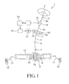
- an electric power steering system 1 includes: a steering shaft 3 connected to a steering member 2, such as a steering wheel, so as to be rotatable together with the steering member 2; an intermediate shaft 5 connected to the steering shaft 3 via a universal joint 4; and a pinion shaft 7 connected to the intermediate shaft 5 via a universal joint 6.
- the electric power steering system 1 further includes a rack bar 8 that has rack teeth 8a that mesh with pinion teeth 7a formed on the pinion shaft 7.
- the rack bar 8 functions as a steered shaft that extends in the lateral direction of an automobile.
- the pinion shaft 7 and the rack bar 8 constitute a steering mechanism 9 that is formed of a rack-and-pinion mechanism.
- the rack bar 8 is supported by a plurality of bearings (not shown) so as to be able to make a linear reciprocating motion, in a rack housing 10 that is fixed to a vehicle body. Two end portions of the rack bar 8 extend toward respective sides of the rack housing 10, and tie rods 11 are connected to the respective end portions of the rack bar 8.
- the tie rods 11 are connected to corresponding steered wheels 12 via corresponding knuckle arms (not shown).
- the steering shaft 3 is rotated in response to an operation of steering member 2, the rotation is converted into a linear motion of the rack bar 8 that extends in the lateral direction of the automobile, by the pinion teeth 7a and the rack teeth 8a, whereby the steered wheels 12 are steered.
- the steering shaft 3 is split into an input shaft 3a connected to the steering member 2 and an output shaft 3b connected to the pinion shaft 7.
- the input shaft 3a and the output shaft 3b are connected to each other via a torsion bar 13 so as to be rotatable relative to each other on the same axis.
- the torsion bar 13 is provided with a torque sensor 14 that detects a steering torque on the basis of the amount of relative rotational displacement between the input shaft 3a and the output shaft 3b.
- the result of torque detection obtained by the torque sensor 14 is provided to an electric control unit (ECU) 15.
- ECU electric control unit
- the ECU 15 executes drive control on an electric motor 17 for steering-assist, via a drive circuit 16, on the basis of the result of torque detection, the result of vehicle speed detection provided from a vehicle speed sensor (not shown), and the like.
- the rotation output from the electric motor 17 is transmitted to the pinion shaft 7 via a speed reducer 18 where the speed of rotation is reduced, and then is converted into a linear motion of the rack bar 8. In this way, steering is assisted.
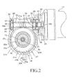
- the speed reducer 18 includes: a worm 19 serving as an input shaft that is driven to be rotated by the electric motor 17; and a worm wheel 20 that meshes with the worm 19 and that is connected to the output shaft 3b of the steering shaft 3 so as to be rotatable together with the output shaft 3b.
- the worm 19 and the worm wheel 20 are housed in a housing 21.
- the worm 19 is connected to a rotary shaft 22 of the electric motor 17 via a spline joint 23.
- the worm 19 is rotatably supported by two rolling bearings 24, 25 that are retained by the housing 21.
- Inner rings 26, 27 of the rolling bearings 24, 25 are fitted to corresponding narrowed portions of the worm 19.
- Outer rings 28, 29 of the rolling bearings 24, 25 are retained in bearing holding holes 30, 31 of the housing 21, respectively.
- the housing 21 has a tubular portion 21a that houses the worm 19.
- the outer ring 28 of the rolling bearing 24 that supports a first end portion 19a of the worm 19 is positioned by being brought into contact with a step portion 32 of the housing 21.
- the inner ring 26 of the rolling bearing 24 is brought into contact with a positioning step portion 33 of the worm 19, and is thereby restrained from moving toward a second end portion 19b of the worm 19.
- the inner ring 27 of the rolling bearing 25 supports a portion of the worm 19 that is near the second end portion 19b, which is a joint-side end portion of the worm 19.
- the inner ring 27 is brought into contact with a positioning step portion 34 of the worm 19, and is thereby restrained from moving toward the first end portion 19a.
- the outer ring 29 is urged toward the rolling bearing 24 by a screw member 35 for preload adjustment.
- the screw member 35 is screwed into a threaded hole 36 formed in the housing 21 so as to apply a preload to a pair of the rolling bearings 24, 25 and position the worm 19 in the axial direction of the worm 19.
- a locknut 37 is engaged with the screw member 35 in order to fix the position of the screw member 35 after the preload is adjusted.
- the worm wheel 20 includes: an annular metal core 20a that is coupled to the output shaft 3b so as to be rotatable together with the output shaft 3b; and a synthetic resin member 20c that surrounds the periphery of the metal core 20a and that has teeth 20b on its outer peripheral face portion.
- the metal core 20a is inserted in a molding die, for example, during resin molding of the synthetic resin member 20c. Through the resin molding performed with the metal core 20a inserted in the molding die, the metal core 20a and the synthetic resin member 20c are coupled to and integrated with each other.
- the output shaft 3b is supported so as to be rotatable relative to the housing 21, by a pair of rolling bearings (not shown) disposed such that the worm wheel 20 is interposed between the rolling bearings in the axial direction of the worm wheel 20.
- the housing 21 has a generally cylindrical portion 21b arranged with an outer peripheral space A having a constant width left between the generally cylindrical portion 21b and an outer periphery 20d of the worm wheel 20.
- the outer peripheral space A and a meshing section B, at which the worm 19 and the worm wheel 20 mesh with each other, are filled with grease G.
- the grease G is supplied into the outer peripheral space A such that the grease G is in contact with both tooth surfaces 20h of the teeth 20b of the worm wheel 20, each of which has a tooth tip 20e, tooth flanks 20f that are brought into contact with the worm 19, and a bottomland 20g, and an inner peripheral face 21c of the generally cylindrical portion 21b, which faces the worm wheel 20.
- the grease G supplied into the outer peripheral space A functions to prevent the grease G from being extruded from the meshing section B at which the worm 19 and the worm wheel 20 mesh with each other. If the grease G in the meshing section B is extruded, the grease G in the outer peripheral space A is supplied to the meshing section B with the rotations of the worm 19 and the worm wheel 20.
- the coefficient of sliding friction between the tooth surfaces of the worm 19 and the tooth surfaces of the worm wheel 20 can be appropriately reduced by lubrication provided by the grease oil films, and the oil films can buffer the impacts between the tooth surfaces, thereby suppressing generation of rattling noise.
- a width W 1 of the inner peripheral face of the generally cylindrical portion of the hoising 21b in the axial direction of the worm wheel 20 is substantially equal to a facewidth W 2 of the worm wheel 20. More specifically, the width W 1 is preferably less than or equal to 130% of the facewidth W 2 , and, more preferably less than or equal to 120% of the facewidth W 2 .
- Adoption of the aforementioned dimensional relationship reduces the volume of the outer peripheral space A. Therefore, it is possible to reduce the amount of grease required to fill the outer peripheral space A with the grease such that the grease is in contact with both the tooth surfaces 20h of the worm wheel 20 and the inner peripheral face 21c of the generally cylindrical portion 21b as described above. Furthermore, it is possible to prevent the grease supplied to the outer peripheral space A from moving onto the side faces of the worm wheel 20.
- the amount of grease supplied to the housing 21 is restricted to the minimum necessary amount, it is possible to prevent the situation where excess grease enters, for example, the rolling bearings 24, 25 incorporated in the speed reducer 18 and affects the performance of the speed reducer 18, and the situation where the grease leaks through gaps of the housing 21 and makes its surroundings dirty. Furthermore, restricting the amount of grease to the minimum necessary amount makes it possible to reduce the total amount of grease and to thereby reduce the cost.
- the width W 1 is preferably greater than or equal to 105% of the facewidth W 2 , within the aforementioned range.
- the filling width Wg which is a range where the grease supplied to the outer peripheral space A is present, in the axial direction of the worm wheel 20, is preferably less than or equal to the width W 1 of the inner peripheral face of the generally cylindrical portion of the hoising 21b and greater than or equal to the facewidth W 2 of the worm wheel 20.
- a shortest distance D 1 is the shortest distance between the worm wheel 20 and the inner peripheral face 21c of the generally cylindrical portion 21b in the radial direction of the worm wheel 20, that is, the distance between each tooth tip 20e of the worm wheel 20 and the inner peripheral face 21c of the generally cylindrical portion 21b.
- the shortest distance D 1 is preferably less than or equal to 1.6 mm.
- the shortest distance D 1 is preferably greater than or equal to 0.5 mm, within the aforementioned range.
- a low-viscosity grease of which the viscosity at 100°C and a sheering speed of 100 s -1 is less than or equal to 2 Pa•s is preferably employed.
- the aforementioned viscosity of the grease is a value measured by a rotary rheometer (MCR 301 manufactured by Anton Paar) with the use of a cone plate.
- the grease having a relatively low viscosity exhibits a fluidity higher than that of conventionally-used grease, for example, during operation of the speed reducer 18 incorporated in the electric power steering system 1. Therefore, if the grease is extruded from the meshing section B as the worm 19 and the worm wheel 20 rotate, the extruded grease or new grease promptly flows into the meshing section B with the rotations.
- the viscosity of the grease G at 100°C and a sheering speed of 100 s -1 is preferably greater than or equal to 0.3 Pa•s, within the aforementioned range.
- the viscosity of the grease is below the lower limit of the aforementioned range, the grease is excessively soft. Therefore, even if a sufficient amount of the grease is automatically supplied to the meshing section B due to its high fluidity, the grease flows out of a predetermined position due to vibration, centrifugal force caused by rotation, and other external forces. This may cause a possibility that grease oil films having a thickness sufficient to reduce friction and suppress rattling noise will not be formed.
- the viscosity of the grease is preferably greater than or equal to 0.5 Pa•s and less than or equal to 1.5 Pa•s, within the aforementioned range.
- Examples of base oils for the grease G include one or more kinds of synthetic oils, such as synthetic hydrocarbon oils, more specifically, poly- ⁇ -olefin oils (PAO), silicone oils, fluorine oils, ester oils, and ether oils, and mineral oils. Specifically, synthetic hydrocarbon oils are preferable.
- Examples of thickeners include one or more kinds of various thickeners including soap-based thickeners, urea-based thickeners, organic thickeners, and inorganic thickeners.
- soap-based thickeners include one or more kinds of: metal soap type thickeners, such as aluminum soap, calcium soap, lithium soap, and sodium soap; mixed base soap type thickeners, such as lithium-calcium soap, and sodium-calcium soap; complex type thickeners, such as aluminum complexes, calcium complexes, lithium complexes, and sodium complexes.
- metal soap type thickeners such as aluminum soap, calcium soap, lithium soap, and sodium soap
- mixed base soap type thickeners such as lithium-calcium soap, and sodium-calcium soap
- complex type thickeners such as aluminum complexes, calcium complexes, lithium complexes, and sodium complexes.
- Examples of the urea-based thickeners include polyurea.
- Examples of the organic thickeners include one or more kinds of polytetrafluoroethylene (PTFE), and sodium terephthalate.
- Examples of the inorganic thickeners include one or more kinds of bentonite, graphite, and silica gel.
- additives selected from: solid lubricants such as fluorine resins (PTFE, etc.), molybdenum disulfide, graphite, and polyolefin-based waxes (including amides and the like); phosphorus-based or sulfur-based extreme-pressure additives; antioxidants such as tributyl phenol, and methyl phenol; rust preventives; metal deactivators; viscosity index improvers; and oiliness improvers.
- solid lubricants such as fluorine resins (PTFE, etc.), molybdenum disulfide, graphite, and polyolefin-based waxes (including amides and the like); phosphorus-based or sulfur-based extreme-pressure additives; antioxidants such as tributyl phenol, and methyl phenol; rust preventives; metal deactivators; viscosity index improvers; and oiliness improvers.
- the amount of the grease G supplied to the housing 21 may be set to a value within such an appropriate range that there are not caused a problem that excess grease enters, for example, the rolling bearings 24, 25 incorporated in the speed reducer 18 and affects the performance of the speed reducer 18 and a problem that the grease leaks through gaps of the housing 21 and makes its surroundings dirty as described above.
- the aforementioned low-viscosity grease of which the viscosity at 100°C and a sheering speed of 100 s -1 is less than or equal to 2 Pa•s has high fluidity and is therefore likely to cause the aforementioned problems.
- the filling ratio when the entire space inside the housing 21 is filled with the grease is expressed by 100% and the filling ratio when there is no grease in the housing 21 is expressed by 0%, the filling ratio is preferably set to a value greater than or equal to 9% and less than or equal to 22%.
- the state where the filling ratio is 100% means a state where the outer peripheral space A inside the housing 21, the meshing section B and the tubular portion 21 a of the housing 21 are entirely filled with the grease G with no clearance left within the housing 21. If the filling ratio is below the lower limit of the aforementioned range, there is a possibility that the effect of reducing the coefficient of sliding friction between the tooth surfaces of the worm 19 and the tooth surfaces of the worm wheel 20 and the effect of buffering the impacts between the tooth surfaces to suppress generation of rattling noise, which are to be produced by supplying the grease, will no longer be obtained.
- the filling ratio exceeds the upper limit of the aforementioned range, there is a possibility that excess grease will enter, for example, the rolling bearings 24, 25 incorporated in the speed reducer 18 and affect the performance of the speed reducer 18, or a possibility that the grease will leak through gaps of the housing 21 and make its surroundings dirty.
- the invention is not limited to the embodiment illustrated in FIG. 1 to FIG. 3 .
- the structure of the speed reducer according to the invention may be applied to speed reducers for systems other than electric power steering systems.
- the invention may be implemented in various modified embodiments within the scope of the invention defined in the appended claims.
- the speed reducer 18 described below was prepared.
- the speed reducer 18 has the internal structure shown in FIG. 2 .
- the width W 1 of the inner peripheral face of the generally cylindrical portion of the hoising in the axial direction of the worm wheel 20 is 130% of the facewidth W 2 of the worm wheel 20.
- the shortest distance D 1 in the radial direction of the worm wheel 20 between the worm wheel 20 and the inner peripheral face 21c of the generally cylindrical portion 21b of the housing 21 is 1.4 mm.
- the prepared speed reducer 18 was incorporated to obtain the electric power steering system 1 as illustrated in FIG. 1 .
- Grease of which the viscosity at 100°C and a sheering speed of 100 s -1 is 1.0 Pa•s was used as the grease G.
- the grease G was supplied only to the meshing section B, where the worm 19 and the worm wheel 20 mesh with each other, and the outer peripheral space A within the housing 21 such that, in the outer peripheral space A, the grease G is in contact with both the tooth surfaces 20h of the worm wheel 20 and the inner peripheral face 21c of the generally cylindrical portion 21b.
- the filling ratio of the grease G was set to 9%.
- the filling width Wg of the grease G was set to 100% of the facewidth W 2 of the worm wheel 20.
- the same grease G as that used in the first example was supplied to the housing 21 of the speed reducer 18 of the same electric power steering system 1 as that used in the first example, so that only the meshing section B, where the worm 19 and the worm wheel 20 mesh with each other, and the outer peripheral space A were filled with the grease G and, in the outer peripheral space A, the grease G was in contact with both the tooth surfaces 20h of the worm wheel 20 and the inner peripheral face 21c of the generally cylindrical portion 21b.
- the filling ratio of the grease G was set to 11 %.
- the filling width Wg of the grease G was set to 120% of the facewidth W 2 of the worm wheel 20.
- the same grease G as that used in the first example was supplied to the housing 21 of the speed reducer 18 of the same electric power steering system 1 as that used in the first example, so that only the meshing section B, where the worm 19 and the worm wheel 20 mesh with each other, and the outer peripheral space A were filled with the grease G and, in the outer peripheral space A, the grease G was in contact with both the tooth surfaces 20h of the worm wheel 20 and the inner peripheral face 21c of the generally cylindrical portion 21b.
- the filling ratio of the grease G was set to 22%.
- the filling width Wg of the grease G was set to 130% of the facewidth W 2 of the worm wheel 20.
- the speed reducer 18 of the same electric power steering system 1 as that used in the first example was used, but no grease was supplied to the housing 21.
- the filling ratio was 0%.
- the same grease G as that used in the first example was supplied to the housing 21 of the speed reducer 18 of the same electric power steering system 1 as that used in the first example, so that only the meshing section B, where the worm 19 and the worm wheel 20 mesh with each other, and the outer peripheral space A were filled with the grease G and, in the outer peripheral space A, the grease G was in contact with only the tooth surfaces 20h of the worm wheel 20.
- the filling ratio of the grease G was set to 2%.
- the same grease G as that used in the first example was supplied to the housing 21 of the speed reducer 18 of the same electric power steering system 1 as that used in the first example, so that only the outer peripheral space A was filled with the grease G and, in the outer peripheral space A, the grease G was in contact with only the inner peripheral face 21c of the generally cylindrical portion 21b.
- the filling ratio of the grease G was set to 4%.
- the filling width Wg of the grease G on the inner peripheral face 21c was set to 100% of the facewidth W 2 of the worm wheel 20.
- the same grease G as that used in the first example was supplied to the housing 21 of the speed reducer 18 of the same electric power steering system 1 as that used in the first example, so that only the meshing section B, where the worm 19 and the worm wheel 20 mesh with each other, and the outer peripheral space A were filled with the grease G and, in the outer peripheral space A, the grease G was in contact with only the tooth surfaces 20h of the worm wheel 20.
- the filling ratio of the grease G was set to 4%.
- the same grease G as that used in the first example was supplied to the housing 21 of the speed reducer 18 of the same electric power steering system 1 as that used in the first example, so that the entire space inside the housing 21 is filled with the grease G with no clearance left in the housing 21.
- the filling ratio of the grease G was set to 100%.
- the filling width Wg of the grease G was set to 130% of the facewidth W 2 of the worm wheel 20.
- the amplitude of vibration was measured by a method described below, and the magnitude of rattling noise was evaluated.
- the amplitude of vibration of the housing 21 caused by inputting vibration into the electric power steering system 1 from the tie rods 11 was measured.
- the magnitudes of rattling noise in the examples and the comparative examples were evaluated by the amplitudes of vibration expressed in percentage using the amplitude of vibration in the first comparative example as 100%.
- the presence or absence of leakage of the grease from the housing 21 was checked after the electric power steering system 1 was operated continuously for 42 hours under an environment of 100°C.
- the vibration amplitudes in the second to fourth comparative examples shown in Table 2 indicate that, when the grease was supplied to the outer peripheral space A so as to be in contact with the tooth surfaces 20h of the worm wheel 20 or the inner peripheral face 21c of the generally cylindrical portion 21b of the housing 21, generation of rattling noise was suppressed more reliably than in the first comparative example where no grease was supplied to the outer peripheral space A, but the effect was not sufficient.
- the vibration amplitude in the fifth comparative example indicates that, when the entire space in the housing 21 was filled with the grease with no clearance left within the housing 21, rattling noise was reduced to a level lower than that in each of the second to fourth comparative examples. However, in the fifth comparative example, leakage of grease was confirmed.
- the results in the first to third examples indicate that, when the grease filling ratio is greater than or equal to 9% and less than or equal to 22%, the vibration amplitude is small, and therefore the range from 9% to 22% is an appropriate range.
- the results in the first to third examples indicate that the ratio of the width W 1 of the outer peripheral space A to the facewidth W 2 is preferably be less than or equal to 130%.
- the result in the second example indicates that the vibration amplitude is smallest when the ratio of the filling width W g to the facewidth W 2 is at or around 120%.
- the results in the first to third examples indicate that the vibration amplitude is small when the shortest distance D 1 between the worm wheel 20 and the inner peripheral face 21c of the generally cylindrical portion 21 b of the housing 21 in the radial direction of the worm wheel 20 is 1.4 mm.
Landscapes
- Engineering & Computer Science (AREA)
- General Engineering & Computer Science (AREA)
- Mechanical Engineering (AREA)
- Chemical & Material Sciences (AREA)
- Combustion & Propulsion (AREA)
- Transportation (AREA)
- Power Steering Mechanism (AREA)
- General Details Of Gearings (AREA)
- Gear Transmission (AREA)
- Lubricants (AREA)
Abstract
Description
- The invention relates to a speed reducer and an electric power steering system that includes the speed reducer.
- Generally, in an electric power steering system, torque output from a steering-assist electric motor is amplified by reducing, with the use of a speed reducer, the speed of rotation transmitted from a rotary shaft of the electric motor. The amplified torque is transmitted to a steering mechanism, such as a rack-and-pinion mechanism, whereby torque assist is provided to an operation of the steering mechanism caused in response to a driver's steering operation. As the speed reducer, for example, a worm speed reducer constructed of a worm and a worm wheel that mesh with each other is used. The worm speed reducer includes a housing that houses the worm and the worm wheel, and is supplied with grease.
- The grease supplied into the speed reducer lies between tooth surfaces of the worm and tooth surfaces of the worm wheel, and forms oil films. The oil films formed by the grease functions to assist sliding between the tooth surfaces caused by the rotation of the worm due to the rotation of the rotary shaft of the electric motor and the rotation of the worm wheel due to the rotation of the worm, and functions to buffer impacts that occur between the tooth surfaces due to the rotations, thereby reducing rattling noise generated by the impacts. Therefore, supplying the speed reducer with the grease makes it possible to reduce steering torque of the electric power steering system and suppress rattling noise, thereby improving a driver's steering feel.
- The characteristics, such as a viscosity, of the grease are appropriately adjusted by taking into account, for example, the use of the grease and the usage environment of the grease. Commonly-used grease has a low fluidity, and therefore is easily extruded from a meshing section at which the worm and the worm wheel mesh with each other, due to a sliding motion of the worm itself caused by the rotations of the worm and the worm wheel. Once the grease is extruded from the meshing section due to the sliding motion, the extruded grease accumulates around the meshing section, and does not automatically return to the meshing section.
- Therefore, the meshing section runs out of grease, so that the effect of assisting sliding between tooth surfaces and the effect of buffering impacts between the tooth surfaces, which are produced by the grease oil films, are no longer obtained. Therefore, for example, in the case of an electric power steering system, the steering torque increases and rattling noise is generated. As a result, the driver's steering feel deteriorates. In order to cope with the above-described phenomenon, not only the meshing section but also, for example, substantially the entire space inside the housing is filled with grease.
- In some cases, there is provided a structure for circulating the grease extruded from the meshing section to return the grease to the meshing section as the worm and the worm wheel rotate. Refer to, for example, Japanese Patent Application Publication No.
2005-69476 JP 2005-69476 A 2006-76443 JP 2006-76443 A 2007-303487 JP 2007-303487 A - In order to fill substantially the entire space inside the housing with grease as described above, a large amount of grease is required. If a large amount of grease is present in the speed reducer, the grease may enter, for example, a rolling bearing and affect the performance of the speed reducer, or the grease may leak through gaps of the housing and make its surroundings dirty. Furthermore, an increase in the amount of grease results in a cost increase.
- Even if a large amount of grease is supplied, the grease is extruded from the meshing section with the rotations. After the grease is extruded from the meshing section, the meshing section is not automatically replenished with new grease because the conventional grease has a low fluidity as described above. Therefore, it is not possible to prevent the meshing section from running out of the grease. On other hand, when the mechanism for circulating the grease within, for example, the housing is provided, the grease is automatically returned by the mechanism to the meshing section at which the worm and the worm wheel mesh with each other, as the worm and the worm wheel rotate. Therefore, it is possible to reduce the total amount of grease that is supplied into the housing, and to prevent the meshing section from running out of the grease.
- However, provision of the mechanism complicates the structures of the housing, the speed reducer and the like, leading to increases in the costs of the speed reducer, the electric power steering system and the like.
- One object of the invention is to provide a speed reducer configured such that shortage of grease is reliably prevented just by supplying a small amount of grease, without the need for complication of the overall structure, and to provide an electric power steering system that includes the speed reducer.
- A speed reducer according to an aspect of the invention includes: a worm; a worm wheel that meshes with the worm; and a housing that houses the worm and the worm wheel. In the speed reducer, the housing has a generally cylindrical portion arranged with a space having a constant width left between the generally cylindrical portion and an outer periphery of the worm wheel. Only a meshing section where the worm and the worm wheel mesh with each other and the space between the outer periphery of the worm wheel and the generally cylindrical portion are filled with grease. The grease in the space is in contact with both tooth surfaces of the worm wheel and an inner peripheral face of the generally cylindrical portion, the inner peripheral face facing the worm wheel.
- With the configuration in the above-described aspect, the grease supplied to the space between the outer periphery of the worm wheel and the generally cylindrical portion of the housing (hereinafter, referred to as "outer peripheral space" where appropriate) so as to be in contact with both the tooth surfaces of the worm wheel and the inner peripheral face of the generally cylindrical portion, which faces the worm wheel, functions to prevent the grease from being extruded from the meshing section, where the worm and the worm wheel mesh with each other, due to a sliding motion of the worm itself caused by the rotations of the worm and the worm wheel. Even if the grease is extruded from the meshing section, the grease in the outer peripheral space is supplied to the meshing section with the rotations.
- Therefore, it is possible to prevent the meshing section from running out of the grease, just by supplying the grease only to the meshing section, at which the worm and the worm wheel mesh with each other, and the outer peripheral space between the outer periphery of the worm wheel and the generally cylindrical portion, without filling substantially the entire space inside the housing with a large amount of grease, and, further, without the need for complication of the structure of the speed reducer.
- Therefore, the coefficient of sliding friction between the tooth surfaces of the worm and the tooth surfaces of the worm wheel can be reduced by lubrication provided by the grease oil films, and the oil films can buffer the impacts between the tooth surfaces, thereby suppressing generation of rattling noise. In the speed reducer according to the above-described aspect, a width of the outer peripheral space in an axial direction of the worm wheel may be substantially equal to a facewidth of the worm wheel.
- In the speed reducer according to the above-described aspect, in the space, a shortest distance between the worm wheel and the inner peripheral face of the generally cylindrical portion in a radial direction of the worm wheel may be less than or equal to 1.6 mm. With the configuration described above, the volume of the outer peripheral space is reduced. Therefore, it is possible to reduce the amount of grease required to fill the outer peripheral space with the grease such that the grease is in contact with both the tooth surfaces of the worm wheel and the inner peripheral face of the generally cylindrical portion.
- Furthermore, it is possible to prevent the grease in the outer peripheral space from moving onto the side faces of the worm wheel. Therefore, it is possible to appropriately maintain the aforementioned effects while restricting the amount of grease supplied to the housing to the minimum necessary amount. Because the amount of grease supplied to the housing is restricted to the minimum necessary amount, it is possible to prevent the situation where excess grease enters rolling bearings incorporated in the speed reducer and affects the performance of the speed reducer, and the situation where the grease leaks through gaps of the housing and makes its surroundings dirty. Furthermore, restricting the amount of grease to the minimum necessary amount makes it possible to reduce the total amount of grease and to thereby reduce the cost.
- In the speed reducer according to the above-described aspect, grease of which the viscosity at 100°C and a sheering speed of 100 s-1 is less than or equal to 2 Pa•s may be used as the grease. With this configuration, even if the grease is extruded from the meshing section, where the worm and the worm wheel mesh with each other, due to the sliding motion of the worm itself caused by the rotations of the worm and the worm wheel, the extruded grease or new grease promptly flows into the meshing section with the rotations because the above-described grease having a relatively low viscosity exhibits a fluidity higher than that of conventionally-used grease.
- Therefore, it is possible to maintain the state where the meshing section, where the worm and the worm wheel mesh with each other, is always filled with a sufficient amount of grease to lubricate the meshing section.
- The speed reducer according to the above-described aspect may be incorporated into an electric power steering system. With this configuration, because the steering torque is small and generation of rattling noise is suppressed, it is possible to provide an electric power steering system which provides excellent operation feel.
- The foregoing and further features and advantages of the invention will become apparent from the following description of example embodiments with reference to the accompanying drawings, wherein like numerals are used to represent like elements and wherein:
-
FIG. 1 is a view schematically illustrating an example of an electric power steering system according to an embodiment of the invention; -
FIG. 2 is a sectional view illustrating an example of a speed reducer according to the embodiment; and -
FIG. 3 is an enlarged sectional view illustrating part of a worm wheel and a housing of the speed reducer. - Hereinafter, embodiments of the invention will be described with reference to the accompanying drawings. Referring to
FIG. 1 , an electric power steering system 1 according to an embodiment of the invention includes: a steering shaft 3 connected to asteering member 2, such as a steering wheel, so as to be rotatable together with thesteering member 2; anintermediate shaft 5 connected to the steering shaft 3 via auniversal joint 4; and apinion shaft 7 connected to theintermediate shaft 5 via auniversal joint 6. The electric power steering system 1 further includes a rack bar 8 that hasrack teeth 8a that mesh withpinion teeth 7a formed on thepinion shaft 7. The rack bar 8 functions as a steered shaft that extends in the lateral direction of an automobile. - The
pinion shaft 7 and the rack bar 8 constitute a steering mechanism 9 that is formed of a rack-and-pinion mechanism. The rack bar 8 is supported by a plurality of bearings (not shown) so as to be able to make a linear reciprocating motion, in arack housing 10 that is fixed to a vehicle body. Two end portions of the rack bar 8 extend toward respective sides of therack housing 10, andtie rods 11 are connected to the respective end portions of the rack bar 8. - The
tie rods 11 are connected to corresponding steeredwheels 12 via corresponding knuckle arms (not shown). When the steering shaft 3 is rotated in response to an operation of steeringmember 2, the rotation is converted into a linear motion of the rack bar 8 that extends in the lateral direction of the automobile, by thepinion teeth 7a and therack teeth 8a, whereby the steeredwheels 12 are steered. - The steering shaft 3 is split into an
input shaft 3a connected to the steeringmember 2 and anoutput shaft 3b connected to thepinion shaft 7. Theinput shaft 3a and theoutput shaft 3b are connected to each other via atorsion bar 13 so as to be rotatable relative to each other on the same axis. Furthermore, thetorsion bar 13 is provided with atorque sensor 14 that detects a steering torque on the basis of the amount of relative rotational displacement between theinput shaft 3a and theoutput shaft 3b. The result of torque detection obtained by thetorque sensor 14 is provided to an electric control unit (ECU) 15. - The
ECU 15 executes drive control on anelectric motor 17 for steering-assist, via adrive circuit 16, on the basis of the result of torque detection, the result of vehicle speed detection provided from a vehicle speed sensor (not shown), and the like. The rotation output from theelectric motor 17 is transmitted to thepinion shaft 7 via aspeed reducer 18 where the speed of rotation is reduced, and then is converted into a linear motion of the rack bar 8. In this way, steering is assisted. - Referring to
FIG. 1 andFIG. 2 , thespeed reducer 18 includes: aworm 19 serving as an input shaft that is driven to be rotated by theelectric motor 17; and aworm wheel 20 that meshes with theworm 19 and that is connected to theoutput shaft 3b of the steering shaft 3 so as to be rotatable together with theoutput shaft 3b. Theworm 19 and theworm wheel 20 are housed in ahousing 21. - The
worm 19 is connected to arotary shaft 22 of theelectric motor 17 via a spline joint 23. Theworm 19 is rotatably supported by two rollingbearings housing 21. Inner rings 26, 27 of the rollingbearings worm 19. Outer rings 28, 29 of the rollingbearings holes housing 21, respectively. Thehousing 21 has atubular portion 21a that houses theworm 19. - The
outer ring 28 of the rollingbearing 24 that supports afirst end portion 19a of theworm 19 is positioned by being brought into contact with astep portion 32 of thehousing 21. Theinner ring 26 of the rollingbearing 24 is brought into contact with apositioning step portion 33 of theworm 19, and is thereby restrained from moving toward asecond end portion 19b of theworm 19. Theinner ring 27 of the rollingbearing 25 supports a portion of theworm 19 that is near thesecond end portion 19b, which is a joint-side end portion of theworm 19. Theinner ring 27 is brought into contact with apositioning step portion 34 of theworm 19, and is thereby restrained from moving toward thefirst end portion 19a. - The
outer ring 29 is urged toward the rollingbearing 24 by ascrew member 35 for preload adjustment. Thescrew member 35 is screwed into a threadedhole 36 formed in thehousing 21 so as to apply a preload to a pair of the rollingbearings worm 19 in the axial direction of theworm 19. Alocknut 37 is engaged with thescrew member 35 in order to fix the position of thescrew member 35 after the preload is adjusted. - The
worm wheel 20 includes: anannular metal core 20a that is coupled to theoutput shaft 3b so as to be rotatable together with theoutput shaft 3b; and a synthetic resin member 20c that surrounds the periphery of themetal core 20a and that hasteeth 20b on its outer peripheral face portion. Themetal core 20a is inserted in a molding die, for example, during resin molding of the synthetic resin member 20c. Through the resin molding performed with themetal core 20a inserted in the molding die, themetal core 20a and the synthetic resin member 20c are coupled to and integrated with each other. Theoutput shaft 3b is supported so as to be rotatable relative to thehousing 21, by a pair of rolling bearings (not shown) disposed such that theworm wheel 20 is interposed between the rolling bearings in the axial direction of theworm wheel 20. - Referring to
FIG. 2 andFIG. 3 , thehousing 21 has a generallycylindrical portion 21b arranged with an outer peripheral space A having a constant width left between the generallycylindrical portion 21b and anouter periphery 20d of theworm wheel 20. In the present embodiment of the invention, only the outer peripheral space A and a meshing section B, at which theworm 19 and theworm wheel 20 mesh with each other, are filled with grease G. As indicated by hatching with dashed lines inFIG. 3 , the grease G is supplied into the outer peripheral space A such that the grease G is in contact with bothtooth surfaces 20h of theteeth 20b of theworm wheel 20, each of which has atooth tip 20e, tooth flanks 20f that are brought into contact with theworm 19, and abottomland 20g, and an innerperipheral face 21c of the generallycylindrical portion 21b, which faces theworm wheel 20. - The grease G supplied into the outer peripheral space A functions to prevent the grease G from being extruded from the meshing section B at which the
worm 19 and theworm wheel 20 mesh with each other. If the grease G in the meshing section B is extruded, the grease G in the outer peripheral space A is supplied to the meshing section B with the rotations of theworm 19 and theworm wheel 20.
Therefore, it is possible to prevent the meshing section B from running out of the grease and to maintain the state where a sufficient amount of grease to lubricate the meshing section B is always present at the meshing section B, just by supplying the grease G only to the meshing section B, at which theworm 19 and theworm wheel 20 mesh with each other, and the outer peripheral space A between theworm wheel 20 and the generallycylindrical portion 21b, without filling substantially the entire space inside thehousing 21 with a large amount of grease, and, further, without the need for complication of the structure of thespeed reducer 18. - Therefore, the coefficient of sliding friction between the tooth surfaces of the
worm 19 and the tooth surfaces of theworm wheel 20 can be appropriately reduced by lubrication provided by the grease oil films, and the oil films can buffer the impacts between the tooth surfaces, thereby suppressing generation of rattling noise. - Referring to
FIG. 3 , preferably, a width W1 of the inner peripheral face of the generally cylindrical portion of the hoising 21b in the axial direction of theworm wheel 20 is substantially equal to a facewidth W2 of theworm wheel 20. More specifically, the width W1 is preferably less than or equal to 130% of the facewidth W2, and, more preferably less than or equal to 120% of the facewidth W2. - Adoption of the aforementioned dimensional relationship reduces the volume of the outer peripheral space A. Therefore, it is possible to reduce the amount of grease required to fill the outer peripheral space A with the grease such that the grease is in contact with both the tooth surfaces 20h of the
worm wheel 20 and the innerperipheral face 21c of the generallycylindrical portion 21b as described above. Furthermore, it is possible to prevent the grease supplied to the outer peripheral space A from moving onto the side faces of theworm wheel 20. - Because the amount of grease supplied to the
housing 21 is restricted to the minimum necessary amount, it is possible to prevent the situation where excess grease enters, for example, the rollingbearings speed reducer 18 and affects the performance of thespeed reducer 18, and the situation where the grease leaks through gaps of thehousing 21 and makes its surroundings dirty. Furthermore, restricting the amount of grease to the minimum necessary amount makes it possible to reduce the total amount of grease and to thereby reduce the cost. - In order to allow the
worm wheel 20 to smoothly rotate relative to thehousing 21, the width W1 is preferably greater than or equal to 105% of the facewidth W2, within the aforementioned range. The filling width Wg, which is a range where the grease supplied to the outer peripheral space A is present, in the axial direction of theworm wheel 20, is preferably less than or equal to the width W1 of the inner peripheral face of the generally cylindrical portion of thehoising 21b and greater than or equal to the facewidth W2 of theworm wheel 20. - In the outer peripheral space A, a shortest distance D1 is the shortest distance between the
worm wheel 20 and the innerperipheral face 21c of the generallycylindrical portion 21b in the radial direction of theworm wheel 20, that is, the distance between eachtooth tip 20e of theworm wheel 20 and the innerperipheral face 21c of the generallycylindrical portion 21b. The shortest distance D1 is preferably less than or equal to 1.6 mm. By adopting the aforementioned dimensional relationship, the grease present in the outer peripheral space A is allowed to function as a wall, so that the grease is prevented from being extruded from the meshing section B where theworm 19 and theworm wheel 20 mesh with each other. Furthermore, because the volume of the outer peripheral space A is small, the amount of grease required to fill the space A with the grease is reduced. - In order to ensure the required amount of grease, the shortest distance D1 is preferably greater than or equal to 0.5 mm, within the aforementioned range.
- As the grease G, a low-viscosity grease of which the viscosity at 100°C and a sheering speed of 100 s-1 is less than or equal to 2 Pa•s is preferably employed. The aforementioned viscosity of the grease is a value measured by a rotary rheometer (MCR 301 manufactured by Anton Paar) with the use of a cone plate.
- If the grease having a relatively low viscosity is used, the grease exhibits a fluidity higher than that of conventionally-used grease, for example, during operation of the
speed reducer 18 incorporated in the electric power steering system 1. Therefore, if the grease is extruded from the meshing section B as theworm 19 and theworm wheel 20 rotate, the extruded grease or new grease promptly flows into the meshing section B with the rotations. - Therefore, it is possible to maintain the state where the meshing section B, where the
worm 19 and theworm wheel 20 mesh with each other, is always filled with a sufficient amount of grease to lubricate the meshing section B. Therefore, the coefficient of sliding friction between the tooth surfaces of theworm 19 and the tooth surfaces of theworm wheel 20 can be appropriately reduced by lubrication provided by the grease oil films, and the oil films can buffer the impacts between the tooth surfaces, thereby suppressing generation of rattling noise. - The viscosity of the grease G at 100°C and a sheering speed of 100 s-1 is preferably greater than or equal to 0.3 Pa•s, within the aforementioned range.
- If the viscosity of the grease is below the lower limit of the aforementioned range, the grease is excessively soft. Therefore, even if a sufficient amount of the grease is automatically supplied to the meshing section B due to its high fluidity, the grease flows out of a predetermined position due to vibration, centrifugal force caused by rotation, and other external forces. This may cause a possibility that grease oil films having a thickness sufficient to reduce friction and suppress rattling noise will not be formed. On the basis of the above-described facts, the viscosity of the grease is preferably greater than or equal to 0.5 Pa•s and less than or equal to 1.5 Pa•s, within the aforementioned range.
- Examples of base oils for the grease G include one or more kinds of synthetic oils, such as synthetic hydrocarbon oils, more specifically, poly-α-olefin oils (PAO), silicone oils, fluorine oils, ester oils, and ether oils, and mineral oils. Specifically, synthetic hydrocarbon oils are preferable. Examples of thickeners include one or more kinds of various thickeners including soap-based thickeners, urea-based thickeners, organic thickeners, and inorganic thickeners.
- Examples of the soap-based thickeners include one or more kinds of: metal soap type thickeners, such as aluminum soap, calcium soap, lithium soap, and sodium soap; mixed base soap type thickeners, such as lithium-calcium soap, and sodium-calcium soap; complex type thickeners, such as aluminum complexes, calcium complexes, lithium complexes, and sodium complexes.
- Examples of the urea-based thickeners include polyurea. Examples of the organic thickeners include one or more kinds of polytetrafluoroethylene (PTFE), and sodium terephthalate. Examples of the inorganic thickeners include one or more kinds of bentonite, graphite, and silica gel. One or more kinds of additives selected from: solid lubricants such as fluorine resins (PTFE, etc.), molybdenum disulfide, graphite, and polyolefin-based waxes (including amides and the like); phosphorus-based or sulfur-based extreme-pressure additives; antioxidants such as tributyl phenol, and methyl phenol; rust preventives; metal deactivators; viscosity index improvers; and oiliness improvers.
- The amount of the grease G supplied to the
housing 21 may be set to a value within such an appropriate range that there are not caused a problem that excess grease enters, for example, the rollingbearings speed reducer 18 and affects the performance of thespeed reducer 18 and a problem that the grease leaks through gaps of thehousing 21 and makes its surroundings dirty as described above. For example, the aforementioned low-viscosity grease of which the viscosity at 100°C and a sheering speed of 100 s-1 is less than or equal to 2 Pa•s has high fluidity and is therefore likely to cause the aforementioned problems. Therefore, if the filling ratio when the entire space inside thehousing 21 is filled with the grease is expressed by 100% and the filling ratio when there is no grease in thehousing 21 is expressed by 0%, the filling ratio is preferably set to a value greater than or equal to 9% and less than or equal to 22%. - The state where the filling ratio is 100% means a state where the outer peripheral space A inside the
housing 21, the meshing section B and thetubular portion 21 a of thehousing 21 are entirely filled with the grease G with no clearance left within thehousing 21. If the filling ratio is below the lower limit of the aforementioned range, there is a possibility that the effect of reducing the coefficient of sliding friction between the tooth surfaces of theworm 19 and the tooth surfaces of theworm wheel 20 and the effect of buffering the impacts between the tooth surfaces to suppress generation of rattling noise, which are to be produced by supplying the grease, will no longer be obtained. - On the other hand, if the filling ratio exceeds the upper limit of the aforementioned range, there is a possibility that excess grease will enter, for example, the rolling
bearings speed reducer 18 and affect the performance of thespeed reducer 18, or a possibility that the grease will leak through gaps of thehousing 21 and make its surroundings dirty.
Note that, the invention is not limited to the embodiment illustrated inFIG. 1 to FIG. 3 . For example, the structure of the speed reducer according to the invention may be applied to speed reducers for systems other than electric power steering systems. Furthermore, the invention may be implemented in various modified embodiments within the scope of the invention defined in the appended claims. - Configurations of a plurality of examples in which the embodiment of the invention is applied to electric power steering systems will be described below. In a first example, the
speed reducer 18 described below was prepared. Thespeed reducer 18 has the internal structure shown inFIG. 2 . In thespeed reducer 18, the width W1 of the inner peripheral face of the generally cylindrical portion of the hoising in the axial direction of theworm wheel 20 is 130% of the facewidth W2 of theworm wheel 20. In the outer peripheral space A, the shortest distance D1 in the radial direction of theworm wheel 20 between theworm wheel 20 and the innerperipheral face 21c of the generallycylindrical portion 21b of thehousing 21 is 1.4 mm. Theprepared speed reducer 18 was incorporated to obtain the electric power steering system 1 as illustrated inFIG. 1 . - Grease of which the viscosity at 100°C and a sheering speed of 100 s-1 is 1.0 Pa•s was used as the grease G. The grease G was supplied only to the meshing section B, where the
worm 19 and theworm wheel 20 mesh with each other, and the outer peripheral space A within thehousing 21 such that, in the outer peripheral space A, the grease G is in contact with both the tooth surfaces 20h of theworm wheel 20 and the innerperipheral face 21c of the generallycylindrical portion 21b. The filling ratio of the grease G was set to 9%. Furthermore, the filling width Wg of the grease G was set to 100% of the facewidth W2 of theworm wheel 20. - In a second example, the same grease G as that used in the first example was supplied to the
housing 21 of thespeed reducer 18 of the same electric power steering system 1 as that used in the first example, so that only the meshing section B, where theworm 19 and theworm wheel 20 mesh with each other, and the outer peripheral space A were filled with the grease G and, in the outer peripheral space A, the grease G was in contact with both the tooth surfaces 20h of theworm wheel 20 and the innerperipheral face 21c of the generallycylindrical portion 21b. The filling ratio of the grease G was set to 11 %. The filling width Wg of the grease G was set to 120% of the facewidth W2 of theworm wheel 20. - In a third example, the same grease G as that used in the first example was supplied to the
housing 21 of thespeed reducer 18 of the same electric power steering system 1 as that used in the first example, so that only the meshing section B, where theworm 19 and theworm wheel 20 mesh with each other, and the outer peripheral space A were filled with the grease G and, in the outer peripheral space A, the grease G was in contact with both the tooth surfaces 20h of theworm wheel 20 and the innerperipheral face 21c of the generallycylindrical portion 21b. The filling ratio of the grease G was set to 22%. The filling width Wg of the grease G was set to 130% of the facewidth W2 of theworm wheel 20. - In order to confirm the effectiveness of the foregoing examples, comparative examples having other configurations were set. Experiments were conducted under both the conditions of the comparative examples and the conditions of the foregoing examples to confirm superiority of the foregoing examples.
- In a first comparative example, the
speed reducer 18 of the same electric power steering system 1 as that used in the first example was used, but no grease was supplied to thehousing 21. The filling ratio was 0%. In a second comparative example, the same grease G as that used in the first example was supplied to thehousing 21 of thespeed reducer 18 of the same electric power steering system 1 as that used in the first example, so that only the meshing section B, where theworm 19 and theworm wheel 20 mesh with each other, and the outer peripheral space A were filled with the grease G and, in the outer peripheral space A, the grease G was in contact with only the tooth surfaces 20h of theworm wheel 20. The filling ratio of the grease G was set to 2%. - In a third comparative example, the same grease G as that used in the first example was supplied to the
housing 21 of thespeed reducer 18 of the same electric power steering system 1 as that used in the first example, so that only the outer peripheral space A was filled with the grease G and, in the outer peripheral space A, the grease G was in contact with only the innerperipheral face 21c of the generallycylindrical portion 21b. The filling ratio of the grease G was set to 4%. The filling width Wg of the grease G on the innerperipheral face 21c was set to 100% of the facewidth W2 of theworm wheel 20. - In a fourth comparative example, the same grease G as that used in the first example was supplied to the
housing 21 of thespeed reducer 18 of the same electric power steering system 1 as that used in the first example, so that only the meshing section B, where theworm 19 and theworm wheel 20 mesh with each other, and the outer peripheral space A were filled with the grease G and, in the outer peripheral space A, the grease G was in contact with only the tooth surfaces 20h of theworm wheel 20. The filling ratio of the grease G was set to 4%. - In a fifth comparative example, the same grease G as that used in the first example was supplied to the
housing 21 of thespeed reducer 18 of the same electric power steering system 1 as that used in the first example, so that the entire space inside thehousing 21 is filled with the grease G with no clearance left in thehousing 21. The filling ratio of the grease G was set to 100%. The filling width Wg of the grease G was set to 130% of the facewidth W2 of theworm wheel 20. - In each of the examples and the comparative examples, the amplitude of vibration was measured by a method described below, and the magnitude of rattling noise was evaluated. The amplitude of vibration of the
housing 21 caused by inputting vibration into the electric power steering system 1 from thetie rods 11 was measured. The magnitudes of rattling noise in the examples and the comparative examples were evaluated by the amplitudes of vibration expressed in percentage using the amplitude of vibration in the first comparative example as 100%. - The presence or absence of leakage of the grease from the
housing 21 was checked after the electric power steering system 1 was operated continuously for 42 hours under an environment of 100°C. - The conditions set for the first to third examples and the first to fifth comparative examples are shown in Table 1, and results of evaluation are shown in Table 2.
Table 1 W1 (%) D1 (mm) Presence or absence of grease at meshing section B Presence or absence of grease at tooth surfaces 20hPresence or absence of grease at inner peripheral face 21cFilling ratio (%) Filling width Wg (%) Viscosity (Pa•s) First example 130 1.4 Present Present Present 9 100 1.0 Second example 130 1.4 Present Present Present 11 120 1.0 Third example 130 1.4 Present Present Present 22 130 1.0 First comparative example 130 1.4 Absent Absent Absent 0 - - Second comparative example 130 1.4 Present Present Absent 2 - 1.0 Third comparative example 130 1.4 Absent Absent Present 4 100 1.0 Fourth comparative example 130 1.4 Present Present Absent 4 - 1.0 Fifth comparative example 130 1.4 Present Present Present 100 130 1.0 Table 2 Vibration amplitude (%) Grease leakage First example 51.7 Absent Second example 47.3 Absent Third example 49.8 Absent First comparative example 100 Absent Second comparative example 66.2 Absent Third comparative example 68.2 Absent Fourth comparative example 64.7 Absent Fifth comparative example 53.7 Present - The vibration amplitudes in the second to fourth comparative examples shown in Table 2 indicate that, when the grease was supplied to the outer peripheral space A so as to be in contact with the tooth surfaces 20h of the
worm wheel 20 or the innerperipheral face 21c of the generallycylindrical portion 21b of thehousing 21, generation of rattling noise was suppressed more reliably than in the first comparative example where no grease was supplied to the outer peripheral space A, but the effect was not sufficient. The vibration amplitude in the fifth comparative example indicates that, when the entire space in thehousing 21 was filled with the grease with no clearance left within thehousing 21, rattling noise was reduced to a level lower than that in each of the second to fourth comparative examples. However, in the fifth comparative example, leakage of grease was confirmed. - On the other hand, the results of observations on the vibration amplitude and presence or absence of grease leakage in the first to third examples in Table 2 indicate that it is possible to considerably reduce rattling noise without causing leakage of the grease, by filling only the meshing section B and the outer peripheral space A, instead of the entire space inside the
housing 21, with the grease such that the grease is in contact with both the tooth surfaces 20h of theworm wheel 20 and the innerperipheral face 21c of the generallycylindrical portion 21b of thehousing 21 in the outer peripheral space A. - The results in the first to third examples indicate that, when the grease filling ratio is greater than or equal to 9% and less than or equal to 22%, the vibration amplitude is small, and therefore the range from 9% to 22% is an appropriate range. The results in the first to third examples indicate that the ratio of the width W1 of the outer peripheral space A to the facewidth W2 is preferably be less than or equal to 130%. In particular, the result in the second example indicates that the vibration amplitude is smallest when the ratio of the filling width Wg to the facewidth W2 is at or around 120%.
The results in the first to third examples indicate that the vibration amplitude is small when the shortest distance D1 between theworm wheel 20 and the innerperipheral face 21c of the generallycylindrical portion 21 b of thehousing 21 in the radial direction of theworm wheel 20 is 1.4 mm.
Claims (5)
- A speed reducer, comprising:a worm;a worm wheel that meshes with the worm; anda housing that houses the worm and the worm wheel,wherein the housing has a generally cylindrical portion arranged with a space having a constant width left between the generally cylindrical portion and an outer periphery of the worm wheel,wherein only a meshing section where the worm and the worm wheel mesh with each other and the space between the outer periphery of the worm wheel and the generally cylindrical portion are filled with grease, andwherein the grease in the space is in contact with both a tooth surface of the worm wheel and an inner peripheral face of the generally cylindrical portion, the inner peripheral face facing the worm wheel.
- The speed reducer according to claim 1, wherein a width of the inner peripheral face of the generally cylindrical portion of the housing in an axial direction of the worm wheel is substantially equal to a facewidth of the worm wheel.
- The speed reducer according to claim 1 or 2, wherein, in the space, a shortest distance between the worm wheel and the inner peripheral face of the generally cylindrical portion in a radial direction of the worm wheel is less than or equal to 1.6 mm.
- The speed reducer according to any one of claims 1 to 3, wherein a viscosity of the grease at 100°C and a sheering speed of 100 s-1 is less than or equal to 2 Pa•s.
- An electric power steering system, comprising the speed reducer according to any one of claims 1 to 4.
Applications Claiming Priority (1)
| Application Number | Priority Date | Filing Date | Title |
|---|---|---|---|
| JP2012227084A JP5988097B2 (en) | 2012-10-12 | 2012-10-12 | Reducer and electric power steering device |
Publications (2)
| Publication Number | Publication Date |
|---|---|
| EP2719926A1 true EP2719926A1 (en) | 2014-04-16 |
| EP2719926B1 EP2719926B1 (en) | 2018-06-27 |
Family
ID=49356233
Family Applications (1)
| Application Number | Title | Priority Date | Filing Date |
|---|---|---|---|
| EP13188040.3A Active EP2719926B1 (en) | 2012-10-12 | 2013-10-10 | Speed reducer and electric power steering system |
Country Status (4)
| Country | Link |
|---|---|
| US (1) | US9061698B2 (en) |
| EP (1) | EP2719926B1 (en) |
| JP (1) | JP5988097B2 (en) |
| CN (1) | CN103727216B (en) |
Cited By (1)
| Publication number | Priority date | Publication date | Assignee | Title |
|---|---|---|---|---|
| CN117408106A (en) * | 2023-10-17 | 2024-01-16 | 浙江大学 | A calculation method for gear tooth impact noise considering tooth surface lubrication |
Families Citing this family (7)
| Publication number | Priority date | Publication date | Assignee | Title |
|---|---|---|---|---|
| JP6544953B2 (en) * | 2014-05-29 | 2019-07-17 | 株式会社リコー | Image forming apparatus and grease composition |
| JP6527720B2 (en) | 2014-05-29 | 2019-06-05 | 株式会社リコー | Drive device, image forming apparatus and grease composition |
| JP6544952B2 (en) | 2014-05-29 | 2019-07-17 | 株式会社リコー | Drive device and image forming apparatus |
| DE102016008018B4 (en) * | 2016-07-04 | 2020-04-23 | AUMA Drives GmbH | transmission |
| JP6479741B2 (en) * | 2016-10-11 | 2019-03-06 | 株式会社椿本チエイン | Gear device |
| JP6848487B2 (en) * | 2017-01-31 | 2021-03-24 | コニカミノルタ株式会社 | Solid lubricant, solid lubricant coating device and image forming device |
| CN114576339A (en) * | 2022-03-01 | 2022-06-03 | 中车太原机车车辆有限公司 | Universal speed reducer of railway hopper car with vertical split structure and railway hopper car |
Citations (6)
| Publication number | Priority date | Publication date | Assignee | Title |
|---|---|---|---|---|
| JP2005069476A (en) | 2003-08-06 | 2005-03-17 | Nsk Ltd | Reduction gear mechanism and electric power steering device |
| JP2005176527A (en) * | 2003-12-12 | 2005-06-30 | Nsk Ltd | Electric actuator |
| JP2006076443A (en) | 2004-09-09 | 2006-03-23 | Nsk Ltd | Electric power steering device |
| JP2007303487A (en) | 2006-05-09 | 2007-11-22 | Nsk Ltd | Worm reducer and electric power steering device |
| JP2009248724A (en) * | 2008-04-04 | 2009-10-29 | Honda Motor Co Ltd | Electric power steering device |
| EP2489901A1 (en) * | 2011-02-16 | 2012-08-22 | Kayaba Industry Co., Ltd. | Worm reduction gear |
Family Cites Families (8)
| Publication number | Priority date | Publication date | Assignee | Title |
|---|---|---|---|---|
| JPH09169988A (en) * | 1995-12-20 | 1997-06-30 | Tonen Corp | Lubricating oil composition for reduction mechanism |
| DE602004028350D1 (en) * | 2003-03-19 | 2010-09-09 | Nsk Ltd | ELECTRIC POWER STEERING DEVICE AND RESIN WHEEL THEREFORE USED |
| DE112004000679T5 (en) * | 2003-06-25 | 2006-04-06 | Nsk Steering Systems Co., Ltd. | Electric power steering |
| JP4687226B2 (en) * | 2005-04-28 | 2011-05-25 | 株式会社ジェイテクト | Rolling device using lubricating grease composition and electric power steering device using this rolling device |
| JP2007002872A (en) * | 2005-06-21 | 2007-01-11 | Nsk Ltd | Steering shaft support bearing |
| JP2007196751A (en) * | 2006-01-24 | 2007-08-09 | Jtekt Corp | Electric power steering device |
| JP2007216917A (en) * | 2006-02-20 | 2007-08-30 | Jtekt Corp | Electric power steering device |
| JP5403989B2 (en) * | 2008-10-16 | 2014-01-29 | 株式会社ジェイテクト | Lubricant composition, speed reducer and electric power steering apparatus using the same |
-
2012
- 2012-10-12 JP JP2012227084A patent/JP5988097B2/en active Active
-
2013
- 2013-10-04 US US14/046,014 patent/US9061698B2/en active Active
- 2013-10-10 EP EP13188040.3A patent/EP2719926B1/en active Active
- 2013-10-10 CN CN201310470617.5A patent/CN103727216B/en active Active
Patent Citations (6)
| Publication number | Priority date | Publication date | Assignee | Title |
|---|---|---|---|---|
| JP2005069476A (en) | 2003-08-06 | 2005-03-17 | Nsk Ltd | Reduction gear mechanism and electric power steering device |
| JP2005176527A (en) * | 2003-12-12 | 2005-06-30 | Nsk Ltd | Electric actuator |
| JP2006076443A (en) | 2004-09-09 | 2006-03-23 | Nsk Ltd | Electric power steering device |
| JP2007303487A (en) | 2006-05-09 | 2007-11-22 | Nsk Ltd | Worm reducer and electric power steering device |
| JP2009248724A (en) * | 2008-04-04 | 2009-10-29 | Honda Motor Co Ltd | Electric power steering device |
| EP2489901A1 (en) * | 2011-02-16 | 2012-08-22 | Kayaba Industry Co., Ltd. | Worm reduction gear |
Cited By (2)
| Publication number | Priority date | Publication date | Assignee | Title |
|---|---|---|---|---|
| CN117408106A (en) * | 2023-10-17 | 2024-01-16 | 浙江大学 | A calculation method for gear tooth impact noise considering tooth surface lubrication |
| CN117408106B (en) * | 2023-10-17 | 2024-07-16 | 浙江大学 | A calculation method for gear tooth impact noise considering tooth surface lubrication |
Also Published As
| Publication number | Publication date |
|---|---|
| JP2014080985A (en) | 2014-05-08 |
| US20140102235A1 (en) | 2014-04-17 |
| CN103727216A (en) | 2014-04-16 |
| CN103727216B (en) | 2018-01-12 |
| US9061698B2 (en) | 2015-06-23 |
| EP2719926B1 (en) | 2018-06-27 |
| JP5988097B2 (en) | 2016-09-07 |
Similar Documents
| Publication | Publication Date | Title |
|---|---|---|
| EP2719926B1 (en) | Speed reducer and electric power steering system | |
| US9841090B2 (en) | Electric linear actuator | |
| EP1840193A2 (en) | Lubricant composition, expandable shaft, and steering system using the same | |
| CN102224058B (en) | Electric Power Steering | |
| JP2004162018A (en) | Lubricant composition, reduction gear using the same, and electric power steering device using the same | |
| JP4994030B2 (en) | Lubricant composition, speed reducer using the same, and electric power steering device using the same | |
| EP2682327A2 (en) | Electric power steering system | |
| JP2014122659A (en) | Speed reducer, and electric power steering device | |
| JP2007145952A (en) | Lubricant composition, speed reducer using the same, and electric power steering device using the same | |
| JP2016094159A (en) | Reduction gear and electric power steering device | |
| JP2014080991A (en) | Reduction gear, and electric power steering device | |
| JP2005133791A (en) | Reducer and electric power steering device using the same | |
| JP4140450B2 (en) | Reducer and electric power steering apparatus equipped with the same | |
| JP3847171B2 (en) | Reducer and electric power steering apparatus including the same | |
| JP4411511B2 (en) | Reducer and electric power steering device using the same | |
| WO2016104010A1 (en) | Grease composition and spline telescopic shaft | |
| JP2005329849A (en) | Electric power steering device | |
| EP4502116A1 (en) | Grease | |
| JP4406819B2 (en) | Reducer and electric power steering device using the same | |
| JP4702624B2 (en) | Reducer, electric power steering device and worm wheel | |
| JP4702623B2 (en) | Reducer, electric power steering device and worm | |
| CN205589299U (en) | Automobile steering device | |
| JP2004143263A (en) | Lubricant composition, reduction gear using the same, and electric power steering apparatus including the same | |
| JP2005133792A (en) | Reducer and electric power steering device using the same | |
| JP2008115297A (en) | Lubricant composition, reduction gear, and electric power steering device |
Legal Events
| Date | Code | Title | Description |
|---|---|---|---|
| PUAI | Public reference made under article 153(3) epc to a published international application that has entered the european phase |
Free format text: ORIGINAL CODE: 0009012 |
|
| AK | Designated contracting states |
Kind code of ref document: A1 Designated state(s): AL AT BE BG CH CY CZ DE DK EE ES FI FR GB GR HR HU IE IS IT LI LT LU LV MC MK MT NL NO PL PT RO RS SE SI SK SM TR |
|
| AX | Request for extension of the european patent |
Extension state: BA ME |
|
| 17P | Request for examination filed |
Effective date: 20141016 |
|
| RBV | Designated contracting states (corrected) |
Designated state(s): AL AT BE BG CH CY CZ DE DK EE ES FI FR GB GR HR HU IE IS IT LI LT LU LV MC MK MT NL NO PL PT RO RS SE SI SK SM TR |
|
| 17Q | First examination report despatched |
Effective date: 20150217 |
|
| GRAP | Despatch of communication of intention to grant a patent |
Free format text: ORIGINAL CODE: EPIDOSNIGR1 |
|
| INTG | Intention to grant announced |
Effective date: 20180118 |
|
| GRAS | Grant fee paid |
Free format text: ORIGINAL CODE: EPIDOSNIGR3 |
|
| GRAA | (expected) grant |
Free format text: ORIGINAL CODE: 0009210 |
|
| AK | Designated contracting states |
Kind code of ref document: B1 Designated state(s): AL AT BE BG CH CY CZ DE DK EE ES FI FR GB GR HR HU IE IS IT LI LT LU LV MC MK MT NL NO PL PT RO RS SE SI SK SM TR |
|
| REG | Reference to a national code |
Ref country code: GB Ref legal event code: FG4D |
|
| REG | Reference to a national code |
Ref country code: AT Ref legal event code: REF Ref document number: 1012631 Country of ref document: AT Kind code of ref document: T Effective date: 20180715 |
|
| REG | Reference to a national code |
Ref country code: IE Ref legal event code: FG4D |
|
| REG | Reference to a national code |
Ref country code: DE Ref legal event code: R096 Ref document number: 602013039351 Country of ref document: DE |
|
| REG | Reference to a national code |
Ref country code: FR Ref legal event code: PLFP Year of fee payment: 6 |
|
| PG25 | Lapsed in a contracting state [announced via postgrant information from national office to epo] |
Ref country code: SE Free format text: LAPSE BECAUSE OF FAILURE TO SUBMIT A TRANSLATION OF THE DESCRIPTION OR TO PAY THE FEE WITHIN THE PRESCRIBED TIME-LIMIT Effective date: 20180627 Ref country code: NO Free format text: LAPSE BECAUSE OF FAILURE TO SUBMIT A TRANSLATION OF THE DESCRIPTION OR TO PAY THE FEE WITHIN THE PRESCRIBED TIME-LIMIT Effective date: 20180927 Ref country code: BG Free format text: LAPSE BECAUSE OF FAILURE TO SUBMIT A TRANSLATION OF THE DESCRIPTION OR TO PAY THE FEE WITHIN THE PRESCRIBED TIME-LIMIT Effective date: 20180927 Ref country code: FI Free format text: LAPSE BECAUSE OF FAILURE TO SUBMIT A TRANSLATION OF THE DESCRIPTION OR TO PAY THE FEE WITHIN THE PRESCRIBED TIME-LIMIT Effective date: 20180627 Ref country code: LT Free format text: LAPSE BECAUSE OF FAILURE TO SUBMIT A TRANSLATION OF THE DESCRIPTION OR TO PAY THE FEE WITHIN THE PRESCRIBED TIME-LIMIT Effective date: 20180627 |
|
| REG | Reference to a national code |
Ref country code: NL Ref legal event code: MP Effective date: 20180627 |
|
| REG | Reference to a national code |
Ref country code: LT Ref legal event code: MG4D |
|
| PG25 | Lapsed in a contracting state [announced via postgrant information from national office to epo] |
Ref country code: RS Free format text: LAPSE BECAUSE OF FAILURE TO SUBMIT A TRANSLATION OF THE DESCRIPTION OR TO PAY THE FEE WITHIN THE PRESCRIBED TIME-LIMIT Effective date: 20180627 Ref country code: HR Free format text: LAPSE BECAUSE OF FAILURE TO SUBMIT A TRANSLATION OF THE DESCRIPTION OR TO PAY THE FEE WITHIN THE PRESCRIBED TIME-LIMIT Effective date: 20180627 Ref country code: LV Free format text: LAPSE BECAUSE OF FAILURE TO SUBMIT A TRANSLATION OF THE DESCRIPTION OR TO PAY THE FEE WITHIN THE PRESCRIBED TIME-LIMIT Effective date: 20180627 Ref country code: GR Free format text: LAPSE BECAUSE OF FAILURE TO SUBMIT A TRANSLATION OF THE DESCRIPTION OR TO PAY THE FEE WITHIN THE PRESCRIBED TIME-LIMIT Effective date: 20180928 |
|
| REG | Reference to a national code |
Ref country code: AT Ref legal event code: MK05 Ref document number: 1012631 Country of ref document: AT Kind code of ref document: T Effective date: 20180627 |
|
| PG25 | Lapsed in a contracting state [announced via postgrant information from national office to epo] |
Ref country code: NL Free format text: LAPSE BECAUSE OF FAILURE TO SUBMIT A TRANSLATION OF THE DESCRIPTION OR TO PAY THE FEE WITHIN THE PRESCRIBED TIME-LIMIT Effective date: 20180627 |
|
| PG25 | Lapsed in a contracting state [announced via postgrant information from national office to epo] |
Ref country code: CZ Free format text: LAPSE BECAUSE OF FAILURE TO SUBMIT A TRANSLATION OF THE DESCRIPTION OR TO PAY THE FEE WITHIN THE PRESCRIBED TIME-LIMIT Effective date: 20180627 Ref country code: AT Free format text: LAPSE BECAUSE OF FAILURE TO SUBMIT A TRANSLATION OF THE DESCRIPTION OR TO PAY THE FEE WITHIN THE PRESCRIBED TIME-LIMIT Effective date: 20180627 Ref country code: RO Free format text: LAPSE BECAUSE OF FAILURE TO SUBMIT A TRANSLATION OF THE DESCRIPTION OR TO PAY THE FEE WITHIN THE PRESCRIBED TIME-LIMIT Effective date: 20180627 Ref country code: IS Free format text: LAPSE BECAUSE OF FAILURE TO SUBMIT A TRANSLATION OF THE DESCRIPTION OR TO PAY THE FEE WITHIN THE PRESCRIBED TIME-LIMIT Effective date: 20181027 Ref country code: EE Free format text: LAPSE BECAUSE OF FAILURE TO SUBMIT A TRANSLATION OF THE DESCRIPTION OR TO PAY THE FEE WITHIN THE PRESCRIBED TIME-LIMIT Effective date: 20180627 Ref country code: PL Free format text: LAPSE BECAUSE OF FAILURE TO SUBMIT A TRANSLATION OF THE DESCRIPTION OR TO PAY THE FEE WITHIN THE PRESCRIBED TIME-LIMIT Effective date: 20180627 Ref country code: SK Free format text: LAPSE BECAUSE OF FAILURE TO SUBMIT A TRANSLATION OF THE DESCRIPTION OR TO PAY THE FEE WITHIN THE PRESCRIBED TIME-LIMIT Effective date: 20180627 |
|
| PG25 | Lapsed in a contracting state [announced via postgrant information from national office to epo] |
Ref country code: ES Free format text: LAPSE BECAUSE OF FAILURE TO SUBMIT A TRANSLATION OF THE DESCRIPTION OR TO PAY THE FEE WITHIN THE PRESCRIBED TIME-LIMIT Effective date: 20180627 Ref country code: IT Free format text: LAPSE BECAUSE OF FAILURE TO SUBMIT A TRANSLATION OF THE DESCRIPTION OR TO PAY THE FEE WITHIN THE PRESCRIBED TIME-LIMIT Effective date: 20180627 Ref country code: SM Free format text: LAPSE BECAUSE OF FAILURE TO SUBMIT A TRANSLATION OF THE DESCRIPTION OR TO PAY THE FEE WITHIN THE PRESCRIBED TIME-LIMIT Effective date: 20180627 |
|
| REG | Reference to a national code |
Ref country code: DE Ref legal event code: R097 Ref document number: 602013039351 Country of ref document: DE |
|
| PLBE | No opposition filed within time limit |
Free format text: ORIGINAL CODE: 0009261 |
|
| STAA | Information on the status of an ep patent application or granted ep patent |
Free format text: STATUS: NO OPPOSITION FILED WITHIN TIME LIMIT |
|
| PG25 | Lapsed in a contracting state [announced via postgrant information from national office to epo] |
Ref country code: DK Free format text: LAPSE BECAUSE OF FAILURE TO SUBMIT A TRANSLATION OF THE DESCRIPTION OR TO PAY THE FEE WITHIN THE PRESCRIBED TIME-LIMIT Effective date: 20180627 |
|
| REG | Reference to a national code |
Ref country code: CH Ref legal event code: PL |
|
| 26N | No opposition filed |
Effective date: 20190328 |
|
| GBPC | Gb: european patent ceased through non-payment of renewal fee |
Effective date: 20181010 |
|
| REG | Reference to a national code |
Ref country code: BE Ref legal event code: MM Effective date: 20181031 |
|
| PG25 | Lapsed in a contracting state [announced via postgrant information from national office to epo] |
Ref country code: MC Free format text: LAPSE BECAUSE OF FAILURE TO SUBMIT A TRANSLATION OF THE DESCRIPTION OR TO PAY THE FEE WITHIN THE PRESCRIBED TIME-LIMIT Effective date: 20180627 Ref country code: LU Free format text: LAPSE BECAUSE OF NON-PAYMENT OF DUE FEES Effective date: 20181010 |
|
| REG | Reference to a national code |
Ref country code: IE Ref legal event code: MM4A |
|
| PG25 | Lapsed in a contracting state [announced via postgrant information from national office to epo] |
Ref country code: LI Free format text: LAPSE BECAUSE OF NON-PAYMENT OF DUE FEES Effective date: 20181031 Ref country code: BE Free format text: LAPSE BECAUSE OF NON-PAYMENT OF DUE FEES Effective date: 20181031 Ref country code: SI Free format text: LAPSE BECAUSE OF FAILURE TO SUBMIT A TRANSLATION OF THE DESCRIPTION OR TO PAY THE FEE WITHIN THE PRESCRIBED TIME-LIMIT Effective date: 20180627 Ref country code: CH Free format text: LAPSE BECAUSE OF NON-PAYMENT OF DUE FEES Effective date: 20181031 |
|
| PG25 | Lapsed in a contracting state [announced via postgrant information from national office to epo] |
Ref country code: IE Free format text: LAPSE BECAUSE OF NON-PAYMENT OF DUE FEES Effective date: 20181010 Ref country code: GB Free format text: LAPSE BECAUSE OF NON-PAYMENT OF DUE FEES Effective date: 20181010 |
|
| PG25 | Lapsed in a contracting state [announced via postgrant information from national office to epo] |
Ref country code: AL Free format text: LAPSE BECAUSE OF FAILURE TO SUBMIT A TRANSLATION OF THE DESCRIPTION OR TO PAY THE FEE WITHIN THE PRESCRIBED TIME-LIMIT Effective date: 20180627 |
|
| PG25 | Lapsed in a contracting state [announced via postgrant information from national office to epo] |
Ref country code: MT Free format text: LAPSE BECAUSE OF NON-PAYMENT OF DUE FEES Effective date: 20181010 |
|
| PG25 | Lapsed in a contracting state [announced via postgrant information from national office to epo] |
Ref country code: TR Free format text: LAPSE BECAUSE OF FAILURE TO SUBMIT A TRANSLATION OF THE DESCRIPTION OR TO PAY THE FEE WITHIN THE PRESCRIBED TIME-LIMIT Effective date: 20180627 |
|
| PG25 | Lapsed in a contracting state [announced via postgrant information from national office to epo] |
Ref country code: PT Free format text: LAPSE BECAUSE OF FAILURE TO SUBMIT A TRANSLATION OF THE DESCRIPTION OR TO PAY THE FEE WITHIN THE PRESCRIBED TIME-LIMIT Effective date: 20180627 |
|
| PG25 | Lapsed in a contracting state [announced via postgrant information from national office to epo] |
Ref country code: CY Free format text: LAPSE BECAUSE OF FAILURE TO SUBMIT A TRANSLATION OF THE DESCRIPTION OR TO PAY THE FEE WITHIN THE PRESCRIBED TIME-LIMIT Effective date: 20180627 Ref country code: MK Free format text: LAPSE BECAUSE OF NON-PAYMENT OF DUE FEES Effective date: 20180627 Ref country code: HU Free format text: LAPSE BECAUSE OF FAILURE TO SUBMIT A TRANSLATION OF THE DESCRIPTION OR TO PAY THE FEE WITHIN THE PRESCRIBED TIME-LIMIT; INVALID AB INITIO Effective date: 20131010 |
|
| PGFP | Annual fee paid to national office [announced via postgrant information from national office to epo] |
Ref country code: FR Payment date: 20250908 Year of fee payment: 13 |
|
| PGFP | Annual fee paid to national office [announced via postgrant information from national office to epo] |
Ref country code: DE Payment date: 20250902 Year of fee payment: 13 |