EP2719913A1 - Automatic clutch control device - Google Patents
Automatic clutch control device Download PDFInfo
- Publication number
- EP2719913A1 EP2719913A1 EP11867196.5A EP11867196A EP2719913A1 EP 2719913 A1 EP2719913 A1 EP 2719913A1 EP 11867196 A EP11867196 A EP 11867196A EP 2719913 A1 EP2719913 A1 EP 2719913A1
- Authority
- EP
- European Patent Office
- Prior art keywords
- revolution
- clutch
- opening degree
- detection
- automatic clutch
- Prior art date
- Legal status (The legal status is an assumption and is not a legal conclusion. Google has not performed a legal analysis and makes no representation as to the accuracy of the status listed.)
- Withdrawn
Links
- 238000001514 detection method Methods 0.000 claims abstract description 131
- 238000012937 correction Methods 0.000 claims abstract description 119
- 238000012545 processing Methods 0.000 claims description 60
- 230000005540 biological transmission Effects 0.000 claims description 40
- 238000004364 calculation method Methods 0.000 claims description 33
- 230000001133 acceleration Effects 0.000 claims description 16
- 230000008878 coupling Effects 0.000 claims description 10
- 238000010168 coupling process Methods 0.000 claims description 10
- 238000005859 coupling reaction Methods 0.000 claims description 10
- 230000006870 function Effects 0.000 description 14
- 238000010586 diagram Methods 0.000 description 9
- 238000000034 method Methods 0.000 description 6
- 230000007423 decrease Effects 0.000 description 4
- 230000007935 neutral effect Effects 0.000 description 4
- 239000003921 oil Substances 0.000 description 4
- 230000000994 depressogenic effect Effects 0.000 description 3
- 230000000881 depressing effect Effects 0.000 description 2
- 230000000694 effects Effects 0.000 description 2
- 230000005284 excitation Effects 0.000 description 2
- 238000002474 experimental method Methods 0.000 description 2
- 230000007246 mechanism Effects 0.000 description 2
- 230000004048 modification Effects 0.000 description 2
- 238000012986 modification Methods 0.000 description 2
- 238000004088 simulation Methods 0.000 description 2
- 238000012546 transfer Methods 0.000 description 2
- 230000008859 change Effects 0.000 description 1
- 230000009194 climbing Effects 0.000 description 1
- 238000002485 combustion reaction Methods 0.000 description 1
- 230000003111 delayed effect Effects 0.000 description 1
- 230000009977 dual effect Effects 0.000 description 1
- 239000010720 hydraulic oil Substances 0.000 description 1
- 230000002093 peripheral effect Effects 0.000 description 1
- 230000008569 process Effects 0.000 description 1
Images





Classifications
-
- F—MECHANICAL ENGINEERING; LIGHTING; HEATING; WEAPONS; BLASTING
- F16—ENGINEERING ELEMENTS AND UNITS; GENERAL MEASURES FOR PRODUCING AND MAINTAINING EFFECTIVE FUNCTIONING OF MACHINES OR INSTALLATIONS; THERMAL INSULATION IN GENERAL
- F16D—COUPLINGS FOR TRANSMITTING ROTATION; CLUTCHES; BRAKES
- F16D48/00—External control of clutches
- F16D48/06—Control by electric or electronic means, e.g. of fluid pressure
- F16D48/08—Regulating clutch take-up on starting
-
- F—MECHANICAL ENGINEERING; LIGHTING; HEATING; WEAPONS; BLASTING
- F16—ENGINEERING ELEMENTS AND UNITS; GENERAL MEASURES FOR PRODUCING AND MAINTAINING EFFECTIVE FUNCTIONING OF MACHINES OR INSTALLATIONS; THERMAL INSULATION IN GENERAL
- F16D—COUPLINGS FOR TRANSMITTING ROTATION; CLUTCHES; BRAKES
- F16D2500/00—External control of clutches by electric or electronic means
- F16D2500/30—Signal inputs
- F16D2500/306—Signal inputs from the engine
- F16D2500/3067—Speed of the engine
-
- F—MECHANICAL ENGINEERING; LIGHTING; HEATING; WEAPONS; BLASTING
- F16—ENGINEERING ELEMENTS AND UNITS; GENERAL MEASURES FOR PRODUCING AND MAINTAINING EFFECTIVE FUNCTIONING OF MACHINES OR INSTALLATIONS; THERMAL INSULATION IN GENERAL
- F16D—COUPLINGS FOR TRANSMITTING ROTATION; CLUTCHES; BRAKES
- F16D2500/00—External control of clutches by electric or electronic means
- F16D2500/50—Problem to be solved by the control system
- F16D2500/502—Relating the clutch
- F16D2500/50224—Drive-off
-
- F—MECHANICAL ENGINEERING; LIGHTING; HEATING; WEAPONS; BLASTING
- F16—ENGINEERING ELEMENTS AND UNITS; GENERAL MEASURES FOR PRODUCING AND MAINTAINING EFFECTIVE FUNCTIONING OF MACHINES OR INSTALLATIONS; THERMAL INSULATION IN GENERAL
- F16D—COUPLINGS FOR TRANSMITTING ROTATION; CLUTCHES; BRAKES
- F16D2500/00—External control of clutches by electric or electronic means
- F16D2500/50—Problem to be solved by the control system
- F16D2500/502—Relating the clutch
- F16D2500/50227—Control of clutch to control engine
-
- F—MECHANICAL ENGINEERING; LIGHTING; HEATING; WEAPONS; BLASTING
- F16—ENGINEERING ELEMENTS AND UNITS; GENERAL MEASURES FOR PRODUCING AND MAINTAINING EFFECTIVE FUNCTIONING OF MACHINES OR INSTALLATIONS; THERMAL INSULATION IN GENERAL
- F16D—COUPLINGS FOR TRANSMITTING ROTATION; CLUTCHES; BRAKES
- F16D2500/00—External control of clutches by electric or electronic means
- F16D2500/50—Problem to be solved by the control system
- F16D2500/504—Relating the engine
-
- F—MECHANICAL ENGINEERING; LIGHTING; HEATING; WEAPONS; BLASTING
- F16—ENGINEERING ELEMENTS AND UNITS; GENERAL MEASURES FOR PRODUCING AND MAINTAINING EFFECTIVE FUNCTIONING OF MACHINES OR INSTALLATIONS; THERMAL INSULATION IN GENERAL
- F16D—COUPLINGS FOR TRANSMITTING ROTATION; CLUTCHES; BRAKES
- F16D2500/00—External control of clutches by electric or electronic means
- F16D2500/70—Details about the implementation of the control system
- F16D2500/704—Output parameters from the control unit; Target parameters to be controlled
- F16D2500/70422—Clutch parameters
- F16D2500/70438—From the output shaft
- F16D2500/7044—Output shaft torque
-
- F—MECHANICAL ENGINEERING; LIGHTING; HEATING; WEAPONS; BLASTING
- F16—ENGINEERING ELEMENTS AND UNITS; GENERAL MEASURES FOR PRODUCING AND MAINTAINING EFFECTIVE FUNCTIONING OF MACHINES OR INSTALLATIONS; THERMAL INSULATION IN GENERAL
- F16D—COUPLINGS FOR TRANSMITTING ROTATION; CLUTCHES; BRAKES
- F16D2500/00—External control of clutches by electric or electronic means
- F16D2500/70—Details about the implementation of the control system
- F16D2500/704—Output parameters from the control unit; Target parameters to be controlled
- F16D2500/70452—Engine parameters
- F16D2500/70454—Engine speed
-
- F—MECHANICAL ENGINEERING; LIGHTING; HEATING; WEAPONS; BLASTING
- F16—ENGINEERING ELEMENTS AND UNITS; GENERAL MEASURES FOR PRODUCING AND MAINTAINING EFFECTIVE FUNCTIONING OF MACHINES OR INSTALLATIONS; THERMAL INSULATION IN GENERAL
- F16D—COUPLINGS FOR TRANSMITTING ROTATION; CLUTCHES; BRAKES
- F16D2500/00—External control of clutches by electric or electronic means
- F16D2500/70—Details about the implementation of the control system
- F16D2500/706—Strategy of control
- F16D2500/70605—Adaptive correction; Modifying control system parameters, e.g. gains, constants, look-up tables
Definitions
- the present invention relates to an automatic clutch control apparatus for an automatic clutch that is configured to alternate between a coupling state and a decoupling state by changing a clutch stroke and transmit a torque between an engine and a transmission in the coupling state, so as to correct a torque characteristic curve showing a relation between the clutch stroke and the clutch torque when a vehicle advances.
- the clutch control apparatus in which the temperature of a clutch disc is assumed, and the clutch stroke is corrected based on the assumed temperature (see Patent Document 1).
- the clutch torque desirably is controlled corresponding to thermal expansion of constitutional components of the clutch.
- Patent Document 1 Japanese Unexamined Patent Application Publication No. 2008-185217 .
- the thermal expansion amount of the clutch disc is assumed larger than the actual thermal expansion amount of the clutch disc, which causes the actual clutch torque having a value lower than the desired clutch torque.
- the present invention has been achieved in view of the above circumstances to solve the technical problems, and it is an object of the present invention to provide an automatic clutch control apparatus that appropriately corrects a torque characteristic curve.
- an automatic clutch control apparatus is configured as follows.
- an automatic clutch control apparatus may be such that an automatic clutch is configured to alternate between a coupling state and a decoupling state by changing a clutch stroke and transmit a torque between an engine and a transmission in the coupling state, so as to correct a torque characteristic curve showing a relation between the clutch stroke and the clutch torque when a vehicle advances
- the automatic clutch control apparatus includes an opening degree detection means for detecting at least one out of a throttle opening degree and an accelerator opening degree, a reference setting means for setting a reference revolution that is an engine revolution that outputs an engine torque required for the vehicle to advance, based on at least one out of the throttle opening degree and the accelerator opening degree detected by the opening degree detection means, a revolution detection means for detecting an engine revolution, and a correction means for correcting the clutch stroke instructed to the automatic clutch by correcting the torque characteristic curve in such a manner that the detection revolution that is the engine revolution detected by the revolution detection means is brought close to the reference revolution set by the reference setting means.
- the automatic clutch control apparatus of the above-described configuration at least one out of the throttle opening degree and the accelerator opening degree is detected, and the reference revolution that is the engine revolution that outputs the engine torque required for the vehicle to advance is set based on at least one out of the throttle opening degree and the accelerator opening degree to be detected. Then, the engine revolution is detected, and the clutch stroke instructed to the automatic clutch is corrected by correcting the torque characteristic curve in such a manner that the detection revolution that is the engine revolution to be detected is brought close to the reference revolution to be set, so that the torque characteristic curve is appropriately corrected.
- the setting of the reference revolution having an appropriate value leads to the setting of the engine revolution that outputs the engine torque required for the vehicle to advance as the reference revolution.
- the torque characteristic curve is corrected in such a manner that the detection revolution that is the engine revolution to be detected is brought close to the reference revolution to be set, and the torque characteristic curve is corrected to output the engine torque required for the vehicle to advance, so that the torque characteristic curve is appropriately corrected.
- the automatic clutch control apparatus be such that the reference setting means sets the engine revolution that outputs the engine torque to accelerate the vehicle at a uniform acceleration corresponding to at least one out of the throttle opening degree and the accelerator opening degree detected by the opening degree detection means as the reference revolution in a period during which the automatic clutch operates from an engagement start point to a full engagement point.
- the engine revolution that outputs engine torque to accelerate the vehicle at the uniform acceleration corresponding to at least one out of the throttle opening degree and the accelerator opening degree to be detected is set as the reference revolution in the period during which the automatic clutch operates from the engagement start point to the full engagement point, so that the engine revolution having a more appropriate value is provided.
- the vehicle advances, and the vehicle is accelerated at the uniform acceleration corresponding to at least one out of the throttle opening degree and the accelerator opening degree in the period during which the automatic clutch operates from the engagement start point to the full engagement point, the vehicle advances smoothly. Accordingly, thus, the engine revolution that outputs the engine torque to accelerate the vehicle at the uniform acceleration corresponding to at least one out of the throttle opening degree and the accelerator opening degree is set as the reference revolution, so that the engine revolution having a more appropriate value is set.
- the automatic clutch control apparatus further include a revolution storing means for storing in advance the reference revolution corresponding to at least one out of the throttle opening degree and the accelerator opening degree, the revolution setting means sets the reference revolution by reading out, from the revolution storing means, the reference revolution corresponding to at least one out of the throttle opening degree and the accelerator opening degree detected by the opening degree detection means.
- the reference revolution is stored in the revolution storing means in advance, corresponding to at least one out of the throttle opening degree and the accelerator opening degree, and the reference revolution is set by reading out, from the revolution storing means, the reference revolution corresponding to at least one out of the throttle opening degree and the accelerator opening degree to be detected, so that appropriate reference revolution is set with a simple configuration.
- the automatic clutch control apparatus be such that the revolution setting means carries out at least one out of "delay processing” and “moderating processing” with respect to the reference revolution read out from the revolution storing means so as to set the reference revolution.
- the automatic clutch control apparatus be such that the correction means corrects a position at the full engagement point on the torque characteristic curve in the stroke direction so as to correct the clutch stroke instructed to the automatic clutch.
- the position at the full engagement point on the torque characteristic curve is corrected in the stroke direction, which leads to the correction of the clutch stroke instructed to the automatic clutch, so that the clutch stroke is corrected with a simple configuration.
- the automatic clutch control apparatus be such that, when the detection revolution is larger than the reference revolution, the correction means corrects the position at the full engagement point on the torque characteristic curve to a side to which the automatic clutch is coupled, and when the detection revolution is smaller than the reference revolution, the correction means corrects the position at the full engagement point on the torque characteristic curve to a side from which the automatic clutch is decoupled.
- the position at the full engagement point on the torque characteristic curve is corrected to the side to which the automatic clutch is coupled, and the detection revolution decreases so as to come close to the reference revolution, so that the clutch stroke is appropriately corrected.
- the detection revolution is smaller than the reference revolution, the position at the full engagement point on the torque characteristic curve is corrected to the side from which the automatic clutch is decoupled, and the detection revolution increases so as to come close to the reference revolution, so that the clutch stroke is appropriately corrected.
- the automatic clutch control apparatus further include a correction amount calculation means for obtaining a correction amount of the clutch stroke instructed to the automatic clutch based on a difference that is subtraction of the reference revolution from the detection revolution, the correction means corrects the position at the full engagement point on the torque characteristic curve in the stroke direction only by the correction amount obtained by the correction amount calculation means.
- the correction amount of the clutch stroke instructed to the automatic clutch is obtained based on the difference that is the subtraction of the reference revolution from the detection revolution, and the position at the full engagement point on the torque characteristic curve is corrected in the stroke direction only by the correction amount to be obtained, so that the clutch stroke is more appropriately corrected.
- the magnitude of the absolute value of the difference that is the subtraction of the reference revolution from the detection revolution becomes larger, the magnitude of the absolute value the correction amount of the clutch stroke instructed to the automatic clutch is set larger, which provides the correction amount having an appropriate value.
- the automatic clutch control apparatus further include a full engagement storing means for storing the position in the stroke direction at the full engagement point on the torque characteristic curve, an engagement determination means for determining whether the clutch stroke reaches the full engagement point, a learning determination means for determining whether the detection revolution corresponds with the reference revolution, and a learning execution means for re-writing the position in the stroke direction at the full engagement point stored in the full engagement storing means as the position in the stroke direction at the full engagement point on the torque characteristic curve corrected by the correction means when the engagement determination means determines that the clutch stroke has reached the full engagement point, and only when the learning determination means determines that the detection revolution corresponds with the reference revolution.
- the position in the stroke direction at the full engagement point on the torque characteristic curve is stored in the full engagement storing means, it is determined whether the clutch stroke reaches the full engagement point. Also, it is determined whether the detection revolution corresponds with the reference revolution. Then, when it is determined that the clutch stroke has reached the full engagement point, and only when it is determined that the detection revolution corresponds with the reference revolution, the position in the stroke direction at the full engagement point stored in the full engagement storing means is re-written as the position in the stroke direction at the full engagement point on the torque characteristic curve corrected by the correction means, so that the position in the stroke direction at the full engagement point on the torque characteristic curve is appropriately learned.
- the automatic clutch control apparatus be such that, when an output shaft revolution of the automatic clutch approximately corresponds with the detection revolution, the engagement determination means determines that the clutch stroke has reached the full engagement point.
- the automatic clutch control apparatus be such that, when a state where an absolute value of a difference between the detection revolution and the reference revolution is equal to or less than a predetermined threshold value continues for a predetermined first period or longer, the learning determination means determines that the detection revolution corresponds with the reference revolution.
- the automatic clutch control apparatus be such that, only when a state where a variation amount per unit time of the detection revolution is equal to or less than a predetermined threshold value continues for a predetermined second period or longer, the learning determination means determines that the detection revolution corresponds with the reference revolution.
- the automatic clutch control apparatus of the present invention at least one out of the throttle opening degree and the accelerator opening degree is detected, and the reference revolution that is the engine revolution that outputs the engine torque required for the vehicle to advance is set based on at least one out of the throttle opening degree and the accelerator opening degree to be detected. Then, the engine revolution is detected, and the clutch stroke instructed to the automatic clutch is corrected by correcting the torque characteristic curve in such a manner that the detection revolution that is the engine revolution to be detected is brought close to the reference revolution to be set, so that the torque characteristic curve is appropriately corrected.
- FIG. 1 is a configuration diagram illustrating an example of the power train and a control system for the same of the vehicle to which the present invention is applied.
- the control of the power train is executed by an ECU (Electronic Control Unit) 100 shown in FIG. 1 .
- the ECU 100 is constituted of, for example, an engine ECU, a transmission ECU, and an automatic clutch ECU, and these ECUs are connected so as to communicate with each other.
- the power train of the vehicle includes an engine 1, an automatic clutch 2, a transmission 3, and the ECU 100.
- the engine 1, the automatic clutch 2, a transmission 3, and the ECU 100 will be successively described.
- the engine 1 is an internal combustion engine such as a gasoline engine and a diesel engine.
- a crankshaft 11 serving as an output shaft of the engine 1 is linked to a flywheel 21 of the automatic clutch 2 (see FIG. 2 ).
- the revolution of the crankshaft 11 is detected by an engine revolution sensor 401.
- the engine revolution sensor 401 corresponds to part of a revolution detection means described in Claims.
- the opening degrees of the throttle valve 12 are configured to be controlled by means of the ECU 100 without correlating with an accelerator pedal operation of a driver, and the throttle opening degrees are detected by a throttle opening degree sensor 402.
- the throttle opening degrees of the throttle valve 12 is controlled by the ECU 100. Specifically, the ECU 100 controls the throttle opening degrees of the throttle valve 12 in order to introduce an appropriate intake air amount (target intake amount) in accordance with the operating states of the engine 1 such as the engine revolution Ne detected by the engine revolution sensor 401 and the amount of depressing of accelerator pedal (accelerator opening degrees) by a driver.
- an appropriate intake air amount target intake amount
- the operating states of the engine 1 such as the engine revolution Ne detected by the engine revolution sensor 401 and the amount of depressing of accelerator pedal (accelerator opening degrees) by a driver.
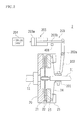
- FIG. 2 is a cross-sectional view of the configuration of the automatic clutch 2 according to an embodiment of the present invention.
- the automatic clutch 2 according to the present embodiments includes a dry single plate friction clutch 20 (hereafter simply referred to as "clutch 20") and a clutch operation device 200.
- the clutch 20 includes a flywheel 21, a clutch disc 22, a pressure plate 23, a diaphragm spring 24, and a clutch cover 25.
- the flywheel 21 is linked to the crankshaft 11.
- the clutch cover 25 is rotatably, integrally attached to the flywheel 21.
- the clutch disc 22 is disposed opposite to the flywheel 21 and splined to an input shaft 31 of the transmission 3 so as to be fixed.
- the pressure plate 23 is disposed between the clutch disc 22 and the clutch cover 25.
- the pressure plate 23 is pressed against the flywheel 21 side by the outer peripheral portion of the diaphragm spring 24.
- the pressing force applied on the pressure plate 23 causes a friction force between the clutch disc 22 and the pressure plate 23 and between the flywheel 21 and the clutch disc 22.
- the crankshaft 11 and the input shaft 31 of the transmission 3 rotate integrally so as to transmit a torque between the engine 1 and the transmission 3.
- the maximum torque that can be transmitted via the clutch 20 between the engine 1 and the transmission 3 is referred to as "clutch torque Tc" in the following description.
- the clutch torque Tc is set as a value larger than revolution torque (engine torque Te) of the crankshaft 11 in order to prevent the occurrence of the slippage in the clutch 20.
- the clutch operation device 200 includes a release bearing 201, a release fork 202, and a hydraulic clutch actuator 203 and moves the pressure plate 23 of the clutch 20 in an axial direction (right-and-left direction in FIG. 2 ) so as to set the clutch disc 22 in a state where the clutch disc 22 is held between the pressure plate 23 and the flywheel 21 or in a state where the clutch disc 22 is separated between the pressure plate 23 and the flywheel 21.
- the release bearing 201 is movably engaged with the input shaft 31 of the transmission 3 in the axial direction thereof (right-and-left direction in FIG. 2 ) and abutted on the center portion of the diaphragm spring 24.
- the release fork 202 is a member to transfer the release bearing 201 in the direction in which the release bearing 201 comes in contact with or detached from the flywheel 21 (right-and-left direction in FIG. 2 ).
- the clutch actuator 203 includes a cylinder including an oil chamber 203a and a piston rod 203b, and reciprocates the piston rod 203b (advances forward and backward) so as to rotate the release fork 202 about a fulcrum point 202a.
- the actuation of the clutch actuator 203 is controlled by a hydraulic control circuit 204 and the ECU 100. Specifically, when the clutch actuator 203 in the state (clutch-coupled state) shown in FIG. 2 is driven so as to move the piston rod 203b forward (move to the right in FIG. 2 ), then the release fork 202 is rotated about the fulcrum point 202a (rotated in the clockwise direction in FIG. 2 ), and in accordance with this rotation, the release bearing 201 is moved toward the flywheel 21 side (left side in FIG. 2 ).
- the central portion of the diaphragm spring 24 (that is, the portion of the diaphragm spring 24 that is abutted on the release bearing 201) is moved toward the flywheel 21 side (left side in FIG. 2 ), which causes the diaphragm spring 24 to be reversed. Accordingly, the pressing force of the pressure plate 23, which is applied by the diaphragm spring 24, becomes weak, so that the friction forces decrease between the clutch disc 22 and the pressure plate 23, and between the flywheel 21 and the clutch disc 22, which puts the clutch 20 in a decoupled (released) state.
- clutch stroke St the travel distance (hereinafter referred to as "clutch stroke St") of the piston rod 203b of the clutch actuator 203 is detected by a clutch stroke sensor 408.
- the output signal of the clutch stroke sensor 408 is inputted to the ECU 100 (see FIG. 5 ).
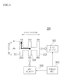
- FIG. 3 is a configuration diagram illustrating a gate mechanism and an actuator of a shift operation device according to an embodiment of the present invention.
- the transmission 3 has a configuration similar to that of a common manual transmission such as a parallel gear type transmission having five forward shift stages and one backward shift stage.
- the input shaft 31 of the transmission 3 is coupled to the clutch disc 22 of the clutch 20 (see FIG. 2 ).
- the transmission 3 includes an input side gear group 33 and an output side gear group 34.
- the input side gear group 33 is coupled to the input shaft 31, and the output side gear group 34 is coupled to an output shaft 32.
- any one of gears in the input side gear group 33 is engaged with any one of gears in the output side gear group 34, so as to select a gear stage in accordance with the engaged gears.
- the revolution torque of the output shaft 32 of the transmission 3 is transmitted to drive wheels 7 through a drive shaft 4, a differential gear 5, a shaft 6, and the like.
- the revolution of the input shaft 31 of the transmission 3 (the output side revolution of the clutch 20: hereinafter referred to as "clutch revolution Nc") is detected by an input shaft revolution sensor 403. Also, the revolution of the output shaft 32 of the transmission 3 is detected by an output shaft revolution sensor 404. Based on a ratio of the revolution (output revolution/input revolution) obtained from output signals of the input shaft revolution sensor 403 and the output shaft revolution sensor 404, a current gear stage of the transmission 3 is determined.
- the shift operation device 300 including a shift fork, a select-and-shift shaft, collectively constituting an automated manual transmission (AMT: Automatic Manual Transmission) in which a gear shift operation is automatically carried out.
- AMT Automatic Manual Transmission
- the shift operation device 300 includes a hydraulic select actuator 301 to carry out an operation in the select direction (select operation), a hydraulic shift actuator 302 to carry out an operation in the shift direction (shift operation), and a hydraulic circuit 303 to control the hydraulic pressure of hydraulic oil to be supplied to the actuators 301 and 302.
- a plurality of gates including shift positions to define a gear stage are arranged along the select direction. Specifically, for example, as shown in FIG. 3 , a first gate 311 to define a first speed (1st) and a second speed (2nd), a second gate 312 to define a third speed (3rd) and a fourth speed (4th), and a third gate 313 to define a fifth speed (5th) and a reverse (Rev) are arranged along the select direction.
- a solenoid valve to activate a valve body upon the energization of an excitation coil, and the like are provided.
- the excitation coil disposed in the solenoid valve is energized and unenergized, the supply of oil pressure or the release of the oil pressure provided for the select actuator 301 and the shift actuator 302 is controlled.
- a solenoid control signal (hydraulic designating value) from the ECU 100 is inputted to the hydraulic circuit 303 of the shift operation device 300.
- the hydraulic circuit 303 separately drivingly controls the select actuator 301 and the shift actuator 302 based on the solenoid control signal inputted from the ECU 100.
- the select operation and the shift operation of the transmission 3 are executed.
- the select operation amount and the shift operation amount are detected by a shift select stroke sensor 409 (see FIG. 5 ).
- FIG. 4 is a plan view of a shift gate 92 of the shift device 9 according to an embodiment of the present invention.
- the shift device 9 is disposed adjacent to a driver seat of the vehicle.
- a shift lever 91 is movably operably provided for the shift device 9.
- the shift gate 92 in the shift device 9 including a parking position (P), a reverse position (R), a neutral position (N), a drive position (D), and a sequential position (S), having a configuration which allows a driver to move the shift lever 91 to a shift position that the driver desires (see FIG. 1 ).
- Each shift position such as the parking position (P), the reverse position (R), the neutral position (N), the drive position (D), and the sequential position (S) (including "+" position and "-” position described later) is detected by a shift position sensor 406 (see FIG. 5 ).
- the shift lever 91 when the shift lever 91 is operated to "the sequential position (S)" of the shift gate 92, and the shift lever 91 is operated to "+" position and "-" position with respect to the position (S) of the shift gate 92 as a neutral position, the forward gear stages of the transmission 3 are upshifted or downshifted. Specifically, every time the shift lever 91 is operated to the "+" position of the shift gate 92, the gear stage is upshifted on a one-by-one basis (for example, 1st ⁇ 2nd ⁇ ... ⁇ 5th). On the other hand, every time the shift lever 91 is operated to the "-" position of the shift gate 92, the gear stage is downshifted on the one-by-one basis (for example, 5th ⁇ 4th ⁇ ... ⁇ 1st).
- FIG. 5 is a functional configuration diagram illustrating a functional configuration of the ECU 100 according to an embodiment of the present invention.
- the ECU 100 includes a CPU (Central Processing Unit), a ROM (Read Only Memory), a RAM (Random Access Memory), a backup RAM, and an EEPROM (Electrically Erasable Programmable Read-Only Memory) to control a throttle motor 121, a clutch operation device 200, the shift operation device 300, and the like.
- a CPU Central Processing Unit
- ROM Read Only Memory
- RAM Random Access Memory
- EEPROM Electrically Erasable Programmable Read-Only Memory
- the ROM stores various control programs, table data (or map data), and the like to be referred to when executing those various control programs.
- the CPU reads out and executes the various control programs stored in the ROM so as to carry out various processes.
- the RAM is a memory that temporarily stores results of arithmetic operations with the CPU and data inputted from each of the sensors, and the like.
- the backup RAM is a nonvolatile memory that stores data that need storing, and the like, for example, when the engine 1 is stopped.
- the EEPROM is a re-writable nonvolatile memory that stores information and the like, on coordinates of a position P in the stroke direction at a full engagement point on a torque characteristic curve described later.
- the ECU 100 is connected to the engine revolution sensor 401, the throttle opening degree sensor 402, the input shaft revolution sensor 403, the output shaft revolution sensor 404, an accelerator opening degree sensor 405 to detect the opening degree of the accelerator pedal 8, a shift position sensor 406 to detect the shift position of the shift device 9, a brake pedal sensor 407 to detect a depressing amount of the brake pedal, the clutch stroke sensor 408 to detect the clutch stroke St of the automatic clutch 2, the shift select stroke sensor 409, and the like, and the signals from each of these sensors are inputted to the ECU 100.
- the accelerator opening degree sensor 405 corresponds to part of an opening degree detection means described in Claims.
- the ECU 100 is connected to a throttle motor 13 that opens and closes the throttle valve 12, the clutch operation device 200 of the automatic clutch 2, the shift operation device 300 of the transmission 3, and the like as a control target.
- the ECU 100 executes various kinds of control of the engine 1, including the opening degree control of the throttle valve 12 of the engine 1 based on the output signals of the above-described various sensors. Also, the ECU 100 outputs a control signal to the clutch operation device 200 of the automatic clutch 2 at the time of shifting in the transmission 3, and the like so as to let the clutch 2 execute coupling and decoupling operations. Further, the ECU 100 outputs a control signal (oil pressure designating value) to the shift operation device 300 of the transmission 3 based on the output signals of the above-described various sensors so as to execute the shift control to change the gear stages of the transmission 3.
- a control signal oil pressure designating value
- the CPU reads out and executes control programs stored in the ROM so as to classifiably function as an opening degree detection unit 101, a revolution storing unit 102, a reference setting unit 103, a revolution detection unit 104, a correction amount storing unit 105, a correction amount calculation unit 106, a torque characteristic storing unit 107, a full engagement storing unit 108, a correction unit 109, a stroke instruction unit 110, an engagement determination unit 111, a learning determination unit 112, and a learning execution unit 113.
- the automatic clutch control apparatus includes the opening degree detection unit 101, the revolution storing unit 102, the reference setting unit 103, the revolution detection unit 104, the correction amount storing unit 105, the correction amount calculation unit 106, the torque characteristic storing unit 107, the full engagement storing unit 108, the correction unit 109, the stroke instruction unit 110, the engagement determination unit 111, the learning determination unit 112, and the learning execution unit 113.
- the opening degree detection unit 101 serves as a function unit to detect an accelerator opening degree ⁇ (%), which indicates the opening degree of the accelerator pedal 8, via the accelerator opening degree sensor 405.
- the opening degree detection unit 101 corresponds to part of an opening degree detection means described in Claims.
- the revolution storing unit 102 serves as a function unit to store in advance reference revolution NS1 that is engine revolution Ne that outputs the engine torque Te required for the vehicle to advance in accordance with the accelerator opening degree ⁇ .
- the revolution storing unit 102 corresponds to a revolution storing means described in Claims.
- the revolution storing unit 102 stores the engine revolution Ne that outputs the engine torque Te by which the vehicle is accelerated at a constant acceleration ⁇ ( ⁇ ) in accordance with the accelerator opening degree ⁇ , as the reference revolution NS1, in a period during which the automatic clutch 2 operates from an engagement start point to a full engagement point.
- the revolution storing unit 102 is realized as tables (or maps) stored in the ROM and the like in the ECU 100.
- the reference revolution NS1 is a target value of the engine revolution Ne to accelerate the vehicle at the constant acceleration ⁇ ( ⁇ ) in accordance with the accelerator opening degree ⁇ in the period during which the automatic clutch 2 operates from the engagement start point to the full engagement point. That is, the larger the accelerator opening degree ⁇ is, the larger the acceleration ⁇ ( ⁇ ) becomes. Also, the larger the acceleration ⁇ ( ⁇ ) is, the larger the clutch torque Tc and the engine torque Te become, which leads to a large value in terms of the reference revolution NS1. Accordingly, the larger the accelerator opening degree ⁇ is, the larger the reference revolution NS1 is set, as described later referring to FIG. 6 .
- the reference setting unit 103 serves as a function unit to set the reference revolution NS that is the engine revolution Ne that outputs the engine torque Te required for the vehicle to advance based on the accelerator opening degree ⁇ detected by the opening degree detection unit 101.
- the reference setting unit 103 corresponds to a reference setting means described in Claims.
- the reference setting unit 103 reads out the reference revolution NS1 in accordance with the accelerator opening degree ⁇ detected by the opening degree detection unit 101 from the revolution storing unit 102 and carries out "delay processing" in which a time delay is provided and “moderating processing” in which variation is moderated, for the reference revolution NS 1 to be read out, so as to set the reference revolution NS.
- delay processing is processing in which output is delayed only by a predetermined delay time TB (for example, 100 msec).
- moderating processing is such that the reference revolution NS is obtained from the reference revolution NS1 read out from the revolution storing unit 102 based on the following formula (1) so as to set the reference revolution NS.
- NS n ⁇ ⁇ NS ⁇ 1 n + 1 - ⁇ ⁇ NS ⁇ 1 ⁇ n - 1
- (n) means a value of the reference revolution obtained through this processing
- (n - 1) means a value of the reference revolution obtained through the previous processing.
- the constant ⁇ is a value that is larger than "0" and less than "1" (for example, 0.5). It is noted that the effect of moderating the variation in the reference revolution NS is remarkable in proportion to the small magnitude of the constant ⁇ . Also, it is preferable that the delay time TB and the constant ⁇ be appropriately set in accordance with variation delay of the engine revolution Ne with respect to variation in the accelerator opening degree ⁇ of the vehicle, and the like.
- the reference revolution NS is set in a manner that the reference revolution NS in accordance with the accelerator opening degree ⁇ to be detected is read out from the revolution storing unit 102, so that the appropriate reference revolution NS is set with a simple configuration.
- the reference setting unit 103 reads out the reference revolution NS1 in accordance with the accelerator opening degree ⁇ from the revolution storing unit 102 so as to set the reference revolution NS.
- a mode may be applied that the reference setting unit 103 sets the reference revolution NS based on the accelerator opening degree ⁇ by another method.
- a mode may be applied that the reference setting unit 103 obtains the reference revolution NS 1 according to a formula in which the reference revolution NS 1 is obtained from the accelerator opening degree ⁇ , so as to set the reference revolution NS.
- the reference setting unit 103 sets the reference revolution NS1 based on the accelerator opening degree ⁇ .
- a mode may be applied that the reference setting unit 103 sets the reference revolution NS1 based on at least any one of the throttle opening degree and the accelerator opening degree ⁇ .
- a mode may be applied that the reference setting unit 103 sets the reference revolution NS1 based on the throttle opening degree detected by the throttle opening degree sensor 402.
- the engine revolution Ne that outputs the engine torque Te to accelerate the vehicle at the constant acceleration ⁇ ( ⁇ ) in accordance with the accelerator opening degree ⁇ is set as the reference revolution NS1, so that the reference revolution NS is set to an appropriate value.
- the vehicle when the vehicle starts moving, and the vehicle is accelerated at the constant acceleration ⁇ ( ⁇ ) in accordance with the accelerator opening degree ⁇ in the period during which the automatic clutch 2 operates from the engagement start point to the full engagement point, the vehicle advances smoothly. Accordingly, the engine revolution Ne that outputs the engine torque Te to accelerate the vehicle at the constant acceleration ⁇ ( ⁇ ) in accordance with the accelerator opening degree ⁇ is set as the reference revolution NS1, so that the reference revolution NS is set to an appropriate value.
- the reference setting unit 103 sets the engine revolution Ne that outputs the engine torque Te to accelerate the vehicle at the predetermined constant acceleration ⁇ 0 set as the reference revolution NS in the period during which the automatic clutch 2 operates from the engagement start point to the full engagement point.
- a mode may be applied that the reference setting unit 103 sets the reference revolution NS 1 that is the engine revolution Ne that outputs the engine torque Te required for the vehicle to advance.
- a mode may be applied that the reference setting unit 103 sets the engine revolution Ne that outputs the engine torque Te to accelerate the vehicle at the acceleration that is gradually increased, as the reference revolution NS1, in the period during which the automatic clutch 2 operates from the engagement start point to the full engagement point. In this case when the automatic clutch 2 reaches the engagement start point, that is, the acceleration is low at the start of advancing, which allows the vehicle to advance more smoothly.
- the reference setting unit 103 carries out the delay processing and the moderating processing for the reference revolution NS1 read out from the revolution storing unit 102 to set the reference revolution NS, so that the more appropriate reference revolution NS is set.
- the reference setting unit 103 carries out the delay processing and the moderating processing for the reference revolution NS1 read out from the revolution storing unit 102 to set the reference revolution NS.
- a mode may be applied that the reference setting unit 103 carries out at least any one of the delay processing and the moderating processing for the reference revolution NS read out from the revolution storing unit 102 to set the reference revolution NS.
- the reference setting unit 103 carries out moving average processing as "moderating processing".
- a mode may be applied that the reference setting unit 103 carries out another type of processing (for example, low pass filter processing) as "moderating processing”.
- FIG. 6 is a graph illustrating a relationship between the accelerator opening degree ⁇ and the reference revolution NS 1 according to an embodiment of the present invention.
- the horizontal axis represents the accelerator opening degree ⁇ (%)
- the vertical axis represents the reference revolution NS 1.
- the reference revolution NS1 is set larger in proportion to the magnitude of the accelerator opening degree ⁇ . It is noted that when the accelerator opening degree ⁇ is "0 %", the reference revolution NS1 is idling revolution N0 of the engine 1.
- FIG. 6 is a graph illustrating a relationship between the accelerator opening degree ⁇ and the reference revolution NS 1 according to an embodiment of the present invention.
- the horizontal axis represents the accelerator opening degree ⁇ (%)
- the vertical axis represents the reference revolution NS 1.
- the reference revolution NS1 is set larger in proportion to the magnitude of the accelerator opening degree ⁇ . It is noted that when the accelerator opening degree ⁇ is "0 %", the reference revolution NS1 is idling revolution N0 of the engine 1.
- the relationship between the accelerator opening degree ⁇ and the reference revolution NS1 may be obtained in accordance with the characteristics of the engine 1, and the like based on a simulation, an experiment, and the like while referring to the acceleration ⁇ , the clutch torque Tc, and the engine torque Te.
- FIG. 7 is a graph illustrating a relationship between the engine revolution Ne and the engine torque Te according to an embodiment of the present invention.
- the horizontal axis represents the engine revolution Ne
- the vertical axis represents the engine torque Te.
- Graphs G21, G22, and G23 of FIG. 7 are graphs illustrating a relationship between the engine revolution Ne and the engine torque Te while the accelerator opening degree ⁇ is constant.
- the accelerator opening degrees ⁇ corresponding to the Graphs G21, G22, and G23 are described as accelerator opening degrees ⁇ 1, ⁇ 2, and ⁇ 3.
- accelerator opening degree ⁇ increases in the order of the accelerator opening degrees ⁇ 1, ⁇ 2, and ⁇ 3 (herein, ⁇ 1 ⁇ ⁇ 2 ⁇ ⁇ 3), as shown in the Graphs G21, G22, and G23, the graph showing the relationship between the engine revolution Ne and the engine torque Te parallelly moves in general in the direction shown in an arrow VE (upwardly to the right).
- the engine torque Te is the engine torque Te1.
- the engine torque Te is the engine torque Te2.
- the engine torque Te is the engine torque Te3.
- the engine torque Te is determined in accordance with the accelerator opening degree ⁇ and the engine revolution Ne.
- the revolution detection unit 104 serves as a function unit to detect the engine revolution Ne via the engine revolution sensor 401.
- the revolution detection unit 104 corresponds to part of a revolution detection means described in Claims.
- the correction amount storing unit 105 serves as a function unit to store in advance a relationship between a revolution difference ⁇ N that is the subtraction of the reference revolution NS from the engine revolution Ne detected by the revolution detection unit 104, and a correction amount ⁇ S of the clutch stroke St instructed to the automatic clutch 2.
- the correction amount storing unit 105 corresponds to part of a correction amount calculation means described in Claims.
- the correction amount storing unit 105 is realized as tables (or maps) stored in the ROM and the like in the ECU 100.
- FIG. 8 is a graph illustrating a relationship between the revolution difference ⁇ N and the correction amount ⁇ S that are stored in the correction amount storing unit 105 according to an embodiment of the present invention.
- the horizontal axis represents the revolution difference ⁇ N
- the vertical axis represents the correction amount ⁇ S.
- the relationship between the revolution difference ⁇ N and the correction amount ⁇ S may be obtained in accordance with the characteristics of the engine 1 and the like based on a simulation, an experiment, and the like.
- the correction amount calculation unit 106 serves as a function unit to obtain the correction amount ⁇ S of the clutch stroke St instructed to the automatic clutch 2 based on the revolution difference ⁇ N that is subtraction of the reference revolution NS from the engine revolution Ne detected by the revolution detection unit 104.
- the correction amount calculation unit 106 corresponds to part of a correction amount calculation means described in Claims.
- the correction amount calculation unit 106 reads out the correction amount ⁇ S of the clutch stroke St instructed to the automatic clutch 2 corresponding to the revolution difference ⁇ N that is the subtraction of the reference revolution NS from the engine revolution Ne detected by the revolution detection unit 104, from the correction amount storing unit 105 so as to set the correction amount ⁇ S.
- the torque characteristic storing unit 107 serves as a function unit to store in advance a torque characteristic curve (see FIGs. 9 and 10 ) showing a relationship between the clutch stroke St and the clutch torque Tc.
- the torque characteristic storing unit 107 is realized as tables (or maps) stored in the ROM and the like in the ECU 100.
- the full engagement storing unit 108 serves as a function unit to store information on coordinates of the position P in the stroke direction at the full engagement point on the torque characteristic curve (see FIGs. 9 and 10 ).
- the full engagement storing unit 108 corresponds to a full engagement storing means described in Claims.
- the full engagement storing unit 108 is realized by the EEPROM and the like in the ECU 100.
- the information on the coordinates of the position P in the stroke direction at the full engagement point on the torque characteristic curve stored in the full engagement storing unit 108 (see FIGs. 9 and 10 ) is re-written by the learning execution unit 113.
- the correction unit 109 serves as a function unit to correct the clutch stroke St instructed to the automatic clutch 2 by correcting the torque characteristic curve in such a manner that the engine revolution Ne detected by the revolution detection unit 104 (hereinafter referred to as "detection revolution Ne") is brought close to the reference revolution NS set by the reference setting unit 103.
- detection revolution Ne the engine revolution Ne detected by the revolution detection unit 104
- the correction unit 109 corresponds to a correction means described in Claims.
- the correction unit 109 corrects the clutch stroke St instructed to the automatic clutch 2 by correcting the position P at the full engagement point on the torque characteristic curve in the stroke direction. More specifically, when the detection revolution Ne is larger than the reference revolution NS (that is, when the revolution difference ⁇ N is positive), the correction unit 109 corrects the position P at the full engagement point on the torque characteristic curve to the side to which the automatic clutch 2 is coupled. When the detection revolution Ne is smaller than the reference revolution NS (that is, when the revolution difference ⁇ N is negative), the correction unit 109 corrects the position P at the full engagement point on the torque characteristic curve to the side from which the automatic clutch 2 is decoupled. Also, the correction unit 109 corrects the position P at the full engagement point on the torque characteristic curve only by the absolute value of the correction amount ⁇ S obtained by the correction amount calculation unit 106 in the stroke direction.
- FIGs. 9 and 10 are graphs illustrating correction of the torque characteristic curve.
- the horizontal axis represents the clutch stroke St
- the vertical axis represents the clutch torque Tc.
- FIG. 9 is one example where the revolution difference ⁇ N is positive
- FIG. 10 is one example where the revolution difference ⁇ N is negative.
- Graph G41 is a graph illustrating the torque characteristic curve before correction.
- Graph G42 is a graph illustrating the torque characteristic curve after correction.
- the correction unit 109 parallelly moves the torque characteristic curve shown in the Graph G41 only by the absolute value of the correction amount ⁇ S in the stroke direction. That is, the correction unit 109 corrects a position P1 at the full engagement point on the torque characteristic curve shown in the Graph G41 down to a position P2 at the full engagement point on the torque characteristic curve shown in the Graph G42.
- the clutch stroke St corresponding to the clutch torque Tc1 is corrected from the clutch stroke St1 to the clutch stroke St2, to the side to which the automatic clutch 2 is coupled.
- Graph G43 is a graph illustrating the torque characteristic curve before correction.
- Graph G44 is a graph illustrating the torque characteristic curve after correction.
- the correction unit 109 parallelly moves the torque characteristic curve shown in the Graph G43 only by the absolute value of the correction amount ⁇ S in the stroke direction. That is, the correction unit 109 corrects a position P3 at the full engagement point on the torque characteristic curve shown in the Graph G43 up to a position P4 at the full engagement point on the torque characteristic curve shown in the Graph G44.
- the clutch stroke St corresponding to the clutch torque Tc2 is corrected from the clutch stroke St3 to the clutch stroke St4, to the side from which the automatic clutch 2 is decoupled.
- the correction amount ⁇ S of the clutch stroke St instructed to the automatic clutch 2 is obtained by the correction amount calculation unit 106 based on the revolution difference ⁇ N that is the subtraction of the reference revolution NS from the detection revolution Ne, and the position P at the full engagement point on the torque characteristic curve is corrected by the correction unit 109 only by the absolute value of the correction amount ⁇ S to be obtained in the stroke direction (the right-and-left direction in FIGs. 9 and 10 ), so that the clutch stroke St is more appropriately corrected.
- the correction unit 109 may correct the position P at the full engagement point on the torque characteristic curve only by the correction amount ⁇ S obtained by the correction amount calculation unit 106 in the stroke direction (the right-and-left direction in FIG. 9 ).
- the stroke instruction unit 110 serves as a function unit to obtain the clutch stroke St based on the torque characteristic curve corrected by the correction unit 109 and instructs the clutch stroke St to the automatic clutch 2. Specifically, the stroke instruction unit 110 obtains the clutch stroke St in the following procedures and instructs the clutch stroke St to the automatic clutch 2. First, the stroke instruction unit 110 changes the clutch stroke St at a constant speed from a time when the accelerator pedal 8 is depressed to the engagement start point.
- the engine torque Te is assumed based on the engine revolution Ne detected by the revolution detection unit 104 in a period ranging from the arrival at the engagement start point to the arrival at the full engagement point. That is, the engine torque Te corresponding to the accelerator opening degree ⁇ and the engine revolution Ne is obtained, referring to the graphs shown in FIG. 7 . Then, the clutch stroke St is obtained based on the torque characteristic curve corrected by the correction unit 109 in such a manner that the engine torque Te to be obtained corresponds with the clutch torque Tc. In addition, after reaching the full engagement point, the clutch stroke St is changed up to the stroke end position at the constant speed.
- the engagement determination unit 111 serves as a function unit to determine whether the clutch stroke St reaches the full engagement point.
- the engagement determination unit 111 corresponds to an engagement determination means described in Claims. Specifically, when the output shaft revolution of the automatic clutch 2 (herein, input shaft revolution Ni detected by the input shaft revolution sensor 403) has approximately corresponded with the detection revolution Ne, the engagement determination unit 111 determines that the clutch stroke St has reached the full engagement point.
- “approximately corresponded with” means that the revolution difference that is the subtraction of the input shaft revolution Ni from the detection revolution Ne is equal to or less than 50 rpm.
- the learning determination unit 112 serves as a function unit to determine whether the detection revolution Ne corresponds with the reference revolution NS, and turn on a learning flag indicating that the position P at the full engagement point on the torque characteristic curve can be learned in the case when it is determined that the detection revolution Ne corresponds with the reference revolution NS.
- the learning determination unit 112 corresponds to a learning determination means described in Claims.
- the learning determination unit 112 determines that the detection revolution Ne corresponds with the reference revolution NS.
- FIG. 11 is a timing chart illustrating a timing when the learning flag is turned on according to an embodiment of the present invention.
- all the horizontal axes of the graphs represent a time t, and in the order beginning at the top, Graph G52 (dashed line) showing the variation in the reference revolution NS, Graph G51 (solid line) showing the variation in the engine revolution Ne, Graph G53 showing the variation in a timer value TM, and Graph G54 showing the timing of turning on the learning flag are shown.
- the timer value TM is a timer value to count an elapsed period of time with regard to a state where the absolute value of the revolution difference ⁇ N between the detection revolution Ne and the reference revolution NS is equal to or less than the predetermined threshold value ⁇ Nth.
- the description will be omitted regarding determination on whether a state where the variation amount per unit time of the detection revolution Ne is equal to or less than a predetermined threshold value ⁇ Neth continues for a predetermined second period or longer.
- the accelerator pedal 8 is depressed, and the accelerator opening degree ⁇ starts increasing, and accordingly, the reference revolution NS increases as shown in the Graph G52.
- the learning determination unit 112 starts determining whether the detection revolution Ne corresponds with the reference revolution NS at a time T12 when a predetermined period TA (for example, 500 msec) has passed from the time T11.
- TA for example, 500 msec
- the accelerator opening degree ⁇ stops increasing (the accelerator opening degree ⁇ becomes uniform), and accordingly, the reference revolution NS stops increasing as shown in the Graph G52 (the reference revolution NS becomes uniform).
- the absolute value of the revolution difference ⁇ N between the detection revolution Ne and the reference revolution NS is equal to or less than the predetermined threshold value ⁇ Nth, which starts counting up the timer value TM.
- FIG. 11 shows the revolution that is large by the threshold value ⁇ Nth and the revolution that is small by the threshold value ⁇ Nth in a thin solid line with the reference revolution NS as a reference.
- the timer value TM reaches the first period Tth as shown in the Graph G53, which turns on the learning flag as shown in the Graph G54.
- the learning determination unit 112 determines that the detection revolution Ne corresponds with the reference revolution NS when a state where the absolute value of the revolution difference ⁇ N between the detection revolution Ne and the reference revolution NS is equal to or less than the predetermined threshold value ⁇ Nth continues for the predetermined first period or longer, and a state where the variation amount ⁇ Ne per unit time ⁇ t of the detection revolution Ne is equal to or less than the predetermined threshold value ⁇ Neth continues for the predetermined second period or longer.
- a mode may be applied that the learning determination unit 112 determines that the detection revolution Ne corresponds with the reference revolution NS by another method.
- a mode may be applied that, when a state where the absolute value of the revolution difference ⁇ N between the detection revolution Ne and the reference revolution NS is equal to or less than the predetermined threshold value ⁇ Nth continues for the predetermined first period or longer, the learning determination unit 112 determines that the detection revolution Ne corresponds with the reference revolution NS. In this case, the processing is simplified.
- the learning execution unit 113 re-writes a position in the stroke direction at the full engagement point stored in the full engagement storing unit 108 as a position in the stroke direction at the full engagement point on the torque characteristic curve corrected by the correction unit 109 as a functional unit.
- the learning execution unit 113 corresponds to a learning execution means described in Claims.
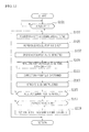
- FIG. 12 is a flowchart illustrating an operation of the ECU 100 according to an embodiment of the present invention.
- step S101 the determination on whether the vehicle starts advancing is carried out by the opening degree detection unit 101.
- step S101 is YES
- step S103 the processing proceeds to step S103.
- step S101 is NO, the processing is in a waiting state.
- the accelerator opening degree ⁇ is detected by the opening degree detection unit 101.
- a reference revolution NS that is the engine revolution Ne that outputs the engine torque Te required for the vehicle to advance based on the accelerator opening degree ⁇ detected at step S103 is set by the reference setting unit 103.
- the engine revolution Ne is detected by the revolution detection unit 104.
- step S109 the revolution difference ⁇ N that is the subtraction of the reference revolution NS set at step S105 from the detection revolution Ne detected at step S107 is obtained by the correction amount calculation unit 106.
- step S111 the correction amount ⁇ S of the clutch stroke St is obtained by the correction amount calculation unit 106 based on the revolution difference ⁇ N obtained at step S109.
- step S113 the position P at the full engagement point on the torque characteristic curve is corrected by the correction unit 109 in the stroke direction, and the clutch stroke St is obtained by the stroke instruction unit 110 based on the torque characteristic curve to be corrected and directed to the automatic clutch 2.
- step S 115 it is determined by the engagement determination unit 111 whether the clutch stroke St reaches the full engagement point.
- step S 115 is YES
- step S117 the processing is returned to step S 103, and the processing after step S103 is repeatedly executed.
- step S117 it is determined by the learning determination unit 112 whether the detection revolution Ne corresponds with the reference revolution NS (the learning flag is ON).
- step S117 is YES
- step S117 NO
- step S101 the processing to determine whether the learning flag is ON
- step S119 a position in the stroke direction at the full engagement point stored in the full engagement storing unit 108 is re-written by the learning execution unit 113 as a position in the stroke direction at the full engagement point on the torque characteristic curve corrected by the correction unit 109 (that is, the learning of the torque characteristic curve is executed). Then, the processing is returned to step S101.
- FIG. 13 is a flowchart illustrating an operation of the learning feasibility determination processing according to an embodiment of the present invention. It is noted that the processing below is parallelly executed with the processing of FIG. 12 . Also, for convenience sake, the case where the second period is set as the same period as the first period TMth will be described.
- step S201 the determination on whether the vehicle starts advancing is carried out by the opening degree detection unit 101.
- step S201 is YES
- the processing proceeds to step S203.
- step S201 is NO, the processing is in a waiting state.
- step S203 it is determined by the learning determination unit 112 whether the clutch stroke St reaches the engagement start point.
- the determination on whether the clutch stroke St reaches the engagement start point is carried out based on whether the revolution of the input shaft 31 of the transmission 3 (clutch revolution Nc) is equal to or more than a predetermined threshold value (for example, 10 rpm).
- a predetermined threshold value for example, 10 rpm.
- step S205 the determination on whether the predetermined period TA (for example, 500 msec) has passed from the time when the clutch stroke St reaches the engagement start point is carried out by the learning determination unit 112.
- step S205 the processing proceeds to step S207.
- step S207 the determination on whether the absolute value of the revolution difference ⁇ N obtained at step S109 in the flowchart shown in FIG. 12 is equal to or less than the threshold value ⁇ Nth is carried out by the learning determination unit 112.
- step S207 is YES
- step S211 the processing proceeds to step S209.
- step S209 the timer value TM is reset to "0", and the learning flag is initialized to "OFF" by means of the learning determination unit 112, and the processing is returned to step S207. Then, the processing after step S207 is repeatedly executed.
- step S211 the variation amount ⁇ Ne per unit time ⁇ t of the detection revolution Ne is obtained by the learning determination unit 112. Then, at step S213, the determination on whether the absolute value of the variation amount ⁇ Ne obtained at step S211 is equal to less than the threshold value ⁇ Neth is carried out by the learning determination unit 112.
- step S213 is YES
- step S213 is NO
- step S215 the timer value TM is counted up only by "1" by the learning determination unit 112. Then, at step S217, the determination on whether the timer value TM reaches the first period TMth is carried out by the learning determination unit 112. When step S217 is YES, the processing proceeds to step S219. When step S217 is NO, the processing is returned to step S207, and the processing after step S207 is repeatedly executed.
- step S219 the learning flag is set to "ON" by the learning determination unit 112. Then, at step S221, the determination on whether the clutch stroke St reaches the full engagement point is carried out by the engagement determination unit 111.
- step S221 is YES
- step S201 the processing is returned to step S201.
- step S221 is NO
- step S207 the processing after step S207 is repeatedly executed.
- FIG. 14 is a timing chart illustrating an operation of the ECU 100 according to an embodiment of the present invention.
- all the horizontal axes of the graphs represent a time t, and in the order beginning at the top, Graph G61 showing the variation in the accelerator opening degree ⁇ , Graph G62 (solid line) showing the variation in the engine revolution Ne, Graph G63 (dashed line) showing the variation in the reference revolution NS, Graph G64 (solid line) showing the variation in the clutch revolution Nc, Graph G65 showing the variation in the correction value ⁇ S, and Graph G66 showing the variation in the clutch stroke St are shown.
- the accelerator opening degree ⁇ starts increasing at a time T31 and is fixed to a uniform value at a time T33.
- the reference revolution NS1 in accordance with the accelerator opening degree ⁇ is read out from the revolution storing unit 102, and "delay processing" in which a time delay is provided and “moderating processing” in which variation is moderated are applied to the reference revolution NS 1 to be read out, so as to set the reference revolution NS.
- the reference revolution NS starts increasing at a time T32 and is fixed to a uniform value at a time T35.
- the clutch stroke St is generally varied at a uniform speed (herein, decreases) from a time T31 when the accelerator pedal 8 is depressed, and the accelerator opening degree ⁇ starts increasing to a time T34 that is the engagement start point. Then, as shown in the Graph G64, the clutch 2 starts engaging at the time T34 that is the engagement start point, and the clutch revolution Nc starts increasing. At a time T36, the clutch revolution Nc corresponds with the engine revolution Ne, which leads to a full engagement state regarding the clutch 2. When the learning flag is ON, the learning is executed.
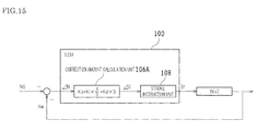
- FIG. 15 is a control block diagram illustrating a modification of a correction amount calculation unit according to an embodiment of the present invention.
- This embodiment is different from the embodiment shown in FIG. 5 because a correction amount calculation unit 106A is provided, instead of the correction amount calculation unit 106 in the functional configuration diagram shown in FIG. 5 .
- the correction amount calculation unit 106A is a PID control system in which the revolution difference ⁇ N that is the subtraction of the reference revolution NS from the engine revolution Ne is inputted, and the correction amount ⁇ S of the clutch stroke St is outputted, and its transfer function is defined by the following formula (2).
- each constant Kp, Ki, and Kd with regards to proportional term, integral term, and differential term are set in advance according to a hill climbing method and the like.
- the correction amount calculation unit 106A is provided as the PID control system. Accordingly, the appropriate setting of the constant Kp, Ki, and Kd provide the correction amount ⁇ S having a more appropriate value.
- control system constituting the correction amount calculation unit 106A is the PID control system including the proportional term, the integral term, and the differential term.
- a mode may be applied that the control system constituting the correction amount calculation unit 106A includes at least two terms out of the proportional term, the integral term, and the differential term.
- a mode may be applied that the control system constituting the correction amount calculation unit 106A is a PI control system including the proportional term and the integral term.
- the opening degree detection unit 101, the revolution storing unit 102, the reference setting unit 103, the revolution detection unit 104, the correction amount storing unit 105, the correction amount calculation unit 106 (or correction amount calculation unit 106A), the torque characteristic storing unit 107, the full engagement storing unit 108, the correction unit 109, the stroke instruction unit 110, the engagement determination unit 111, the learning determination unit 112, and the learning execution unit 113 are functionally constituted in the ECU 100.
- a mode may be applied that at least one unit, out of the opening degree detection unit 101, the revolution storing unit 102, the reference setting unit 103, the revolution detection unit 104, the correction amount storing unit 105, the correction amount calculation unit 106 (or correction amount calculation unit 106A), the torque characteristic storing unit 107, the full engagement storing unit 108, the correction unit 109, the stroke instruction unit 110, the engagement determination unit 111, the learning determination unit 112, and the learning execution unit 113, is realized by hardware such as an electronic circuit.
- the clutch 20 of the automatic clutch 2 is a dry single plate friction clutch.
- a mode may be applied that the clutch of the automatic clutch 2 is a friction clutch of another type.
- a mode may be applied that the clutch of the automatic clutch 2 is a dry DCT (Dual Clutch Transmission).
- the drive source of the automatic clutch 2 is hydraulic.
- a mode may be applied that the drive source of the automatic clutch 2 is a drive source of another type (for example, electric-powered).
- the present invention is applied to an automatic clutch control apparatus for an automatic clutch that is configured to alternate between a coupling state and a decoupling state by changing a clutch stroke and transmit a torque between an engine and a transmission in the coupling state, so as to correct a torque characteristic curve showing a relation between the clutch stroke and the clutch torque when a vehicle advances.
Landscapes
- Engineering & Computer Science (AREA)
- General Engineering & Computer Science (AREA)
- Physics & Mathematics (AREA)
- Fluid Mechanics (AREA)
- Mechanical Engineering (AREA)
- Hydraulic Clutches, Magnetic Clutches, Fluid Clutches, And Fluid Joints (AREA)
Abstract
Description
- The present invention relates to an automatic clutch control apparatus for an automatic clutch that is configured to alternate between a coupling state and a decoupling state by changing a clutch stroke and transmit a torque between an engine and a transmission in the coupling state, so as to correct a torque characteristic curve showing a relation between the clutch stroke and the clutch torque when a vehicle advances.
- Conventionally, there has been known a vehicle equipped with an automatic clutch that is interposed between an engine and a transmission and alternates between a coupling state and a decoupling state by changing a clutch stroke so as to alternate between transmission and disconnection of a torque between the engine and the transmission. Also, with respect to the vehicle equipped with the automatic clutch, there have been proposed various control apparatuses, control methods, and the like in which a torque characteristic curve showing a relation between a clutch stroke and a clutch torque is corrected or learned, in order to realize an operation of the vehicle that a driver desires.
- For example, there has been disclosed a clutch control apparatus in which the temperature of a clutch disc is assumed, and the clutch stroke is corrected based on the assumed temperature (see Patent Document 1). According to the clutch control apparatus described in
Patent Document 1, the clutch torque desirably is controlled corresponding to thermal expansion of constitutional components of the clutch. - Patent Document 1: Japanese Unexamined Patent Application Publication No.
2008-185217 - However, with respect to the clutch control apparatus described in
Patent Document 1, there has been the case where, when the assumed temperature of the clutch disc does not correspond with the actual temperature of the clutch disc, the desired clutch torque cannot be obtained. - For example, when the assumed temperature of the clutch disc is higher than the actual temperature of the clutch disc, the thermal expansion amount of the clutch disc is assumed larger than the actual thermal expansion amount of the clutch disc, which causes the actual clutch torque having a value lower than the desired clutch torque.
- The present invention has been achieved in view of the above circumstances to solve the technical problems, and it is an object of the present invention to provide an automatic clutch control apparatus that appropriately corrects a torque characteristic curve. Means of Solving the Problems
- In order to solve the problems described above, an automatic clutch control apparatus according to the present invention is configured as follows.
- That is, according to one aspect of the present invention, an automatic clutch control apparatus may be such that an automatic clutch is configured to alternate between a coupling state and a decoupling state by changing a clutch stroke and transmit a torque between an engine and a transmission in the coupling state, so as to correct a torque characteristic curve showing a relation between the clutch stroke and the clutch torque when a vehicle advances, and the automatic clutch control apparatus includes an opening degree detection means for detecting at least one out of a throttle opening degree and an accelerator opening degree, a reference setting means for setting a reference revolution that is an engine revolution that outputs an engine torque required for the vehicle to advance, based on at least one out of the throttle opening degree and the accelerator opening degree detected by the opening degree detection means, a revolution detection means for detecting an engine revolution, and a correction means for correcting the clutch stroke instructed to the automatic clutch by correcting the torque characteristic curve in such a manner that the detection revolution that is the engine revolution detected by the revolution detection means is brought close to the reference revolution set by the reference setting means.
- According to the automatic clutch control apparatus of the above-described configuration, at least one out of the throttle opening degree and the accelerator opening degree is detected, and the reference revolution that is the engine revolution that outputs the engine torque required for the vehicle to advance is set based on at least one out of the throttle opening degree and the accelerator opening degree to be detected. Then, the engine revolution is detected, and the clutch stroke instructed to the automatic clutch is corrected by correcting the torque characteristic curve in such a manner that the detection revolution that is the engine revolution to be detected is brought close to the reference revolution to be set, so that the torque characteristic curve is appropriately corrected.
- That is, the setting of the reference revolution having an appropriate value leads to the setting of the engine revolution that outputs the engine torque required for the vehicle to advance as the reference revolution. In this case, the torque characteristic curve is corrected in such a manner that the detection revolution that is the engine revolution to be detected is brought close to the reference revolution to be set, and the torque characteristic curve is corrected to output the engine torque required for the vehicle to advance, so that the torque characteristic curve is appropriately corrected.
- According to another aspect of the present invention, it is preferable that the automatic clutch control apparatus be such that the reference setting means sets the engine revolution that outputs the engine torque to accelerate the vehicle at a uniform acceleration corresponding to at least one out of the throttle opening degree and the accelerator opening degree detected by the opening degree detection means as the reference revolution in a period during which the automatic clutch operates from an engagement start point to a full engagement point.
- According to the automatic clutch control apparatus of the above-described configuration, the engine revolution that outputs engine torque to accelerate the vehicle at the uniform acceleration corresponding to at least one out of the throttle opening degree and the accelerator opening degree to be detected is set as the reference revolution in the period during which the automatic clutch operates from the engagement start point to the full engagement point, so that the engine revolution having a more appropriate value is provided.
- That is, when the vehicle advances, and the vehicle is accelerated at the uniform acceleration corresponding to at least one out of the throttle opening degree and the accelerator opening degree in the period during which the automatic clutch operates from the engagement start point to the full engagement point, the vehicle advances smoothly. Accordingly, thus, the engine revolution that outputs the engine torque to accelerate the vehicle at the uniform acceleration corresponding to at least one out of the throttle opening degree and the accelerator opening degree is set as the reference revolution, so that the engine revolution having a more appropriate value is set.
- According to another aspect of the present invention, it is preferable that the automatic clutch control apparatus further include a revolution storing means for storing in advance the reference revolution corresponding to at least one out of the throttle opening degree and the accelerator opening degree, the revolution setting means sets the reference revolution by reading out, from the revolution storing means, the reference revolution corresponding to at least one out of the throttle opening degree and the accelerator opening degree detected by the opening degree detection means.
- According to the automatic clutch control apparatus of the above-described configuration, the reference revolution is stored in the revolution storing means in advance, corresponding to at least one out of the throttle opening degree and the accelerator opening degree, and the reference revolution is set by reading out, from the revolution storing means, the reference revolution corresponding to at least one out of the throttle opening degree and the accelerator opening degree to be detected, so that appropriate reference revolution is set with a simple configuration.
- According to another aspect of the present invention, it is preferable that the automatic clutch control apparatus be such that the revolution setting means carries out at least one out of "delay processing" and "moderating processing" with respect to the reference revolution read out from the revolution storing means so as to set the reference revolution.
- According to the automatic clutch control apparatus of the above-described configuration, at least one out of the "delay processing" and the "moderating processing" is carried out with respect to the reference revolution read out from the revolution storing means so as to set the reference revolution, so that the more appropriate reference revolution is set.
- According to another aspect of the present invention, it is preferable that the automatic clutch control apparatus be such that the correction means corrects a position at the full engagement point on the torque characteristic curve in the stroke direction so as to correct the clutch stroke instructed to the automatic clutch.
- According to the automatic clutch control apparatus of the above-described configuration, the position at the full engagement point on the torque characteristic curve is corrected in the stroke direction, which leads to the correction of the clutch stroke instructed to the automatic clutch, so that the clutch stroke is corrected with a simple configuration.
- According to another aspect of the present invention, it is preferable that the automatic clutch control apparatus be such that, when the detection revolution is larger than the reference revolution, the correction means corrects the position at the full engagement point on the torque characteristic curve to a side to which the automatic clutch is coupled, and when the detection revolution is smaller than the reference revolution, the correction means corrects the position at the full engagement point on the torque characteristic curve to a side from which the automatic clutch is decoupled.
- According to the automatic clutch control apparatus of the above-described configuration, when the detection revolution is larger than the reference revolution, the position at the full engagement point on the torque characteristic curve is corrected to the side to which the automatic clutch is coupled, and the detection revolution decreases so as to come close to the reference revolution, so that the clutch stroke is appropriately corrected. In contrast, when the detection revolution is smaller than the reference revolution, the position at the full engagement point on the torque characteristic curve is corrected to the side from which the automatic clutch is decoupled, and the detection revolution increases so as to come close to the reference revolution, so that the clutch stroke is appropriately corrected.
- According to another aspect of the present invention, it is preferable that the automatic clutch control apparatus further include a correction amount calculation means for obtaining a correction amount of the clutch stroke instructed to the automatic clutch based on a difference that is subtraction of the reference revolution from the detection revolution, the correction means corrects the position at the full engagement point on the torque characteristic curve in the stroke direction only by the correction amount obtained by the correction amount calculation means.
- According to the automatic clutch control apparatus of the above-described configuration, the correction amount of the clutch stroke instructed to the automatic clutch is obtained based on the difference that is the subtraction of the reference revolution from the detection revolution, and the position at the full engagement point on the torque characteristic curve is corrected in the stroke direction only by the correction amount to be obtained, so that the clutch stroke is more appropriately corrected. For example, as the magnitude of the absolute value of the difference that is the subtraction of the reference revolution from the detection revolution becomes larger, the magnitude of the absolute value the correction amount of the clutch stroke instructed to the automatic clutch is set larger, which provides the correction amount having an appropriate value.
- According to another aspect of the present invention, it is preferable that the automatic clutch control apparatus further include a full engagement storing means for storing the position in the stroke direction at the full engagement point on the torque characteristic curve, an engagement determination means for determining whether the clutch stroke reaches the full engagement point, a learning determination means for determining whether the detection revolution corresponds with the reference revolution, and a learning execution means for re-writing the position in the stroke direction at the full engagement point stored in the full engagement storing means as the position in the stroke direction at the full engagement point on the torque characteristic curve corrected by the correction means when the engagement determination means determines that the clutch stroke has reached the full engagement point, and only when the learning determination means determines that the detection revolution corresponds with the reference revolution.
- According to the automatic clutch control apparatus of the above-described configuration, the position in the stroke direction at the full engagement point on the torque characteristic curve is stored in the full engagement storing means, it is determined whether the clutch stroke reaches the full engagement point. Also, it is determined whether the detection revolution corresponds with the reference revolution. Then, when it is determined that the clutch stroke has reached the full engagement point, and only when it is determined that the detection revolution corresponds with the reference revolution, the position in the stroke direction at the full engagement point stored in the full engagement storing means is re-written as the position in the stroke direction at the full engagement point on the torque characteristic curve corrected by the correction means, so that the position in the stroke direction at the full engagement point on the torque characteristic curve is appropriately learned.
- That is, when the clutch stroke reaches the full engagement point, the clutch is in a coupled state, and the engine revolution corresponds with an input shaft revolution of the transmission. Accordingly, when the clutch stroke has reached the full engagement point, and the detection revolution corresponds with the reference revolution, it is assumed that the clutch stroke has appropriately been corrected. By learning the position in the stroke direction at the full engagement point on the torque characteristic curve corrected (herein, by re-writing the position in the stroke direction at the full engagement point stored in the full engagement storing means), the position in the stroke direction at the full engagement point on the torque characteristic curve is appropriately learned.
- According to another aspect of the present invention, it is preferable that the automatic clutch control apparatus be such that, when an output shaft revolution of the automatic clutch approximately corresponds with the detection revolution, the engagement determination means determines that the clutch stroke has reached the full engagement point.
- According to the automatic clutch control apparatus of the above-described configuration, when the output shaft revolution of the automatic clutch approximately corresponds with the detection revolution, it is determined that the clutch stroke has reached the full engagement point. Accordingly, it is determined that the clutch stroke has reached the full engagement point, with a simple configuration.
- According to another aspect of the present invention, it is preferable that the automatic clutch control apparatus be such that, when a state where an absolute value of a difference between the detection revolution and the reference revolution is equal to or less than a predetermined threshold value continues for a predetermined first period or longer, the learning determination means determines that the detection revolution corresponds with the reference revolution.
- According to the automatic clutch control apparatus of the above-described configuration, when the state where the absolute value of the difference between the detection revolution and the reference revolution is equal to or less than the predetermined threshold value continues for the predetermined first period or longer, it is determined that the detection revolution corresponds with the reference revolution. Accordingly, it is appropriately determined that the detection revolution corresponds with the reference revolution.
- According to another aspect of the present invention, it is preferable that the automatic clutch control apparatus be such that, only when a state where a variation amount per unit time of the detection revolution is equal to or less than a predetermined threshold value continues for a predetermined second period or longer, the learning determination means determines that the detection revolution corresponds with the reference revolution.
- According to the automatic clutch control apparatus of the above-described configuration, only when a state where the variation amount per unit time of the detection revolution is equal to or less than the predetermined threshold value continues for the predetermined second period or longer, it is determined that the detection revolution corresponds with the reference revolution. Accordingly, it is more appropriately determined that the detection revolution corresponds with the reference revolution.
- According to the automatic clutch control apparatus of the present invention, at least one out of the throttle opening degree and the accelerator opening degree is detected, and the reference revolution that is the engine revolution that outputs the engine torque required for the vehicle to advance is set based on at least one out of the throttle opening degree and the accelerator opening degree to be detected. Then, the engine revolution is detected, and the clutch stroke instructed to the automatic clutch is corrected by correcting the torque characteristic curve in such a manner that the detection revolution that is the engine revolution to be detected is brought close to the reference revolution to be set, so that the torque characteristic curve is appropriately corrected.
-
- [
FIG. 1] FIG. 1 is a configuration diagram illustrating an example of a power train and a control system for the same of a vehicle to which the present invention is applied. - [
FIG. 2] FIG. 2 is a cross-sectional view of a configuration of an automatic clutch according to an embodiment of the present invention. - [
FIG. 3] FIG. 3 is a configuration diagram illustrating a gate mechanism and an actuator of a shift operation device according to an embodiment of the present invention. - [
FIG. 4] FIG. 4 is a plane view of a shift gate of a shift device according to an embodiment of the present invention. - [
FIG. 5] FIG. 5 is a functional configuration diagram illustrating a functional configuration of an ECU according to an embodiment of the present invention. - [
FIG. 6] FIG. 6 is a graph illustrating a relationship between an accelerator opening degree and a reference revolution according to an embodiment of the present invention. - [
FIG. 7] FIG. 7 is a graph illustrating a relationship between an engine revolution and an engine torque according to an embodiment of the present invention. - [
FIG. 8] FIG. 8 is a graph illustrating a relationship between a correction amount of clutch stroke and a revolution difference that is the subtraction of the reference revolution from the detection revolution according to an embodiment of the present invention. - [
FIG. 9] FIG. 9 is a graph illustrating correction of a torque characteristic curve in a case when the detection revolution is larger than the reference revolution according to an embodiment of the present invention. - [
FIG. 10] FIG. 10 is a graph illustrating correction of the torque characteristic curve in a case when the detection revolution is smaller than the reference revolution according to an embodiment of the present invention. - [
FIG. 11] FIG. 11 is a timing chart illustrating a timing when a learning flag is turned on according to an embodiment of the present invention. - [
FIG. 12] FIG. 12 is a flowchart illustrating an operation of the ECU according to an embodiment of the present invention. - [
FIG. 13] FIG. 13 is a flowchart illustrating an operation of a learning feasibility determination processing according to an embodiment of the present invention. - [
FIG. 14] FIG. 14 is a timing chart illustrating an operation of the ECU according to an embodiment of the present invention. - [
FIG. 15] FIG. 15 is a control block diagram illustrating a modification of a correction amount calculation unit according to an embodiment of the present invention. - Hereinafter, embodiments of the present invention will be described referring to the drawings.
- First, a power train of a vehicle according to the embodiments of the present invention will be described referring to
FIG. 1. FIG. 1 is a configuration diagram illustrating an example of the power train and a control system for the same of the vehicle to which the present invention is applied. The control of the power train is executed by an ECU (Electronic Control Unit) 100 shown inFIG. 1 . Specifically, theECU 100 is constituted of, for example, an engine ECU, a transmission ECU, and an automatic clutch ECU, and these ECUs are connected so as to communicate with each other. - Also, as shown in
FIG. 1 , the power train of the vehicle according to the present embodiments includes anengine 1, anautomatic clutch 2, atransmission 3, and theECU 100. Hereinafter, theengine 1, theautomatic clutch 2, atransmission 3, and theECU 100 will be successively described. - The
engine 1 is an internal combustion engine such as a gasoline engine and a diesel engine. Acrankshaft 11 serving as an output shaft of theengine 1 is linked to aflywheel 21 of the automatic clutch 2 (seeFIG. 2 ). Also, the revolution of the crankshaft 11 (engine revolution Ne) is detected by anengine revolution sensor 401. Incidentally, theengine revolution sensor 401 corresponds to part of a revolution detection means described in Claims. - An air amount that is taken into the
engine 1 is controlled by athrottle valve 12. The opening degrees of the throttle valve 12 (throttle opening degrees) are configured to be controlled by means of theECU 100 without correlating with an accelerator pedal operation of a driver, and the throttle opening degrees are detected by a throttleopening degree sensor 402. - The throttle opening degrees of the
throttle valve 12 is controlled by theECU 100. Specifically, theECU 100 controls the throttle opening degrees of thethrottle valve 12 in order to introduce an appropriate intake air amount (target intake amount) in accordance with the operating states of theengine 1 such as the engine revolution Ne detected by theengine revolution sensor 401 and the amount of depressing of accelerator pedal (accelerator opening degrees) by a driver. - The configuration of the
automatic clutch 2 will be described referring toFIG. 2. FIG. 2 is a cross-sectional view of the configuration of theautomatic clutch 2 according to an embodiment of the present invention. Theautomatic clutch 2 according to the present embodiments includes a dry single plate friction clutch 20 (hereafter simply referred to as "clutch 20") and aclutch operation device 200. - The clutch 20 includes a
flywheel 21, aclutch disc 22, apressure plate 23, adiaphragm spring 24, and aclutch cover 25. Theflywheel 21 is linked to thecrankshaft 11. Also, theclutch cover 25 is rotatably, integrally attached to theflywheel 21. Theclutch disc 22 is disposed opposite to theflywheel 21 and splined to aninput shaft 31 of thetransmission 3 so as to be fixed. - The
pressure plate 23 is disposed between theclutch disc 22 and theclutch cover 25. Thepressure plate 23 is pressed against theflywheel 21 side by the outer peripheral portion of thediaphragm spring 24. The pressing force applied on thepressure plate 23 causes a friction force between theclutch disc 22 and thepressure plate 23 and between theflywheel 21 and theclutch disc 22. These friction forces put the clutch 20 into a coupled (engaged) state, so that theflywheel 21, theclutch disc 22, and thepressure plate 23 rotate integrally. - Thus, when the clutch 20 is in the coupled state, the
crankshaft 11 and theinput shaft 31 of thetransmission 3 rotate integrally so as to transmit a torque between theengine 1 and thetransmission 3. The maximum torque that can be transmitted via the clutch 20 between theengine 1 and thetransmission 3 is referred to as "clutch torque Tc" in the following description. When the clutch 20 is fully coupled (engaged), and theengine 1 is in a drive state, the clutch torque Tc is set as a value larger than revolution torque (engine torque Te) of thecrankshaft 11 in order to prevent the occurrence of the slippage in the clutch 20. - The
clutch operation device 200 includes a release bearing 201, arelease fork 202, and a hydraulicclutch actuator 203 and moves thepressure plate 23 of the clutch 20 in an axial direction (right-and-left direction inFIG. 2 ) so as to set theclutch disc 22 in a state where theclutch disc 22 is held between thepressure plate 23 and theflywheel 21 or in a state where theclutch disc 22 is separated between thepressure plate 23 and theflywheel 21. - The release bearing 201 is movably engaged with the
input shaft 31 of thetransmission 3 in the axial direction thereof (right-and-left direction inFIG. 2 ) and abutted on the center portion of thediaphragm spring 24. Therelease fork 202 is a member to transfer the release bearing 201 in the direction in which the release bearing 201 comes in contact with or detached from the flywheel 21 (right-and-left direction inFIG. 2 ). Theclutch actuator 203 includes a cylinder including anoil chamber 203a and apiston rod 203b, and reciprocates thepiston rod 203b (advances forward and backward) so as to rotate therelease fork 202 about afulcrum point 202a. - The actuation of the
clutch actuator 203 is controlled by ahydraulic control circuit 204 and theECU 100. Specifically, when theclutch actuator 203 in the state (clutch-coupled state) shown inFIG. 2 is driven so as to move thepiston rod 203b forward (move to the right inFIG. 2 ), then therelease fork 202 is rotated about thefulcrum point 202a (rotated in the clockwise direction inFIG. 2 ), and in accordance with this rotation, the release bearing 201 is moved toward theflywheel 21 side (left side inFIG. 2 ). Thus, with the movement of the release bearing 201, the central portion of the diaphragm spring 24 (that is, the portion of thediaphragm spring 24 that is abutted on the release bearing 201) is moved toward theflywheel 21 side (left side inFIG. 2 ), which causes thediaphragm spring 24 to be reversed. Accordingly, the pressing force of thepressure plate 23, which is applied by thediaphragm spring 24, becomes weak, so that the friction forces decrease between theclutch disc 22 and thepressure plate 23, and between theflywheel 21 and theclutch disc 22, which puts the clutch 20 in a decoupled (released) state. - Conversely, in the clutch-decoupled state, when the
piston rod 203b of theclutch actuator 203 is moved backward (moved to the left inFIG. 2 ), thepressure plate 23 is pressed toward theflywheel 21 side (left side inFIG. 2 ) by the elastic force of thediaphragm spring 24. The pressing force of thediaphragm spring 24, which is applied to thepressure plate 23, causes an increase in friction force between theclutch disc 22 and thepressure plate 23, and between theflywheel 21 and theclutch disc 22, and these friction forces put the clutch 20 in a coupled (engaged) state. - Also, the travel distance (hereinafter referred to as "clutch stroke St") of the
piston rod 203b of theclutch actuator 203 is detected by aclutch stroke sensor 408. The output signal of theclutch stroke sensor 408 is inputted to the ECU 100 (seeFIG. 5 ). - Next, the
transmission 3 will be described referring toFIGs. 1 to 3 .FIG. 3 is a configuration diagram illustrating a gate mechanism and an actuator of a shift operation device according to an embodiment of the present invention. For example, thetransmission 3 has a configuration similar to that of a common manual transmission such as a parallel gear type transmission having five forward shift stages and one backward shift stage. Theinput shaft 31 of thetransmission 3 is coupled to theclutch disc 22 of the clutch 20 (seeFIG. 2 ). - Also, as shown in
FIG. 1 , thetransmission 3 includes an inputside gear group 33 and an outputside gear group 34. The inputside gear group 33 is coupled to theinput shaft 31, and the outputside gear group 34 is coupled to anoutput shaft 32. Also, according to ashift operation device 300 described later, any one of gears in the inputside gear group 33 is engaged with any one of gears in the outputside gear group 34, so as to select a gear stage in accordance with the engaged gears. Further, the revolution torque of theoutput shaft 32 of thetransmission 3 is transmitted to drivewheels 7 through adrive shaft 4, a differential gear 5, a shaft 6, and the like. - The revolution of the
input shaft 31 of the transmission 3 (the output side revolution of the clutch 20: hereinafter referred to as "clutch revolution Nc") is detected by an inputshaft revolution sensor 403. Also, the revolution of theoutput shaft 32 of thetransmission 3 is detected by an outputshaft revolution sensor 404. Based on a ratio of the revolution (output revolution/input revolution) obtained from output signals of the inputshaft revolution sensor 403 and the outputshaft revolution sensor 404, a current gear stage of thetransmission 3 is determined. - In the
transmission 3 according to the present embodiments, there is provided theshift operation device 300 including a shift fork, a select-and-shift shaft, collectively constituting an automated manual transmission (AMT: Automatic Manual Transmission) in which a gear shift operation is automatically carried out. - As shown in
FIG. 3 , theshift operation device 300 includes a hydraulicselect actuator 301 to carry out an operation in the select direction (select operation), ahydraulic shift actuator 302 to carry out an operation in the shift direction (shift operation), and ahydraulic circuit 303 to control the hydraulic pressure of hydraulic oil to be supplied to theactuators - In the
shift operation device 300, a plurality of gates including shift positions to define a gear stage are arranged along the select direction. Specifically, for example, as shown inFIG. 3 , afirst gate 311 to define a first speed (1st) and a second speed (2nd), asecond gate 312 to define a third speed (3rd) and a fourth speed (4th), and athird gate 313 to define a fifth speed (5th) and a reverse (Rev) are arranged along the select direction. - When any one of the gates (for example, the first gate 311), out of the
first gate 311 to thethird gate 313, is selected according to the drive of theselect actuator 301, and theshift actuator 302 is driven, the switching of gear stages is carried out (for example, from neutral position (N) to the first speed (1st)). - In the
hydraulic circuit 303, a solenoid valve to activate a valve body upon the energization of an excitation coil, and the like are provided. When the excitation coil disposed in the solenoid valve is energized and unenergized, the supply of oil pressure or the release of the oil pressure provided for theselect actuator 301 and theshift actuator 302 is controlled. - Also, a solenoid control signal (hydraulic designating value) from the
ECU 100 is inputted to thehydraulic circuit 303 of theshift operation device 300. Thehydraulic circuit 303 separately drivingly controls theselect actuator 301 and theshift actuator 302 based on the solenoid control signal inputted from theECU 100. As a result, the select operation and the shift operation of thetransmission 3 are executed. Also, the select operation amount and the shift operation amount are detected by a shift select stroke sensor 409 (seeFIG. 5 ). - Next, a
shift device 9 will be described referring toFIGs. 1 and4. FIG. 4 is a plan view of ashift gate 92 of theshift device 9 according to an embodiment of the present invention. On the other hand, as shown inFIG. 1 , theshift device 9 is disposed adjacent to a driver seat of the vehicle. Ashift lever 91 is movably operably provided for theshift device 9. - Also, as shown in
FIG. 4 , there is formed theshift gate 92 in theshift device 9 including a parking position (P), a reverse position (R), a neutral position (N), a drive position (D), and a sequential position (S), having a configuration which allows a driver to move theshift lever 91 to a shift position that the driver desires (seeFIG. 1 ). Each shift position such as the parking position (P), the reverse position (R), the neutral position (N), the drive position (D), and the sequential position (S) (including "+" position and "-" position described later) is detected by a shift position sensor 406 (seeFIG. 5 ). - For example, when the
shift lever 91 is operated to "the drive position (D)" of theshift gate 92, a plurality of forward gear stages (forward five speeds) of thetransmission 3 are automatically shift-controlled in accordance with driving states of the vehicle. That is, the shift operation is carried out in an automatic mode. - In contrast, when the
shift lever 91 is operated to "the sequential position (S)" of theshift gate 92, and theshift lever 91 is operated to "+" position and "-" position with respect to the position (S) of theshift gate 92 as a neutral position, the forward gear stages of thetransmission 3 are upshifted or downshifted. Specifically, every time theshift lever 91 is operated to the "+" position of theshift gate 92, the gear stage is upshifted on a one-by-one basis (for example, 1st → 2nd → ... → 5th). On the other hand, every time theshift lever 91 is operated to the "-" position of theshift gate 92, the gear stage is downshifted on the one-by-one basis (for example, 5th → 4th → ... → 1st). - Next, the configuration of the
ECU 100 will be described referring toFIGs. 1 and5. FIG. 5 is a functional configuration diagram illustrating a functional configuration of theECU 100 according to an embodiment of the present invention. TheECU 100 includes a CPU (Central Processing Unit), a ROM (Read Only Memory), a RAM (Random Access Memory), a backup RAM, and an EEPROM (Electrically Erasable Programmable Read-Only Memory) to control athrottle motor 121, aclutch operation device 200, theshift operation device 300, and the like. - The ROM stores various control programs, table data (or map data), and the like to be referred to when executing those various control programs. The CPU reads out and executes the various control programs stored in the ROM so as to carry out various processes. The RAM is a memory that temporarily stores results of arithmetic operations with the CPU and data inputted from each of the sensors, and the like. The backup RAM is a nonvolatile memory that stores data that need storing, and the like, for example, when the
engine 1 is stopped. The EEPROM is a re-writable nonvolatile memory that stores information and the like, on coordinates of a position P in the stroke direction at a full engagement point on a torque characteristic curve described later. - The
ECU 100 is connected to theengine revolution sensor 401, the throttleopening degree sensor 402, the inputshaft revolution sensor 403, the outputshaft revolution sensor 404, an acceleratoropening degree sensor 405 to detect the opening degree of the accelerator pedal 8, ashift position sensor 406 to detect the shift position of theshift device 9, abrake pedal sensor 407 to detect a depressing amount of the brake pedal, theclutch stroke sensor 408 to detect the clutch stroke St of theautomatic clutch 2, the shiftselect stroke sensor 409, and the like, and the signals from each of these sensors are inputted to theECU 100. Incidentally, the acceleratoropening degree sensor 405 corresponds to part of an opening degree detection means described in Claims. - Also, the
ECU 100 is connected to athrottle motor 13 that opens and closes thethrottle valve 12, theclutch operation device 200 of theautomatic clutch 2, theshift operation device 300 of thetransmission 3, and the like as a control target. - The
ECU 100 executes various kinds of control of theengine 1, including the opening degree control of thethrottle valve 12 of theengine 1 based on the output signals of the above-described various sensors. Also, theECU 100 outputs a control signal to theclutch operation device 200 of theautomatic clutch 2 at the time of shifting in thetransmission 3, and the like so as to let theclutch 2 execute coupling and decoupling operations. Further, theECU 100 outputs a control signal (oil pressure designating value) to theshift operation device 300 of thetransmission 3 based on the output signals of the above-described various sensors so as to execute the shift control to change the gear stages of thetransmission 3. - Also, in the
ECU 100, the CPU reads out and executes control programs stored in the ROM so as to classifiably function as an openingdegree detection unit 101, arevolution storing unit 102, areference setting unit 103, arevolution detection unit 104, a correctionamount storing unit 105, a correctionamount calculation unit 106, a torquecharacteristic storing unit 107, a fullengagement storing unit 108, acorrection unit 109, astroke instruction unit 110, anengagement determination unit 111, alearning determination unit 112, and alearning execution unit 113. It is noted that the automatic clutch control apparatus according to the present invention includes the openingdegree detection unit 101, therevolution storing unit 102, thereference setting unit 103, therevolution detection unit 104, the correctionamount storing unit 105, the correctionamount calculation unit 106, the torquecharacteristic storing unit 107, the fullengagement storing unit 108, thecorrection unit 109, thestroke instruction unit 110, theengagement determination unit 111, the learningdetermination unit 112, and thelearning execution unit 113. - The opening
degree detection unit 101 serves as a function unit to detect an accelerator opening degree θ (%), which indicates the opening degree of the accelerator pedal 8, via the acceleratoropening degree sensor 405. Incidentally, the openingdegree detection unit 101 corresponds to part of an opening degree detection means described in Claims. - The
revolution storing unit 102 serves as a function unit to store in advance reference revolution NS1 that is engine revolution Ne that outputs the engine torque Te required for the vehicle to advance in accordance with the accelerator opening degree θ. Incidentally, therevolution storing unit 102 corresponds to a revolution storing means described in Claims. Also, therevolution storing unit 102 stores the engine revolution Ne that outputs the engine torque Te by which the vehicle is accelerated at a constant acceleration α(θ) in accordance with the accelerator opening degree θ, as the reference revolution NS1, in a period during which theautomatic clutch 2 operates from an engagement start point to a full engagement point. Specifically, for example, therevolution storing unit 102 is realized as tables (or maps) stored in the ROM and the like in theECU 100. - In other words, the reference revolution NS1 is a target value of the engine revolution Ne to accelerate the vehicle at the constant acceleration α(θ) in accordance with the accelerator opening degree θ in the period during which the
automatic clutch 2 operates from the engagement start point to the full engagement point. That is, the larger the accelerator opening degree θ is, the larger the acceleration α(θ) becomes. Also, the larger the acceleration α(θ) is, the larger the clutch torque Tc and the engine torque Te become, which leads to a large value in terms of the reference revolution NS1. Accordingly, the larger the accelerator opening degree θ is, the larger the reference revolution NS1 is set, as described later referring toFIG. 6 . - The
reference setting unit 103 serves as a function unit to set the reference revolution NS that is the engine revolution Ne that outputs the engine torque Te required for the vehicle to advance based on the accelerator opening degree θ detected by the openingdegree detection unit 101. Incidentally, thereference setting unit 103 corresponds to a reference setting means described in Claims. Specifically, thereference setting unit 103 reads out the reference revolution NS1 in accordance with the accelerator opening degree θ detected by the openingdegree detection unit 101 from therevolution storing unit 102 and carries out "delay processing" in which a time delay is provided and "moderating processing" in which variation is moderated, for thereference revolution NS 1 to be read out, so as to set the reference revolution NS. - For example, "delay processing" is processing in which output is delayed only by a predetermined delay time TB (for example, 100 msec). Also, for example, "moderating processing" is such that the reference revolution NS is obtained from the reference revolution NS1 read out from the
revolution storing unit 102 based on the following formula (1) so as to set the reference revolution NS.
- Incidentally, (n) means a value of the reference revolution obtained through this processing, and (n - 1) means a value of the reference revolution obtained through the previous processing. The constant α is a value that is larger than "0" and less than "1" (for example, 0.5). It is noted that the effect of moderating the variation in the reference revolution NS is remarkable in proportion to the small magnitude of the constant α. Also, it is preferable that the delay time TB and the constant α be appropriately set in accordance with variation delay of the engine revolution Ne with respect to variation in the accelerator opening degree θ of the vehicle, and the like.
- Thus, the reference revolution NS is set in a manner that the reference revolution NS in accordance with the accelerator opening degree θ to be detected is read out from the
revolution storing unit 102, so that the appropriate reference revolution NS is set with a simple configuration. - In the present embodiment, the case will be described where the
reference setting unit 103 reads out the reference revolution NS1 in accordance with the accelerator opening degree θ from therevolution storing unit 102 so as to set the reference revolution NS. However, a mode may be applied that thereference setting unit 103 sets the reference revolution NS based on the accelerator opening degree θ by another method. For example, a mode may be applied that thereference setting unit 103 obtains thereference revolution NS 1 according to a formula in which thereference revolution NS 1 is obtained from the accelerator opening degree θ, so as to set the reference revolution NS. - Also, in the present embodiment, the case is described where the
reference setting unit 103 sets the reference revolution NS1 based on the accelerator opening degree θ. However, a mode may be applied that thereference setting unit 103 sets the reference revolution NS1 based on at least any one of the throttle opening degree and the accelerator opening degree θ. For example, a mode may be applied that thereference setting unit 103 sets the reference revolution NS1 based on the throttle opening degree detected by the throttleopening degree sensor 402. - Also, in the period during which the
automatic clutch 2 operates from the engagement start point to the full engagement point, the engine revolution Ne that outputs the engine torque Te to accelerate the vehicle at the constant acceleration α(θ) in accordance with the accelerator opening degree θ is set as the reference revolution NS1, so that the reference revolution NS is set to an appropriate value. - That is, when the vehicle starts moving, and the vehicle is accelerated at the constant acceleration α(θ) in accordance with the accelerator opening degree θ in the period during which the
automatic clutch 2 operates from the engagement start point to the full engagement point, the vehicle advances smoothly. Accordingly, the engine revolution Ne that outputs the engine torque Te to accelerate the vehicle at the constant acceleration α(θ) in accordance with the accelerator opening degree θ is set as the reference revolution NS1, so that the reference revolution NS is set to an appropriate value. - In the present embodiment, the case is described where the
reference setting unit 103 sets the engine revolution Ne that outputs the engine torque Te to accelerate the vehicle at the predeterminedconstant acceleration α 0 set as the reference revolution NS in the period during which theautomatic clutch 2 operates from the engagement start point to the full engagement point. However, a mode may be applied that thereference setting unit 103 sets thereference revolution NS 1 that is the engine revolution Ne that outputs the engine torque Te required for the vehicle to advance. For example, a mode may be applied that thereference setting unit 103 sets the engine revolution Ne that outputs the engine torque Te to accelerate the vehicle at the acceleration that is gradually increased, as the reference revolution NS1, in the period during which theautomatic clutch 2 operates from the engagement start point to the full engagement point. In this case when theautomatic clutch 2 reaches the engagement start point, that is, the acceleration is low at the start of advancing, which allows the vehicle to advance more smoothly. - Also, the
reference setting unit 103 carries out the delay processing and the moderating processing for the reference revolution NS1 read out from therevolution storing unit 102 to set the reference revolution NS, so that the more appropriate reference revolution NS is set. - In addition, in the present embodiment, the case is described where the
reference setting unit 103 carries out the delay processing and the moderating processing for the reference revolution NS1 read out from therevolution storing unit 102 to set the reference revolution NS. However, a mode may be applied that thereference setting unit 103 carries out at least any one of the delay processing and the moderating processing for the reference revolution NS read out from therevolution storing unit 102 to set the reference revolution NS. - Also, in the present embodiment, the case has been described where the
reference setting unit 103 carries out moving average processing as "moderating processing". However, a mode may be applied that thereference setting unit 103 carries out another type of processing (for example, low pass filter processing) as "moderating processing". -
FIG. 6 is a graph illustrating a relationship between the accelerator opening degree θ and thereference revolution NS 1 according to an embodiment of the present invention. InFIG. 6 , the horizontal axis represents the accelerator opening degree θ (%), and the vertical axis represents thereference revolution NS 1. As shown in Graph G1 ofFIG. 6 , the reference revolution NS1 is set larger in proportion to the magnitude of the accelerator opening degree θ. It is noted that when the accelerator opening degree θ is "0 %", the reference revolution NS1 is idling revolution N0 of theengine 1. InFIG. 6 , although the Graph G1 is described as a straight line upwardly to the right, the relationship between the accelerator opening degree θ and the reference revolution NS1 may be obtained in accordance with the characteristics of theengine 1, and the like based on a simulation, an experiment, and the like while referring to the acceleration α, the clutch torque Tc, and the engine torque Te. -
FIG. 7 is a graph illustrating a relationship between the engine revolution Ne and the engine torque Te according to an embodiment of the present invention. InFIG. 7 , the horizontal axis represents the engine revolution Ne, and the vertical axis represents the engine torque Te. Graphs G21, G22, and G23 ofFIG. 7 are graphs illustrating a relationship between the engine revolution Ne and the engine torque Te while the accelerator opening degree θ is constant. The accelerator opening degrees θ corresponding to the Graphs G21, G22, and G23 are described as accelerator opening degrees θ1, θ2, and θ3. When accelerator opening degree θ increases in the order of the accelerator opening degrees θ1, θ2, and θ3 (herein, θ1 < θ2 < θ3), as shown in the Graphs G21, G22, and G23, the graph showing the relationship between the engine revolution Ne and the engine torque Te parallelly moves in general in the direction shown in an arrow VE (upwardly to the right). - With respect to the Graph G21 having the accelerator opening degree θ1, when the engine revolution Ne is the engine revolution Ne1, the engine torque Te is the engine torque Te1. Also, with respect to the Graph G22 having the accelerator opening degree θ2, when the engine revolution Ne is the engine revolution Ne2, the engine torque Te is the engine torque Te2. Further, with respect to the Graph G23 having the accelerator opening degree θ3, when the engine revolution Ne is the engine revolution Ne3, the engine torque Te is the engine torque Te3. Thus, the engine torque Te is determined in accordance with the accelerator opening degree θ and the engine revolution Ne.
- Returning to
FIG. 5 again, the functional configuration of theECU 100 will be described. Therevolution detection unit 104 serves as a function unit to detect the engine revolution Ne via theengine revolution sensor 401. Incidentally, therevolution detection unit 104 corresponds to part of a revolution detection means described in Claims. - The correction
amount storing unit 105 serves as a function unit to store in advance a relationship between a revolution difference ΔN that is the subtraction of the reference revolution NS from the engine revolution Ne detected by therevolution detection unit 104, and a correction amount ΔS of the clutch stroke St instructed to theautomatic clutch 2. Incidentally, the correctionamount storing unit 105 corresponds to part of a correction amount calculation means described in Claims. Specifically, for example, the correctionamount storing unit 105 is realized as tables (or maps) stored in the ROM and the like in theECU 100. -
FIG. 8 is a graph illustrating a relationship between the revolution difference ΔN and the correction amount ΔS that are stored in the correctionamount storing unit 105 according to an embodiment of the present invention. InFIG. 8 , the horizontal axis represents the revolution difference ΔN, and the vertical axis represents the correction amount ΔS. As shown in Graph G3 ofFIG. 8 , the larger the absolute value of the revolution difference ΔN is, the larger the absolute value of the correction amount ΔS becomes, which is point symmetry in terms of the origin of the coordinate axes. InFIG. 8 , although the Graph G3 is a curved line upwardly to the right, the relationship between the revolution difference ΔN and the correction amount ΔS may be obtained in accordance with the characteristics of theengine 1 and the like based on a simulation, an experiment, and the like. - Returning to
FIG. 5 again, the functional configuration of theECU 100 will be described. The correctionamount calculation unit 106 serves as a function unit to obtain the correction amount ΔS of the clutch stroke St instructed to theautomatic clutch 2 based on the revolution difference ΔN that is subtraction of the reference revolution NS from the engine revolution Ne detected by therevolution detection unit 104. Incidentally, the correctionamount calculation unit 106 corresponds to part of a correction amount calculation means described in Claims. Specifically, the correctionamount calculation unit 106 reads out the correction amount ΔS of the clutch stroke St instructed to theautomatic clutch 2 corresponding to the revolution difference ΔN that is the subtraction of the reference revolution NS from the engine revolution Ne detected by therevolution detection unit 104, from the correctionamount storing unit 105 so as to set the correction amount ΔS. - The torque
characteristic storing unit 107 serves as a function unit to store in advance a torque characteristic curve (seeFIGs. 9 and 10 ) showing a relationship between the clutch stroke St and the clutch torque Tc. Specifically, for example, the torquecharacteristic storing unit 107 is realized as tables (or maps) stored in the ROM and the like in theECU 100. - The full
engagement storing unit 108 serves as a function unit to store information on coordinates of the position P in the stroke direction at the full engagement point on the torque characteristic curve (seeFIGs. 9 and 10 ). Incidentally, the fullengagement storing unit 108 corresponds to a full engagement storing means described in Claims. Specifically, for example, the fullengagement storing unit 108 is realized by the EEPROM and the like in theECU 100. The information on the coordinates of the position P in the stroke direction at the full engagement point on the torque characteristic curve stored in the full engagement storing unit 108 (seeFIGs. 9 and 10 ) is re-written by the learningexecution unit 113. - The
correction unit 109 serves as a function unit to correct the clutch stroke St instructed to theautomatic clutch 2 by correcting the torque characteristic curve in such a manner that the engine revolution Ne detected by the revolution detection unit 104 (hereinafter referred to as "detection revolution Ne") is brought close to the reference revolution NS set by thereference setting unit 103. Incidentally, thecorrection unit 109 corresponds to a correction means described in Claims. - Specifically, the
correction unit 109 corrects the clutch stroke St instructed to theautomatic clutch 2 by correcting the position P at the full engagement point on the torque characteristic curve in the stroke direction. More specifically, when the detection revolution Ne is larger than the reference revolution NS (that is, when the revolution difference ΔN is positive), thecorrection unit 109 corrects the position P at the full engagement point on the torque characteristic curve to the side to which theautomatic clutch 2 is coupled. When the detection revolution Ne is smaller than the reference revolution NS (that is, when the revolution difference ΔN is negative), thecorrection unit 109 corrects the position P at the full engagement point on the torque characteristic curve to the side from which theautomatic clutch 2 is decoupled. Also, thecorrection unit 109 corrects the position P at the full engagement point on the torque characteristic curve only by the absolute value of the correction amount ΔS obtained by the correctionamount calculation unit 106 in the stroke direction. -
FIGs. 9 and 10 are graphs illustrating correction of the torque characteristic curve. InFIGs. 9 and 10 , the horizontal axis represents the clutch stroke St, and the vertical axis represents the clutch torque Tc. Also,FIG. 9 is one example where the revolution difference ΔN is positive, andFIG. 10 is one example where the revolution difference ΔN is negative. - First, the case of
FIG. 9 where the revolution difference ΔN is positive will be described. Graph G41 is a graph illustrating the torque characteristic curve before correction. Graph G42 is a graph illustrating the torque characteristic curve after correction. In this case, thecorrection unit 109 parallelly moves the torque characteristic curve shown in the Graph G41 only by the absolute value of the correction amount ΔS in the stroke direction. That is, thecorrection unit 109 corrects a position P1 at the full engagement point on the torque characteristic curve shown in the Graph G41 down to a position P2 at the full engagement point on the torque characteristic curve shown in the Graph G42. As a result, the clutch stroke St corresponding to the clutch torque Tc1 is corrected from the clutch stroke St1 to the clutch stroke St2, to the side to which theautomatic clutch 2 is coupled. - Next, the case of
FIG. 10 where the revolution difference ΔN is negative will be described. Graph G43 is a graph illustrating the torque characteristic curve before correction. Graph G44 is a graph illustrating the torque characteristic curve after correction. In this case, thecorrection unit 109 parallelly moves the torque characteristic curve shown in the Graph G43 only by the absolute value of the correction amount ΔS in the stroke direction. That is, thecorrection unit 109 corrects a position P3 at the full engagement point on the torque characteristic curve shown in the Graph G43 up to a position P4 at the full engagement point on the torque characteristic curve shown in the Graph G44. As a result, the clutch stroke St corresponding to the clutch torque Tc2 is corrected from the clutch stroke St3 to the clutch stroke St4, to the side from which theautomatic clutch 2 is decoupled. - Thus, the position P at the full engagement point on the torque characteristic curve is corrected in the stroke direction, which corrects the clutch stroke St instructed to the
automatic clutch 2, so that the clutch stroke is corrected with a simple configuration. - Also, as shown in
FIG. 9 , when the detection revolution Ne is larger than the reference revolution NS, the position P1 at the full engagement point on the torque characteristic curve is corrected to the side to which theautomatic clutch 2 is coupled (the left side ofFIG. 9 ), the detection revolution Ne decreases and is brought close to the reference revolution NS, which appropriately corrects the clutch stroke St. In contrast, as shown inFIG. 10 , when the detection revolution Ne is smaller than the reference revolution NS, the position P3 at the full engagement point on the torque characteristic curve is corrected to the side from which theautomatic clutch 2 is decoupled (the right side ofFIG. 10 ), the detection revolution Ne increases and is brought close to the reference revolution NS, which appropriately corrects the clutch stroke St. - Further, the correction amount ΔS of the clutch stroke St instructed to the
automatic clutch 2 is obtained by the correctionamount calculation unit 106 based on the revolution difference ΔN that is the subtraction of the reference revolution NS from the detection revolution Ne, and the position P at the full engagement point on the torque characteristic curve is corrected by thecorrection unit 109 only by the absolute value of the correction amount ΔS to be obtained in the stroke direction (the right-and-left direction inFIGs. 9 and 10 ), so that the clutch stroke St is more appropriately corrected. - In the present embodiment, as has been described referring to
FIG. 8 , the case has been described where the correction amount ΔS has a positive value or a negative value in accordance with the revolution difference ΔN having a positive and negative value. However, a mode may be applied that the correction amount ΔS to be obtained is equal to or higher than "0". In this case, thecorrection unit 109 may correct the position P at the full engagement point on the torque characteristic curve only by the correction amount ΔS obtained by the correctionamount calculation unit 106 in the stroke direction (the right-and-left direction inFIG. 9 ). - The
stroke instruction unit 110 serves as a function unit to obtain the clutch stroke St based on the torque characteristic curve corrected by thecorrection unit 109 and instructs the clutch stroke St to theautomatic clutch 2. Specifically, thestroke instruction unit 110 obtains the clutch stroke St in the following procedures and instructs the clutch stroke St to theautomatic clutch 2. First, thestroke instruction unit 110 changes the clutch stroke St at a constant speed from a time when the accelerator pedal 8 is depressed to the engagement start point. - The engine torque Te is assumed based on the engine revolution Ne detected by the
revolution detection unit 104 in a period ranging from the arrival at the engagement start point to the arrival at the full engagement point. That is, the engine torque Te corresponding to the accelerator opening degree θ and the engine revolution Ne is obtained, referring to the graphs shown inFIG. 7 . Then, the clutch stroke St is obtained based on the torque characteristic curve corrected by thecorrection unit 109 in such a manner that the engine torque Te to be obtained corresponds with the clutch torque Tc. In addition, after reaching the full engagement point, the clutch stroke St is changed up to the stroke end position at the constant speed. - The
engagement determination unit 111 serves as a function unit to determine whether the clutch stroke St reaches the full engagement point. Incidentally, theengagement determination unit 111 corresponds to an engagement determination means described in Claims. Specifically, when the output shaft revolution of the automatic clutch 2 (herein, input shaft revolution Ni detected by the input shaft revolution sensor 403) has approximately corresponded with the detection revolution Ne, theengagement determination unit 111 determines that the clutch stroke St has reached the full engagement point. Incidentally, for example, "approximately corresponded with" means that the revolution difference that is the subtraction of the input shaft revolution Ni from the detection revolution Ne is equal to or less than 50 rpm. - Thus, when the output shaft revolution of the automatic clutch 2 (herein, input shaft revolution Ni detected by the input shaft revolution sensor 403) has approximately corresponded with the detection revolution Ne, it is determined that the clutch stroke St has reached the full engagement point. Accordingly, it is determined that the clutch stroke St has reached the full engagement point, with a simple configuration.
- The learning
determination unit 112 serves as a function unit to determine whether the detection revolution Ne corresponds with the reference revolution NS, and turn on a learning flag indicating that the position P at the full engagement point on the torque characteristic curve can be learned in the case when it is determined that the detection revolution Ne corresponds with the reference revolution NS. Incidentally, the learningdetermination unit 112 corresponds to a learning determination means described in Claims. - Specifically, when a state where the absolute value of the revolution difference ΔN between the detection revolution Ne and the reference revolution NS is equal to or less than a predetermined threshold value ΔNth (for example, 30 rpm) continues for a predetermined first period TMth (for example, 100 msec) or longer, and a state where the variation amount ΔNe per unit time Δt (for example, 20 msec) of the detection revolution Ne is equal to or less than a predetermined threshold value ΔNeth (for example, 10 rpm) continues for a predetermined second period (for example, 100 msec) or longer, the learning
determination unit 112 determines that the detection revolution Ne corresponds with the reference revolution NS. -
FIG. 11 is a timing chart illustrating a timing when the learning flag is turned on according to an embodiment of the present invention. InFIG. 11 , all the horizontal axes of the graphs represent a time t, and in the order beginning at the top, Graph G52 (dashed line) showing the variation in the reference revolution NS, Graph G51 (solid line) showing the variation in the engine revolution Ne, Graph G53 showing the variation in a timer value TM, and Graph G54 showing the timing of turning on the learning flag are shown. Incidentally, the timer value TM is a timer value to count an elapsed period of time with regard to a state where the absolute value of the revolution difference ΔN between the detection revolution Ne and the reference revolution NS is equal to or less than the predetermined threshold value ΔNth. For convenience sake, the description will be omitted regarding determination on whether a state where the variation amount per unit time of the detection revolution Ne is equal to or less than a predetermined threshold value ΔNeth continues for a predetermined second period or longer. - At a time T11 of
FIG. 11 , the accelerator pedal 8 is depressed, and the accelerator opening degree θ starts increasing, and accordingly, the reference revolution NS increases as shown in the Graph G52. The learningdetermination unit 112 starts determining whether the detection revolution Ne corresponds with the reference revolution NS at a time T12 when a predetermined period TA (for example, 500 msec) has passed from the time T11. At a time T13, the accelerator opening degree θ stops increasing (the accelerator opening degree θ becomes uniform), and accordingly, the reference revolution NS stops increasing as shown in the Graph G52 (the reference revolution NS becomes uniform). - At a time T14, as shown in the Graph G51, the absolute value of the revolution difference ΔN between the detection revolution Ne and the reference revolution NS is equal to or less than the predetermined threshold value ΔNth, which starts counting up the timer value TM. It is noted that
FIG. 11 shows the revolution that is large by the threshold value ΔNth and the revolution that is small by the threshold value ΔNth in a thin solid line with the reference revolution NS as a reference. At a time T15, the timer value TM reaches the first period Tth as shown in the Graph G53, which turns on the learning flag as shown in the Graph G54. - Thus, when the state where the absolute value of the difference between the detection revolution Ne and the reference revolution NS is equal to or less than the predetermined threshold value ΔNth continues for the predetermined first period Tth or longer, it is determined that the detection revolution Ne has corresponded with the reference revolution NS. Accordingly, it is appropriately determined that the detection revolution Ne corresponds with the reference revolution NS.
- Also, only when a state where the variation amount ΔNe per unit time Δt of the detection revolution Ne is equal to or less than the predetermined threshold value ΔNeth continues for the predetermined second period or longer, it is determined that the detection revolution Ne corresponds with the reference revolution NS. Accordingly, it is more appropriately determined that the detection revolution Ne corresponds with the reference revolution NS.
- In the present embodiment, the case has been described where the
learning determination unit 112 determines that the detection revolution Ne corresponds with the reference revolution NS when a state where the absolute value of the revolution difference ΔN between the detection revolution Ne and the reference revolution NS is equal to or less than the predetermined threshold value ΔNth continues for the predetermined first period or longer, and a state where the variation amount ΔNe per unit time Δt of the detection revolution Ne is equal to or less than the predetermined threshold value ΔNeth continues for the predetermined second period or longer. However, a mode may be applied that thelearning determination unit 112 determines that the detection revolution Ne corresponds with the reference revolution NS by another method. For example, a mode may be applied that, when a state where the absolute value of the revolution difference ΔN between the detection revolution Ne and the reference revolution NS is equal to or less than the predetermined threshold value ΔNth continues for the predetermined first period or longer, the learningdetermination unit 112 determines that the detection revolution Ne corresponds with the reference revolution NS. In this case, the processing is simplified. - Returning to
FIG. 5 again, the functional configuration of theECU 100 will be described. When theengagement determination unit 111 determines that the clutch stroke St has reached the full engagement point, and only when thelearning determination unit 112 determines that the detection revolution Ne corresponds with the reference revolution NS, the learningexecution unit 113 re-writes a position in the stroke direction at the full engagement point stored in the fullengagement storing unit 108 as a position in the stroke direction at the full engagement point on the torque characteristic curve corrected by thecorrection unit 109 as a functional unit. Incidentally, the learningexecution unit 113 corresponds to a learning execution means described in Claims. - Thus, when it is determined that the clutch stroke St has reached the full engagement point, and only when it is determined that the detection revolution Ne corresponds with the reference revolution NS, a position in the stroke direction at the full engagement point stored in the full
engagement storing unit 108 is re-written as a position in the stroke direction at the full engagement point on the torque characteristic curve corrected by thecorrection unit 109. Accordingly, the position in the stroke direction at the full engagement point on the torque characteristic curve is appropriately learned. - That is, when the clutch stroke St reaches the full engagement point, the
clutch 2 is in a coupled state, and the engine revolution Ne corresponds with the input shaft revolution Ni of thetransmission 3. Accordingly, when the clutch stroke St has reached the full engagement point, and the detection revolution Ne corresponds with the reference revolution NS, it is assumed that the clutch stroke St has appropriately been corrected. By learning the position in the stroke direction at the full engagement point on the torque characteristic curve to be corrected (herein, by re-writing the position in the stroke direction at the full engagement point stored in the full engagement storing unit 108), the position in the stroke direction at the full engagement point on the torque characteristic curve is appropriately learned. -
FIG. 12 is a flowchart illustrating an operation of theECU 100 according to an embodiment of the present invention. First, at step S101, the determination on whether the vehicle starts advancing is carried out by the openingdegree detection unit 101. When step S101 is YES, the processing proceeds to step S103. When step S101 is NO, the processing is in a waiting state. - At step S103, the accelerator opening degree θ is detected by the opening
degree detection unit 101. Then, at step S105, a reference revolution NS that is the engine revolution Ne that outputs the engine torque Te required for the vehicle to advance based on the accelerator opening degree θ detected at step S103 is set by thereference setting unit 103. Next, at step S107, the engine revolution Ne is detected by therevolution detection unit 104. - Then, at step S109, the revolution difference ΔN that is the subtraction of the reference revolution NS set at step S105 from the detection revolution Ne detected at step S107 is obtained by the correction
amount calculation unit 106. Next, at step S111, the correction amount ΔS of the clutch stroke St is obtained by the correctionamount calculation unit 106 based on the revolution difference ΔN obtained at step S109. Next, at step S113, the position P at the full engagement point on the torque characteristic curve is corrected by thecorrection unit 109 in the stroke direction, and the clutch stroke St is obtained by thestroke instruction unit 110 based on the torque characteristic curve to be corrected and directed to theautomatic clutch 2. - Then, at step S 115, it is determined by the
engagement determination unit 111 whether the clutch stroke St reaches the full engagement point. When step S 115 is YES, the processing proceeds to step S117. When step S 115 is NO, the processing is returned to stepS 103, and the processing after step S103 is repeatedly executed. - At step S117, it is determined by the learning
determination unit 112 whether the detection revolution Ne corresponds with the reference revolution NS (the learning flag is ON). When step S117 is YES, the processing proceeds to step S119. When step S117 is NO, the processing is returned to step S101. It is noted that the processing to determine whether the learning flag is ON (hereinafter referred to as "learning feasibility determination processing") is described later referring toFIG. 13 . At step S119, a position in the stroke direction at the full engagement point stored in the fullengagement storing unit 108 is re-written by the learningexecution unit 113 as a position in the stroke direction at the full engagement point on the torque characteristic curve corrected by the correction unit 109 (that is, the learning of the torque characteristic curve is executed). Then, the processing is returned to step S101. -
FIG. 13 is a flowchart illustrating an operation of the learning feasibility determination processing according to an embodiment of the present invention. It is noted that the processing below is parallelly executed with the processing ofFIG. 12 . Also, for convenience sake, the case where the second period is set as the same period as the first period TMth will be described. First, at step S201, the determination on whether the vehicle starts advancing is carried out by the openingdegree detection unit 101. When step S201 is YES, the processing proceeds to step S203. When step S201 is NO, the processing is in a waiting state. - At step S203, it is determined by the learning
determination unit 112 whether the clutch stroke St reaches the engagement start point. Incidentally, for example, the determination on whether the clutch stroke St reaches the engagement start point is carried out based on whether the revolution of theinput shaft 31 of the transmission 3 (clutch revolution Nc) is equal to or more than a predetermined threshold value (for example, 10 rpm). When step S203 is YES, the processing proceeds to step S205. When step S203 is NO, the processing is in a waiting state. - At step S205, the determination on whether the predetermined period TA (for example, 500 msec) has passed from the time when the clutch stroke St reaches the engagement start point is carried out by the learning
determination unit 112. When step S205 is YES, the processing proceeds to step S207. When step S205 is NO, the processing is in a waiting state. At step S207, the determination on whether the absolute value of the revolution difference ΔN obtained at step S109 in the flowchart shown inFIG. 12 is equal to or less than the threshold value ΔNth is carried out by the learningdetermination unit 112. When step S207 is YES, the processing proceeds to step S211. When step S207 is NO, the processing proceeds to step S209. At step S209, the timer value TM is reset to "0", and the learning flag is initialized to "OFF" by means of thelearning determination unit 112, and the processing is returned to step S207. Then, the processing after step S207 is repeatedly executed. - At step S211, the variation amount ΔNe per unit time Δt of the detection revolution Ne is obtained by the learning
determination unit 112. Then, at step S213, the determination on whether the absolute value of the variation amount ΔNe obtained at step S211 is equal to less than the threshold value ΔNeth is carried out by the learningdetermination unit 112. When step S213 is YES, the processing proceeds to step S215. When step S213 is NO, the processing proceeds to step S209. - At step S215, the timer value TM is counted up only by "1" by the learning
determination unit 112. Then, at step S217, the determination on whether the timer value TM reaches the first period TMth is carried out by the learningdetermination unit 112. When step S217 is YES, the processing proceeds to step S219. When step S217 is NO, the processing is returned to step S207, and the processing after step S207 is repeatedly executed. - At step S219, the learning flag is set to "ON" by the learning
determination unit 112. Then, at step S221, the determination on whether the clutch stroke St reaches the full engagement point is carried out by theengagement determination unit 111. When step S221 is YES, the processing is returned to step S201. When step S221 is NO, the processing is returned to step S207, and the processing after step S207 is repeatedly executed. -
FIG. 14 is a timing chart illustrating an operation of theECU 100 according to an embodiment of the present invention. InFIG. 14 , all the horizontal axes of the graphs represent a time t, and in the order beginning at the top, Graph G61 showing the variation in the accelerator opening degree θ, Graph G62 (solid line) showing the variation in the engine revolution Ne, Graph G63 (dashed line) showing the variation in the reference revolution NS, Graph G64 (solid line) showing the variation in the clutch revolution Nc, Graph G65 showing the variation in the correction value ΔS, and Graph G66 showing the variation in the clutch stroke St are shown. - As shown in the Graph G61, the accelerator opening degree θ starts increasing at a time T31 and is fixed to a uniform value at a time T33. As described above, with respect to the reference revolution NS, the reference revolution NS1 in accordance with the accelerator opening degree θ is read out from the
revolution storing unit 102, and "delay processing" in which a time delay is provided and "moderating processing" in which variation is moderated are applied to thereference revolution NS 1 to be read out, so as to set the reference revolution NS. Accordingly, as shown in the Graph G63, the reference revolution NS starts increasing at a time T32 and is fixed to a uniform value at a time T35. - Also, as shown in the Graph G66, the clutch stroke St is generally varied at a uniform speed (herein, decreases) from a time T31 when the accelerator pedal 8 is depressed, and the accelerator opening degree θ starts increasing to a time T34 that is the engagement start point. Then, as shown in the Graph G64, the clutch 2 starts engaging at the time T34 that is the engagement start point, and the clutch revolution Nc starts increasing. At a time T36, the clutch revolution Nc corresponds with the engine revolution Ne, which leads to a full engagement state regarding the
clutch 2. When the learning flag is ON, the learning is executed. -
FIG. 15 is a control block diagram illustrating a modification of a correction amount calculation unit according to an embodiment of the present invention. This embodiment is different from the embodiment shown inFIG. 5 because a correctionamount calculation unit 106A is provided, instead of the correctionamount calculation unit 106 in the functional configuration diagram shown inFIG. 5 . The correctionamount calculation unit 106A is a PID control system in which the revolution difference ΔN that is the subtraction of the reference revolution NS from the engine revolution Ne is inputted, and the correction amount ΔS of the clutch stroke St is outputted, and its transfer function is defined by the following formula (2).
amount calculation unit 106A is provided as the PID control system. Accordingly, the appropriate setting of the constant Kp, Ki, and Kd provide the correction amount ΔS having a more appropriate value. - In addition, in the present embodiment, the case where the control system constituting the correction
amount calculation unit 106A is the PID control system including the proportional term, the integral term, and the differential term has been described. However, a mode may be applied that the control system constituting the correctionamount calculation unit 106A includes at least two terms out of the proportional term, the integral term, and the differential term. For example, a mode may be applied that the control system constituting the correctionamount calculation unit 106A is a PI control system including the proportional term and the integral term. - In the present embodiment, the case has been described where the opening
degree detection unit 101, therevolution storing unit 102, thereference setting unit 103, therevolution detection unit 104, the correctionamount storing unit 105, the correction amount calculation unit 106 (or correctionamount calculation unit 106A), the torquecharacteristic storing unit 107, the fullengagement storing unit 108, thecorrection unit 109, thestroke instruction unit 110, theengagement determination unit 111, the learningdetermination unit 112, and thelearning execution unit 113 are functionally constituted in theECU 100. However, a mode may be applied that at least one unit, out of the openingdegree detection unit 101, therevolution storing unit 102, thereference setting unit 103, therevolution detection unit 104, the correctionamount storing unit 105, the correction amount calculation unit 106 (or correctionamount calculation unit 106A), the torquecharacteristic storing unit 107, the fullengagement storing unit 108, thecorrection unit 109, thestroke instruction unit 110, theengagement determination unit 111, the learningdetermination unit 112, and thelearning execution unit 113, is realized by hardware such as an electronic circuit. - In the present embodiment, the case has been described where the clutch 20 of the
automatic clutch 2 is a dry single plate friction clutch. However, a mode may be applied that the clutch of theautomatic clutch 2 is a friction clutch of another type. For example, a mode may be applied that the clutch of theautomatic clutch 2 is a dry DCT (Dual Clutch Transmission). - Also, in the present embodiment, the case has been described where the drive source of the
automatic clutch 2 is hydraulic. However, a mode may be applied that the drive source of theautomatic clutch 2 is a drive source of another type (for example, electric-powered). - The present invention is applied to an automatic clutch control apparatus for an automatic clutch that is configured to alternate between a coupling state and a decoupling state by changing a clutch stroke and transmit a torque between an engine and a transmission in the coupling state, so as to correct a torque characteristic curve showing a relation between the clutch stroke and the clutch torque when a vehicle advances.
-
- 1
- Engine
- 100
- ECU (Automatic clutch control apparatus)
- 101
- Opening degree detection unit (Part of opening degree detection means)
- 102
- Revolution storing unit (Revolution storing means)
- 103
- Reference setting unit (Reference setting means)
- 104
- Revolution detection unit (Part of revolution detection means)
- 105
- Correction amount storing unit (Part of correction amount calculation means)
- 106, 106A
- Correction amount calculation unit (Part of correction amount calculation means)
- 107
- Torque characteristic storing unit
- 108
- Full engagement storing unit (Full engagement storing means)
- 109
- Correction unit (Correction means)
- 110
- Stroke instruction unit
- 111
- Engagement determination unit (Engagement determination means)
- 112
- Learning determination unit (Learning determination means)
- 113
- Learning execution unit (Learning execution means)
- 2
- Automatic clutch
- 20
- Clutch
- 200
- Clutch operation device
- 3
- Transmission
- 300
- Shift operation device
- 401
- Engine revolution sensor (Part of revolution detection means)
- 402
- Throttle opening degree sensor
- 403
- Input shaft revolution sensor
- 404
- Output shaft revolution sensor
- 405
- Accelerator opening degree sensor (Part of opening degree detection means)
- 406
- Shift position sensor
- 407
- Brake pedal sensor
- 408
- Clutch stroke sensor
- 409
- Shift select stroke sensor
Claims (11)
- An automatic clutch control apparatus for an automatic clutch that is configured to alternate between a coupling state and a decoupling state by changing a clutch stroke and transmit a torque between an engine and a transmission in the coupling state, so as to correct a torque characteristic curve showing a relationship between a clutch stroke and the clutch torque when a vehicle advances, the automatic clutch control apparatus comprising:an opening degree detection means for detecting at least one out of a throttle opening degree and an accelerator opening degree;a reference setting means for setting a reference revolution that is an engine revolution that outputs an engine torque required for the vehicle to advance, based on at least one out of the throttle opening degree and the accelerator opening degree detected by the opening degree detection means;a revolution detection means for detecting an engine revolution; anda correction means for correcting the clutch stroke instructed to the automatic clutch by correcting the torque characteristic curve in such a manner that a detection revolution that is the engine revolution detected by the revolution detection means is brought close to the reference revolution set by the reference setting means.
- The automatic clutch control apparatus according to claim 1,
wherein the reference setting means sets the engine revolution that outputs the engine torque to accelerate the vehicle at a uniform acceleration corresponding to at least one out of the throttle opening degree and the accelerator opening degree detected by the opening degree detection means as the reference revolution in a period during which the automatic clutch operates from an engagement start point to a full engagement point. - The automatic clutch control apparatus according to claim 1 or 2, further comprising a revolution storing means for storing in advance the reference revolution corresponding to at least one out of the throttle opening degree and the accelerator opening degree,
wherein the revolution setting means sets the reference revolution by reading out, from the revolution storing means, the reference revolution corresponding to at least one out of the throttle opening degree and the accelerator opening degree detected by the opening degree detection means. - The automatic clutch control apparatus according to claim 3,
wherein the revolution setting means carries out at least one out of delay processing and moderating processing with respect to the reference revolution read out from the revolution storing means so as to set the reference revolution. - The automatic clutch control apparatus according to any one of claims 1 to 4,
wherein the correction means corrects a position at the full engagement point on the torque characteristic curve in a stroke direction so as to correct the clutch stroke instructed to the automatic clutch. - The automatic clutch control apparatus according to claim 5,
wherein when the detection revolution is larger than the reference revolution, the correction means corrects the position at the full engagement point on the torque characteristic curve to a side to which the automatic clutch is coupled, and when the detection revolution is smaller than the reference revolution, the correction means corrects the position at the full engagement point on the torque characteristic curve to a side from which the automatic clutch is decoupled. - The automatic clutch control apparatus according to claim 5 or 6, further comprising a correction amount calculation means for obtaining a correction amount of the clutch stroke instructed to the automatic clutch based on a difference that is subtraction of the reference revolution from the detection revolution,
wherein the correction means corrects the position at the full engagement point on the torque characteristic curve in a stroke direction only by the correction amount obtained by the correction amount calculation means. - The automatic clutch control apparatus according to any one of claims 5 to 7, further comprising:a full engagement storing means for storing the position in the stroke direction at the full engagement point on the torque characteristic curve;an engagement determination means for determining whether the clutch stroke reaches the full engagement point;a learning determination means for determining whether the detection revolution corresponds with the reference revolution; anda learning execution means for re-writing the position in the stroke direction at the full engagement point stored in the full engagement storing means as the position in the stroke direction at the full engagement point on the torque characteristic curve corrected by the correction means when the engagement determination means determines that the clutch stroke has reached the full engagement point, and only when the learning determination means determines that the detection revolution corresponds with the reference revolution.
- The automatic clutch control apparatus according to claim 8,
wherein, when an output shaft revolution of the automatic clutch approximately corresponds with the detection revolution, the engagement determination means determines that the clutch stroke has reached the full engagement point. - The automatic clutch control apparatus according to claim 8 or 9,
wherein, when a state where an absolute value of a difference between the detection revolution and the reference revolution is equal to or less than a predetermined threshold value continues for a predetermined first period or longer, the learning determination means determines that the detection revolution corresponds with the reference revolution. - The automatic clutch control apparatus according to claim 10,
wherein, only when a state where a variation amount per unit time of the detection revolution is equal to or less than a predetermined threshold value continues for a predetermined second period or longer, the learning determination means determines that the detection revolution corresponds with the reference revolution.
Applications Claiming Priority (1)
| Application Number | Priority Date | Filing Date | Title |
|---|---|---|---|
| PCT/JP2011/062949 WO2012168994A1 (en) | 2011-06-06 | 2011-06-06 | Automatic clutch control device |
Publications (2)
| Publication Number | Publication Date |
|---|---|
| EP2719913A1 true EP2719913A1 (en) | 2014-04-16 |
| EP2719913A4 EP2719913A4 (en) | 2016-07-27 |
Family
ID=47295601
Family Applications (1)
| Application Number | Title | Priority Date | Filing Date |
|---|---|---|---|
| EP11867196.5A Withdrawn EP2719913A4 (en) | 2011-06-06 | 2011-06-06 | AUTOMATIC CLUTCH CONTROL DEVICE |
Country Status (4)
| Country | Link |
|---|---|
| EP (1) | EP2719913A4 (en) |
| JP (1) | JP5472536B2 (en) |
| CN (1) | CN103703264B (en) |
| WO (1) | WO2012168994A1 (en) |
Cited By (3)
| Publication number | Priority date | Publication date | Assignee | Title |
|---|---|---|---|---|
| EP2899422A4 (en) * | 2012-09-19 | 2016-08-17 | Yamaha Motor Co Ltd | DEVICE FOR CONTROLLING VEHICLE, VEHICLE AND ENGINE |
| CN110126805A (en) * | 2019-04-23 | 2019-08-16 | 汉腾汽车有限公司 | A kind of starting clutch PID closed loop control method and system |
| CN115823144A (en) * | 2022-11-23 | 2023-03-21 | 上海汽车变速器有限公司 | Clutch characteristic curve determining method, device, equipment and storage medium |
Families Citing this family (7)
| Publication number | Priority date | Publication date | Assignee | Title |
|---|---|---|---|---|
| CN103953665B (en) * | 2014-04-29 | 2017-01-11 | 吉林东光集团有限公司 | Automatic learning system and method for stroke critical value of clutch |
| KR101703758B1 (en) * | 2015-10-20 | 2017-02-08 | 현대오트론 주식회사 | Method for learning t-s curve of electric motor controled dry clutch system |
| WO2018196913A1 (en) * | 2017-04-26 | 2018-11-01 | Schaeffler Technologies AG & Co. KG | Method for adapting the torque characteristic curve of a friction clutch |
| CN110360245B (en) * | 2018-04-11 | 2021-08-24 | 上海汽车集团股份有限公司 | Automatic control method and automatic control system of clutch |
| KR101923512B1 (en) * | 2018-04-12 | 2018-11-29 | 콘티넨탈 오토모티브 시스템 주식회사 | Apparatus for adjusting clutch characteristic curve |
| CN110195779A (en) * | 2019-04-11 | 2019-09-03 | 汉腾汽车有限公司 | A kind of method for handover control of the double clutch of double-clutch automatic gearbox |
| KR102719108B1 (en) * | 2020-02-28 | 2024-10-17 | 현대자동차주식회사 | Clutch control method for vehicle |
Family Cites Families (8)
| Publication number | Priority date | Publication date | Assignee | Title |
|---|---|---|---|---|
| EP0352277B1 (en) * | 1987-03-26 | 1990-10-31 | ZF FRIEDRICHSHAFEN Aktiengesellschaft | Device for controlling an automatic motor vehicle clutch |
| JPS63269739A (en) * | 1987-04-24 | 1988-11-08 | Toyota Autom Loom Works Ltd | Clutch control device |
| JPH09509730A (en) * | 1994-12-24 | 1997-09-30 | ルーク ゲトリーベ−ジステーメ ゲゼルシャフト ミット ベシュレンクテル ハフツング | Device and method for controlling an effective torque transmission system between a drive unit and a transmission |
| JP3417823B2 (en) * | 1997-12-10 | 2003-06-16 | アイシン精機株式会社 | Control method of clutch in vehicle |
| JP4937569B2 (en) * | 2005-11-21 | 2012-05-23 | 三菱ふそうトラック・バス株式会社 | Automatic clutch control device |
| JP5015670B2 (en) * | 2007-06-20 | 2012-08-29 | トヨタ自動車株式会社 | Control device for vehicle power transmission device |
| JP2008185217A (en) | 2008-03-17 | 2008-08-14 | Aisin Seiki Co Ltd | Clutch control device |
| WO2011010547A1 (en) * | 2009-07-22 | 2011-01-27 | 本田技研工業株式会社 | Control device for continuously variable transmission |
-
2011
- 2011-06-06 WO PCT/JP2011/062949 patent/WO2012168994A1/en not_active Ceased
- 2011-06-06 CN CN201180070807.7A patent/CN103703264B/en not_active Expired - Fee Related
- 2011-06-06 EP EP11867196.5A patent/EP2719913A4/en not_active Withdrawn
- 2011-06-06 JP JP2013519246A patent/JP5472536B2/en not_active Expired - Fee Related
Cited By (4)
| Publication number | Priority date | Publication date | Assignee | Title |
|---|---|---|---|---|
| EP2899422A4 (en) * | 2012-09-19 | 2016-08-17 | Yamaha Motor Co Ltd | DEVICE FOR CONTROLLING VEHICLE, VEHICLE AND ENGINE |
| US9790871B2 (en) | 2012-09-19 | 2017-10-17 | Yamaha Hatsudoki Kabushiki Kaisha | Control apparatus for vehicle, vehicle, and motor |
| CN110126805A (en) * | 2019-04-23 | 2019-08-16 | 汉腾汽车有限公司 | A kind of starting clutch PID closed loop control method and system |
| CN115823144A (en) * | 2022-11-23 | 2023-03-21 | 上海汽车变速器有限公司 | Clutch characteristic curve determining method, device, equipment and storage medium |
Also Published As
| Publication number | Publication date |
|---|---|
| WO2012168994A1 (en) | 2012-12-13 |
| JP5472536B2 (en) | 2014-04-16 |
| CN103703264B (en) | 2016-05-18 |
| CN103703264A (en) | 2014-04-02 |
| EP2719913A4 (en) | 2016-07-27 |
| JPWO2012168994A1 (en) | 2015-02-23 |
Similar Documents
| Publication | Publication Date | Title |
|---|---|---|
| EP2719913A1 (en) | Automatic clutch control device | |
| US4685062A (en) | Start control method for automatic clutch | |
| EP2821673B1 (en) | Shift control device | |
| US8972127B2 (en) | Control system for automatic transmission and method thereof | |
| US8260510B2 (en) | Control apparatus and control method for transmission | |
| US9434373B2 (en) | Automatic transmission control device | |
| EP2174033A1 (en) | Automatic clutch control apparatus | |
| JP5217294B2 (en) | VEHICLE CONTROL DEVICE, CONTROL METHOD, PROGRAM FOR MAKING THE METHOD TO COMPUTER COMPUTER, AND RECORDING MEDIUM CONTAINING THE PROGRAM | |
| US7563197B2 (en) | Shift control device and shift control method of automatic transmission | |
| EP1691060A1 (en) | Intake air amount control apparatus for internal combustion engine | |
| US9139190B2 (en) | Apparatus for controlling vehicle and method for controlling vehicle | |
| US20050137054A1 (en) | Upshift control method of a vehicle automatic transmission | |
| US6428446B1 (en) | Control apparatus for synchromesh type automatic transmission system | |
| JP2007170439A (en) | Automatic transmission control device, control method, and automatic transmission | |
| JP2010065731A (en) | Learning control device for automatic clutch | |
| EP1403569B1 (en) | Speed change ratio control unit for continuously variable transmission | |
| JP5621537B2 (en) | Automatic clutch control device | |
| US20020082139A1 (en) | Shift control method for shifting an automatic transmission to a forward driving range while driving in a reverse driving range | |
| KR20090045163A (en) | Vehicle control device and control method | |
| US6475114B2 (en) | Gear-mesh type automatic transmission system | |
| EP1674755B1 (en) | Automatic shift control apparatus | |
| EP1285807B1 (en) | Clutch control apparatus and a method for controlling the same | |
| KR20080018129A (en) | Vehicle control device and control method thereof | |
| KR100892895B1 (en) | Control apparatus for vehicle and method of controlling vehicle | |
| US10281040B2 (en) | Controller for vehicle |
Legal Events
| Date | Code | Title | Description |
|---|---|---|---|
| PUAI | Public reference made under article 153(3) epc to a published international application that has entered the european phase |
Free format text: ORIGINAL CODE: 0009012 |
|
| 17P | Request for examination filed |
Effective date: 20130829 |
|
| AK | Designated contracting states |
Kind code of ref document: A1 Designated state(s): AL AT BE BG CH CY CZ DE DK EE ES FI FR GB GR HR HU IE IS IT LI LT LU LV MC MK MT NL NO PL PT RO RS SE SI SK SM TR |
|
| DAX | Request for extension of the european patent (deleted) | ||
| RA4 | Supplementary search report drawn up and despatched (corrected) |
Effective date: 20160628 |
|
| RIC1 | Information provided on ipc code assigned before grant |
Ipc: F16D 48/02 20060101AFI20160622BHEP |
|
| GRAP | Despatch of communication of intention to grant a patent |
Free format text: ORIGINAL CODE: EPIDOSNIGR1 |
|
| GRAJ | Information related to disapproval of communication of intention to grant by the applicant or resumption of examination proceedings by the epo deleted |
Free format text: ORIGINAL CODE: EPIDOSDIGR1 |
|
| INTG | Intention to grant announced |
Effective date: 20180126 |
|
| INTC | Intention to grant announced (deleted) | ||
| GRAP | Despatch of communication of intention to grant a patent |
Free format text: ORIGINAL CODE: EPIDOSNIGR1 |
|
| INTG | Intention to grant announced |
Effective date: 20180405 |
|
| STAA | Information on the status of an ep patent application or granted ep patent |
Free format text: STATUS: THE APPLICATION IS DEEMED TO BE WITHDRAWN |
|
| 18D | Application deemed to be withdrawn |
Effective date: 20180817 |