EP2719804B1 - Weft-braking device for yarn feeders with stationary drum - Google Patents
Weft-braking device for yarn feeders with stationary drum Download PDFInfo
- Publication number
- EP2719804B1 EP2719804B1 EP13003739.3A EP13003739A EP2719804B1 EP 2719804 B1 EP2719804 B1 EP 2719804B1 EP 13003739 A EP13003739 A EP 13003739A EP 2719804 B1 EP2719804 B1 EP 2719804B1
- Authority
- EP
- European Patent Office
- Prior art keywords
- weft
- braking device
- annular support
- anchoring
- braking
- Prior art date
- Legal status (The legal status is an assumption and is not a legal conclusion. Google has not performed a legal analysis and makes no representation as to the accuracy of the status listed.)
- Active
Links
Images


Classifications
-
- D—TEXTILES; PAPER
- D03—WEAVING
- D03D—WOVEN FABRICS; METHODS OF WEAVING; LOOMS
- D03D47/00—Looms in which bulk supply of weft does not pass through shed, e.g. shuttleless looms, gripper shuttle looms, dummy shuttle looms
- D03D47/34—Handling the weft between bulk storage and weft-inserting means
- D03D47/36—Measuring and cutting the weft
- D03D47/361—Drum-type weft feeding devices
- D03D47/364—Yarn braking means acting on the drum
-
- D—TEXTILES; PAPER
- D03—WEAVING
- D03D—WOVEN FABRICS; METHODS OF WEAVING; LOOMS
- D03D47/00—Looms in which bulk supply of weft does not pass through shed, e.g. shuttleless looms, gripper shuttle looms, dummy shuttle looms
- D03D47/34—Handling the weft between bulk storage and weft-inserting means
- D03D47/36—Measuring and cutting the weft
- D03D47/361—Drum-type weft feeding devices
- D03D47/364—Yarn braking means acting on the drum
- D03D47/366—Conical
Definitions
- the present invention relates to a weft-braking device for yarn feeders provided with a stationary drum.
- Yarn feeders which comprise a stationary drum on which a motorized swivel arm winds a plurality of yarn loops forming a stock.
- the loops are unwound from the drum, then pass through a weft-braking device adapted to maintain the unwinding yarn slightly tensioned, and then are fed to the machine.
- a general weft-braking device comprises a hollow, frustoconical braking member, usually called “cone”, which is coaxially arranged in front of the drum and is elastically biased with its inner surface against the delivery edge of the drum.
- the smaller base of the cone is coaxially attached to a ring which is supported at the middle of a spider assembly of helical springs pulling on an outer annular support.
- the annular support is attached to a slide which may shift upon control of a manual adjusting mechanism, in order to adjust the static pressure exerted by the frustoconical braking member against the drum.
- the yarn running between the drum and the braking member thereby receives a braking action by friction.
- a general yarn feeder YF of the type referred to by the present invention is diagrammatically shown in Fig. 1 .
- Yarn feeder YF is provided with a stationary yarn-winding drum D, on which a motorized swivel arm A winds a plurality of loops of yarn F forming a stock.
- a general textile machine arranged downstream (not shown), e.g., a conventional knitting machine, the loops are unwound from drum D, then pass through a weft-braking device 10 which is adapted to maintain the unwinding yarn slightly tensioned, and then are fed to the machine.
- Weft-braking device 10 generally comprises a hollow, frustoconical braking member or cone 12, which is coaxially supported in front of weft-winding drum D, as diagrammatically shown in Fig. 1 , and is elastically biased with its inner surface against the delivery edge of the drum.
- the smaller base 12a of cone 12 is coaxially attached to a ring 14, which is supported at the middle of an annular support 16 via elastic means.
- Annular support 16 is adapted to be connected, in a way known per se, to an annular frame T (diagrammatically shown in Fig.
- annular support 16 has a flange 17 formed at its axial end facing the drum, which is provided with three toothed tabs 18 spaced at equal angles from each other and projecting longitudinally from its outer edge to engage corresponding seats (not shown) of annular frame T by snap fit.
- Annular frame T is typically attached to a mechanism M (diagrammatically shown in Fig. 1 ) which allows the axial position of annular support 16 with respect to drum D to be manually varied, in order to adjust the static pressure exerted by cone 12 against the edge of the drum.
- the elastic means which connect inner ring 14 to outer annular support 16 comprise a triad of elongated elastic members, which preferably consist of helical springs 19, each of which has both its ends anchored to respective anchor seats 20 of annular support 16 which are arranged in pairs equally-spaced from each other, and has an intermediate portion that restrainedly engages a respective one of three anchor projections 22 formed on the ring 14 and spaced 120° from each other.
- all six anchor seats 20 on outer annular support 16 are equally spaced 60° from each other.
- both inner ring 14 and outer annular support 16 are molded in a synthetic material, and anchor projections 22 are made enbloc with inner ring 14, as well as anchor seats 20 with outer annular support 16.
- Anchor projections 22 are in the shape of hooks projecting outwards.
- a through opening in the shape of a radial hole 24 is formed on annular support 16 at each anchor seat 20, through which a corresponding end of spring 19 is inserted.
- Two counterposed, longitudinal guides 26a, 26b having their upper ends bent at right angles inwards are formed at respective opposite sides of hole 24.
- Guides 26a, 26b extend longitudinally from flange 17 to the opposite axial end of annular support 16.
- the ends of springs 19 are conventionally provided with eyelets 28 ( Fig. 3 ). Eyelets 28 are anchored to their respective seats 20 via anchor members in the shape of pins 30. The pins are inserted in eyelets 28, abut against the surface of annular support 16 facing away from the side of insertion of springs 19, and engage guides 26a, 26b with their opposite ends.
- the yarn runs between the drum and the braking member and, therefore, is subject to a braking action by friction, in a conventional way per se.
- the device according to the invention is only provided with three elastic members, it should be noted that they pull on the annular support in six points, for the benefit of a uniform distribution of the forces.
- annular support 16 acts as a shield for the pointed ends of the springs, against the dust generated by the yarn running between the drum and the cone, thereby preventing heaps of dust from building up on the brake, with consequent drawbacks.
- the number of elastic members may be reduced to two or increased, e.g., to four or even more, depending on the circumstances.
- helical springs are used in the above-described example, other types of elongated, elastic members can be used, such as elastic ropes made of rubber, which could be provided with rigid, anchor ends in the shape of hooks or rings.
- the opposite ends of each spring are anchored to two respective seats spaced from each other. However, both ends could be anchored to the same seat.
- cone 12 could also be made enbloc with inner ring 14.
- a hollow, frustoconical braking member in the present description reference has always been made to a hollow, frustoconical braking member.
- circular braking members having different shapes, e.g., members in the shape of bell or dome, which may be made of either a continuous material, e.g., plastics, or a non-continuous material, e.g., bristles.
- the anchor ends of springs 19 are not necessarily required to be in the shape of eyelets, provided that they are bent to a restrainedly engageable shape, e.g., a hook shape.
- through openings 24 could also consist of recesses on one of the edges of annular support.
Landscapes
- Engineering & Computer Science (AREA)
- Textile Engineering (AREA)
- Looms (AREA)
- Forwarding And Storing Of Filamentary Material (AREA)
- Spinning Methods And Devices For Manufacturing Artificial Fibers (AREA)
- Yarns And Mechanical Finishing Of Yarns Or Ropes (AREA)
- Braking Arrangements (AREA)
Description
- The present invention relates to a weft-braking device for yarn feeders provided with a stationary drum.
- Yarn feeders are known, which comprise a stationary drum on which a motorized swivel arm winds a plurality of yarn loops forming a stock. Upon request from a general textile machine arranged downstream, the loops are unwound from the drum, then pass through a weft-braking device adapted to maintain the unwinding yarn slightly tensioned, and then are fed to the machine.
- A general weft-braking device comprises a hollow, frustoconical braking member, usually called "cone", which is coaxially arranged in front of the drum and is elastically biased with its inner surface against the delivery edge of the drum.
- In a known weft-braking device, such as the one disclosed in IT2004TO00105U or
EP-A-0884263 of Applicant, the smaller base of the cone is coaxially attached to a ring which is supported at the middle of a spider assembly of helical springs pulling on an outer annular support. The annular support is attached to a slide which may shift upon control of a manual adjusting mechanism, in order to adjust the static pressure exerted by the frustoconical braking member against the drum. The yarn running between the drum and the braking member thereby receives a braking action by friction. - The known devices, such as the one disclosed in the above-cited patent, have drawbacks. In particular, fastening/unfastening the cone, e.g., for replacement or cleaning purposes, are inconvenient operations. In fact, it is required to unhook the ends of the springs, which are usually in the shape of narrow hooks, from respective holes formed in the inner ring and in the outer annular support, which holes are usually very small, in order to prevent accidental unhooking as well as to avoid gaps which could affect the accuracy and uniformity of the braking action along the circular shape of the cone. Such drawback is further made worse by the circumstance that, in order to improve the uniformity of the braking action, at least six springs are generally used, with further lengthening of the time for the fastening/unfastening operations and, consequently, longer machine downtimes.
- Moreover, when used in association with some types of yarn, the dust generated by the yarn scraping against the cone and the drum is liable to get entangled with the pointed ends of the springs, and then to build up into a big mass which covers the whole braking device. Of course, this circumstance is undesirable because it makes it necessary to carry out frequent manteinance/cleaning operations, and has the further drawback that the accumulated dust can be partially detached and carried by the yarn into the fabric, thereby affecting the quality of the item.
- Another weft-braking device of the type mentioned above is disclosed in
EP 0 884 263 of Applicant, in which the frustoconical member is coupled to an adjustable annular support by means of at least two sets of identical traction springs having respective different stiffnesses and preloads which are inversely proportional to the respective stiffness of the springs. - Therefore, it is a main object of the invention to provide a weft-braking device which overcomes the above-cited drawbacks of the known devices, by making it easier to install/uninstall the cone, e.g., for replacement or cleaning purposes, and by preventing the accumulation of dust at the elastic elements.
- The above object and other advantages which will better appear from the following description are achieved by the weft-braking device having the features recited in claim 1, while the dependent claims state other advantageous, though secondary features of the invention.
- The invention will be now described in more detail, with reference to a few preferred, non-exclusive embodiments shown by way of non-limiting example in the attached drawings, wherein:
-
Fig. 1 is a diagrammatical view in side elevation of a yarn feeder with stationary drum, of the type referred to by the present invention, on which a general weft-braking device is installed; -
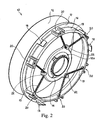
Fig. 2 is a perspective view of a weft-braking device according to the invention; -
Fig. 3 is a perspective view showing a component of the weft-braking device ofFig. 1 ; -
Fig. 4 is an exploded, perspective view showing a detail of the component ofFig. 3 to an enlarged scale. - A general yarn feeder YF of the type referred to by the present invention is diagrammatically shown in
Fig. 1 . Yarn feeder YF is provided with a stationary yarn-winding drum D, on which a motorized swivel arm A winds a plurality of loops of yarn F forming a stock. Upon request from a general textile machine arranged downstream (not shown), e.g., a conventional knitting machine, the loops are unwound from drum D, then pass through a weft-braking device 10 which is adapted to maintain the unwinding yarn slightly tensioned, and then are fed to the machine. - A weft-
braking device 10 according to the invention is shown in detail inFigs. 2-4 . Weft-braking device 10 generally comprises a hollow, frustoconical braking member orcone 12, which is coaxially supported in front of weft-winding drum D, as diagrammatically shown inFig. 1 , and is elastically biased with its inner surface against the delivery edge of the drum. To this purpose, as shown inFig. 2 , thesmaller base 12a ofcone 12 is coaxially attached to aring 14, which is supported at the middle of anannular support 16 via elastic means.Annular support 16 is adapted to be connected, in a way known per se, to an annular frame T (diagrammatically shown inFig. 1 ) which, in turn, is connected to the housing of the feeder. To this purpose,annular support 16 has aflange 17 formed at its axial end facing the drum, which is provided with threetoothed tabs 18 spaced at equal angles from each other and projecting longitudinally from its outer edge to engage corresponding seats (not shown) of annular frame T by snap fit. Annular frame T is typically attached to a mechanism M (diagrammatically shown inFig. 1 ) which allows the axial position ofannular support 16 with respect to drum D to be manually varied, in order to adjust the static pressure exerted bycone 12 against the edge of the drum. - According to the invention, the elastic means which connect
inner ring 14 to outerannular support 16 comprise a triad of elongated elastic members, which preferably consist ofhelical springs 19, each of which has both its ends anchored torespective anchor seats 20 ofannular support 16 which are arranged in pairs equally-spaced from each other, and has an intermediate portion that restrainedly engages a respective one of threeanchor projections 22 formed on thering 14 and spaced 120° from each other. - Preferably, all six
anchor seats 20 on outerannular support 16 are equally spaced 60° from each other. - Advantageously, both
inner ring 14 and outerannular support 16 are molded in a synthetic material, andanchor projections 22 are made enbloc withinner ring 14, as well asanchor seats 20 with outerannular support 16. -
Anchor projections 22 are in the shape of hooks projecting outwards. - A through opening in the shape of a
radial hole 24 is formed onannular support 16 at eachanchor seat 20, through which a corresponding end ofspring 19 is inserted. Two counterposed,longitudinal guides 26a, 26b having their upper ends bent at right angles inwards are formed at respective opposite sides ofhole 24.Guides 26a, 26b extend longitudinally fromflange 17 to the opposite axial end ofannular support 16. The ends ofsprings 19 are conventionally provided with eyelets 28 (Fig. 3 ).Eyelets 28 are anchored to theirrespective seats 20 via anchor members in the shape ofpins 30. The pins are inserted ineyelets 28, abut against the surface ofannular support 16 facing away from the side of insertion ofsprings 19, and engageguides 26a, 26b with their opposite ends. - In operation, the yarn runs between the drum and the braking member and, therefore, is subject to a braking action by friction, in a conventional way per se.
- However, with the weft-braking device according to the invention, connecting
springs 19 toannular support 16 viapins 30 is only required at first installation, after whichcone 12 can be fastened/unfastened more easily and more practically with respect to the conventional weft-braking devices (e.g., for replacement or cleaning purposes) by simply hooking/unhookingsprings 19 to/from hook-shaped projections 22 ofinner ring 14. - In addition, although the device according to the invention is only provided with three elastic members, it should be noted that they pull on the annular support in six points, for the benefit of a uniform distribution of the forces.
- Moreover, as the person skilled in the art will appreciate, with the device according to the invention
annular support 16 acts as a shield for the pointed ends of the springs, against the dust generated by the yarn running between the drum and the cone, thereby preventing heaps of dust from building up on the brake, with consequent drawbacks. - A preferred embodiment of the invention has been described herein, but of course many changes may been made by a person skilled in the art within the scope of the claims. In particular, the number of elastic members may be reduced to two or increased, e.g., to four or even more, depending on the circumstances. Although helical springs are used in the above-described example, other types of elongated, elastic members can be used, such as elastic ropes made of rubber, which could be provided with rigid, anchor ends in the shape of hooks or rings. Moreover, in the above-described example the opposite ends of each spring are anchored to two respective seats spaced from each other. However, both ends could be anchored to the same seat. Furthermore,
cone 12 could also be made enbloc withinner ring 14. Moreover, in the present description reference has always been made to a hollow, frustoconical braking member. However, it is obvious that the same system can be applied to circular braking members having different shapes, e.g., members in the shape of bell or dome, which may be made of either a continuous material, e.g., plastics, or a non-continuous material, e.g., bristles. In addition, the anchor ends ofsprings 19 are not necessarily required to be in the shape of eyelets, provided that they are bent to a restrainedly engageable shape, e.g., a hook shape. Furthermore, throughopenings 24 could also consist of recesses on one of the edges of annular support.
Claims (10)
- A weft-braking device for yarn feeders having a stationary drum, comprising a braking member having a circular profile (12), which is coaxially supported via elastic means at the middle of an annular support (16) connectable to said yarn feeder, and is adapted to be coaxially biased against the delivery edge of said stationary drum of the feeder for applying a braking action by friction to the yarn, characterized in that said elastic means comprise at least two elongated elastic members (19), which have both their ends anchored to said annular support (16), and have intermediate portions restrainedly engaged with respective anchor projections (22) integral with said braking member (12).
- The weft-braking device of claim 1, characterized in that said annular support is provided with anchoring seats (20) in which the ends of said elongated elastic members are restrained.
- The weft-braking device of claim 2, characterized in that, at each of said anchor seats (20), said annular support (16) has a through opening (24) in which one end of said elongated elastic member (19) is inserted, said end being anchored to an anchoring member (30) adapted to abut against the opposite surface of said annular support (16) with respect to the insertion side.
- The weft-braking device of claim 3, characterized in that said elongated elastic members (19) are provided with curved anchoring ends (28), and said anchoring member consists of a pin (30) engaging the respective curved anchoring end (28) and abutting with its opposite ends against said opposite surface of the annular support (16).
- The weft-braking device of claim 4, characterized in that said anchoring seats (20) each comprise two counterposed guides (26a, 26b) which longitudinally extend on said opposite surface of the annular support (16) at the opposite sides of the through opening (24), and are engaged by the opposed ends of said pin (30).
- The weft-braking device of any of claims 1 to 5, characterized in that said anchoring projections (22) are hook-shaped and are formed in one piece on a molded ring (14) made of a synthetic material, which is coaxially connected to the braking member (12).
- The weft-braking device of any of claims 2 to 6, characterized in that said anchoring projections (20) are arranged in pairs equally-spaced from each other.
- The weft-braking device of claim 7, characterized in that all of said anchoring seats (20) are equally-spaced from each other.
- The weft-braking device of any of claims 1 to 8, characterized in that it comprises three of said elongated elastic members (19).
- The weft-braking device of any of claims 1 to 9, characterized in that said elongated elastic members are helical springs (19).
Applications Claiming Priority (1)
| Application Number | Priority Date | Filing Date | Title |
|---|---|---|---|
| IT000875A ITTO20120875A1 (en) | 2012-10-09 | 2012-10-09 | MILLING-PLANE DEVICE FOR FIXED DRUM YARN FEEDERS. |
Publications (2)
| Publication Number | Publication Date |
|---|---|
| EP2719804A1 EP2719804A1 (en) | 2014-04-16 |
| EP2719804B1 true EP2719804B1 (en) | 2015-12-30 |
Family
ID=47138101
Family Applications (1)
| Application Number | Title | Priority Date | Filing Date |
|---|---|---|---|
| EP13003739.3A Active EP2719804B1 (en) | 2012-10-09 | 2013-07-26 | Weft-braking device for yarn feeders with stationary drum |
Country Status (3)
| Country | Link |
|---|---|
| EP (1) | EP2719804B1 (en) |
| CN (1) | CN103710821B (en) |
| IT (1) | ITTO20120875A1 (en) |
Cited By (1)
| Publication number | Priority date | Publication date | Assignee | Title |
|---|---|---|---|---|
| DE102016117506B3 (en) * | 2016-09-16 | 2017-11-23 | Memminger-Iro Gmbh | Yarn feeder |
Family Cites Families (8)
| Publication number | Priority date | Publication date | Assignee | Title |
|---|---|---|---|---|
| DE3446567C1 (en) * | 1984-12-20 | 1986-05-07 | Lindauer Dornier Gmbh, 8990 Lindau | Weft brake with gradually controllable braking effect |
| ES2110458T3 (en) * | 1991-09-20 | 1998-02-16 | Lgl Electronics Spa | SELF-ADJUSTABLE DEVICE TO BRAKE THREAD IN WEFT FEED UNITS. |
| IT1292765B1 (en) * | 1997-06-11 | 1999-02-11 | Lgl Electronics Spa | IMPROVEMENT ON SELF-REGULATED MODULATED YARN BRAKING DEVICES FOR WEFT FEEDING EQUIPMENT FOR TEXTILE MACHINES |
| IT1308067B1 (en) * | 1999-06-01 | 2001-11-29 | Lgl Electronics Spa | YARN BRAKING DEVICE, FOR WEFT FEEDER, WITH REDUCED INTERVENTION TIMES |
| ITTO20020023U1 (en) * | 2002-02-01 | 2003-08-01 | Lgl Electronics Spa | ,, BRAKE HOLDER HOLDER RETAINING DEVICE IN WEFT FEEDING DEVICES ,, |
| ITTO20050279A1 (en) * | 2005-04-27 | 2006-10-28 | Lgl Electronics Spa | YARN BRAKING DEVICE IN WEFT FEEDERS FOR TEXTILE MACHINES |
| CN201753388U (en) * | 2010-07-10 | 2011-03-02 | 严克明 | Yarn outlet tension control device for weft accumulator |
| CN102477653A (en) * | 2010-11-24 | 2012-05-30 | 大连创达技术交易市场有限公司 | Novel yarn braking device |
-
2012
- 2012-10-09 IT IT000875A patent/ITTO20120875A1/en unknown
-
2013
- 2013-07-26 EP EP13003739.3A patent/EP2719804B1/en active Active
- 2013-08-26 CN CN201310376209.3A patent/CN103710821B/en active Active
Cited By (2)
| Publication number | Priority date | Publication date | Assignee | Title |
|---|---|---|---|---|
| DE102016117506B3 (en) * | 2016-09-16 | 2017-11-23 | Memminger-Iro Gmbh | Yarn feeder |
| EP3296242A2 (en) | 2016-09-16 | 2018-03-21 | Memminger-IRO GmbH | Thread delivery device |
Also Published As
| Publication number | Publication date |
|---|---|
| CN103710821A (en) | 2014-04-09 |
| CN103710821B (en) | 2016-06-08 |
| EP2719804A1 (en) | 2014-04-16 |
| ITTO20120875A1 (en) | 2014-04-10 |
Similar Documents
| Publication | Publication Date | Title |
|---|---|---|
| EP3473761B1 (en) | Lace provided with tubular lace body | |
| EP2719804B1 (en) | Weft-braking device for yarn feeders with stationary drum | |
| EP3655611B1 (en) | Screen device | |
| CZ278749B6 (en) | Device for collecting and feeding threads, particularly for textile machines | |
| BE1008504A5 (en) | SECURE WINDING DEVICE FOR QUICK CONNECTION OF STRINGS WITH HARNESS lift cords on a weaving machine. | |
| EP2829647B1 (en) | Yarn feeder provided with a weft-winding drum and with a feedback-controlled, weft-braking device | |
| CN209522976U (en) | Compensation weft brake for textile application | |
| EP2147172B1 (en) | Rail for stretched cloth false wall | |
| JPS63256753A (en) | Yarn feeder for knitting machine | |
| CN1137845C (en) | Yarn brake, particularly for yarn feeders of looms | |
| CN1275959A (en) | Yarn braking device in yarn feeders for looms and brake element for said device | |
| US7025094B2 (en) | Device for attaching return springs in a harness of a Jacquard weaving machine | |
| EP1724384B1 (en) | Yarn-braking device in weft feeders for textile machines | |
| US10968069B2 (en) | Tube holder for line dispensing | |
| EP1717181B1 (en) | Yarn-braking device in weft feeders for textile machines | |
| KR102378500B1 (en) | Actual feed amount measuring device | |
| CN103726197A (en) | Weft feeding blade adjusting tool of weft length measurement and storage device | |
| EP1101851A1 (en) | Compensating weft brake | |
| JP5719253B2 (en) | Wiring / pipe material hanger, and straps for wiring / pipe material hanger | |
| US20210362975A1 (en) | Tube holder for line dispensing | |
| KR102767556B1 (en) | Tension-retaining rope railing | |
| WO2011104570A2 (en) | Apparatus for securing a curtain to a curtain rail | |
| CN212270359U (en) | Big circular knitting machine with yarn length appearance | |
| RU2773909C2 (en) | Holder of fiber dispensing tube | |
| EP3835469B1 (en) | Weft braking device for accumulator yarn feeders |
Legal Events
| Date | Code | Title | Description |
|---|---|---|---|
| PUAI | Public reference made under article 153(3) epc to a published international application that has entered the european phase |
Free format text: ORIGINAL CODE: 0009012 |
|
| AK | Designated contracting states |
Kind code of ref document: A1 Designated state(s): AL AT BE BG CH CY CZ DE DK EE ES FI FR GB GR HR HU IE IS IT LI LT LU LV MC MK MT NL NO PL PT RO RS SE SI SK SM TR |
|
| AX | Request for extension of the european patent |
Extension state: BA ME |
|
| 17P | Request for examination filed |
Effective date: 20140424 |
|
| RBV | Designated contracting states (corrected) |
Designated state(s): AL AT BE BG CH CY CZ DE DK EE ES FI FR GB GR HR HU IE IS IT LI LT LU LV MC MK MT NL NO PL PT RO RS SE SI SK SM TR |
|
| GRAP | Despatch of communication of intention to grant a patent |
Free format text: ORIGINAL CODE: EPIDOSNIGR1 |
|
| INTG | Intention to grant announced |
Effective date: 20150626 |
|
| GRAS | Grant fee paid |
Free format text: ORIGINAL CODE: EPIDOSNIGR3 |
|
| GRAA | (expected) grant |
Free format text: ORIGINAL CODE: 0009210 |
|
| AK | Designated contracting states |
Kind code of ref document: B1 Designated state(s): AL AT BE BG CH CY CZ DE DK EE ES FI FR GB GR HR HU IE IS IT LI LT LU LV MC MK MT NL NO PL PT RO RS SE SI SK SM TR |
|
| REG | Reference to a national code |
Ref country code: GB Ref legal event code: FG4D |
|
| REG | Reference to a national code |
Ref country code: CH Ref legal event code: EP |
|
| REG | Reference to a national code |
Ref country code: AT Ref legal event code: REF Ref document number: 767548 Country of ref document: AT Kind code of ref document: T Effective date: 20160115 |
|
| REG | Reference to a national code |
Ref country code: IE Ref legal event code: FG4D |
|
| REG | Reference to a national code |
Ref country code: DE Ref legal event code: R096 Ref document number: 602013004282 Country of ref document: DE |
|
| REG | Reference to a national code |
Ref country code: SE Ref legal event code: TRGR |
|
| REG | Reference to a national code |
Ref country code: LT Ref legal event code: MG4D |
|
| PG25 | Lapsed in a contracting state [announced via postgrant information from national office to epo] |
Ref country code: LT Free format text: LAPSE BECAUSE OF FAILURE TO SUBMIT A TRANSLATION OF THE DESCRIPTION OR TO PAY THE FEE WITHIN THE PRESCRIBED TIME-LIMIT Effective date: 20151230 Ref country code: NO Free format text: LAPSE BECAUSE OF FAILURE TO SUBMIT A TRANSLATION OF THE DESCRIPTION OR TO PAY THE FEE WITHIN THE PRESCRIBED TIME-LIMIT Effective date: 20160330 Ref country code: HR Free format text: LAPSE BECAUSE OF FAILURE TO SUBMIT A TRANSLATION OF THE DESCRIPTION OR TO PAY THE FEE WITHIN THE PRESCRIBED TIME-LIMIT Effective date: 20151230 |
|
| REG | Reference to a national code |
Ref country code: NL Ref legal event code: MP Effective date: 20151230 |
|
| REG | Reference to a national code |
Ref country code: AT Ref legal event code: MK05 Ref document number: 767548 Country of ref document: AT Kind code of ref document: T Effective date: 20151230 |
|
| PG25 | Lapsed in a contracting state [announced via postgrant information from national office to epo] |
Ref country code: LV Free format text: LAPSE BECAUSE OF FAILURE TO SUBMIT A TRANSLATION OF THE DESCRIPTION OR TO PAY THE FEE WITHIN THE PRESCRIBED TIME-LIMIT Effective date: 20151230 Ref country code: FI Free format text: LAPSE BECAUSE OF FAILURE TO SUBMIT A TRANSLATION OF THE DESCRIPTION OR TO PAY THE FEE WITHIN THE PRESCRIBED TIME-LIMIT Effective date: 20151230 Ref country code: RS Free format text: LAPSE BECAUSE OF FAILURE TO SUBMIT A TRANSLATION OF THE DESCRIPTION OR TO PAY THE FEE WITHIN THE PRESCRIBED TIME-LIMIT Effective date: 20151230 Ref country code: GR Free format text: LAPSE BECAUSE OF FAILURE TO SUBMIT A TRANSLATION OF THE DESCRIPTION OR TO PAY THE FEE WITHIN THE PRESCRIBED TIME-LIMIT Effective date: 20160331 |
|
| PG25 | Lapsed in a contracting state [announced via postgrant information from national office to epo] |
Ref country code: NL Free format text: LAPSE BECAUSE OF FAILURE TO SUBMIT A TRANSLATION OF THE DESCRIPTION OR TO PAY THE FEE WITHIN THE PRESCRIBED TIME-LIMIT Effective date: 20151230 |
|
| PG25 | Lapsed in a contracting state [announced via postgrant information from national office to epo] |
Ref country code: ES Free format text: LAPSE BECAUSE OF FAILURE TO SUBMIT A TRANSLATION OF THE DESCRIPTION OR TO PAY THE FEE WITHIN THE PRESCRIBED TIME-LIMIT Effective date: 20151230 Ref country code: CZ Free format text: LAPSE BECAUSE OF FAILURE TO SUBMIT A TRANSLATION OF THE DESCRIPTION OR TO PAY THE FEE WITHIN THE PRESCRIBED TIME-LIMIT Effective date: 20151230 |
|
| PG25 | Lapsed in a contracting state [announced via postgrant information from national office to epo] |
Ref country code: EE Free format text: LAPSE BECAUSE OF FAILURE TO SUBMIT A TRANSLATION OF THE DESCRIPTION OR TO PAY THE FEE WITHIN THE PRESCRIBED TIME-LIMIT Effective date: 20151230 Ref country code: SK Free format text: LAPSE BECAUSE OF FAILURE TO SUBMIT A TRANSLATION OF THE DESCRIPTION OR TO PAY THE FEE WITHIN THE PRESCRIBED TIME-LIMIT Effective date: 20151230 Ref country code: IS Free format text: LAPSE BECAUSE OF FAILURE TO SUBMIT A TRANSLATION OF THE DESCRIPTION OR TO PAY THE FEE WITHIN THE PRESCRIBED TIME-LIMIT Effective date: 20160430 Ref country code: AT Free format text: LAPSE BECAUSE OF FAILURE TO SUBMIT A TRANSLATION OF THE DESCRIPTION OR TO PAY THE FEE WITHIN THE PRESCRIBED TIME-LIMIT Effective date: 20151230 Ref country code: PL Free format text: LAPSE BECAUSE OF FAILURE TO SUBMIT A TRANSLATION OF THE DESCRIPTION OR TO PAY THE FEE WITHIN THE PRESCRIBED TIME-LIMIT Effective date: 20151230 Ref country code: SM Free format text: LAPSE BECAUSE OF FAILURE TO SUBMIT A TRANSLATION OF THE DESCRIPTION OR TO PAY THE FEE WITHIN THE PRESCRIBED TIME-LIMIT Effective date: 20151230 Ref country code: RO Free format text: LAPSE BECAUSE OF FAILURE TO SUBMIT A TRANSLATION OF THE DESCRIPTION OR TO PAY THE FEE WITHIN THE PRESCRIBED TIME-LIMIT Effective date: 20151230 Ref country code: PT Free format text: LAPSE BECAUSE OF FAILURE TO SUBMIT A TRANSLATION OF THE DESCRIPTION OR TO PAY THE FEE WITHIN THE PRESCRIBED TIME-LIMIT Effective date: 20160502 |
|
| REG | Reference to a national code |
Ref country code: DE Ref legal event code: R097 Ref document number: 602013004282 Country of ref document: DE |
|
| PG25 | Lapsed in a contracting state [announced via postgrant information from national office to epo] |
Ref country code: DK Free format text: LAPSE BECAUSE OF FAILURE TO SUBMIT A TRANSLATION OF THE DESCRIPTION OR TO PAY THE FEE WITHIN THE PRESCRIBED TIME-LIMIT Effective date: 20151230 |
|
| PLBE | No opposition filed within time limit |
Free format text: ORIGINAL CODE: 0009261 |
|
| STAA | Information on the status of an ep patent application or granted ep patent |
Free format text: STATUS: NO OPPOSITION FILED WITHIN TIME LIMIT |
|
| 26N | No opposition filed |
Effective date: 20161003 |
|
| PG25 | Lapsed in a contracting state [announced via postgrant information from national office to epo] |
Ref country code: SI Free format text: LAPSE BECAUSE OF FAILURE TO SUBMIT A TRANSLATION OF THE DESCRIPTION OR TO PAY THE FEE WITHIN THE PRESCRIBED TIME-LIMIT Effective date: 20151230 |
|
| REG | Reference to a national code |
Ref country code: CH Ref legal event code: PL |
|
| PG25 | Lapsed in a contracting state [announced via postgrant information from national office to epo] |
Ref country code: MC Free format text: LAPSE BECAUSE OF FAILURE TO SUBMIT A TRANSLATION OF THE DESCRIPTION OR TO PAY THE FEE WITHIN THE PRESCRIBED TIME-LIMIT Effective date: 20151230 |
|
| PG25 | Lapsed in a contracting state [announced via postgrant information from national office to epo] |
Ref country code: CH Free format text: LAPSE BECAUSE OF NON-PAYMENT OF DUE FEES Effective date: 20160731 Ref country code: FR Free format text: LAPSE BECAUSE OF NON-PAYMENT OF DUE FEES Effective date: 20160801 Ref country code: LI Free format text: LAPSE BECAUSE OF NON-PAYMENT OF DUE FEES Effective date: 20160731 |
|
| REG | Reference to a national code |
Ref country code: FR Ref legal event code: ST Effective date: 20170331 |
|
| REG | Reference to a national code |
Ref country code: IE Ref legal event code: MM4A |
|
| PG25 | Lapsed in a contracting state [announced via postgrant information from national office to epo] |
Ref country code: IE Free format text: LAPSE BECAUSE OF NON-PAYMENT OF DUE FEES Effective date: 20160726 |
|
| PG25 | Lapsed in a contracting state [announced via postgrant information from national office to epo] |
Ref country code: LU Free format text: LAPSE BECAUSE OF NON-PAYMENT OF DUE FEES Effective date: 20160726 |
|
| PG25 | Lapsed in a contracting state [announced via postgrant information from national office to epo] |
Ref country code: HU Free format text: LAPSE BECAUSE OF FAILURE TO SUBMIT A TRANSLATION OF THE DESCRIPTION OR TO PAY THE FEE WITHIN THE PRESCRIBED TIME-LIMIT; INVALID AB INITIO Effective date: 20130726 Ref country code: CY Free format text: LAPSE BECAUSE OF FAILURE TO SUBMIT A TRANSLATION OF THE DESCRIPTION OR TO PAY THE FEE WITHIN THE PRESCRIBED TIME-LIMIT Effective date: 20151230 |
|
| PG25 | Lapsed in a contracting state [announced via postgrant information from national office to epo] |
Ref country code: MT Free format text: LAPSE BECAUSE OF NON-PAYMENT OF DUE FEES Effective date: 20160731 Ref country code: MK Free format text: LAPSE BECAUSE OF FAILURE TO SUBMIT A TRANSLATION OF THE DESCRIPTION OR TO PAY THE FEE WITHIN THE PRESCRIBED TIME-LIMIT Effective date: 20151230 |
|
| PG25 | Lapsed in a contracting state [announced via postgrant information from national office to epo] |
Ref country code: BG Free format text: LAPSE BECAUSE OF FAILURE TO SUBMIT A TRANSLATION OF THE DESCRIPTION OR TO PAY THE FEE WITHIN THE PRESCRIBED TIME-LIMIT Effective date: 20151230 |
|
| PG25 | Lapsed in a contracting state [announced via postgrant information from national office to epo] |
Ref country code: AL Free format text: LAPSE BECAUSE OF FAILURE TO SUBMIT A TRANSLATION OF THE DESCRIPTION OR TO PAY THE FEE WITHIN THE PRESCRIBED TIME-LIMIT Effective date: 20151230 |
|
| PGFP | Annual fee paid to national office [announced via postgrant information from national office to epo] |
Ref country code: SE Payment date: 20190620 Year of fee payment: 7 |
|
| REG | Reference to a national code |
Ref country code: SE Ref legal event code: EUG |
|
| PG25 | Lapsed in a contracting state [announced via postgrant information from national office to epo] |
Ref country code: SE Free format text: LAPSE BECAUSE OF NON-PAYMENT OF DUE FEES Effective date: 20200727 |
|
| PGFP | Annual fee paid to national office [announced via postgrant information from national office to epo] |
Ref country code: DE Payment date: 20250714 Year of fee payment: 13 |
|
| PGFP | Annual fee paid to national office [announced via postgrant information from national office to epo] |
Ref country code: TR Payment date: 20250722 Year of fee payment: 13 Ref country code: IT Payment date: 20250620 Year of fee payment: 13 |
|
| PGFP | Annual fee paid to national office [announced via postgrant information from national office to epo] |
Ref country code: BE Payment date: 20250714 Year of fee payment: 13 Ref country code: GB Payment date: 20250710 Year of fee payment: 13 |