EP2719754A1 - Image processing apparatus, image processing method and image processing system - Google Patents
Image processing apparatus, image processing method and image processing system Download PDFInfo
- Publication number
- EP2719754A1 EP2719754A1 EP11867361.5A EP11867361A EP2719754A1 EP 2719754 A1 EP2719754 A1 EP 2719754A1 EP 11867361 A EP11867361 A EP 11867361A EP 2719754 A1 EP2719754 A1 EP 2719754A1
- Authority
- EP
- European Patent Office
- Prior art keywords
- image
- feature amount
- rectangular area
- image processing
- target cell
- Prior art date
- Legal status (The legal status is an assumption and is not a legal conclusion. Google has not performed a legal analysis and makes no representation as to the accuracy of the status listed.)
- Granted
Links
Images




Classifications
-
- H—ELECTRICITY
- H04—ELECTRIC COMMUNICATION TECHNIQUE
- H04N—PICTORIAL COMMUNICATION, e.g. TELEVISION
- H04N7/00—Television systems
- H04N7/18—Closed-circuit television [CCTV] systems, i.e. systems in which the video signal is not broadcast
-
- G—PHYSICS
- G06—COMPUTING OR CALCULATING; COUNTING
- G06V—IMAGE OR VIDEO RECOGNITION OR UNDERSTANDING
- G06V20/00—Scenes; Scene-specific elements
- G06V20/60—Type of objects
- G06V20/69—Microscopic objects, e.g. biological cells or cellular parts
- G06V20/695—Preprocessing, e.g. image segmentation
-
- G—PHYSICS
- G06—COMPUTING OR CALCULATING; COUNTING
- G06T—IMAGE DATA PROCESSING OR GENERATION, IN GENERAL
- G06T7/00—Image analysis
- G06T7/10—Segmentation; Edge detection
- G06T7/11—Region-based segmentation
-
- G—PHYSICS
- G06—COMPUTING OR CALCULATING; COUNTING
- G06T—IMAGE DATA PROCESSING OR GENERATION, IN GENERAL
- G06T7/00—Image analysis
- G06T7/10—Segmentation; Edge detection
- G06T7/136—Segmentation; Edge detection involving thresholding
-
- G—PHYSICS
- G06—COMPUTING OR CALCULATING; COUNTING
- G06T—IMAGE DATA PROCESSING OR GENERATION, IN GENERAL
- G06T2207/00—Indexing scheme for image analysis or image enhancement
- G06T2207/10—Image acquisition modality
- G06T2207/10056—Microscopic image
-
- G—PHYSICS
- G06—COMPUTING OR CALCULATING; COUNTING
- G06T—IMAGE DATA PROCESSING OR GENERATION, IN GENERAL
- G06T2207/00—Indexing scheme for image analysis or image enhancement
- G06T2207/30—Subject of image; Context of image processing
- G06T2207/30004—Biomedical image processing
- G06T2207/30024—Cell structures in vitro; Tissue sections in vitro
Definitions
- the present invention relates to an image processing device, an image processing method, and an image processing system.
- NRBCs nucleated red blood cells
- target cells nucleated red blood cells derived from the fetus and included in extremely minute amounts in uterine blood. Since the number of NRBCs existing in the maternal blood is extremely small, visual detection of NRBCs imposes a heavy strain. Therefore, as described in PTL 1 below, there has been proposed a technology for mechanically detecting NRBCs by searching the target image for a cell satisfying conditions such as colors, shapes, positional relationships, or area ratios of NRBCs.
- Patent Literature 1 Japanese Patent No. 4,346,923
- An object of the present invention is to provide an image processing device, an image processing method, and an image processing system each capable of making it difficult to be affected by a difference between specimens of the target cells and a difference in imaging conditions and so on in the case of searching a taken image, which is obtained by imaging the target calls having a nucleus, for the target cells using image processing.
- the invention according to Claim 1 is an image processing device characterized by including acquisition means adapted to obtain a taken image obtained by imaging a sample including a target cell having a nucleus, first extraction means adapted to extract pixels to be a candidate of the nucleus from pixels included in the taken image based on a first condition determined in advance with respect to at least one of a color and a luminance, which the pixels to be the candidate are required to have, second extraction means adapted to extract a connected pixel group to be a candidate of the target cell from connected pixel groups, each of which is obtained by connecting adjacent ones of the pixels extracted by the first extraction means, based on a second condition determined in advance with respect to a size and a shape, which the connected pixel group to be the candidate is required to have, setting means adapted to set a rectangular area, which has a predetermined size and is centered on a pixel included in the connected pixel group extracted by the second extraction means, to the taken image, and determination means adapted to determine whether or not
- the invention according to Claim 2 is the image processing device according to Claim 1, characterized in that the condition of the image feature amount is mechanically learned based on sample images of a positive example and a negative example of the target cell.
- the invention according to Claim 3 is the image processing device according to one of Claims 1 and 2, characterized by further including calculation means adapted to calculate the image feature amount obtained from the rectangular area by dividing the rectangular area set by the setting means into predetermined partial areas, calculating a direction of a luminance gradient in each of the pixels in each of the partial areas, calculating a histogram of luminance gradient directions calculated with respect to each of the partial areas, and connecting the histograms of the respective partial areas.
- the invention according to Claim 4 is the image processing device according to any one of Claims 1 through 3, characterized in that the image feature amount is an HOG feature amount.
- the invention according to Claim 5 is the image processing device according to any one of Claims 1 through 4, characterized by further including image feature amount acquisition means adapted to rotate the taken image included in the rectangular area so that a vector connecting a center of the rectangular area set by the setting means and a centroid position of the connected pixel group included in the rectangular area points to a predetermined direction, and then obtain the image feature amount from the taken image rotated, and characterized in that the determination means determines whether or not the target cell is included in the rectangular area based on whether or not the image feature amount obtained by the image feature amount acquisition means satisfies the condition of the image feature amount.
- the invention according to Claim 6 is the image processing device according to any one of Claims 1 through 5, characterized by further including interpolation means adapted to perform interpolation, in a case in which an end of the taken image is included in the rectangular area set by the setting means, by combining an image, which is located on an outer side from a center line set in the connected pixel group included in the rectangular area than an area symmetrical to the end about the center line, to the end side in the image included in the rectangular area.
- the invention according to Claim 7 is the image processing device according to any one of Claims 1 through 6, characterized in that a coordinate area of the taken image corresponding to the rectangular area determined to include the target cell by the determination means is displayed on a display device.
- the invention according to Claim 8 is an image processing method characterized by including an acquisition step adapted to obtain a taken image obtained by imaging a sample including a target cell having a nucleus, a first extraction step adapted to extract pixels to be a candidate of the nucleus from pixels included in the taken image based on a first condition determined in advance with respect to at least one of a color and a luminance, which the pixels to be the candidate are required to have, a second extraction step adapted to extract a connected pixel group to be a candidate of the target cell from connected pixel groups, each of which is obtained by connecting adjacent ones of the pixels extracted in the first extraction step, based on a second condition determined in advance with respect to a size and a shape, which the connected pixel group to be the candidate is required to have, a setting step adapted to set a rectangular area, which has a predetermined size and is centered on a pixel included in the connected pixel group extracted in the second extraction step, to the taken image, and a determination step adapted to determine whether
- the invention according to Claim 9 is the image processing method according to Claim 8, characterized in that the condition of the image feature amount is mechanically learned based on sample images of a positive example and a negative example of the target cell.
- the invention according to Claim 10 is the image processing method according to one of Claims 8 and 9, characterized by further including a calculation step adapted to calculate the image feature amount obtained from the rectangular area by dividing the rectangular area set in the setting step into predetermined partial areas, calculating a direction of a luminance gradient in each of the pixels in each of the partial areas, calculating a histogram of luminance gradient directions calculated with respect to each of the partial areas, and connecting the histograms of the respective partial areas.
- the invention according to Claim 11 is the image processing method according to any one of Claims 8 through 10, characterized in that the image feature amount is an HOG feature amount.
- the invention according to Claim 12 is an image processing system characterized by including an image processing device, an optical microscope to be connected to the image processing device, and a display device to be connected to the image processing device, and characterized in that the image processing device includes acquisition means adapted to obtain a taken image obtained by imaging a sample including a target cell having a nucleus, first extraction means adapted to extract pixels to be a candidate of the nucleus from pixels included in the taken image based on a first condition determined in advance with respect to at least one of a color and a luminance, which the pixels to be the candidate are required to have, second extraction means adapted to extract a connected pixel group to be a candidate of the target cell from connected pixel groups, each of which is obtained by connecting adjacent ones of the pixels extracted by the first extraction means, based on a second condition determined in advance with respect to a size and a shape, which the connected pixel group to be the candidate is required to have, setting means adapted to set a rectangular area, which has a predetermined size and is centered
- the invention according to Claim 13 is the image processing system according to Claim 12 characterized in that the condition of the image feature amount is mechanically learned based on sample images of a positive example and a negative example of the target cell.
- the invention according to Claim 14 is the image processing system according to one of Claims 12 and 13, characterized by further including calculation means adapted to calculate the image feature amount obtained from the rectangular area by dividing the rectangular area set by the setting means into predetermined partial areas, calculating a direction of a luminance gradient in each of the pixels in each of the partial areas, calculating a histogram of luminance gradient directions calculated with respect to each of the partial areas, and connecting the histograms of the respective partial areas.
- the invention according to Claim 15 is the image processing system according to any one of Claims 12 through 14, characterized in that the image feature amount is an HOG feature amount.
- whether or not the target cell is included in the taken image can be determined with accuracy compared to the case in which the condition of the image feature amount is not learned based on the sample images of the positive example and the negative example of the target cell.
- the influence of the difference between the specimens of the target cell and the difference in imaging conditions and so on on the image feature amount obtained form the rectangular area is reduced compared to the case in which the HOG feature amount is not used as the image feature amount.
- the image area including the target cell can be displayed.
- Fig. 1 shows a system configuration diagram of an image processing system 1 according to the present embodiment.
- the image processing system 1 includes an optical microscope 2, an image processing device 10, and a display device 6, wherein the image processing device 10 is connected to each of the optical microscope 2 and the display device 6 so as to be able to perform data communication with each other.
- the optical microscope 2 takes an image of a sample on a glass slide 3 disposed on a stage via an optical system such as an objective lens 4 using a CCD camera 5.
- an optical system such as an objective lens 4 using a CCD camera 5.
- the sample what is obtained by applying the maternal blood on the glass slide 3 and then applying May-Giemsa stain is used as the sample.
- the fetus-derived nucleated red blood cells (NRBCs) in the maternal blood are stained to have a bluish-purple color.
- NRBCs are referred to as target cells.
- the image processing device 10 obtains the taken image taken by the optical microscope 2, and at the same time searches the taken image thus obtained for the target cells. The details of the search process for the target cells performed in the image processing device 10 will be described later.
- the display device 6 displays the image based on the result of the process by the image processing device 10. For example, on the display device 6, there are displayed the taken image taken by the optical microscope 2, the search result of the target cells by the image processing device 10, and so on.
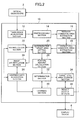
- Fig. 2 shows a functional block diagram of the image processing device 10.
- the image processing device 10 is provided with a taken image acquisition section 12, a preprocessing section 14, a nucleus candidate area extraction section 16, a target cell candidate area extraction section 18, a determination target area setting section 20, a normalization section 22, an image interpolation section 24, a feature amount calculation section 26, a learning data acquisition section 28, a learning section 30, a determination section 32, a target cell area storage section 34, and a result output section 36.
- the functions of the respective sections described above provided to the image processing device 10 may be realized by a computer, which is provided with a control means such as a CPU, a storage means such as a memory, an input/output means for transmitting/receiving data with an external device, and so on, reading and then executing a program stored in a computer-readable information storage medium.
- the program may be supplied to the image processing device 10 as the computer by the information storage medium such as an optical disk, a magnetic disk, a magnetic tape, a magneto optical disk, or a flash memory, or the program may be supplied to the image processing device 10 via a data communication network such as the Internet.
- the taken image acquisition section 12 obtains the taken image, which is obtained by imaging the sample with the CCD camera 5 provided to the optical microscope 2, from the optical microscope 2.
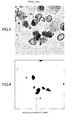
- Fig. 3 shows an example of the taken image, which is obtained by imaging the sample (the maternal blood) with the optical microscope 2, obtained by the taken image acquisition section 12.
- a cell having a deeply-colored nucleus is the target cell.
- the target cells each have the following four features (see “ Automated Extraction of Nucleated Red Blood Cells from Considerable Microscope Images," The Journal of the Institute of Image Electronics Engineers of Japan, vol. 37, No. 5, Sep. 2008 ).
- the first feature of NRBCs is the point that a single nucleus exists in each of NRBCs, the shape of the nucleus is an almost true circle, and the density is high.
- the second feature is the point that the nucleus of NRBCs is stained by the May-Giemsa stain slightly deeper than nuclei of other cells.
- the third feature is the point that the area of each of NRBCs and the area of the nucleus, and the ratio between the areas each fall within a specific range.
- the fourth feature is the point that NRBCs have a slightly larger difference in concentration between the nucleus and the cytoplasm compared to other cells.
- the preprocessing section 14 performs image processing such as histogram normalization, color matching by a principal component analysis, mean filter, or median filter on the taken image obtained by the taken image acquisition section 12 to thereby perform the normalization of the color of the taken image and noise removal.
- image processing such as histogram normalization, color matching by a principal component analysis, mean filter, or median filter on the taken image obtained by the taken image acquisition section 12 to thereby perform the normalization of the color of the taken image and noise removal.
- the nucleus candidate area extraction section 16 extracts the pixels having a color or a concentration included in a predetermined range as candidate areas of the nucleus with respect to the taken image from which noise is removed by the preprocessing section 14. For example, the nucleus candidate area extraction section 16 may binarize the pixels in the taken image using a predetermined threshold value of the color (or the concentration), and specifically, the pixels having the color (or the concentration) deeper (higher) than the threshold value (or equal to or higher than the threshold value) may be extracted as black pixels.
- Fig. 4 shows an example of the pixels of the nucleus candidates extracted by the nucleus candidate area extraction section 16 with respect to the taken image shown in Fig. 3 .
- the areas (the pixels) to be the candidate of the nucleus are extracted from the taken image.
- the target cell candidate area extraction section 18 extracts the connected pixel groups each having a vertical length, a horizontal length, and a ratio between the vertical length and the horizontal length of the circumscribed rectangle, and a black pixel density in the circumscribed rectangle each included in a range determined in advance for each of the values.
- Fig. 5 shows an example of the pixel groups extracted as the candidates of the target cell from the pixels of the nucleus candidates shown in Fig. 4 .
- the image areas each having a possibility of the nucleus in the target cell are further extracted from the nucleus candidates.
- the determination target area setting section 20 sets a rectangular area (a determination target rectangular area) having a predetermined size (e.g., N ⁇ M pixels) centered on the pixel of the rectangular area (a candidate rectangular area), which is set to the connected pixel group extracted by the target cell candidate area extraction section 18, to the taken image. For example, the determination target area setting section 20 selects one pixel from the candidate rectangular area, then identifies the corresponding pixel in the taken image based on the positional coordinate of the one pixel thus selected, and then sets the determination target rectangular area having a predetermined size centered on the corresponding pixel thus identified. It should be noted that the determination target area setting section 20 sequentially may select one pixel from the candidate rectangular area, and then set the determination target area for every selected pixel.
- a predetermined size e.g., N ⁇ M pixels
- Fig. 6 shows an example of the determination target area set in the taken image by the determination target area setting section 20. As shown in Fig. 6 , the determination target area is set centered on one pixel in the candidate rectangular area.
- the normalization section 22 performs a process of rotating the image in the determination target area set by the determination target area setting section 20 so that the direction of the image coincides with a predetermined direction. For example, the normalization section 22 obtains a centroid position of the binarized image in the determination target area, and then calculates a rotational angle necessary for a directional vector, which connects the center position of the determination target area and the centroid position obtained as described above, to point to a predetermined direction (e.g., an upward direction). Then, the normalization section 22 rotates the image (a partial image of the taken image) in the determination target area at the rotational angle calculated as described above. It should be noted that the process by the normalization section 22 is not necessarily required to be performed.
- Fig. 7 shows diagrams for explaining the flow of the process by the normalization section 22.
- Fig. 7(A) is the determination target area set in the taken image
- Fig. 7 (B) is the binarized image in the determination target area.
- Fig. 7(C) is the image obtained by rotating the taken image shown in Fig. 7(A) at the rotational angle ⁇ necessary for the directional vector of Fig. 7(B) to point to the upward direction, and then cutting the taken image with the determination target area.
- the image interpolation section 24 interpolates the image in the determination target area. For example, the image interpolation section 24 expands the determination target area so as to have a predetermined size (2M ⁇ 2M), and then sets the longest part of line segments, which are parallel to the end of the taken image in the binarized image included in the determination target area thus expanded, to the center line.
- the image interpolation section 24 obtains the distance L from the center line thus set to the end of the taken image, and then moves a partial area, which is composed of (M-L) pixels perpendicular to the center line, and 2M pixels parallel to the center line, from the end opposed to the end of the taken image with respect to the center line to the position line symmetrical about the center line in the area thus expanded to thereby interpolate the image in the determination target area.
- Fig. 8 shows diagrams for explaining the flow of the process by the image interpolation section 24.
- Fig. 8 (A) is an example of the determination target area set by the determination target area setting section 20, and as shown in Fig. 8(A) , the determination target area includes the end of the taken image.
- the image interpolation section 24 expands the determination target area so as to have a size of 2Mx2M, and then sets the position of a line segment, which is parallel to the end of the taken image and the longest of the binarized image in the determination target area, as the center line. Then, the image interpolation section 24 obtains (see Fig.
- the feature amount calculation section 26 calculates the image feature amount with respect to the image (the image is preferably normalized by the normalization section, but an image on which no normalization process is performed can also be adopted) in the determination target area set by the determination target area setting section 20.
- the HOG feature amount may be used for the image feature amount.
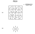
- Fig. 9 shows diagrams for explaining the HOG feature amount calculated by the feature amount calculation section 26.
- the HOG feature amount is calculated by dividing the determination target area into a predetermined number (e.g., 4x4) of partial areas, calculating a direction of a luminance gradient in each of the pixels in each of the partial areas, calculating a histogram of the luminance gradient direction thus calculated with respect to each of the partial areas, and connecting the histograms of the respective partial areas to each other.
- the luminance gradient directions may be, for example, the 8 directions (upper, upper right, lower right, right, lower, lower left, left, and upper left).
- the learning data acquisition section 28 obtains sample images of a positive example and a negative example of the target cell, and then obtains the image feature amount with respect to each of the sample images of the positive example and the negative example thus obtained.
- the HOG feature amount may be calculated with the feature amount calculation section 26 with respect to the sample images, and the learning data acquisition section 28 may obtain the result.
- the learning section 30 learns the conditions (criteria) of the image feature amount for distinguishing the target cell from others based on the image feature amount of each of the positive example and the negative example obtained by the learning data acquisition section 28. It should be noted that the learning may be performed using a learning algorithm such as Support Vector Machine or AdaBoost. For example, in the case of using the Support Vector Machine for the learning, the condition of the image feature amount to be learned is represented by a hyperplane for separating the image feature amount coinciding with the target cell and the image feature amount failing to coincide with the target cell from each other.
- the determination section 32 determines whether or not the image in a determination target area described above represents the target cell based on whether or not the image feature amount, which is calculated by the feature amount calculation section 26 with respect to the image in the determination target area set by the determination target area setting section 20, satisfies the condition of the image feature amount for distinguishing the target cell learned by the learning section 30 from others.
- the target cell area storage section 34 stores a coordinate range in the taken image corresponding to the determination target area determined to include the target cell by the determination section 32. It should be noted that it is also possible to arrange that the target cell area storage section 34 stores the part, where a plurality of determination target areas determined to include the target cell overlap each other, as an existing area of the target cell.
- the result output section 36 outputs the result based on the coordinate range of the taken image stored in the target cell area storage section 34.
- the result output section 36 may perform the process of making the display device 6 display the image for displaying the coordinate range of the taken image stored in the target cell area storage section 34, or moving the imaging position of the optical microscope 2 to the coordinate range.
- Fig. 10 shows a flowchart of a learning process of the image feature amount performed based on the positive example and the negative example of the target cell.
- the image processing device 10 obtains (S101) the positive example image of the target cell, and then calculates the image feature amount (the HOG feature amount) from the positive example image thus obtained to thereby generate (S102) the learning data of the positive example.
- the image processing device 10 obtains (S103) the negative example image of the target cell, and then calculates the image feature amount (the HOG feature amount) from the negative example image thus obtained to thereby generate (S104) the learning data of the negative example.
- the image processing device 10 learns (S105) a state (a model parameter) of a discriminator for discriminating the image feature amount of the target cell based on the learning data of the positive example and the learning data of the negative example, then stores (S106) the model parameter thus learned, and then terminates the learning process.
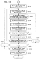
- the image processing device 10 obtains (S201) the taken image obtained by imaging the maternal blood with the optical microscope 2, and then performs (S202) the preprocessing such as the median filter on the taken image thus obtained. Further, the image processing device 10 generates (S203) the binarized image in which the pixels each having a color (e.g., RGB values) within a predetermined range are set to 1 (black pixels) and the other pixels are set to 0 (white pixels) with respect to the taken image on which the preprocessing has been performed.
- the black pixels in the binarized image represent the candidate area of the nucleus.
- the image processing device 10 connects the pixels adjacent to each other among the black pixels in the binarized image to thereby generate the connected pixel groups, and then performs (S204) the labeling of the connected pixel groups.
- the image processing device 10 selects (S205, the connected pixel group selected here is denoted with Li, and the initial value of i is 1) one of the connected pixel groups thus labeled, and then determines (S206) whether or not the size and the shape of the circumscribed rectangle set with respect to Li satisfy the conditions, which should be satisfied by the candidate of the target cell.
- Li is set (S207) as the search target area for the target cell.
- Li is not set (S208) as the search target area for the target cell.
- the image processing device 10 increments (S210) i, and then returns to S206. In the case in which no unselected connected pixel group remains (S209:N), the image processing device 10 proceeds to S211.
- the image processing device 10 selects (S211, the search target area selected here is denoted with Aj, and the initial value of j is 1) one of the search target areas (A1 through Am) set as described above, and further selects (S212) unselected one of the pixels in the circumscribed rectangle of Aj.
- the image processing device 10 sets (S213) the rectangular area (the determination target area: size S, an initial value of S is equal to Smin), which has a predetermined size centered on the pixel selected as described above, to the taken image, then normalizes (S214) the direction of the image of the determination target area thus set, and further performs (S215) the image interpolation process in the case in which the distance from the center of the determination target area to the end of the taken image is shorter than the threshold value (i.e., the case in which the determination target area is cut at the end of the taken image).
- the threshold value i.e., the case in which the determination target area is cut at the end of the taken image.
- the image processing device 10 calculates (S216) the image feature amount of the image included in the determination target area set as described above, determines (S217) whether or not the target cell is included in the determination target area based on the image feature amount thus calculated and the model parameter of the discriminator for discriminating the image feature amount of the target cell learned in advance, and in the case in which it is determined that the target cell is included (S217:Y), stores (S218) the coordinate range of the taken image corresponding to the determination target area.
- the image processing device 10 After S218, or in the case in which it is determined in S217 that the target cell is not included (S217:N), in the case in which any unprocessed pixel remains in the pixels within the circumscribed rectangle of Aj (S219:Y), the image processing device 10 returns to S212, or in the case in which no unprocessed pixel remains (S219:N), the image processing device 10 determines (S220) whether or not the size S of the determination target area has reached Smax (>Smin).
- the image processing device 10 increase (S221) S by ⁇ S, and then returns to S213, or in the case in which the size S of the determination target area has reached Smax (S220:Y), proceeds to S222.
- the image processing device 10 increments (S223) j of Aj, then returns to S212. In the case in which all of the search target areas have been processed (S222:Y), the image processing device 10 displays (S224) the coordinate range of the taken image, which has been determined to include the target cell, and then terminates the process.
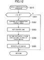
- the image processing device 10 expands (S302) the area based on the end of the taken image so that the length of each side becomes M+M pixels, and then sets (S303) the longest part of line segments, which are parallel to the end of the taken image in the binarized image included in the area thus expanded, to the center line.
- the image processing device 10 obtains (S304) the distance L from the center line thus set to the end of the taken image, and then moves a partial area, which is composed of (M-L) pixels perpendicular to the center line, and 2M pixels parallel to the center line, from the end opposed to the end of the taken image with respect to the center line to the position line symmetrical about the center line in the area thus expanded to thereby interpolate (S305) the image in the determination target area. After S305, or in the case in which the distance (d) from the center of the determination target area to the end of the taken image is equal to or longer than the threshold value (S301:Y), the image processing device 10 returns.
- the determination target areas are set based on the result of a second refinement further performed on the candidates obtained by the first refinement with the size and the shape of NRBCs, and then whether or not NRBCs are included in the determination target areas is determined by comparing the image feature amount obtained from the determination target area and the criterion obtained by learning based on the positive example and the negative example of NRBCs with each other, it becomes difficult to be affected by the difference between the specimens of the maternal blood and the difference in imaging conditions and so on while easing the burden on the process for detecting NRBCs included in the maternal blood compared to the case of performing the pattern matching on each of the candidates of the cells.
- the invention is not limited to the embodiment described above.
- the image processing system 1 in which the taken image of the sample is sequentially input from the optical microscope 2
- the image processing device 10 receives a search request for the target cell in the taken image from an information processing device via the communication network, and then returns the search result to the information processing device.
Landscapes
- Engineering & Computer Science (AREA)
- Physics & Mathematics (AREA)
- Theoretical Computer Science (AREA)
- General Physics & Mathematics (AREA)
- Computer Vision & Pattern Recognition (AREA)
- Multimedia (AREA)
- General Health & Medical Sciences (AREA)
- Molecular Biology (AREA)
- Health & Medical Sciences (AREA)
- Biomedical Technology (AREA)
- Life Sciences & Earth Sciences (AREA)
- Signal Processing (AREA)
- Image Processing (AREA)
- Image Analysis (AREA)
- Investigating Or Analysing Materials By Optical Means (AREA)
- Apparatus Associated With Microorganisms And Enzymes (AREA)
- Measuring Or Testing Involving Enzymes Or Micro-Organisms (AREA)
Abstract
Description
- The present invention relates to an image processing device, an image processing method, and an image processing system.
- In the case of performing prenatal diagnosis of a fetus, it is performed to detect and use nucleated red blood cells (NRBCs, hereinafter referred to as target cells) derived from the fetus and included in extremely minute amounts in uterine blood. Since the number of NRBCs existing in the maternal blood is extremely small, visual detection of NRBCs imposes a heavy strain. Therefore, as described in PTL 1 below, there has been proposed a technology for mechanically detecting NRBCs by searching the target image for a cell satisfying conditions such as colors, shapes, positional relationships, or area ratios of NRBCs.
- Patent Literature 1: Japanese Patent No.
4,346,923 - An object of the present invention is to provide an image processing device, an image processing method, and an image processing system each capable of making it difficult to be affected by a difference between specimens of the target cells and a difference in imaging conditions and so on in the case of searching a taken image, which is obtained by imaging the target calls having a nucleus, for the target cells using image processing.
- In order to achieve the object described above, the invention according to Claim 1 is an image processing device characterized by including acquisition means adapted to obtain a taken image obtained by imaging a sample including a target cell having a nucleus, first extraction means adapted to extract pixels to be a candidate of the nucleus from pixels included in the taken image based on a first condition determined in advance with respect to at least one of a color and a luminance, which the pixels to be the candidate are required to have, second extraction means adapted to extract a connected pixel group to be a candidate of the target cell from connected pixel groups, each of which is obtained by connecting adjacent ones of the pixels extracted by the first extraction means, based on a second condition determined in advance with respect to a size and a shape, which the connected pixel group to be the candidate is required to have, setting means adapted to set a rectangular area, which has a predetermined size and is centered on a pixel included in the connected pixel group extracted by the second extraction means, to the taken image, and determination means adapted to determine whether or not the target cell is included in the rectangular area based on whether or not an image feature amount obtained form the rectangular area set by the setting means satisfies a condition of the image feature amount.
- Further, the invention according to
Claim 2 is the image processing device according to Claim 1, characterized in that the condition of the image feature amount is mechanically learned based on sample images of a positive example and a negative example of the target cell. - Further, the invention according to
Claim 3 is the image processing device according to one ofClaims 1 and 2, characterized by further including calculation means adapted to calculate the image feature amount obtained from the rectangular area by dividing the rectangular area set by the setting means into predetermined partial areas, calculating a direction of a luminance gradient in each of the pixels in each of the partial areas, calculating a histogram of luminance gradient directions calculated with respect to each of the partial areas, and connecting the histograms of the respective partial areas. - Further, the invention according to
Claim 4 is the image processing device according to any one of Claims 1 through 3, characterized in that the image feature amount is an HOG feature amount. - Further, the invention according to
Claim 5 is the image processing device according to any one of Claims 1 through 4, characterized by further including image feature amount acquisition means adapted to rotate the taken image included in the rectangular area so that a vector connecting a center of the rectangular area set by the setting means and a centroid position of the connected pixel group included in the rectangular area points to a predetermined direction, and then obtain the image feature amount from the taken image rotated, and characterized in that the determination means determines whether or not the target cell is included in the rectangular area based on whether or not the image feature amount obtained by the image feature amount acquisition means satisfies the condition of the image feature amount. - Further, the invention according to
Claim 6 is the image processing device according to any one of Claims 1 through 5, characterized by further including interpolation means adapted to perform interpolation, in a case in which an end of the taken image is included in the rectangular area set by the setting means, by combining an image, which is located on an outer side from a center line set in the connected pixel group included in the rectangular area than an area symmetrical to the end about the center line, to the end side in the image included in the rectangular area. - Further, the invention according to Claim 7 is the image processing device according to any one of Claims 1 through 6, characterized in that a coordinate area of the taken image corresponding to the rectangular area determined to include the target cell by the determination means is displayed on a display device.
- Further, the invention according to Claim 8 is an image processing method characterized by including an acquisition step adapted to obtain a taken image obtained by imaging a sample including a target cell having a nucleus, a first extraction step adapted to extract pixels to be a candidate of the nucleus from pixels included in the taken image based on a first condition determined in advance with respect to at least one of a color and a luminance, which the pixels to be the candidate are required to have, a second extraction step adapted to extract a connected pixel group to be a candidate of the target cell from connected pixel groups, each of which is obtained by connecting adjacent ones of the pixels extracted in the first extraction step, based on a second condition determined in advance with respect to a size and a shape, which the connected pixel group to be the candidate is required to have, a setting step adapted to set a rectangular area, which has a predetermined size and is centered on a pixel included in the connected pixel group extracted in the second extraction step, to the taken image, and a determination step adapted to determine whether or not the target cell is included in the rectangular area based on whether or not an image feature amount obtained form the rectangular area set in the setting step satisfies a condition of the image feature amount.
- Further, the invention according to Claim 9 is the image processing method according to Claim 8, characterized in that the condition of the image feature amount is mechanically learned based on sample images of a positive example and a negative example of the target cell.
- Further, the invention according to
Claim 10 is the image processing method according to one of Claims 8 and 9, characterized by further including a calculation step adapted to calculate the image feature amount obtained from the rectangular area by dividing the rectangular area set in the setting step into predetermined partial areas, calculating a direction of a luminance gradient in each of the pixels in each of the partial areas, calculating a histogram of luminance gradient directions calculated with respect to each of the partial areas, and connecting the histograms of the respective partial areas. - Further, the invention according to Claim 11 is the image processing method according to any one of Claims 8 through 10, characterized in that the image feature amount is an HOG feature amount.
- Further, the invention according to
Claim 12 is an image processing system characterized by including an image processing device, an optical microscope to be connected to the image processing device, and a display device to be connected to the image processing device, and characterized in that the image processing device includes acquisition means adapted to obtain a taken image obtained by imaging a sample including a target cell having a nucleus, first extraction means adapted to extract pixels to be a candidate of the nucleus from pixels included in the taken image based on a first condition determined in advance with respect to at least one of a color and a luminance, which the pixels to be the candidate are required to have, second extraction means adapted to extract a connected pixel group to be a candidate of the target cell from connected pixel groups, each of which is obtained by connecting adjacent ones of the pixels extracted by the first extraction means, based on a second condition determined in advance with respect to a size and a shape, which the connected pixel group to be the candidate is required to have, setting means adapted to set a rectangular area, which has a predetermined size and is centered on a pixel included in the connected pixel group extracted by the second extraction means, to the taken image, and determination means adapted to determine whether or not the target cell is included in the rectangular area based on whether or not an image feature amount obtained form the rectangular area set by the setting means satisfies a condition of the image feature amount. - Further, the invention according to Claim 13 is the image processing system according to
Claim 12 characterized in that the condition of the image feature amount is mechanically learned based on sample images of a positive example and a negative example of the target cell. - Further, the invention according to
Claim 14 is the image processing system according to one ofClaims 12 and 13, characterized by further including calculation means adapted to calculate the image feature amount obtained from the rectangular area by dividing the rectangular area set by the setting means into predetermined partial areas, calculating a direction of a luminance gradient in each of the pixels in each of the partial areas, calculating a histogram of luminance gradient directions calculated with respect to each of the partial areas, and connecting the histograms of the respective partial areas. - Further, the invention according to Claim 15 is the image processing system according to any one of
Claims 12 through 14, characterized in that the image feature amount is an HOG feature amount. - According to the invention described in any one of
Claims 1, 8, and 12, it is possible to make it difficult to be affected by the difference between the specimens of the target cell and the difference in imaging conditions and so on in the case of searching the taken image obtained by imaging the target cells having the nucleus for the target cell using the image processing compared to the case without the present configuration. - According to the invention described in any one of
Claims 2, 9, and 13, whether or not the target cell is included in the taken image can be determined with accuracy compared to the case in which the condition of the image feature amount is not learned based on the sample images of the positive example and the negative example of the target cell. - According to the invention described in any one of
Claims - According to the invention described in any one of
Claims 4, 11, and 15, the influence of the difference between the specimens of the target cell and the difference in imaging conditions and so on on the image feature amount obtained form the rectangular area is reduced compared to the case in which the HOG feature amount is not used as the image feature amount. - According to the invention described in
Claim 5, by using the image feature amount obtained after orienting the image in the rectangular area to a certain direction, whether or not the image in the rectangular area is the target cell can accurately be determined compared to the case without the present configuration. - According to the invention described in
Claim 6, whether or not the image in the rectangular area is the target cell can accurately be determined even from the rectangular area set in the end of the taken image compared to the case without the present configuration. - According to the invention described in Claim 7, in the taken image obtained by imaging the target cell having the nucleus, the image area including the target cell can be displayed.
-
- [
Fig. 1] Fig. 1 is a system configuration diagram of an image processing system according to the present embodiment. - [
Fig. 2] Fig. 2 is a functional block diagram of an image processing device. - [
Fig. 3] Fig. 3 is a diagram showing an example of a taken image obtained by imaging a sample (maternal blood) with an optical microscope. - [
Fig. 4] Fig. 4 is a diagram showing an example of pixels of nucleus candidates. - [
Fig. 5] Fig. 5 is a diagram showing an example of pixel groups extracted as candidates of the target cell. - [
Fig. 6] Fig. 6 is a diagram showing an example of a determination target area set in the taken image. - [
Fig. 7] Fig. 7 is a diagram for explaining a flow of a process by a normalization section. - [
Fig. 8] Fig. 8 is a diagram for explaining a flow of a process by an image interpolation section. - [
Fig. 9] Fig. 9 is a diagram for explaining a HOG feature amount. - [
Fig. 10] Fig. 10 is a flowchart of a learning process of an image feature amount performed based on a positive example and a negative example of the target cell. - [
Fig. 11A] Fig. 11A is a flowchart of a process of searching the taken image of the sample (maternal blood) with an optical microscope for the target cell. - [
Fig. 11B] Fig. 11B is a flowchart of the process of searching the taken image of the sample (maternal blood) with the optical microscope for the target cell. - [
Fig. 12] Fig. 12 is a flowchart of an image interpolation process. - Hereinafter, a configuration of an implementation (hereinafter referred to as an embodiment) for putting the invention into practice will be explained with reference to the accompanying drawings.
-
Fig. 1 shows a system configuration diagram of an image processing system 1 according to the present embodiment. As shown inFig. 1 , the image processing system 1 includes anoptical microscope 2, animage processing device 10, and adisplay device 6, wherein theimage processing device 10 is connected to each of theoptical microscope 2 and thedisplay device 6 so as to be able to perform data communication with each other. - The
optical microscope 2 takes an image of a sample on aglass slide 3 disposed on a stage via an optical system such as anobjective lens 4 using aCCD camera 5. In the present embodiment, what is obtained by applying the maternal blood on theglass slide 3 and then applying May-Giemsa stain is used as the sample. Thus, the fetus-derived nucleated red blood cells (NRBCs) in the maternal blood are stained to have a bluish-purple color. Hereinafter, NRBCs are referred to as target cells. - The
image processing device 10 obtains the taken image taken by theoptical microscope 2, and at the same time searches the taken image thus obtained for the target cells. The details of the search process for the target cells performed in theimage processing device 10 will be described later. - The
display device 6 displays the image based on the result of the process by theimage processing device 10. For example, on thedisplay device 6, there are displayed the taken image taken by theoptical microscope 2, the search result of the target cells by theimage processing device 10, and so on. -
Fig. 2 shows a functional block diagram of theimage processing device 10. As shown inFig. 2 , theimage processing device 10 is provided with a takenimage acquisition section 12, apreprocessing section 14, a nucleus candidatearea extraction section 16, a target cell candidatearea extraction section 18, a determination targetarea setting section 20, anormalization section 22, animage interpolation section 24, a featureamount calculation section 26, a learningdata acquisition section 28, alearning section 30, adetermination section 32, a target cellarea storage section 34, and aresult output section 36. - The functions of the respective sections described above provided to the
image processing device 10 may be realized by a computer, which is provided with a control means such as a CPU, a storage means such as a memory, an input/output means for transmitting/receiving data with an external device, and so on, reading and then executing a program stored in a computer-readable information storage medium. It should be noted that the program may be supplied to theimage processing device 10 as the computer by the information storage medium such as an optical disk, a magnetic disk, a magnetic tape, a magneto optical disk, or a flash memory, or the program may be supplied to theimage processing device 10 via a data communication network such as the Internet. - The taken
image acquisition section 12 obtains the taken image, which is obtained by imaging the sample with theCCD camera 5 provided to theoptical microscope 2, from theoptical microscope 2. -
Fig. 3 shows an example of the taken image, which is obtained by imaging the sample (the maternal blood) with theoptical microscope 2, obtained by the takenimage acquisition section 12. In the taken image shown inFig. 3 , a cell having a deeply-colored nucleus is the target cell. It should be noted that the target cells (NRBCs) each have the following four features (see "Automated Extraction of Nucleated Red Blood Cells from Considerable Microscope Images," The Journal of the Institute of Image Electronics Engineers of Japan, vol. 37, No. 5, Sep. 2008). The first feature of NRBCs is the point that a single nucleus exists in each of NRBCs, the shape of the nucleus is an almost true circle, and the density is high. The second feature is the point that the nucleus of NRBCs is stained by the May-Giemsa stain slightly deeper than nuclei of other cells. The third feature is the point that the area of each of NRBCs and the area of the nucleus, and the ratio between the areas each fall within a specific range. Further, the fourth feature is the point that NRBCs have a slightly larger difference in concentration between the nucleus and the cytoplasm compared to other cells. - The
preprocessing section 14 performs image processing such as histogram normalization, color matching by a principal component analysis, mean filter, or median filter on the taken image obtained by the takenimage acquisition section 12 to thereby perform the normalization of the color of the taken image and noise removal. - The nucleus candidate
area extraction section 16 extracts the pixels having a color or a concentration included in a predetermined range as candidate areas of the nucleus with respect to the taken image from which noise is removed by thepreprocessing section 14. For example, the nucleus candidatearea extraction section 16 may binarize the pixels in the taken image using a predetermined threshold value of the color (or the concentration), and specifically, the pixels having the color (or the concentration) deeper (higher) than the threshold value (or equal to or higher than the threshold value) may be extracted as black pixels. -
Fig. 4 shows an example of the pixels of the nucleus candidates extracted by the nucleus candidatearea extraction section 16 with respect to the taken image shown inFig. 3 . As shown inFig. 4 , due to the process by the nucleus candidatearea extraction section 16, the areas (the pixels) to be the candidate of the nucleus are extracted from the taken image. - As pixel groups (target cell candidate areas) to be the candidate of the target cell, the target cell candidate
area extraction section 18 extracts connected pixel groups, each of which has a size and a shape satisfying predetermined conditions, from connected pixel groups, each of which is obtained by connecting pixels adjacent to each other among the pixels to be the candidate of the nucleus thus extracted by the nucleus candidatearea extraction section 16. For example, the target cell candidatearea extraction section 18 labels (the connected pixel groups 1 through n) the connected pixel groups each obtained by connecting the pixels (the black pixels) of the nucleus candidate extracted by the nucleus candidatearea extraction section 16, and then sets a circumscribed rectangle to each of the connected pixel groups i (i=1 through n). Further, as the candidates of the target cell, the target cell candidatearea extraction section 18 extracts the connected pixel groups each having a vertical length, a horizontal length, and a ratio between the vertical length and the horizontal length of the circumscribed rectangle, and a black pixel density in the circumscribed rectangle each included in a range determined in advance for each of the values. -
Fig. 5 shows an example of the pixel groups extracted as the candidates of the target cell from the pixels of the nucleus candidates shown inFig. 4 . As shown inFig. 5 , due to the process by the target cell candidatearea extraction section 18, the image areas each having a possibility of the nucleus in the target cell are further extracted from the nucleus candidates. - The determination target
area setting section 20 sets a rectangular area (a determination target rectangular area) having a predetermined size (e.g., N×M pixels) centered on the pixel of the rectangular area (a candidate rectangular area), which is set to the connected pixel group extracted by the target cell candidatearea extraction section 18, to the taken image. For example, the determination targetarea setting section 20 selects one pixel from the candidate rectangular area, then identifies the corresponding pixel in the taken image based on the positional coordinate of the one pixel thus selected, and then sets the determination target rectangular area having a predetermined size centered on the corresponding pixel thus identified. It should be noted that the determination targetarea setting section 20 sequentially may select one pixel from the candidate rectangular area, and then set the determination target area for every selected pixel. -
Fig. 6 shows an example of the determination target area set in the taken image by the determination targetarea setting section 20. As shown inFig. 6 , the determination target area is set centered on one pixel in the candidate rectangular area. - The
normalization section 22 performs a process of rotating the image in the determination target area set by the determination targetarea setting section 20 so that the direction of the image coincides with a predetermined direction. For example, thenormalization section 22 obtains a centroid position of the binarized image in the determination target area, and then calculates a rotational angle necessary for a directional vector, which connects the center position of the determination target area and the centroid position obtained as described above, to point to a predetermined direction (e.g., an upward direction). Then, thenormalization section 22 rotates the image (a partial image of the taken image) in the determination target area at the rotational angle calculated as described above. It should be noted that the process by thenormalization section 22 is not necessarily required to be performed. -
Fig. 7 shows diagrams for explaining the flow of the process by thenormalization section 22.Fig. 7(A) is the determination target area set in the taken image, andFig. 7 (B) is the binarized image in the determination target area. Further,Fig. 7(C) is the image obtained by rotating the taken image shown inFig. 7(A) at the rotational angle θ necessary for the directional vector ofFig. 7(B) to point to the upward direction, and then cutting the taken image with the determination target area. - In the case in which an end of the taken image is included in the determination target area set by the determination target
area setting section 20, theimage interpolation section 24 interpolates the image in the determination target area. For example, theimage interpolation section 24 expands the determination target area so as to have a predetermined size (2M×2M), and then sets the longest part of line segments, which are parallel to the end of the taken image in the binarized image included in the determination target area thus expanded, to the center line. Then, theimage interpolation section 24 obtains the distance L from the center line thus set to the end of the taken image, and then moves a partial area, which is composed of (M-L) pixels perpendicular to the center line, and 2M pixels parallel to the center line, from the end opposed to the end of the taken image with respect to the center line to the position line symmetrical about the center line in the area thus expanded to thereby interpolate the image in the determination target area. -
Fig. 8 shows diagrams for explaining the flow of the process by theimage interpolation section 24.Fig. 8 (A) is an example of the determination target area set by the determination targetarea setting section 20, and as shown inFig. 8(A) , the determination target area includes the end of the taken image. On this occasion, as shown inFig. 8(B) , theimage interpolation section 24 expands the determination target area so as to have a size of 2Mx2M, and then sets the position of a line segment, which is parallel to the end of the taken image and the longest of the binarized image in the determination target area, as the center line. Then, theimage interpolation section 24 obtains (seeFig. 8(C) ) the length L between the center line and the end of the taken image, and then moves the partial area, which is composed of (M-L) pixels perpendicular to the center line and 2M pixels parallel to the center line, from the end opposed to the end of the taken image with respect to the center line to the position line symmetrical about the center line in the determination target area thus expanded, and combines the partial area to the position, which is shown inFig. 8(D) . It should be noted that the partial area to be combined may be reversed about the center line. - The feature
amount calculation section 26 calculates the image feature amount with respect to the image (the image is preferably normalized by the normalization section, but an image on which no normalization process is performed can also be adopted) in the determination target area set by the determination targetarea setting section 20. For example, the HOG feature amount may be used for the image feature amount. -
Fig. 9 shows diagrams for explaining the HOG feature amount calculated by the featureamount calculation section 26. As shown inFig. 9(A) , the HOG feature amount is calculated by dividing the determination target area into a predetermined number (e.g., 4x4) of partial areas, calculating a direction of a luminance gradient in each of the pixels in each of the partial areas, calculating a histogram of the luminance gradient direction thus calculated with respect to each of the partial areas, and connecting the histograms of the respective partial areas to each other. As shown inFig. 9(B) , the luminance gradient directions may be, for example, the 8 directions (upper, upper right, lower right, right, lower, lower left, left, and upper left). - The learning
data acquisition section 28 obtains sample images of a positive example and a negative example of the target cell, and then obtains the image feature amount with respect to each of the sample images of the positive example and the negative example thus obtained. For example, the HOG feature amount may be calculated with the featureamount calculation section 26 with respect to the sample images, and the learningdata acquisition section 28 may obtain the result. - The
learning section 30 learns the conditions (criteria) of the image feature amount for distinguishing the target cell from others based on the image feature amount of each of the positive example and the negative example obtained by the learningdata acquisition section 28. It should be noted that the learning may be performed using a learning algorithm such as Support Vector Machine or AdaBoost. For example, in the case of using the Support Vector Machine for the learning, the condition of the image feature amount to be learned is represented by a hyperplane for separating the image feature amount coinciding with the target cell and the image feature amount failing to coincide with the target cell from each other. - The
determination section 32 determines whether or not the image in a determination target area described above represents the target cell based on whether or not the image feature amount, which is calculated by the featureamount calculation section 26 with respect to the image in the determination target area set by the determination targetarea setting section 20, satisfies the condition of the image feature amount for distinguishing the target cell learned by thelearning section 30 from others. - The target cell
area storage section 34 stores a coordinate range in the taken image corresponding to the determination target area determined to include the target cell by thedetermination section 32. It should be noted that it is also possible to arrange that the target cellarea storage section 34 stores the part, where a plurality of determination target areas determined to include the target cell overlap each other, as an existing area of the target cell. - The
result output section 36 outputs the result based on the coordinate range of the taken image stored in the target cellarea storage section 34. For example, theresult output section 36 may perform the process of making thedisplay device 6 display the image for displaying the coordinate range of the taken image stored in the target cellarea storage section 34, or moving the imaging position of theoptical microscope 2 to the coordinate range. - Then, an example of the flow of the process performed in the
image processing device 10 will be explained with reference to the flowcharts shown inFigs. 10 ,11A ,11B , and12 . -
Fig. 10 shows a flowchart of a learning process of the image feature amount performed based on the positive example and the negative example of the target cell. - The
image processing device 10 obtains (S101) the positive example image of the target cell, and then calculates the image feature amount (the HOG feature amount) from the positive example image thus obtained to thereby generate (S102) the learning data of the positive example. - Then, the
image processing device 10 obtains (S103) the negative example image of the target cell, and then calculates the image feature amount (the HOG feature amount) from the negative example image thus obtained to thereby generate (S104) the learning data of the negative example. - The
image processing device 10 learns (S105) a state (a model parameter) of a discriminator for discriminating the image feature amount of the target cell based on the learning data of the positive example and the learning data of the negative example, then stores (S106) the model parameter thus learned, and then terminates the learning process. - Then, a process of searching the taken image of the sample (the maternal blood) with the
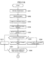
optical microscope 2 for the target cell will be explained with reference to the flowchart shown inFigs. 11A ,11B . - As shown in
Fig. 11A , theimage processing device 10 obtains (S201) the taken image obtained by imaging the maternal blood with theoptical microscope 2, and then performs (S202) the preprocessing such as the median filter on the taken image thus obtained. Further, theimage processing device 10 generates (S203) the binarized image in which the pixels each having a color (e.g., RGB values) within a predetermined range are set to 1 (black pixels) and the other pixels are set to 0 (white pixels) with respect to the taken image on which the preprocessing has been performed. Here, the black pixels in the binarized image represent the candidate area of the nucleus. - The
image processing device 10 connects the pixels adjacent to each other among the black pixels in the binarized image to thereby generate the connected pixel groups, and then performs (S204) the labeling of the connected pixel groups. - The
image processing device 10 selects (S205, the connected pixel group selected here is denoted with Li, and the initial value of i is 1) one of the connected pixel groups thus labeled, and then determines (S206) whether or not the size and the shape of the circumscribed rectangle set with respect to Li satisfy the conditions, which should be satisfied by the candidate of the target cell. In the case in which it is determined in the step S206 that the condition is satisfied (S206:Y), Li is set (S207) as the search target area for the target cell. In the case in which it is determined in the step S206 that the condition is not satisfied (S206:N), Li is not set (S208) as the search target area for the target cell. In the case in which any unselected connected pixel group remains (S209:Y), theimage processing device 10 increments (S210) i, and then returns to S206. In the case in which no unselected connected pixel group remains (S209:N), theimage processing device 10 proceeds to S211. - As shown in
Fig. 11B , theimage processing device 10 selects (S211, the search target area selected here is denoted with Aj, and the initial value of j is 1) one of the search target areas (A1 through Am) set as described above, and further selects (S212) unselected one of the pixels in the circumscribed rectangle of Aj. Then, theimage processing device 10 sets (S213) the rectangular area (the determination target area: size S, an initial value of S is equal to Smin), which has a predetermined size centered on the pixel selected as described above, to the taken image, then normalizes (S214) the direction of the image of the determination target area thus set, and further performs (S215) the image interpolation process in the case in which the distance from the center of the determination target area to the end of the taken image is shorter than the threshold value (i.e., the case in which the determination target area is cut at the end of the taken image). The details of the flow of the image interpolation process will be described later. - After the process described above, the
image processing device 10 calculates (S216) the image feature amount of the image included in the determination target area set as described above, determines (S217) whether or not the target cell is included in the determination target area based on the image feature amount thus calculated and the model parameter of the discriminator for discriminating the image feature amount of the target cell learned in advance, and in the case in which it is determined that the target cell is included (S217:Y), stores (S218) the coordinate range of the taken image corresponding to the determination target area. After S218, or in the case in which it is determined in S217 that the target cell is not included (S217:N), in the case in which any unprocessed pixel remains in the pixels within the circumscribed rectangle of Aj (S219:Y), theimage processing device 10 returns to S212, or in the case in which no unprocessed pixel remains (S219:N), theimage processing device 10 determines (S220) whether or not the size S of the determination target area has reached Smax (>Smin). Here, in the case in which the size S of the determination target area has not yet reached Smax (S220:N), theimage processing device 10 increase (S221) S by ΔS, and then returns to S213, or in the case in which the size S of the determination target area has reached Smax (S220:Y), proceeds to S222. - In the case in which all of the search target areas have not yet been processed (S222:N), the
image processing device 10 increments (S223) j of Aj, then returns to S212. In the case in which all of the search target areas have been processed (S222:Y), theimage processing device 10 displays (S224) the coordinate range of the taken image, which has been determined to include the target cell, and then terminates the process. - Then, the flow of the image interpolation process shown in S215 will be explained with reference to the flowchart shown in
Fig. 12 . - In the case in which the distance (d) from the center of the determination target area to the end of the taken image is shorter than the threshold value (M) (S301:N), the
image processing device 10 expands (S302) the area based on the end of the taken image so that the length of each side becomes M+M pixels, and then sets (S303) the longest part of line segments, which are parallel to the end of the taken image in the binarized image included in the area thus expanded, to the center line. - The
image processing device 10 obtains (S304) the distance L from the center line thus set to the end of the taken image, and then moves a partial area, which is composed of (M-L) pixels perpendicular to the center line, and 2M pixels parallel to the center line, from the end opposed to the end of the taken image with respect to the center line to the position line symmetrical about the center line in the area thus expanded to thereby interpolate (S305) the image in the determination target area. After S305, or in the case in which the distance (d) from the center of the determination target area to the end of the taken image is equal to or longer than the threshold value (S301:Y), theimage processing device 10 returns. - According to the image processing system 1 related to the present embodiment explained hereinabove, since it is arranged that a first refinement is performed on the candidates of the NRBCs (the target cells) included in the maternal blood with the color or the concentration, then the determination target areas are set based on the result of a second refinement further performed on the candidates obtained by the first refinement with the size and the shape of NRBCs, and then whether or not NRBCs are included in the determination target areas is determined by comparing the image feature amount obtained from the determination target area and the criterion obtained by learning based on the positive example and the negative example of NRBCs with each other, it becomes difficult to be affected by the difference between the specimens of the maternal blood and the difference in imaging conditions and so on while easing the burden on the process for detecting NRBCs included in the maternal blood compared to the case of performing the pattern matching on each of the candidates of the cells.
- The invention is not limited to the embodiment described above. For example, although in the embodiment described above, there is described the example of the image processing system 1 in which the taken image of the sample is sequentially input from the
optical microscope 2, it is also possible to arrange that theimage processing device 10 receives a search request for the target cell in the taken image from an information processing device via the communication network, and then returns the search result to the information processing device.
Claims (15)
- An image processing device characterized by comprising:acquisition means adapted to obtain a taken image obtained by imaging a sample including a target cell having a nucleus;first extraction means adapted to extract pixels to be a candidate of the nucleus from pixels included in the taken image based on a first condition determined in advance with respect to at least one of a color and a luminance, which the pixels to be the candidate are required to have;second extraction means adapted to extract a connected pixel group to be a candidate of the target cell from connected pixel groups, each of which is obtained by connecting adjacent ones of the pixels extracted by the first extraction means, based on a second condition determined in advance with respect to a size and a shape, which the connected pixel group to be the candidate is required to have;setting means adapted to set a rectangular area, which has a predetermined size and is centered on a pixel included in the connected pixel group extracted by the second extraction means, to the taken image; anddetermination means adapted to determine whether or not the target cell is included in the rectangular area based on whether or not an image feature amount obtained form the rectangular area set by the setting means satisfies a condition of the image feature amount.
- The image processing device according to Claim 1, characterized in that
the condition of the image feature amount is mechanically learned based on sample images of a positive example and a negative example of the target cell. - The image processing device according to one of Claims 1 and 2, characterized by further comprising:calculation means adapted to calculate the image feature amount obtained from the rectangular area by dividing the rectangular area set by the setting means into predetermined partial areas, calculating a direction of a luminance gradient in each of the pixels in each of the partial areas, calculating a histogram of luminance gradient directions calculated with respect to each of the partial areas, and connecting the histograms of the respective partial areas.
- The image processing device according to any one of Claims 1 through 3, characterized in that
the image feature amount is an HOG feature amount. - The image processing device according to any one of Claims 1 through 4, characterized by further comprising:image feature amount acquisition means adapted to rotate the taken image included in the rectangular area so that a vector connecting a center of the rectangular area set by the setting means and a centroid position of the connected pixel group included in the rectangular area points to a predetermined direction, and then obtain the image feature amount from the taken image rotated,and characterized in that the determination means determines whether or not the target cell is included in the rectangular area based on whether or not the image feature amount obtained by the image feature amount acquisition means satisfies the condition of the image feature amount.
- The image processing device according to any one of Claims 1 through 5, characterized by further comprising:interpolation means adapted to perform interpolation, in a case in which an end of the taken image is included in the rectangular area set by the setting means, by combining an image, which is located on an outer side from a center line set in the connected pixel group included in the rectangular area than an area symmetrical to the end about the center line, to the end side in the image included in the rectangular area.
- The image processing device according to any one of Claims 1 through 6, characterized in that
a coordinate area of the taken image corresponding to the rectangular area determined to include the target cell by the determination means is displayed on a display device. - An image processing method characterized by comprising:an acquisition step adapted to obtain a taken image obtained by imaging a sample including a target cell having a nucleus;a first extraction step adapted to extract pixels to be a candidate of the nucleus from pixels included in the taken image based on a first condition determined in advance with respect to at least one of a color and a luminance, which the pixels to be the candidate are required to have;a second extraction step adapted to extract a connected pixel group to be a candidate of the target cell from connected pixel groups, each of which is obtained by connecting adjacent ones of the pixels extracted in the first extraction step, based on a second condition determined in advance with respect to a size and a shape, which the connected pixel group to be the candidate is required to have;a setting step adapted to set a rectangular area, which has a predetermined size and is centered on a pixel included in the connected pixel group extracted in the second extraction step, to the taken image; anda determination step adapted to determine whether or not the target cell is included in the rectangular area based on whether or not an image feature amount obtained form the rectangular area set in the setting step satisfies a condition of the image feature amount.
- The image processing method according to Claim 8, characterized in that
the condition of the image feature amount is mechanically learned based on sample images of a positive example and a negative example of the target cell. - The image processing method according to one of Claims 8 and 9, characterized by further comprising:a calculation step adapted to calculate the image feature amount obtained from the rectangular area by dividing the rectangular area set in the setting step into predetermined partial areas, calculating a direction of a luminance gradient in each of the pixels in each of the partial areas, calculating a histogram of luminance gradient directions calculated with respect to each of the partial areas, and connecting the histograms of the respective partial areas.
- The image processing method according to any one of Claims 8 through 10, characterized in that
the image feature amount is an HOG feature amount. - An image processing system characterized by comprising:an image processing device, an optical microscope to be connected to the image processing device, and a display device to be connected to the image processing device, and characterized in thatthe image processing device includesacquisition means adapted to obtain a taken image obtained by imaging a sample including a target cell having a nucleus,first extraction means adapted to extract pixels to be a candidate of the nucleus from pixels included in the taken image based on a first condition determined in advance with respect to at least one of a color and a luminance, which the pixels to be the candidate are required to have,second extraction means adapted to extract a connected pixel group to be a candidate of the target cell from connected pixel groups, each of which is obtained by connecting adjacent ones of the pixels extracted by the first extraction means, based on a second condition determined in advance with respect to a size and a shape, which the connected pixel group to be the candidate is required to have,setting means adapted to set a rectangular area, which has a predetermined size and is centered on a pixel included in the connected pixel group extracted by the second extraction means, to the taken image, anddetermination means adapted to determine whether or not the target cell is included in the rectangular area based on whether or not an image feature amount obtained form the rectangular area set by the setting means satisfies a condition of the image feature amount.
- The image processing device according to Claim 12, characterized in that
the condition of the image feature amount is mechanically learned based on sample images of a positive example and a negative example of the target cell. - The image processing device according to one of Claims 12 and 13, characterized by further comprising:calculation means adapted to calculate the image feature amount obtained from the rectangular area by dividing the rectangular area set by the setting means into predetermined partial areas, calculating a direction of a luminance gradient in each of the pixels in each of the partial areas, calculating a histogram of luminance gradient directions calculated with respect to each of the partial areas, and connecting the histograms of the respective partial areas.
- The image processing device according to any one of Claims 12 through 14, characterized in that
the image feature amount is an HOG feature amount.
Applications Claiming Priority (2)
| Application Number | Priority Date | Filing Date | Title |
|---|---|---|---|
| JP2011129350A JP5413408B2 (en) | 2011-06-09 | 2011-06-09 | Image processing apparatus, program, and image processing system |
| PCT/JP2011/075626 WO2012169088A1 (en) | 2011-06-09 | 2011-11-07 | Image processing apparatus, image processing method and image processing system |
Publications (3)
| Publication Number | Publication Date |
|---|---|
| EP2719754A1 true EP2719754A1 (en) | 2014-04-16 |
| EP2719754A4 EP2719754A4 (en) | 2015-01-14 |
| EP2719754B1 EP2719754B1 (en) | 2021-06-23 |
Family
ID=47295683
Family Applications (1)
| Application Number | Title | Priority Date | Filing Date |
|---|---|---|---|
| EP11867361.5A Active EP2719754B1 (en) | 2011-06-09 | 2011-11-07 | Image processing apparatus, image processing method and image processing system |
Country Status (7)
| Country | Link |
|---|---|
| US (1) | US9363486B2 (en) |
| EP (1) | EP2719754B1 (en) |
| JP (1) | JP5413408B2 (en) |
| CN (1) | CN103582697B (en) |
| BR (1) | BR112013030787A8 (en) |
| RU (1) | RU2595495C2 (en) |
| WO (1) | WO2012169088A1 (en) |
Cited By (3)
| Publication number | Priority date | Publication date | Assignee | Title |
|---|---|---|---|---|
| EP3006551A4 (en) * | 2013-05-31 | 2017-02-15 | Fuji Xerox Co., Ltd. | Image processing device, image processing method, program, and storage medium |
| EP3006550A4 (en) * | 2013-05-31 | 2017-03-29 | Fuji Xerox Co., Ltd. | Image processing device, program, storage medium, and image processing method |
| US11493745B2 (en) | 2017-06-26 | 2022-11-08 | Evident Corporation | Cell observation system |
Families Citing this family (21)
| Publication number | Priority date | Publication date | Assignee | Title |
|---|---|---|---|---|
| JP5333635B1 (en) * | 2012-08-23 | 2013-11-06 | 富士ゼロックス株式会社 | Image processing apparatus, program, and image processing system |
| JP6573118B2 (en) * | 2013-07-19 | 2019-09-11 | ソニー株式会社 | Cell evaluation apparatus and method, and program |
| JP6194791B2 (en) | 2013-12-27 | 2017-09-13 | 富士ゼロックス株式会社 | Image processing apparatus and program |
| JP6156137B2 (en) | 2013-12-27 | 2017-07-05 | 富士ゼロックス株式会社 | Image processing apparatus and program |
| JP6277718B2 (en) * | 2013-12-27 | 2018-02-14 | 大日本印刷株式会社 | Medium information registration system, colony detection device, program and hygiene management system |
| JP6197659B2 (en) * | 2014-01-20 | 2017-09-20 | 富士ゼロックス株式会社 | Detection control device, program, and detection system |
| CN106536759A (en) * | 2014-08-05 | 2017-03-22 | 富士胶片株式会社 | How to check fetal chromosomes |
| US10467749B2 (en) | 2016-10-10 | 2019-11-05 | Genemind Biosciences Company Limited | Method and system for processing an image comprising spots in nucleic acid sequencing |
| WO2018068511A1 (en) * | 2016-10-10 | 2018-04-19 | 深圳市瀚海基因生物科技有限公司 | Image processing method and system for gene sequencing |
| WO2019003271A1 (en) * | 2017-06-26 | 2019-01-03 | オリンパス株式会社 | Cell observation system |
| CN107543788A (en) * | 2017-08-15 | 2018-01-05 | 焦作市人民医院 | A kind of urine erythrocyte abnormal rate detection method and system |
| JP6627069B2 (en) * | 2018-06-01 | 2020-01-08 | 株式会社フロンティアファーマ | Image processing method, drug sensitivity test method, and image processing device |
| WO2020026349A1 (en) | 2018-07-31 | 2020-02-06 | オリンパス株式会社 | Diagnostic imaging assistance system and diagnostic imaging assistance device |
| US12008775B2 (en) | 2018-08-22 | 2024-06-11 | Genemind Biosciences Company Limited | Method and device for image registration, and computer program product |
| EP3843034B1 (en) | 2018-08-22 | 2026-03-25 | GeneMind Biosciences Company Limited | Method and device for detecting bright spots on image, and computer program product |
| EP3843033B1 (en) | 2018-08-22 | 2024-05-22 | GeneMind Biosciences Company Limited | Method for constructing sequencing template based on image, and base recognition method and device |
| DE202020101691U1 (en) * | 2019-04-01 | 2020-07-09 | Canon Medical Systems Corporation | Medical image processing device and program |
| JP7434008B2 (en) * | 2019-04-01 | 2024-02-20 | キヤノンメディカルシステムズ株式会社 | Medical image processing equipment and programs |
| CN114600161B (en) * | 2019-09-10 | 2024-12-10 | 株式会社尼康 | Image processing device, image processing method, and program |
| CN118925396B (en) * | 2024-07-18 | 2025-10-10 | 程力汽车集团股份有限公司 | A control method, system and medium for spraying dust suppressant on trains |
| CN120807493B (en) * | 2025-09-05 | 2025-12-30 | 深圳市鑫信腾科技股份有限公司 | Image processing method, apparatus, device, storage medium, and program product |
Family Cites Families (13)
| Publication number | Priority date | Publication date | Assignee | Title |
|---|---|---|---|---|
| JP2903137B2 (en) * | 1992-09-10 | 1999-06-07 | 住友金属工業株式会社 | Nuclear extraction method |
| JPH10185911A (en) | 1996-10-23 | 1998-07-14 | K O Denshi Kogyo Kk | Cell analysis device and method |
| US6169816B1 (en) * | 1997-05-14 | 2001-01-02 | Applied Imaging, Inc. | Identification of objects of interest using multiple illumination schemes and finding overlap of features in corresponding multiple images |
| EP1163502A1 (en) * | 1999-02-18 | 2001-12-19 | Bio-View Ltd | System and method for identifying and analyzing rare cell types in a mixed population of cells |
| JP4346923B2 (en) * | 2003-02-21 | 2009-10-21 | 晴夫 高林 | Target cell automatic search system |
| JP3915033B2 (en) | 2003-05-15 | 2007-05-16 | 株式会社テクノホロン | Measuring method and measuring apparatus using stereo optical system |
| JP5245424B2 (en) | 2008-01-25 | 2013-07-24 | 日本電気株式会社 | Pathological tissue imaging system, pathological tissue imaging method, and pathological tissue imaging program |
| JP5380026B2 (en) * | 2008-09-24 | 2014-01-08 | シスメックス株式会社 | Sample imaging device |
| RU2385494C1 (en) * | 2008-10-22 | 2010-03-27 | Государственное образовательное учреждение высшего профессионального образования Московский инженерно-физический институт (государственный университет) | Method for recognition of cell texture image |
| EP3065105B1 (en) | 2009-06-12 | 2020-04-29 | Nikon Corporation | Technique for determining the state of a cell aggregation, image processing program and image processing device using the technique, and method for producing a cell aggregation |
| WO2010146802A1 (en) | 2009-06-19 | 2010-12-23 | 株式会社ニコン | State determination method for cell cluster, image processing program and imaging processing device using said method, and method for producing cell cluster |
| WO2011013319A1 (en) | 2009-07-31 | 2011-02-03 | 株式会社ニコン | Technique for determining maturity of cell mass, and image processing program and image processing device which use the technique, and method for producing cell mass |
| WO2011016189A1 (en) | 2009-08-07 | 2011-02-10 | 株式会社ニコン | Technique for classifying cells, image processing program and image processing device using the technique, and method for producing cell mass |
-
2011
- 2011-06-09 JP JP2011129350A patent/JP5413408B2/en active Active
- 2011-11-07 RU RU2013153508/08A patent/RU2595495C2/en active
- 2011-11-07 EP EP11867361.5A patent/EP2719754B1/en active Active
- 2011-11-07 WO PCT/JP2011/075626 patent/WO2012169088A1/en not_active Ceased
- 2011-11-07 BR BR112013030787A patent/BR112013030787A8/en not_active IP Right Cessation
- 2011-11-07 CN CN201180071407.8A patent/CN103582697B/en active Active
-
2013
- 2013-12-05 US US14/097,500 patent/US9363486B2/en active Active
Cited By (4)
| Publication number | Priority date | Publication date | Assignee | Title |
|---|---|---|---|---|
| EP3006551A4 (en) * | 2013-05-31 | 2017-02-15 | Fuji Xerox Co., Ltd. | Image processing device, image processing method, program, and storage medium |
| EP3006550A4 (en) * | 2013-05-31 | 2017-03-29 | Fuji Xerox Co., Ltd. | Image processing device, program, storage medium, and image processing method |
| US9858662B2 (en) | 2013-05-31 | 2018-01-02 | Fuji Xerox Co., Ltd. | Image processing device, computer storage medium, and method for detecting and displaying nucleated target cells |
| US11493745B2 (en) | 2017-06-26 | 2022-11-08 | Evident Corporation | Cell observation system |
Also Published As
| Publication number | Publication date |
|---|---|
| BR112013030787A2 (en) | 2016-09-06 |
| EP2719754A4 (en) | 2015-01-14 |
| US9363486B2 (en) | 2016-06-07 |
| US20140092228A1 (en) | 2014-04-03 |
| JP5413408B2 (en) | 2014-02-12 |
| CN103582697A (en) | 2014-02-12 |
| RU2595495C2 (en) | 2016-08-27 |
| JP2012254042A (en) | 2012-12-27 |
| CN103582697B (en) | 2017-04-05 |
| RU2013153508A (en) | 2015-07-20 |
| EP2719754B1 (en) | 2021-06-23 |
| WO2012169088A1 (en) | 2012-12-13 |
| BR112013030787A8 (en) | 2017-12-19 |
Similar Documents
| Publication | Publication Date | Title |
|---|---|---|
| EP2719754B1 (en) | Image processing apparatus, image processing method and image processing system | |
| JP5333570B2 (en) | Image processing apparatus, program, and image processing system | |
| US9934571B2 (en) | Image processing device, program, image processing method, computer-readable medium, and image processing system | |
| US9704017B2 (en) | Image processing device, program, image processing method, computer-readable medium, and image processing system | |
| US9684958B2 (en) | Image processing device, program, image processing method, computer-readable medium, and image processing system | |
| US10169861B2 (en) | Image processing apparatus, non-transitory computer readable medium, and image processing method | |
| EP3124967B1 (en) | Image-processing device and image-processing program | |
| JP5413501B1 (en) | Image processing apparatus, image processing system, and program | |
| EP3895122B1 (en) | Systems and methods for automated cell segmentation and labeling in immunofluorescence microscopy | |
| EP3006551B1 (en) | Image processing device, image processing method, program, and storage medium | |
| CN110956180A (en) | Counterweight weight detection method and system, acquisition method and system, and crane | |
| JP2009236728A (en) | Image analyzer, its method, program, and recording medium | |
| JP5907125B2 (en) | Image processing apparatus, program, and image processing system | |
| CN116091382A (en) | Sperm tail morphology recognition method, sperm morphology analyzer and storage medium | |
| JP5861678B2 (en) | Image processing apparatus, program, and image processing system | |
| AU2021103689A4 (en) | A Method for Automatic Detection of Infected Erythrocytes | |
| CN120164215B (en) | Cervical cell identification method and system | |
| CN113066121A (en) | Image analysis system and method for identifying repeat cells | |
| CN119494839B (en) | A battery pole piece detection method and system based on image recognition | |
| CN119741553A (en) | Image processing method, device, electronic equipment and storage medium |
Legal Events
| Date | Code | Title | Description |
|---|---|---|---|
| PUAI | Public reference made under article 153(3) epc to a published international application that has entered the european phase |
Free format text: ORIGINAL CODE: 0009012 |
|
| 17P | Request for examination filed |
Effective date: 20140107 |
|
| AK | Designated contracting states |
Kind code of ref document: A1 Designated state(s): AL AT BE BG CH CY CZ DE DK EE ES FI FR GB GR HR HU IE IS IT LI LT LU LV MC MK MT NL NO PL PT RO RS SE SI SK SM TR |
|
| DAX | Request for extension of the european patent (deleted) | ||
| A4 | Supplementary search report drawn up and despatched |
Effective date: 20141215 |
|
| RIC1 | Information provided on ipc code assigned before grant |
Ipc: C12Q 1/02 20060101ALI20141209BHEP Ipc: C12M 1/34 20060101AFI20141209BHEP Ipc: G06T 7/00 20060101ALN20141209BHEP Ipc: C12M 1/00 20060101ALI20141209BHEP Ipc: H04N 7/18 20060101ALN20141209BHEP Ipc: G06K 9/00 20060101ALN20141209BHEP Ipc: G01N 21/27 20060101ALI20141209BHEP |
|
| STAA | Information on the status of an ep patent application or granted ep patent |
Free format text: STATUS: EXAMINATION IS IN PROGRESS |
|
| 17Q | First examination report despatched |
Effective date: 20170331 |
|
| RAP1 | Party data changed (applicant data changed or rights of an application transferred) |
Owner name: FUJIFILM CORPORATION |
|
| GRAP | Despatch of communication of intention to grant a patent |
Free format text: ORIGINAL CODE: EPIDOSNIGR1 |
|
| STAA | Information on the status of an ep patent application or granted ep patent |
Free format text: STATUS: GRANT OF PATENT IS INTENDED |
|
| RAP3 | Party data changed (applicant data changed or rights of an application transferred) |
Owner name: FUJIFILM CORPORATION |
|
| RIC1 | Information provided on ipc code assigned before grant |
Ipc: C12M 1/34 20060101AFI20210311BHEP Ipc: C12M 1/00 20060101ALI20210311BHEP Ipc: C12Q 1/02 20060101ALI20210311BHEP Ipc: G01N 21/27 20060101ALI20210311BHEP Ipc: G06K 9/00 20060101ALN20210311BHEP Ipc: G06T 7/00 20170101ALN20210311BHEP Ipc: H04N 7/18 20060101ALN20210311BHEP |
|
| INTG | Intention to grant announced |
Effective date: 20210329 |
|
| GRAS | Grant fee paid |
Free format text: ORIGINAL CODE: EPIDOSNIGR3 |
|
| GRAA | (expected) grant |
Free format text: ORIGINAL CODE: 0009210 |
|
| STAA | Information on the status of an ep patent application or granted ep patent |
Free format text: STATUS: THE PATENT HAS BEEN GRANTED |
|
| AK | Designated contracting states |
Kind code of ref document: B1 Designated state(s): AL AT BE BG CH CY CZ DE DK EE ES FI FR GB GR HR HU IE IS IT LI LT LU LV MC MK MT NL NO PL PT RO RS SE SI SK SM TR |
|
| REG | Reference to a national code |
Ref country code: GB Ref legal event code: FG4D |
|
| REG | Reference to a national code |
Ref country code: CH Ref legal event code: EP |
|
| REG | Reference to a national code |
Ref country code: DE Ref legal event code: R096 Ref document number: 602011071247 Country of ref document: DE Ref country code: AT Ref legal event code: REF Ref document number: 1404333 Country of ref document: AT Kind code of ref document: T Effective date: 20210715 |
|
| REG | Reference to a national code |
Ref country code: IE Ref legal event code: FG4D |
|
| REG | Reference to a national code |
Ref country code: LT Ref legal event code: MG9D |
|
| PG25 | Lapsed in a contracting state [announced via postgrant information from national office to epo] |
Ref country code: BG Free format text: LAPSE BECAUSE OF FAILURE TO SUBMIT A TRANSLATION OF THE DESCRIPTION OR TO PAY THE FEE WITHIN THE PRESCRIBED TIME-LIMIT Effective date: 20210923 Ref country code: HR Free format text: LAPSE BECAUSE OF FAILURE TO SUBMIT A TRANSLATION OF THE DESCRIPTION OR TO PAY THE FEE WITHIN THE PRESCRIBED TIME-LIMIT Effective date: 20210623 Ref country code: LT Free format text: LAPSE BECAUSE OF FAILURE TO SUBMIT A TRANSLATION OF THE DESCRIPTION OR TO PAY THE FEE WITHIN THE PRESCRIBED TIME-LIMIT Effective date: 20210623 Ref country code: FI Free format text: LAPSE BECAUSE OF FAILURE TO SUBMIT A TRANSLATION OF THE DESCRIPTION OR TO PAY THE FEE WITHIN THE PRESCRIBED TIME-LIMIT Effective date: 20210623 |
|
| REG | Reference to a national code |
Ref country code: AT Ref legal event code: MK05 Ref document number: 1404333 Country of ref document: AT Kind code of ref document: T Effective date: 20210623 |
|
| PG25 | Lapsed in a contracting state [announced via postgrant information from national office to epo] |
Ref country code: NO Free format text: LAPSE BECAUSE OF FAILURE TO SUBMIT A TRANSLATION OF THE DESCRIPTION OR TO PAY THE FEE WITHIN THE PRESCRIBED TIME-LIMIT Effective date: 20210923 Ref country code: LV Free format text: LAPSE BECAUSE OF FAILURE TO SUBMIT A TRANSLATION OF THE DESCRIPTION OR TO PAY THE FEE WITHIN THE PRESCRIBED TIME-LIMIT Effective date: 20210623 Ref country code: GR Free format text: LAPSE BECAUSE OF FAILURE TO SUBMIT A TRANSLATION OF THE DESCRIPTION OR TO PAY THE FEE WITHIN THE PRESCRIBED TIME-LIMIT Effective date: 20210924 Ref country code: SE Free format text: LAPSE BECAUSE OF FAILURE TO SUBMIT A TRANSLATION OF THE DESCRIPTION OR TO PAY THE FEE WITHIN THE PRESCRIBED TIME-LIMIT Effective date: 20210623 Ref country code: RS Free format text: LAPSE BECAUSE OF FAILURE TO SUBMIT A TRANSLATION OF THE DESCRIPTION OR TO PAY THE FEE WITHIN THE PRESCRIBED TIME-LIMIT Effective date: 20210623 |
|
| REG | Reference to a national code |
Ref country code: NL Ref legal event code: MP Effective date: 20210623 |
|
| PG25 | Lapsed in a contracting state [announced via postgrant information from national office to epo] |
Ref country code: AT Free format text: LAPSE BECAUSE OF FAILURE TO SUBMIT A TRANSLATION OF THE DESCRIPTION OR TO PAY THE FEE WITHIN THE PRESCRIBED TIME-LIMIT Effective date: 20210623 Ref country code: NL Free format text: LAPSE BECAUSE OF FAILURE TO SUBMIT A TRANSLATION OF THE DESCRIPTION OR TO PAY THE FEE WITHIN THE PRESCRIBED TIME-LIMIT Effective date: 20210623 Ref country code: PT Free format text: LAPSE BECAUSE OF FAILURE TO SUBMIT A TRANSLATION OF THE DESCRIPTION OR TO PAY THE FEE WITHIN THE PRESCRIBED TIME-LIMIT Effective date: 20211025 Ref country code: RO Free format text: LAPSE BECAUSE OF FAILURE TO SUBMIT A TRANSLATION OF THE DESCRIPTION OR TO PAY THE FEE WITHIN THE PRESCRIBED TIME-LIMIT Effective date: 20210623 Ref country code: ES Free format text: LAPSE BECAUSE OF FAILURE TO SUBMIT A TRANSLATION OF THE DESCRIPTION OR TO PAY THE FEE WITHIN THE PRESCRIBED TIME-LIMIT Effective date: 20210623 Ref country code: CZ Free format text: LAPSE BECAUSE OF FAILURE TO SUBMIT A TRANSLATION OF THE DESCRIPTION OR TO PAY THE FEE WITHIN THE PRESCRIBED TIME-LIMIT Effective date: 20210623 Ref country code: EE Free format text: LAPSE BECAUSE OF FAILURE TO SUBMIT A TRANSLATION OF THE DESCRIPTION OR TO PAY THE FEE WITHIN THE PRESCRIBED TIME-LIMIT Effective date: 20210623 Ref country code: SM Free format text: LAPSE BECAUSE OF FAILURE TO SUBMIT A TRANSLATION OF THE DESCRIPTION OR TO PAY THE FEE WITHIN THE PRESCRIBED TIME-LIMIT Effective date: 20210623 Ref country code: SK Free format text: LAPSE BECAUSE OF FAILURE TO SUBMIT A TRANSLATION OF THE DESCRIPTION OR TO PAY THE FEE WITHIN THE PRESCRIBED TIME-LIMIT Effective date: 20210623 |
|
| PG25 | Lapsed in a contracting state [announced via postgrant information from national office to epo] |
Ref country code: PL Free format text: LAPSE BECAUSE OF FAILURE TO SUBMIT A TRANSLATION OF THE DESCRIPTION OR TO PAY THE FEE WITHIN THE PRESCRIBED TIME-LIMIT Effective date: 20210623 |
|
| REG | Reference to a national code |
Ref country code: DE Ref legal event code: R097 Ref document number: 602011071247 Country of ref document: DE |
|
| PG25 | Lapsed in a contracting state [announced via postgrant information from national office to epo] |
Ref country code: DK Free format text: LAPSE BECAUSE OF FAILURE TO SUBMIT A TRANSLATION OF THE DESCRIPTION OR TO PAY THE FEE WITHIN THE PRESCRIBED TIME-LIMIT Effective date: 20210623 |
|
| PLBE | No opposition filed within time limit |
Free format text: ORIGINAL CODE: 0009261 |
|
| STAA | Information on the status of an ep patent application or granted ep patent |
Free format text: STATUS: NO OPPOSITION FILED WITHIN TIME LIMIT |
|
| 26N | No opposition filed |
Effective date: 20220324 |
|
| PG25 | Lapsed in a contracting state [announced via postgrant information from national office to epo] |
Ref country code: AL Free format text: LAPSE BECAUSE OF FAILURE TO SUBMIT A TRANSLATION OF THE DESCRIPTION OR TO PAY THE FEE WITHIN THE PRESCRIBED TIME-LIMIT Effective date: 20210623 |
|
| PG25 | Lapsed in a contracting state [announced via postgrant information from national office to epo] |
Ref country code: MC Free format text: LAPSE BECAUSE OF FAILURE TO SUBMIT A TRANSLATION OF THE DESCRIPTION OR TO PAY THE FEE WITHIN THE PRESCRIBED TIME-LIMIT Effective date: 20210623 |
|
| GBPC | Gb: european patent ceased through non-payment of renewal fee |
Effective date: 20211107 |
|
| PG25 | Lapsed in a contracting state [announced via postgrant information from national office to epo] |
Ref country code: LU Free format text: LAPSE BECAUSE OF NON-PAYMENT OF DUE FEES Effective date: 20211107 Ref country code: IT Free format text: LAPSE BECAUSE OF FAILURE TO SUBMIT A TRANSLATION OF THE DESCRIPTION OR TO PAY THE FEE WITHIN THE PRESCRIBED TIME-LIMIT Effective date: 20210623 Ref country code: BE Free format text: LAPSE BECAUSE OF NON-PAYMENT OF DUE FEES Effective date: 20211130 |
|
| REG | Reference to a national code |
Ref country code: BE Ref legal event code: MM Effective date: 20211130 |
|
| PG25 | Lapsed in a contracting state [announced via postgrant information from national office to epo] |
Ref country code: IE Free format text: LAPSE BECAUSE OF NON-PAYMENT OF DUE FEES Effective date: 20211107 Ref country code: GB Free format text: LAPSE BECAUSE OF NON-PAYMENT OF DUE FEES Effective date: 20211107 |
|
| PG25 | Lapsed in a contracting state [announced via postgrant information from national office to epo] |
Ref country code: FR Free format text: LAPSE BECAUSE OF NON-PAYMENT OF DUE FEES Effective date: 20211130 |
|
| PG25 | Lapsed in a contracting state [announced via postgrant information from national office to epo] |
Ref country code: HU Free format text: LAPSE BECAUSE OF FAILURE TO SUBMIT A TRANSLATION OF THE DESCRIPTION OR TO PAY THE FEE WITHIN THE PRESCRIBED TIME-LIMIT; INVALID AB INITIO Effective date: 20111107 Ref country code: CY Free format text: LAPSE BECAUSE OF FAILURE TO SUBMIT A TRANSLATION OF THE DESCRIPTION OR TO PAY THE FEE WITHIN THE PRESCRIBED TIME-LIMIT Effective date: 20210623 |
|
| P01 | Opt-out of the competence of the unified patent court (upc) registered |
Effective date: 20230515 |
|
| PG25 | Lapsed in a contracting state [announced via postgrant information from national office to epo] |
Ref country code: MK Free format text: LAPSE BECAUSE OF FAILURE TO SUBMIT A TRANSLATION OF THE DESCRIPTION OR TO PAY THE FEE WITHIN THE PRESCRIBED TIME-LIMIT Effective date: 20210623 |
|
| PG25 | Lapsed in a contracting state [announced via postgrant information from national office to epo] |
Ref country code: TR Free format text: LAPSE BECAUSE OF FAILURE TO SUBMIT A TRANSLATION OF THE DESCRIPTION OR TO PAY THE FEE WITHIN THE PRESCRIBED TIME-LIMIT Effective date: 20210623 |
|
| PG25 | Lapsed in a contracting state [announced via postgrant information from national office to epo] |
Ref country code: MT Free format text: LAPSE BECAUSE OF FAILURE TO SUBMIT A TRANSLATION OF THE DESCRIPTION OR TO PAY THE FEE WITHIN THE PRESCRIBED TIME-LIMIT Effective date: 20210623 |
|
| REG | Reference to a national code |
Ref country code: CH Ref legal event code: U11 Free format text: ST27 STATUS EVENT CODE: U-0-0-U10-U11 (AS PROVIDED BY THE NATIONAL OFFICE) Effective date: 20251201 |
|
| PGFP | Annual fee paid to national office [announced via postgrant information from national office to epo] |
Ref country code: DE Payment date: 20250930 Year of fee payment: 15 |
|
| PGFP | Annual fee paid to national office [announced via postgrant information from national office to epo] |
Ref country code: CH Payment date: 20251201 Year of fee payment: 15 |