EP2719403B1 - Pompe sanguine centrifuge - Google Patents
Pompe sanguine centrifuge Download PDFInfo
- Publication number
- EP2719403B1 EP2719403B1 EP12188316.9A EP12188316A EP2719403B1 EP 2719403 B1 EP2719403 B1 EP 2719403B1 EP 12188316 A EP12188316 A EP 12188316A EP 2719403 B1 EP2719403 B1 EP 2719403B1
- Authority
- EP
- European Patent Office
- Prior art keywords
- impeller
- blades
- disc
- blood pump
- pump according
- Prior art date
- Legal status (The legal status is an assumption and is not a legal conclusion. Google has not performed a legal analysis and makes no representation as to the accuracy of the status listed.)
- Active
Links
- 239000008280 blood Substances 0.000 title claims description 128
- 210000004369 blood Anatomy 0.000 title claims description 128
- 230000005291 magnetic effect Effects 0.000 claims description 52
- 230000017531 blood circulation Effects 0.000 claims description 49
- 239000000919 ceramic Substances 0.000 claims description 25
- 230000005294 ferromagnetic effect Effects 0.000 claims description 9
- 239000003302 ferromagnetic material Substances 0.000 claims description 7
- 238000002347 injection Methods 0.000 claims description 6
- 239000007924 injection Substances 0.000 claims description 6
- 230000000694 effects Effects 0.000 description 11
- 239000002184 metal Substances 0.000 description 7
- 229910052751 metal Inorganic materials 0.000 description 7
- 239000000696 magnetic material Substances 0.000 description 6
- 229920000642 polymer Polymers 0.000 description 5
- 238000000429 assembly Methods 0.000 description 4
- 230000000712 assembly Effects 0.000 description 4
- 230000007774 longterm Effects 0.000 description 4
- 230000010349 pulsation Effects 0.000 description 4
- 230000007797 corrosion Effects 0.000 description 3
- 238000005260 corrosion Methods 0.000 description 3
- 210000005240 left ventricle Anatomy 0.000 description 3
- 239000000463 material Substances 0.000 description 3
- 239000011159 matrix material Substances 0.000 description 3
- RTAQQCXQSZGOHL-UHFFFAOYSA-N Titanium Chemical compound [Ti] RTAQQCXQSZGOHL-UHFFFAOYSA-N 0.000 description 2
- 210000000709 aorta Anatomy 0.000 description 2
- 230000000903 blocking effect Effects 0.000 description 2
- 239000000306 component Substances 0.000 description 2
- 239000002861 polymer material Substances 0.000 description 2
- 239000010970 precious metal Substances 0.000 description 2
- 230000001846 repelling effect Effects 0.000 description 2
- 230000003068 static effect Effects 0.000 description 2
- 239000010936 titanium Substances 0.000 description 2
- 229910052719 titanium Inorganic materials 0.000 description 2
- 208000007536 Thrombosis Diseases 0.000 description 1
- 230000002411 adverse Effects 0.000 description 1
- 210000002376 aorta thoracic Anatomy 0.000 description 1
- 230000001174 ascending effect Effects 0.000 description 1
- 239000012503 blood component Substances 0.000 description 1
- 230000015556 catabolic process Effects 0.000 description 1
- 239000011248 coating agent Substances 0.000 description 1
- 238000000576 coating method Methods 0.000 description 1
- 238000004891 communication Methods 0.000 description 1
- 238000010276 construction Methods 0.000 description 1
- 230000001419 dependent effect Effects 0.000 description 1
- 238000011161 development Methods 0.000 description 1
- 230000018109 developmental process Effects 0.000 description 1
- 238000005538 encapsulation Methods 0.000 description 1
- 238000005265 energy consumption Methods 0.000 description 1
- 239000012530 fluid Substances 0.000 description 1
- 238000001465 metallisation Methods 0.000 description 1
- 238000000034 method Methods 0.000 description 1
- 238000000465 moulding Methods 0.000 description 1
- 239000002245 particle Substances 0.000 description 1
- 230000000149 penetrating effect Effects 0.000 description 1
- 238000004904 shortening Methods 0.000 description 1
- 238000005406 washing Methods 0.000 description 1
Images


Classifications
-
- A—HUMAN NECESSITIES
- A61—MEDICAL OR VETERINARY SCIENCE; HYGIENE
- A61M—DEVICES FOR INTRODUCING MEDIA INTO, OR ONTO, THE BODY; DEVICES FOR TRANSDUCING BODY MEDIA OR FOR TAKING MEDIA FROM THE BODY; DEVICES FOR PRODUCING OR ENDING SLEEP OR STUPOR
- A61M60/00—Blood pumps; Devices for mechanical circulatory actuation; Balloon pumps for circulatory assistance
- A61M60/10—Location thereof with respect to the patient's body
- A61M60/122—Implantable pumps or pumping devices, i.e. the blood being pumped inside the patient's body
- A61M60/126—Implantable pumps or pumping devices, i.e. the blood being pumped inside the patient's body implantable via, into, inside, in line, branching on, or around a blood vessel
- A61M60/148—Implantable pumps or pumping devices, i.e. the blood being pumped inside the patient's body implantable via, into, inside, in line, branching on, or around a blood vessel in line with a blood vessel using resection or like techniques, e.g. permanent endovascular heart assist devices
-
- A—HUMAN NECESSITIES
- A61—MEDICAL OR VETERINARY SCIENCE; HYGIENE
- A61M—DEVICES FOR INTRODUCING MEDIA INTO, OR ONTO, THE BODY; DEVICES FOR TRANSDUCING BODY MEDIA OR FOR TAKING MEDIA FROM THE BODY; DEVICES FOR PRODUCING OR ENDING SLEEP OR STUPOR
- A61M60/00—Blood pumps; Devices for mechanical circulatory actuation; Balloon pumps for circulatory assistance
- A61M60/20—Type thereof
- A61M60/205—Non-positive displacement blood pumps
-
- F—MECHANICAL ENGINEERING; LIGHTING; HEATING; WEAPONS; BLASTING
- F04—POSITIVE - DISPLACEMENT MACHINES FOR LIQUIDS; PUMPS FOR LIQUIDS OR ELASTIC FLUIDS
- F04D—NON-POSITIVE-DISPLACEMENT PUMPS
- F04D13/00—Pumping installations or systems
- F04D13/02—Units comprising pumps and their driving means
- F04D13/021—Units comprising pumps and their driving means containing a coupling
- F04D13/024—Units comprising pumps and their driving means containing a coupling a magnetic coupling
- F04D13/027—Details of the magnetic circuit
-
- A—HUMAN NECESSITIES
- A61—MEDICAL OR VETERINARY SCIENCE; HYGIENE
- A61M—DEVICES FOR INTRODUCING MEDIA INTO, OR ONTO, THE BODY; DEVICES FOR TRANSDUCING BODY MEDIA OR FOR TAKING MEDIA FROM THE BODY; DEVICES FOR PRODUCING OR ENDING SLEEP OR STUPOR
- A61M60/00—Blood pumps; Devices for mechanical circulatory actuation; Balloon pumps for circulatory assistance
- A61M60/10—Location thereof with respect to the patient's body
- A61M60/122—Implantable pumps or pumping devices, i.e. the blood being pumped inside the patient's body
- A61M60/165—Implantable pumps or pumping devices, i.e. the blood being pumped inside the patient's body implantable in, on, or around the heart
- A61M60/178—Implantable pumps or pumping devices, i.e. the blood being pumped inside the patient's body implantable in, on, or around the heart drawing blood from a ventricle and returning the blood to the arterial system via a cannula external to the ventricle, e.g. left or right ventricular assist devices
-
- A—HUMAN NECESSITIES
- A61—MEDICAL OR VETERINARY SCIENCE; HYGIENE
- A61M—DEVICES FOR INTRODUCING MEDIA INTO, OR ONTO, THE BODY; DEVICES FOR TRANSDUCING BODY MEDIA OR FOR TAKING MEDIA FROM THE BODY; DEVICES FOR PRODUCING OR ENDING SLEEP OR STUPOR
- A61M60/00—Blood pumps; Devices for mechanical circulatory actuation; Balloon pumps for circulatory assistance
- A61M60/20—Type thereof
- A61M60/205—Non-positive displacement blood pumps
- A61M60/216—Non-positive displacement blood pumps including a rotating member acting on the blood, e.g. impeller
- A61M60/226—Non-positive displacement blood pumps including a rotating member acting on the blood, e.g. impeller the blood flow through the rotating member having mainly radial components
- A61M60/232—Centrifugal pumps
-
- A—HUMAN NECESSITIES
- A61—MEDICAL OR VETERINARY SCIENCE; HYGIENE
- A61M—DEVICES FOR INTRODUCING MEDIA INTO, OR ONTO, THE BODY; DEVICES FOR TRANSDUCING BODY MEDIA OR FOR TAKING MEDIA FROM THE BODY; DEVICES FOR PRODUCING OR ENDING SLEEP OR STUPOR
- A61M60/00—Blood pumps; Devices for mechanical circulatory actuation; Balloon pumps for circulatory assistance
- A61M60/40—Details relating to driving
- A61M60/403—Details relating to driving for non-positive displacement blood pumps
- A61M60/419—Details relating to driving for non-positive displacement blood pumps the force acting on the blood contacting member being permanent magnetic, e.g. from a rotating magnetic coupling between driving and driven magnets
-
- A—HUMAN NECESSITIES
- A61—MEDICAL OR VETERINARY SCIENCE; HYGIENE
- A61M—DEVICES FOR INTRODUCING MEDIA INTO, OR ONTO, THE BODY; DEVICES FOR TRANSDUCING BODY MEDIA OR FOR TAKING MEDIA FROM THE BODY; DEVICES FOR PRODUCING OR ENDING SLEEP OR STUPOR
- A61M60/00—Blood pumps; Devices for mechanical circulatory actuation; Balloon pumps for circulatory assistance
- A61M60/40—Details relating to driving
- A61M60/403—Details relating to driving for non-positive displacement blood pumps
- A61M60/422—Details relating to driving for non-positive displacement blood pumps the force acting on the blood contacting member being electromagnetic, e.g. using canned motor pumps
-
- A—HUMAN NECESSITIES
- A61—MEDICAL OR VETERINARY SCIENCE; HYGIENE
- A61M—DEVICES FOR INTRODUCING MEDIA INTO, OR ONTO, THE BODY; DEVICES FOR TRANSDUCING BODY MEDIA OR FOR TAKING MEDIA FROM THE BODY; DEVICES FOR PRODUCING OR ENDING SLEEP OR STUPOR
- A61M60/00—Blood pumps; Devices for mechanical circulatory actuation; Balloon pumps for circulatory assistance
- A61M60/50—Details relating to control
- A61M60/585—User interfaces
-
- A—HUMAN NECESSITIES
- A61—MEDICAL OR VETERINARY SCIENCE; HYGIENE
- A61M—DEVICES FOR INTRODUCING MEDIA INTO, OR ONTO, THE BODY; DEVICES FOR TRANSDUCING BODY MEDIA OR FOR TAKING MEDIA FROM THE BODY; DEVICES FOR PRODUCING OR ENDING SLEEP OR STUPOR
- A61M60/00—Blood pumps; Devices for mechanical circulatory actuation; Balloon pumps for circulatory assistance
- A61M60/80—Constructional details other than related to driving
- A61M60/802—Constructional details other than related to driving of non-positive displacement blood pumps
- A61M60/804—Impellers
- A61M60/806—Vanes or blades
-
- A—HUMAN NECESSITIES
- A61—MEDICAL OR VETERINARY SCIENCE; HYGIENE
- A61M—DEVICES FOR INTRODUCING MEDIA INTO, OR ONTO, THE BODY; DEVICES FOR TRANSDUCING BODY MEDIA OR FOR TAKING MEDIA FROM THE BODY; DEVICES FOR PRODUCING OR ENDING SLEEP OR STUPOR
- A61M60/00—Blood pumps; Devices for mechanical circulatory actuation; Balloon pumps for circulatory assistance
- A61M60/80—Constructional details other than related to driving
- A61M60/802—Constructional details other than related to driving of non-positive displacement blood pumps
- A61M60/818—Bearings
- A61M60/824—Hydrodynamic or fluid film bearings
-
- A—HUMAN NECESSITIES
- A61—MEDICAL OR VETERINARY SCIENCE; HYGIENE
- A61M—DEVICES FOR INTRODUCING MEDIA INTO, OR ONTO, THE BODY; DEVICES FOR TRANSDUCING BODY MEDIA OR FOR TAKING MEDIA FROM THE BODY; DEVICES FOR PRODUCING OR ENDING SLEEP OR STUPOR
- A61M60/00—Blood pumps; Devices for mechanical circulatory actuation; Balloon pumps for circulatory assistance
- A61M60/80—Constructional details other than related to driving
- A61M60/855—Constructional details other than related to driving of implantable pumps or pumping devices
- A61M60/871—Energy supply devices; Converters therefor
- A61M60/873—Energy supply devices; Converters therefor specially adapted for wireless or transcutaneous energy transfer [TET], e.g. inductive charging
-
- F—MECHANICAL ENGINEERING; LIGHTING; HEATING; WEAPONS; BLASTING
- F04—POSITIVE - DISPLACEMENT MACHINES FOR LIQUIDS; PUMPS FOR LIQUIDS OR ELASTIC FLUIDS
- F04D—NON-POSITIVE-DISPLACEMENT PUMPS
- F04D1/00—Radial-flow pumps, e.g. centrifugal pumps; Helico-centrifugal pumps
-
- F—MECHANICAL ENGINEERING; LIGHTING; HEATING; WEAPONS; BLASTING
- F04—POSITIVE - DISPLACEMENT MACHINES FOR LIQUIDS; PUMPS FOR LIQUIDS OR ELASTIC FLUIDS
- F04D—NON-POSITIVE-DISPLACEMENT PUMPS
- F04D13/00—Pumping installations or systems
- F04D13/02—Units comprising pumps and their driving means
- F04D13/06—Units comprising pumps and their driving means the pump being electrically driven
-
- F—MECHANICAL ENGINEERING; LIGHTING; HEATING; WEAPONS; BLASTING
- F04—POSITIVE - DISPLACEMENT MACHINES FOR LIQUIDS; PUMPS FOR LIQUIDS OR ELASTIC FLUIDS
- F04D—NON-POSITIVE-DISPLACEMENT PUMPS
- F04D29/00—Details, component parts, or accessories
- F04D29/18—Rotors
- F04D29/186—Shaftless rotors
-
- F—MECHANICAL ENGINEERING; LIGHTING; HEATING; WEAPONS; BLASTING
- F04—POSITIVE - DISPLACEMENT MACHINES FOR LIQUIDS; PUMPS FOR LIQUIDS OR ELASTIC FLUIDS
- F04D—NON-POSITIVE-DISPLACEMENT PUMPS
- F04D29/00—Details, component parts, or accessories
- F04D29/40—Casings; Connections of working fluid
- F04D29/42—Casings; Connections of working fluid for radial or helico-centrifugal pumps
- F04D29/426—Casings; Connections of working fluid for radial or helico-centrifugal pumps especially adapted for liquid pumps
-
- F—MECHANICAL ENGINEERING; LIGHTING; HEATING; WEAPONS; BLASTING
- F04—POSITIVE - DISPLACEMENT MACHINES FOR LIQUIDS; PUMPS FOR LIQUIDS OR ELASTIC FLUIDS
- F04D—NON-POSITIVE-DISPLACEMENT PUMPS
- F04D7/00—Pumps adapted for handling specific fluids, e.g. by selection of specific materials for pumps or pump parts
- F04D7/02—Pumps adapted for handling specific fluids, e.g. by selection of specific materials for pumps or pump parts of centrifugal type
- F04D7/04—Pumps adapted for handling specific fluids, e.g. by selection of specific materials for pumps or pump parts of centrifugal type the fluids being viscous or non-homogenous
-
- H—ELECTRICITY
- H02—GENERATION; CONVERSION OR DISTRIBUTION OF ELECTRIC POWER
- H02K—DYNAMO-ELECTRIC MACHINES
- H02K1/00—Details of the magnetic circuit
- H02K1/06—Details of the magnetic circuit characterised by the shape, form or construction
- H02K1/22—Rotating parts of the magnetic circuit
- H02K1/27—Rotor cores with permanent magnets
- H02K1/2793—Rotors axially facing stators
- H02K1/2795—Rotors axially facing stators the rotor consisting of two or more circumferentially positioned magnets
-
- H—ELECTRICITY
- H02—GENERATION; CONVERSION OR DISTRIBUTION OF ELECTRIC POWER
- H02K—DYNAMO-ELECTRIC MACHINES
- H02K3/00—Details of windings
- H02K3/46—Fastening of windings on the stator or rotor structure
- H02K3/47—Air-gap windings, i.e. iron-free windings
Definitions
- the invention relates to a centrifugal blood pump, i.e. a pump having a rotating impeller by means of which blood is transported in an outward radial direction.
- the blood pump is particularly suitable for long-term blood conveyance but may likewise be used only temporarily and offers a delivery rate of at least 4 and up to 10 liters per minute.
- Centrifugal blood pumps for long-term use are described e.g. in US 6,623,475 B1 , US 2001/0002234 A1 or EP 1 598 087 A2 .
- mechanical bearings are omitted in this type of blood pump so as to avoid the danger of abrasive particles of the bearings contaminating the blood and further to prevent thrombosis from occurring at the bearings.
- bearing wear is commonly the most life-shortening parameter of a blood pump.
- the impeller of the pump is freely movable within a limited clearance in the pump casing. The impeller is rotated by means of an external electromagnetic drive cooperating with magnets provided on the blades of the impeller.
- the impeller blades comprise supporting surfaces which hydrodynamically lift the impeller during rotation such that the impeller slides on a fluid cushion, i.e. a blood cushion, thus being kept at an axial distance from said wall. In this way, the impeller is centered in the pump casing both radially and axially without any bearing and without any impeller mounting shaft.
- the blood pump disclosed in US 2001/0002234 A1 like the blood pump of US 6,623,475 B1 , has a conical pump housing and an impeller having a conical shape such that a combined axial and radial hydrodynamic bearing is formed for the impeller.
- the impeller of the blood pump disclosed in EP 1 598 087 A2 has a cylindrical shape, wherein grooves in the interior of the pump housing form an axial hydrodynamic bearing for the impeller.
- the impeller is axially aligned by the electromagnetic drive.
- Blood pumps of the afore-described present type may be attached to the apex of the left ventricle.
- An outflow graft of the blood pump is attached to the ascending or descending aorta. Once in place, blood flows from the left ventricle through the blood pump into the aorta and circulates into the body.
- the pump is electrically driven and the drive line cable accesses the patient's skin and connects the implanted pump to an externally worn controller, which may be powered by batteries.
- the required power consumption lies below 10 W, preferably in the range of 6 W under physiologically relevant operating conditions, such that the pump has a long service life even when configured as a battery-operated portable device or when used with a wireless TET (transcutaneous energy transport) or TEIT (transcutaneous energy and information transport) device.
- TET transcutaneous energy transport
- TEIT transcutaneous energy and information transport
- the poles of horse-shoe-like electromagnets of the electromagnetic drive are arranged outside the pump casing above and below the respective poles of the magnets of the impeller. Cyclically changing the poles of the electromagnets causes them to generate a rotating magnetic field carrying along the impeller.
- a maximum efficiency can be achieved with this type of electromagnetic drive when the change of the poles of the electromagnets is coordinated close to the breakdown torque, i.e. with a relatively large distance between the carrying electromagnets and the respectively carried magnets of the impeller.
- this has the adverse effect that the axial attracting forces between the electromagnets and the impeller magnets become relatively small so that the radial self-centering effect on the impeller is also small.
- the blood pump is not operated with its maximum efficiency.
- the strength of the impeller magnets i.e. the amount of magnetic material on the impeller, could be increased, but this is limited due to the size and maximum weight of the blood pump, which, for the present invention, should not exceed a diameter of 40 mm and a height of 12 mm and which should weigh less than 50 grams, preferably less than 40 grams.
- the stronger the magnets are the more difficult it is to get the pump started, because in the starting phase the magnets of the impeller cling to the horseshoe-like electromagnets of the electromagnetic drive means.
- the energy supplied to the electromagnets could be increased. But this is difficult to achieve, because the energy consumption of the pump should be kept low at less than 10 W, preferably no more than 6 W, such that the pump has a long service life when configured as a battery-operated portable device or such that it can be driven by a TET or TEIT device.
- a centrifugal blood pump of the general type as described above is known from HeartWare International Inc., Framingham, Massachusetts.
- the impeller is radially centered with passive magnetic forces using static magnets centrally arranged in the pump housing, on the one hand, and repelling magnets mounted on an inner circumference of the impeller, on the other hand.
- the provision of additional magnets for the radial centering of the impeller substantially adds to the overall weight of the pump.
- the repelling magnets of the impeller tend to be drawn axially towards the electromagnets of the drive means. Therefore, only a few starts are guaranteed with this pump.
- the axial magnetic forces are twice as high as the radial balancing forces. This massive axial force has to be levitated by the axial hydrodynamic lifting forces, which limits the pump's maximum rotational speed.
- a primary object of the present invention is to provide a centrifugal blood pump which has a low weight and can offer high torque on the impeller, wherein the impeller is axially and radially centered without any mechanical bearing.
- a secondary object of the present invention is to provide a centrifugal blood pump with reduced frictional forces at the time when the pump is started.
- the centrifugal blood pump of the present invention without a mechanical bearing has a pump casing with a central axis, a blood flow inlet disposed along said central axis and a blood flow outlet disposed on a circumference of the pump casing, as is generally known e.g. from US 6,623,475 B1 .
- the centrifugal blood pump has an impeller that is rotatably arranged about said central axis in the pump casing and has radially extending blades defining passages therebetween for radial blood flow.
- the impeller is freely movable both axially and radially within a limited axial clearance and a limited radial clearance.
- the impeller is provided with permanent magnets or permanently magnetized magnetic regions which cooperate with an electromagnetic drive such that the impeller can be set rotating about said central axis, as is also generally known from US 6,623,475 B1 .
- the radial clearance within which the impeller is freely movable is defined by an outer circumference of the impeller and an inner surface of a circular wall or plurality of wall sections arranged in a circle about the central axis within the pump casing.
- the radial clearance is 100 ⁇ m or less, so as to provide a hydrodynamic radial bearing for the impeller in the pump casing.
- the radial clearance is 50 ⁇ m or less and more preferably 20 ⁇ m or less.
- the hydrodynamic radial bearing makes it possible to dispense with any mechanical radial bearing and further makes it possible to dispense with or at least reduce the size of a static magnetic radial bearing.
- the radial clearance between the impeller and the wall or wall sections preferably comprises a plurality of sections in which the clearance converges radially, when seen in the direction of rotation of the impeller.
- the gap defined by the radial clearance between the impeller and the wall or wall sections becomes smaller in a circumferential direction.
- the converging sections can be realized by providing corresponding recesses in the radially inner surface of the wall or wall sections or by providing the outer circumferential surface of the impeller with respective recesses or ramps, or by a combination of recesses or ramps on the outer circumferential surface of the impeller and radially inner surface of the wall or wall sections.
- the electromagnetic drive In order to prevent the impeller from axially clinging to an adjacent wall due to attracting forces acting between the permanent magnets of the impeller and the electromagnets, it is preferably provided to construct the electromagnetic drive with coils having no ferromagnetic core.
- the coils for the coils to generate the necessary magnetic fields that are usually provided by the ferromagnetic cores penetrating the prior art coils, the coils (without a core) are arranged in a plane axially spaced from the impeller, namely immediately above or below or, preferably, above and below the impeller magnets, at a minimum distance.
- the wall separating the coils from the impeller may consist of a 100 ⁇ m thick, or even thinner, ceramic plate.
- the magnets of the impeller are not magnetically attracted to the electromagnetic drive when the electromagnetic drive is not in operation. This substantially reduces the friction between the impeller and the axially adjacent walls, not only at the time when the impeller is set rotating but also during its operation, since the two sets of electromagnetic drive coils are perfectly mirror imaged on both sides of the impeller and, as such, balance the axial forces. Accordingly, the magnets on the impeller may be made stronger as compared to the prior art impeller magnets, thereby further increasing the maximum possible torque that can be imposed on the impeller by the electromagnetic drive.
- the thickness of the ceramic plate is chosen such that it does not severely affect the magnetic field created by the coils, but is sufficiently strong to withstand sliding contact with the impeller. Accordingly, a preferred thickness of the ceramic plate is within the range of 50 to 150 ⁇ m, preferably 80 to 120 ⁇ m, more preferably about 100 ⁇ m.
- the coils are preferably potted in a polymer matrix to stabilize them and protect them from corrosion. It is preferred to mount the coils preferably directly, or alternatively indirectly, on the aforementioned ceramic disc, which limits the axial movement of the impeller, so that the coil and the ceramic disc form an integral component.
- the polymeric material in which the coils are potted can be cast directly on the ceramic disc.
- the coils preferably have a non-circular axial cross section, more preferably a substantially oval or trapezoidal one, so as to better fill the available space or, in other words, so as to increase the overall axial cross section of the set of coils. Due to the increased coil cross sections, stronger magnetic fields can be created and, thus, the torque on the impeller can be increased.
- the radially outer surface of the impeller blades may define the hydrodynamic radial clearance.
- the circumferential dimension of at least one or all of the impeller blades preferably increases radially, so that an axial cross section of the impeller may roughly have a triangular or trapezoidal form.
- the radially outer surfaces of the impeller blades may have recesses which, together with the inner surface of the circular wall or circularly arranged wall sections, form converging sections into which blood is transported upon rotation of the impeller so as to urge the impeller away from the wall or wall sections.
- an impeller blade has a leading surface, as seen in the direction of rotation of the impeller, which is convex with respect to the blade's radial extension.
- This design supports the radial centering of the impeller and offers a more laminar blood flow as compared to an impeller with straight or concave blades. It further provides a higher primary pressure increase within the impeller.
- the aspect ratio i.e. the ratio of the diameter versus the height
- the aspect ratio is 4 :1 or more, preferably 6 :1 or more. The higher the aspect ratio is, the more stable the impeller is with respect to wobbling about the axis of rotation.
- the radial blood flow passages defined between the impeller blades are relatively wide. Therefore, instead of providing each impeller with one magnet or one magnetic region, it is preferable to combine two magnets or magnetic regions in one impeller blade. In this way, the number of impeller blades can be halved, thereby doubling the width of the impeller blades as well as the width of the blood blow passages therebetween. Accordingly, in a preferred embodiment, a first magnet or magnetic region and a second magnet or magnetic region, each having a north pole and a south pole, are combined in one impeller blade, with the north and south poles of the first magnet or magnetic region being arranged upside down with respect to the north and south poles of the second magnet or magnetic region.
- the magnetic material of the impeller must be protected from corrosion caused by the contact with blood. Therefore, the magnets or magnetic regions of the impeller are preferably covered all over with metal, such as titanium or a biocompatible precious metal.
- the thickness thereof is preferably no more than 50 ⁇ m, more preferably no more than 20 ⁇ m, in order not to inordinately reduce the effectiveness of the magnet.
- a circular wall is provided within the pump casing to define the hydrodynamic radial clearance together with the outer circumference of the impeller, such wall preferably has a plurality of circumferentially spaced through openings for blood to flow from the impeller towards the pump casing's blood flow outlet.
- the circular wall can be subdivided into two circular rings on each side of the rotor, which eliminates the need for such openings and leads to a 360° ring-like opening.
- the 360° through flow opening can in addition - depending on the wall thickness of the two circular wall rings - serve as a first diffuser providing a first pressure increase.
- Such through openings are not needed where the circular wall is replaced with wall sections arranged in a circle about the central axis of the pump casing, because in this case the through openings are formed by the gaps between neighbouring wall sections.
- a ring diffuser is preferably provided peripherally of the circularly arranged wall or wall sections, and the blood flow outlet of the pump casing is prefer ably tangentially disposed on the pump casing's circumference, i.e. the ring diffuser preferably ends in a tangential outlet.
- the cross section of the ring diffuser preferably increases linearly or exponentially along its circumferential direction.
- the ring diffuser may have a constant cross section.
- the impeller comprises a first disc and a second disc which are axially spaced apart. Each disc has magnetic regions and a central opening arranged for axial blood flow centrally through the discs, such as axial blood inflow through the first disc and axial blood outflow through the second disc, or axial blood inflow through both the first and second discs.
- the blades of the impeller are arranged between the two magnetic discs so that blood flows mainly radially between the two discs through the passages defined by the blades.
- the blood flow above and below the two discs is relatively low, but sufficient to keep the impeller axially spaced apart from the pump housing.
- the respective surfaces of the discs are preferably planar and the respectively adjacent walls, such as the afore-mentioned ceramic plates, are preferably likewise planar so that the blood flows between the planar disc surfaces and the adjacent planar walls.
- the hydrodynamic lifting effect may be increased if one or both of the disc surfaces and/or one or both of the adjacent walls provides ramps extending about the central axis in a circumferential direction.
- the radially outer circumference of the first and second magnetic discs of the impeller is preferably circular and forms at least a part or all of the radially outermost circumference of the impeller which, together with the inner surface of the wall or plurality of wall sections, defines the radial clearance forming the hydrodynamic radial bearing for the impeller.
- the plurality of wall sections may comprise an upper circular wall section and a lower circular wall section which are axially spaced apart so as to form one continuous circumferential through opening for blood flow from the impeller towards the blood flow outlet of the pump casing.
- the wall or plurality of wall sections provide a plurality of circumferentially spaced through openings for blood to flow from the impeller towards the blood flow outlet, as explained above, all distances between two adjacent through openings are preferably smaller than all distances between the radially outer ends of the impeller blades, in order to avoid pulsation of the blood flow. In this way, all of the radial blood flow passages defined between the impeller blades are always in flow communication with the outflow opening of the pump casing.
- the first and second discs do not form an outer circumference of the impeller, but rather one or both of the first and second discs are circumferentially surrounded by a circular rim which axially extends from the axial side or sides of the impeller blades and integrally interconnects the blades.
- the circular rim forms a part or all of the radially outermost circumference of the impeller and assumes the same hydrodynamic bearing function that has been explained above in respect of the variant where the outer circumference of the first and/or second magnetic discs contributes to the hydrodynamic radial bearing of the impeller.
- the second embodiment differs from the first embodiment in that the impeller comprises only one disc rather than two discs.
- the single disc has a central opening arranged for axial blood flow through the disc, and the impeller blades are arranged on the disc so as to extend axially from both axial sides of the disc.
- the impeller blades are either formed as magnets, i.e. they are entirely formed from magnetic material, or have magnetic regions. This is important because the disc is centrally arranged within the impeller and, therefore, relatively far away from the coils of the magnetic drive. The disc can therefore contribute only little to the maximum torque achievable with the blood pump, even if it is made from magnetic material.
- both the disc and the blades may be made of ferromagnetic metal.
- the ferromagnetic metal is permanently magnetized so that alternating magnetic regions are provided, preferably without interruption, along the entire circumference of the impeller. It is even possible and further preferable in this variant to form the disc and the blades as an integral piece of ferromagnetic metal, said piece, including the disc, being magnetized.
- a disc made of metal substantially adds to the overall weight of the blood pump
- another preferred variant of the second embodiment provides for the disc comprising or being entirely made of polymer material. The overall weight of the blood pump can thus be reduced.
- the disc and the impeller blades may be composed as two semi-shells, within which the magnets are housed.
- the shells may be injection moulded.
- the circular wall or circularly arranged wall sections may also provide a plurality of circumferentially spaced apart through openings for blood to flow from the impeller towards the blood flow outlet, whereby, as explained, all distances between two adjacent through openings are preferably smaller than all distances between radially outer ends of the impeller blades, in order to prevent pulsation of the blood flow.
- the wall may extend radially inward so as to form, together with the circular radially outer surface of the impeller disc, the hydrodynamic radial bearing for the impeller. Accordingly, the blood may leave the impeller towards the pump casing's blood flow outlet partially above the radially extending wall and partially below the radially extending wall without any wall sections blocking or hindering such blood flow.
- a hydrodynamic bearing is provided for axially mounting the impeller so as to lift the impeller from the adjacent wall or walls, such as the afore-mentioned ceramic plate, upon rotation of the impeller.
- the impeller blades have upper and lower surfaces, whereby one or both of the upper and lower surfaces, together with the respective adjacent wall, define an axial clearance having sections in which the clearance converges in a circumferential direction. More specifically, the upper and lower surfaces provide ramps extending about the central axis in a circumferential direction so as to create a hydrodynamic axial force on the impeller.
- the ramp of one or more of the upper and lower surfaces may be formed as a curved or tapered leading edge of the respective blade, as seen in the direction of rotation of the impeller, passing into a straight section, which may be horizontal, i.e. perpendicular to the central axis, or inclined.
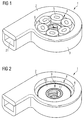
- Figure 1 shows a first embodiment of a centrifugal blood pump with a casing 1 comprising an upper shell 2 and a lower shell 3.
- the upper shell 2 as well as the lower shell 3 each have a circular recess 4 accommodating a set of six electromagnetic coils 5 therein.
- the number of coils can be different and is preferably dividable by three.
- the coils 5 do not have any ferromagnetic core. Preferably, they have an oval shape and may alternatively have a trapezoidal shape, so as to fully exploit the available space within the recess 4.
- the coils 5 are encapsulated in a polymer matrix directly on a very thin circular ceramic plate 6 having a thickness of only about 100 ⁇ m.
- the ceramic plate 6 has a central hole 7 constituting a blood flow inlet through which blood can enter the blood pump when the blood pump is appropriately connected e.g. to the apex of the left ventricle. The blood will exit the blood pump through the blood flow outlet 21.
- the ceramic plate 6 with the electromagnetic coils 5 mounted thereon together form a unitary coil assembly.
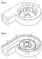
- FIG. 2 shows the blood pump of Figure 1 without the coil assembly 5, 6.
- the recess 4 in the upper shell 2 of the pump casing 1 has a ledge 8 on which the ceramic plate 6 rests.
- the ledge 8 defines a step or further recess within the recess 4, within which the impeller 9 is accommodated so that it can rotate about a central axis of the pump casing 1.
- the impeller 9 comprises an upper magnetic disc 10 and a lower magnetic disc (not shown) and further a blade rotor 11 sandwiched between the two magnetic discs 10.
- the upper and lower surfaces of the impeller 9 and the axially inner surfaces of the upper and lower ceramic plates 6 of the two coil assemblies define a limited axial clearance within which the impeller 9 is freely axially movable.
- the radially outer circumference of the impeller 9 together with the lower inner surface of the stepped recess 4 define a radial clearance within which the impeller 9 is freely radially movable.
- the lower wall 12 of the recess 4 limiting the radial clearance for the impeller 9 can be seen better in Figure 3 .
- the wall 12 has through openings 13 through which blood being radially propelled by the impeller can pass into a ring diffuser arranged peripherally of the wall 12.
- the wall may alternatively be composed of axially extending, spaced apart wall sections providing through openings therebetween.
- the wall 12 is further provided with pockets 14 which are configured to enhance a hydrodynamic radial bearing effect on the impeller 9, when the impeller rotates about the pump casing's central axis.
- pockets 14 which are configured to enhance a hydrodynamic radial bearing effect on the impeller 9, when the impeller rotates about the pump casing's central axis.
- the radial clearance defined between the impeller's 9 outer circumference and the inner surface of the wall 12 radially converges, as seen in the direction of rotation of the impeller, which is indicated in Figure 3 by an arrow.
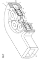
- FIG 4 shows the lower shell 3 with the blade rotor 11, the upper and lower magnetic discs 10 of the impeller 9 being removed.
- the blade rotor 11 has three radially extending blades 15 held together by a central circular ring 16 and two upper and lower circumferential rings 17,18. Passages 19 are defined between the blades 15 for blood to flow radially from a blood flow inlet, corresponding to the central hole 7, to the ring diffuser 20 arranged peripherally of the blade rotor 11 and further to a blood flow outlet 21 of the pump casing.
- the upper and lower circumferential rings 17,18 Upon rotation of the impeller 9, the upper and lower circumferential rings 17,18 will slide along the wall 12, namely above and below the wall's 12 through openings 13, whereas the radially outer surfaces 22 of the blade 15 and the passages 19 defined therebetween will pass along the through openings 13 of the wall 12 (see Figure 3 ).
- the distances between two adjacent through openings 13 in the wall 12 (or between corresponding axially extending wall sections) are dimensioned so that they are smaller than all distances between the radially outer ends of the blades 15 of the blade rotor 11. In this way, pulsation of the blood flow through the impeller 9 can be avoided, as the blood flow passages of the impeller are always open in a radially outward direction.
- Figure 5 shows an alternative upper shell 2' which differs from the upper shell 2 in Figure 3 in that it has a larger number of through openings 13 and, more importantly, the inner surface of the wall 12 lacks pockets 14. A hydrodynamic radial bearing will nevertheless be established once the impeller 9 is set rotating.
- the wall 12 may be divided into an upper circular wall section forming part of the upper shell 2 and a lower circular wall section of the lower shell 3, each wall section preferably being provided with the afore-mentioned pockets 14, a continuous circular through opening 13 being formed between the two circular wall sections.
- Figure 6 shows the lower shell 3 of the pump casing 1 with only the lower coil assembly 5, 6 positioned in a recess (not shown) of the lower shell 3.
- the central opening 7 in the coil assembly 5, 6 can be provided on one or both coil assemblies, thus allowing axial blood inflow from only one side or on both sides of the impeller.
- FIG. 7 shows a cross-sectional view of the blood pump described above with all elements accordingly numbered.
- the upper and lower coil assemblies 5, 6 are identical in size and structure.
- the lower ceramic plate 6 can be supported on the free end of the wall 12 of the upper shell 2.
- the blade rotor 11 of the impeller 9 carrying a magnetic disc 10 on each side is cut at one side through a blade 15 and at the other side through a passage 19 defined between two blades 15.
- the cross section of the ring diffuser 20 increases in the circumferential direction of the blood pump in this embodiment.
- Figure 8 shows the blade rotor 11 separately, including the blades 15 and their radially outer surfaces 22, the through openings 13 defined between the blades 15, the central circular ring 16 as well as the upper and lower circumferential outer rings 17 and 18 connecting the blades 15 to form an integral piece, which is preferably injection moulded.
- the blades 15 of the impeller 9 have an axially extending leading edge 23, as seen in the direction of rotation of the impeller, which is curved or tapered in order to enhance the hydrodynamic effect of the radially outer surfaces 22 and reduce blood damage.
- the number of blades 15 can be more than three, e.g. four, five or six.
- the angular extension ⁇ of the blades may be larger or smaller than shown in Figure 8 .
- the inner diameter of the blades may be larger or smaller than shown in Figure 8 .
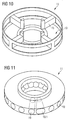
- Figures 9 , 10 and 11 show a first, a second and a third variant of the blade rotor 11.
- the blade rotor 11 in Figure 9 differs from the blade rotor 11 in Figure 8 in that the upper and lower circumferential rings 17,18 are interrupted.
- the hydrodynamic radial bearing for the impeller 9 is achieved with this variant of the blade rotor 11 mainly by the radially outer surfaces 22 of the blades 15.
- the magnetic disc 10 (not shown in Figure 9 ) may be formed such that it fills the space of the missing sections of the upper and lower circumferential rings 17,18.
- the blades 15 of the impeller have an axially extending leading edge, as seen in the direction of rotation of the impeller, which is curved or tapered in order to increase the hydrodynamic effect for the hydrodynamic radial bearing of the impeller and in order to reduce blood damage.
- Figure 10 shows a second variant of the blade rotor 11 in which the blades 15 are formed as straight bars, so that the passages 19 defined between adjacent blades 15 are accordingly increased.
- the blade rotor 11 in Figure 11 is formed from a polymeric washer-like disc having a number of radially extending passages 19 which may overlap in a central area of the blade rotor 11.
- the radial passages 19 may have a constant cross section or, as shown at 19.1, may have a cross section which increases towards the outer circumference.
- the magnetic discs 10 are magnetized in sections in opposite directions. Each section has a first pole at the upper side of the disc and the respective opposite pole on the lower side of the disc.
- the number of magnetized sections is preferably eight but may likewise be four or twelve and should be different from the number of coils 5.
- the radial dimensions of the circular magnetic discs 10 may be such that the outer circumferential radial surfaces of the magnetic discs replace the upper and lower circumferential rings 17,18.
- the blades 15 are interconnected only by the central circular ring 16. The advantage is that more magnetic material is present, so that the maximum torque provided by the impeller may accordingly be increased.
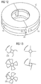
- FIG 12 shows a further variant of an impeller that can be used in connection with the blood pump according to the first embodiment.
- the impeller is entirely made from permanently magnetized ferromagnetic material, i.e. not only the upper and lower magnetic discs 10 but also the radially extending blades 15 are magnetic.
- the blades 15 have an axially extending leading edge 23, as seen in the direction of rotation of the impeller, which is curved or tapered in order to reduce blood damage.
- the rotor may be encapsulated or shielded by a polymeric or metal housing. The encapsulation can be provided in a polymeric moulding process or by galvanic metal deposition.
- the blade rotor 11 may have more than three blades 15, and the form of the blades 15 need not be triangular or trapezoidal or straight.
- Figure 13 schematically shows top views of various blade rotor forms. Among these forms, blade rotors with curved blades are preferred. It is particularly preferred when the leading surface 22b of the impeller blades 15, as seen in the direction of rotation of the impeller, is convex with respect to its radial extension.
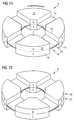
- Figure 14 shows a first variant of an impeller 9 of a second embodiment of a blood pump.
- the pump casing 1, upper shell 2, lower shell 3, recesses 4, coil assemblies comprising the coils 5 and ceramic plates 6, wall 12 or wall sections within the pump casing 1, through openings 13 extending through the wall 12 or between corresponding wall sections, ring diffuser 20 and blood flow outlet 21 in the second embodiment are identical to those of the first embodiment described above.
- the only difference in the second embodiment is the impeller 9, which comprises only one disc 10 with a central opening 7, rather than two magnetic discs 10.
- the disc 10 in the second embodiment is centrally arranged, as seen in an axial direction, and may or may not be magnetic.
- the blades 15 of the impeller 9 extend axially from both axial sides of the disc 10 and are formed as magnets or may have magnetic regions. Blood flow passages 19 are defined between adjacent blades 15.
- the wall 12 or wall sections arranged within the pump casing may be formed as a radially inward extending wall arranged horizontally, so as to form together with the circular radially outer surface of the central disc 10 the afore-described hydrodynamic radial bearing.
- both the blades 15 and the disc 10 of the impeller 9 are made from magnetized material.
- the borders between adjacent magnetized regions are indicated by dotted lines.
- the direction of rotation of the impeller 9 is indicated by an arrow.
- the axially extending leading edges of the blades 15 are rounded or tapered so as to enhance the radial hydrodynamic bearing effect and reduce blood damage.
- the horizontal leading edges 24 of the blades 15 are also rounded or tapered to enhance the axial hydrodynamic bearing effect and reduce blood damage.
- the upper and lower axial surfaces 25 of the blades are slightly tapered so as to provide a circumferentially extending ramp to create a hydrodynamic axial force lifting the impeller from the respective adjacent wall (not shown) upon rotation of the impeller.
- the radially outer surfaces 22 of the blades 15 may likewise change from a smaller radius to a larger radius, as seen in the direction of rotation of the impeller, so as to form, together with the circular wall 12 or circularly arranged wall sections in the pump casing 1, radially converging clearance sections, so as to enhance the radial hydrodynamic bearing effect on the impeller.
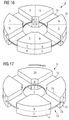
- Figure 15 shows a second variant of the impeller 9 similar to that shown in Figure 14 , except that the disc 10 and the blades 15 are composed of two semi-shells 26, 27 within which the magnets are housed.
- the semi-shells 26, 27 may be injection moulded.
- Figure 16 shows a third variant of the impeller 9 of the second embodiment, similar to the variant shown in Figure 15 .
- two magnets are housed within each of the blades 15, the alternation of the north and south poles of the respective magnets being indicated with N and S.
- both the blades 15 and the disc 10 may be integrally formed from ferromagnetic material and magnetized in sections , as described above in relation to Figure 14 .
- FIG. 17 a fourth variant of the impeller 9 of the second embodiment is shown in Figure 17 .
- This variant is similar to the variant shown in Figure 14 , except that the disc 10 is not necessarily made from a magnetized material.
- the disc 10 may instead be made of a polymer and has a plurality of circularly arranged axial through openings into which the blades 15 are inserted so that they extend from one axial side of the disc 10 to the other axial side thereof.
- the blades 15 may have a different axial cross section, similar to one of those schematically shown in Figure 13 . However, since only the upper and lower axial surfaces of the blades 15 contribute to the hydrodynamic axial bearing in the second embodiment, blades 15 with a large axial cross section are preferred.
Claims (16)
- Pompe à sang centrifuge sans palier mécanique, comprenant :- un corps de pompe (1) à axe central, une entrée de débit sanguin agencée sur l'axe central et une sortie de débit sanguin (21) agencée sur une circonférence du corps de pompe,- une hélice (9) agencée dans le corps de pompe de façon à pouvoir tourner autour dudit axe central et pouvant se déplacer librement axialement et radialement à l'intérieur d'un jeu axial restreint et d'un jeu radial restreint, l'hélice étant fournie avec des aimants permanents ou des régions magnétiques à aimantation permanente (N/S) et de plus avec des pales s'étendant radialement (15) définissant des passages intermédiaires pour le débit sanguin radial, et- un entraînement électromagnétique (5) adapté pour coopérer avec les aimants ou les régions magnétiques (N/S) de l'hélice afin de mettre l'hélice en rotation autour dudit axe central.dans laquelle ledit jeu radial est défini par une circonférence externe (17, 18, 22) de l'hélice et une surface interne d'une paroi (12), ou une pluralité de sections de paroi, agencée de manière circulaire autour dudit axe central, le jeu radial étant de 100 µm ou moins afin de former un palier radial hydrodynamique pour l'hélice, caractérisé en ce que la paroi ou la pluralité de sections de paroi est agencée à l'intérieur du corps de pompe (1) et la pompe comprend une bague de diffuseur (20) agencée à la périphérie de ladite paroi (12) ou desdites sections de paroi.
- Pompe à sang centrifuge selon la revendication 1, dans laquelle le jeu radial comprend une pluralité de sections de jeu à convergence radiale (14), comme représenté dans le sens de rotation de l'hélice.
- Pompe à sang centrifuge selon la revendication 1 ou 2, dans laquelle l'entraînement électromagnétique comprend une pluralité de bobines (5) sans noyau ferromagnétique, les bobines étant agencées sur un plan espacé axialement de l'hélice (9).
- Pompe à sang centrifuge selon la revendication 3, dans laquelle les bobines (5) sont montées directement ou indirectement sur une plaque en céramique (6) de façon à former un élément à part entière de celle-ci, la plaque restreignant ledit jeu axial.
- Pompe à sang centrifuge selon l'une quelconque des revendications 1 à 4, dans laquelle l'hélice (9) comprend un premier disque (10) et un second disque (10) espacés axialement, chaque disque ayant des régions magnétiques et une ouverture centrale (7) agencée pour le débit sanguin axial à travers les premier et second disques, les pales (15) de l'hélice (9) étant agencées entre les disques (10).
- Pompe à sang centrifuge selon la revendication 5, dans laquelle les pales (15) sont entièrement reliées par au moins un bord circulaire (17, 18) s'étendant axialement d'un côté axial ou des deux côtés axiaux des pales (15) et entourant une circonférence externe au moins de l'un ou des deux desdits premier et second disques (10), ledit bord circulaire (17, 18) formant une partie ou la totalité de ladite circonférence externe de l'hélice (9).
- Pompe à sang centrifuge selon la revendication 5, dans laquelle au moins l'un ou les deux desdits premier et second disques (10) présentent une circonférence externe circulaire qui forme une partie ou la totalité de ladite circonférence externe de l'hélice (9).
- Pompe à sang centrifuge selon l'une quelconque des revendications 1 à 4, dans laquelle l'hélice (9) comprend un disque (10) à ouverture centrale (7) agencée pour le débit sanguin axial à travers le disque et dans laquelle les pales (15) de l'hélice s'étendent axialement des deux côtés axiaux du disque (10) et sont formées sous forme d'aimants ou présentent des régions magnétiques (N/S).
- Pompe à sang centrifuge selon la revendication 8, dans laquelle le disque (10) présente une surface radiale externe circulaire et dans laquelle ladite paroi s'étend radialement vers l'intérieur afin de créer avec la surface radiale externe circulaire du disque ledit palier radial hydrodynamique.
- Pompe à sang centrifuge selon la revendication 8 ou 9, dans laquelle le disque (10) a une pluralité d'ouvertures traversantes axiales agencées de manière circulaire et dans laquelle les pales (15) sont introduites dans les ouvertures traversantes axiales agencées de manière circulaire afin de s'étendre d'un côté axial du disque vers l'autre côté axial de celui-ci.
- Pompe à sang centrifuge selon la revendication 8 ou 9, dans laquelle le disque (10) et les pales (15) se composent de deux demi-coques (26, 27) à l'intérieur desquelles se logent les aimants.
- Pompe à sang centrifuge selon l'une quelconque des revendications 1 à 11, dans laquelle les pales (15) de l'hélice (9) sont formées ensemble d'un seul tenant sous forme d'une pièce intégrale moulée par injection (11).
- Pompe à sang centrifuge selon l'une quelconque des revendications 8 à 10, dans laquelle le disque (10) et les pales (15) sont constitués d'un matériau ferromagnétique aimanté.
- Pompe à sang centrifuge selon la revendication 8 ou 9, dans laquelle le disque (10) et les pales (15) sont formés d'un seul tenant sous forme d'une pièce de matériau ferromagnétique, ladite pièce, y compris le disque (10), étant aimantée.
- Pompe à sang centrifuge selon l'une quelconque des revendications 1 à 14, dans laquelle la dimension radiale d'au moins une ou de toutes les pales (15) augmente circonférentiellement, les surfaces radiales externes (22) de ces pales formant une partie ou la totalité de ladite circonférence externe de l'hélice (9).
- Pompe à sang centrifuge selon l'une quelconque des revendications 1 à 15, dans laquelle l'hélice (9) présente un rapport diamètre/hauteur de 4:1 ou plus.
Priority Applications (13)
| Application Number | Priority Date | Filing Date | Title |
|---|---|---|---|
| EP12188316.9A EP2719403B1 (fr) | 2012-10-12 | 2012-10-12 | Pompe sanguine centrifuge |
| EP13777019.4A EP2906265B1 (fr) | 2012-10-12 | 2013-10-11 | Pompe sanguine centrifuge |
| KR1020227002934A KR102486752B1 (ko) | 2012-10-12 | 2013-10-11 | 원심 혈액 펌프 |
| JP2015536148A JP6118910B2 (ja) | 2012-10-12 | 2013-10-11 | 遠心血液ポンプ |
| CN201710260090.1A CN107252504B (zh) | 2012-10-12 | 2013-10-11 | 离心血泵 |
| CN201380053302.9A CN104703637B (zh) | 2012-10-12 | 2013-10-11 | 离心血泵 |
| KR1020157012029A KR102250277B1 (ko) | 2012-10-12 | 2013-10-11 | 원심 혈액 펌프 |
| PCT/EP2013/071273 WO2014057087A1 (fr) | 2012-10-12 | 2013-10-11 | Pompe sanguine centrifuge |
| US14/433,135 US11092158B2 (en) | 2012-10-12 | 2013-10-11 | Centrifugal blood pump with hydrodynamic bearing |
| KR1020217031394A KR102357702B1 (ko) | 2012-10-12 | 2013-10-11 | 원심 혈액 펌프 |
| KR1020217013105A KR102309738B1 (ko) | 2012-10-12 | 2013-10-11 | 원심 혈액 펌프 |
| JP2017061178A JP6360937B2 (ja) | 2012-10-12 | 2017-03-27 | 遠心血液ポンプ |
| US17/355,880 US20220042511A1 (en) | 2012-10-12 | 2021-06-23 | Centrifugal blood pump with hydrodynamic bearing |
Applications Claiming Priority (1)
| Application Number | Priority Date | Filing Date | Title |
|---|---|---|---|
| EP12188316.9A EP2719403B1 (fr) | 2012-10-12 | 2012-10-12 | Pompe sanguine centrifuge |
Publications (2)
| Publication Number | Publication Date |
|---|---|
| EP2719403A1 EP2719403A1 (fr) | 2014-04-16 |
| EP2719403B1 true EP2719403B1 (fr) | 2016-09-28 |
Family
ID=47018072
Family Applications (2)
| Application Number | Title | Priority Date | Filing Date |
|---|---|---|---|
| EP12188316.9A Active EP2719403B1 (fr) | 2012-10-12 | 2012-10-12 | Pompe sanguine centrifuge |
| EP13777019.4A Active EP2906265B1 (fr) | 2012-10-12 | 2013-10-11 | Pompe sanguine centrifuge |
Family Applications After (1)
| Application Number | Title | Priority Date | Filing Date |
|---|---|---|---|
| EP13777019.4A Active EP2906265B1 (fr) | 2012-10-12 | 2013-10-11 | Pompe sanguine centrifuge |
Country Status (6)
| Country | Link |
|---|---|
| US (2) | US11092158B2 (fr) |
| EP (2) | EP2719403B1 (fr) |
| JP (2) | JP6118910B2 (fr) |
| KR (4) | KR102486752B1 (fr) |
| CN (2) | CN107252504B (fr) |
| WO (1) | WO2014057087A1 (fr) |
Cited By (5)
| Publication number | Priority date | Publication date | Assignee | Title |
|---|---|---|---|---|
| US10722631B2 (en) | 2018-02-01 | 2020-07-28 | Shifamed Holdings, Llc | Intravascular blood pumps and methods of use and manufacture |
| US11185677B2 (en) | 2017-06-07 | 2021-11-30 | Shifamed Holdings, Llc | Intravascular fluid movement devices, systems, and methods of use |
| US11511103B2 (en) | 2017-11-13 | 2022-11-29 | Shifamed Holdings, Llc | Intravascular fluid movement devices, systems, and methods of use |
| US11654275B2 (en) | 2019-07-22 | 2023-05-23 | Shifamed Holdings, Llc | Intravascular blood pumps with struts and methods of use and manufacture |
| US11724089B2 (en) | 2019-09-25 | 2023-08-15 | Shifamed Holdings, Llc | Intravascular blood pump systems and methods of use and control thereof |
Families Citing this family (23)
| Publication number | Priority date | Publication date | Assignee | Title |
|---|---|---|---|---|
| EP2719403B1 (fr) | 2012-10-12 | 2016-09-28 | Abiomed Europe GmbH | Pompe sanguine centrifuge |
| BR102014021617B1 (pt) * | 2014-09-01 | 2023-04-11 | Mundial S/A Produtos De Consumo | Motobomba de mancal flutuante arrefecida por um fluido circulante |
| JP2016188593A (ja) * | 2015-03-30 | 2016-11-04 | Ntn株式会社 | 遠心式ポンプ装置 |
| JP2016188591A (ja) * | 2015-03-30 | 2016-11-04 | Ntn株式会社 | 遠心式ポンプ装置 |
| WO2016158172A1 (fr) * | 2015-03-30 | 2016-10-06 | Ntn株式会社 | Dispositif de pompe centrifuge |
| JP2016188590A (ja) * | 2015-03-30 | 2016-11-04 | Ntn株式会社 | 遠心式ポンプ装置 |
| EP3173108B1 (fr) * | 2015-11-30 | 2018-09-26 | Fundacja Rozwoju Kardiochirurgii Im. Prof. Zbigniewa Religi | Rotor avec des canaux fermés pour une pompe d'assistance ventriculaire centrifuge implantable |
| EP3222301B1 (fr) * | 2016-03-23 | 2018-05-09 | Abiomed Europe GmbH | Pompe sanguine |
| US10377097B2 (en) * | 2016-06-20 | 2019-08-13 | Terumo Cardiovascular Systems Corporation | Centrifugal pumps for medical uses |
| DE102018201030A1 (de) | 2018-01-24 | 2019-07-25 | Kardion Gmbh | Magnetkuppelelement mit magnetischer Lagerungsfunktion |
| DE102018211327A1 (de) | 2018-07-10 | 2020-01-16 | Kardion Gmbh | Laufrad für ein implantierbares, vaskuläres Unterstützungssystem |
| CN108895032A (zh) * | 2018-09-07 | 2018-11-27 | 佛山市南海区丹灶恒笙电机厂 | 一种抽水泵 |
| EP3711786A1 (fr) * | 2019-03-19 | 2020-09-23 | Abiomed Europe GmbH | Pompe sanguine |
| CN110439849A (zh) * | 2019-09-17 | 2019-11-12 | 河南瑞昂畜牧科技有限公司 | 泵用叶轮及离心式叶轮泵 |
| WO2021094139A1 (fr) | 2019-11-12 | 2021-05-20 | Fresenius Medical Care Deutschland Gmbh | Systèmes de traitement du sang |
| CA3160952A1 (fr) | 2019-11-12 | 2021-05-20 | Fresenius Medical Care Deutschland Gmbh | Systemes de traitement du sang |
| WO2021094140A1 (fr) | 2019-11-12 | 2021-05-20 | Fresenius Medical Care Deutschland Gmbh | Systèmes de traitement du sang |
| CA3160967A1 (fr) | 2019-11-12 | 2021-05-20 | Fresenius Medical Care Deutschland Gmbh | Systemes de traitement du sang |
| DE102020102474A1 (de) | 2020-01-31 | 2021-08-05 | Kardion Gmbh | Pumpe zum Fördern eines Fluids und Verfahren zum Herstellen einer Pumpe |
| US20220186732A1 (en) * | 2020-12-11 | 2022-06-16 | Sapphire Motors | Integrated pump assembly with one moving part with stacked stator |
| US20220413359A1 (en) * | 2021-06-23 | 2022-12-29 | New Shicoh Motor Co., Ltd. | Blade driving device, camera device and electronic apparatus |
| TW202335698A (zh) * | 2022-01-28 | 2023-09-16 | 德商阿比奥梅德歐洲有限公司 | 血液泵 |
| CN115282470B (zh) * | 2022-07-08 | 2023-08-18 | 深圳核心医疗科技股份有限公司 | 驱动装置和血泵 |
Family Cites Families (34)
| Publication number | Priority date | Publication date | Assignee | Title |
|---|---|---|---|---|
| US2384251A (en) * | 1943-01-14 | 1945-09-04 | Wright Aeronautical Corp | Liquid cooled supercharger |
| US3918829A (en) * | 1974-06-19 | 1975-11-11 | Warren Pumps Inc | Low pressure-pulse kinetic pump |
| JP3853865B2 (ja) | 1996-01-31 | 2006-12-06 | テルモ株式会社 | 遠心式血液ポンプ装置 |
| US6074180A (en) * | 1996-05-03 | 2000-06-13 | Medquest Products, Inc. | Hybrid magnetically suspended and rotated centrifugal pumping apparatus and method |
| US6250880B1 (en) * | 1997-09-05 | 2001-06-26 | Ventrassist Pty. Ltd | Rotary pump with exclusively hydrodynamically suspended impeller |
| DE29821565U1 (de) | 1998-12-02 | 2000-06-15 | Impella Cardiotech Ag | Lagerlose Blutpumpe |
| US6345961B1 (en) * | 1999-01-26 | 2002-02-12 | Fluid Equipment Development Company | Hydraulic energy recovery device |
| JP2002541986A (ja) | 1999-04-23 | 2002-12-10 | ヴェントラシスト・ピーティワイ・リミテッド | ロータリ血液ポンプ及びその制御装置 |
| US6234772B1 (en) * | 1999-04-28 | 2001-05-22 | Kriton Medical, Inc. | Rotary blood pump |
| US6421239B1 (en) * | 2000-06-06 | 2002-07-16 | Chaun-Choung Technology Corp. | Integral heat dissipating device |
| JP2002315824A (ja) | 2001-04-23 | 2002-10-29 | National Institute Of Advanced Industrial & Technology | 人工心臓用回転ポンプ |
| US6653755B2 (en) * | 2001-05-30 | 2003-11-25 | Intel Corporation | Radial air flow fan assembly having stator fins surrounding rotor blades |
| EP1430919A1 (fr) * | 2002-12-17 | 2004-06-23 | Terumo Kabushiki Kaisha | Pompe à sang centrifuge |
| US7022284B2 (en) * | 2003-05-09 | 2006-04-04 | Cardiovention, Inc. | Extracorporeal blood handling system with integrated heat exchanger |
| US7128538B2 (en) * | 2003-07-07 | 2006-10-31 | Terumo Corporation | Centrifugal fluid pump apparatus |
| US7416525B2 (en) | 2003-09-18 | 2008-08-26 | Myrakelle, Llc | Rotary blood pump |
| ATE456963T1 (de) * | 2004-03-24 | 2010-02-15 | Terumo Corp | Zentrifugalblutpumpe mit hydrodynamischer lagerung |
| JP4340182B2 (ja) | 2004-03-31 | 2009-10-07 | テルモ株式会社 | 血液ポンプ装置 |
| JP4340178B2 (ja) * | 2004-03-24 | 2009-10-07 | テルモ株式会社 | 遠心式血液ポンプ装置 |
| US7226277B2 (en) * | 2004-12-22 | 2007-06-05 | Pratt & Whitney Canada Corp. | Pump and method |
| JP4517076B2 (ja) | 2005-06-23 | 2010-08-04 | 独立行政法人産業技術総合研究所 | 動圧軸受を備えた人工心臓ポンプ |
| DE102005039446B4 (de) * | 2005-08-18 | 2009-06-25 | Ilias-Medical Gmbh | Vorrichtung zur An- und Abreicherung von Stoffen in einer Flüssigkeit |
| US8672611B2 (en) * | 2006-01-13 | 2014-03-18 | Heartware, Inc. | Stabilizing drive for contactless rotary blood pump impeller |
| JP5155186B2 (ja) | 2006-01-13 | 2013-02-27 | ハートウェア、インコーポレイテッド | 回転式血液ポンプ |
| JP4898319B2 (ja) * | 2006-06-23 | 2012-03-14 | テルモ株式会社 | 血液ポンプ装置 |
| DE102006036948A1 (de) | 2006-08-06 | 2008-02-07 | Akdis, Mustafa, Dipl.-Ing. | Blutpumpe |
| US8152493B2 (en) * | 2007-04-30 | 2012-04-10 | Hearthware Inc. | Centrifugal rotary blood pump with impeller having a hydrodynamic thrust bearing surface |
| US9044535B2 (en) * | 2007-08-07 | 2015-06-02 | Terumo Cardiovascular Systems Corp. | Extracorporeal blood pump with disposable pump head portion having magnetically levitated impeller |
| WO2011013483A1 (fr) * | 2009-07-29 | 2011-02-03 | Ntn株式会社 | Dispositif de mise en rotation et dispositif de pompe centrifuge |
| US8535212B2 (en) * | 2011-03-30 | 2013-09-17 | Jarvik Robert | Centrifugal blood pumps with reverse flow washout |
| CN202355626U (zh) * | 2011-12-07 | 2012-08-01 | 上海理工大学 | 一种血泵 |
| JP5828459B2 (ja) | 2012-03-30 | 2015-12-09 | 国立研究開発法人産業技術総合研究所 | 遠心血液ポンプ |
| CN102694444B (zh) * | 2012-06-05 | 2014-02-12 | 江苏大学 | 定位力互补式双定子圆筒型直线电机 |
| EP2719403B1 (fr) | 2012-10-12 | 2016-09-28 | Abiomed Europe GmbH | Pompe sanguine centrifuge |
-
2012
- 2012-10-12 EP EP12188316.9A patent/EP2719403B1/fr active Active
-
2013
- 2013-10-11 EP EP13777019.4A patent/EP2906265B1/fr active Active
- 2013-10-11 KR KR1020227002934A patent/KR102486752B1/ko active IP Right Grant
- 2013-10-11 KR KR1020217031394A patent/KR102357702B1/ko active IP Right Grant
- 2013-10-11 WO PCT/EP2013/071273 patent/WO2014057087A1/fr active Application Filing
- 2013-10-11 CN CN201710260090.1A patent/CN107252504B/zh active Active
- 2013-10-11 KR KR1020157012029A patent/KR102250277B1/ko active IP Right Grant
- 2013-10-11 KR KR1020217013105A patent/KR102309738B1/ko active IP Right Grant
- 2013-10-11 US US14/433,135 patent/US11092158B2/en active Active
- 2013-10-11 JP JP2015536148A patent/JP6118910B2/ja active Active
- 2013-10-11 CN CN201380053302.9A patent/CN104703637B/zh active Active
-
2017
- 2017-03-27 JP JP2017061178A patent/JP6360937B2/ja active Active
-
2021
- 2021-06-23 US US17/355,880 patent/US20220042511A1/en active Pending
Cited By (7)
| Publication number | Priority date | Publication date | Assignee | Title |
|---|---|---|---|---|
| US11185677B2 (en) | 2017-06-07 | 2021-11-30 | Shifamed Holdings, Llc | Intravascular fluid movement devices, systems, and methods of use |
| US11717670B2 (en) | 2017-06-07 | 2023-08-08 | Shifamed Holdings, LLP | Intravascular fluid movement devices, systems, and methods of use |
| US11511103B2 (en) | 2017-11-13 | 2022-11-29 | Shifamed Holdings, Llc | Intravascular fluid movement devices, systems, and methods of use |
| US10722631B2 (en) | 2018-02-01 | 2020-07-28 | Shifamed Holdings, Llc | Intravascular blood pumps and methods of use and manufacture |
| US11229784B2 (en) | 2018-02-01 | 2022-01-25 | Shifamed Holdings, Llc | Intravascular blood pumps and methods of use and manufacture |
| US11654275B2 (en) | 2019-07-22 | 2023-05-23 | Shifamed Holdings, Llc | Intravascular blood pumps with struts and methods of use and manufacture |
| US11724089B2 (en) | 2019-09-25 | 2023-08-15 | Shifamed Holdings, Llc | Intravascular blood pump systems and methods of use and control thereof |
Also Published As
| Publication number | Publication date |
|---|---|
| CN104703637A (zh) | 2015-06-10 |
| KR102250277B1 (ko) | 2021-05-10 |
| EP2906265A1 (fr) | 2015-08-19 |
| JP6360937B2 (ja) | 2018-07-18 |
| US20150247503A1 (en) | 2015-09-03 |
| KR20220019067A (ko) | 2022-02-15 |
| JP2015532146A (ja) | 2015-11-09 |
| EP2719403A1 (fr) | 2014-04-16 |
| US20220042511A1 (en) | 2022-02-10 |
| CN104703637B (zh) | 2017-05-03 |
| US11092158B2 (en) | 2021-08-17 |
| WO2014057087A1 (fr) | 2014-04-17 |
| EP2906265B1 (fr) | 2016-07-27 |
| KR102486752B1 (ko) | 2023-01-10 |
| JP6118910B2 (ja) | 2017-04-19 |
| CN107252504A (zh) | 2017-10-17 |
| KR102357702B1 (ko) | 2022-02-08 |
| KR20210053358A (ko) | 2021-05-11 |
| CN107252504B (zh) | 2020-11-13 |
| KR20210125093A (ko) | 2021-10-15 |
| KR102309738B1 (ko) | 2021-10-08 |
| JP2017164503A (ja) | 2017-09-21 |
| KR20150068456A (ko) | 2015-06-19 |
Similar Documents
| Publication | Publication Date | Title |
|---|---|---|
| US20220042511A1 (en) | Centrifugal blood pump with hydrodynamic bearing | |
| EP3222301B1 (fr) | Pompe sanguine | |
| EP0810374B1 (fr) | Ensemble pompe centrifuge | |
| JP6067606B2 (ja) | 回転式血液ポンプ | |
| EP1186310B1 (fr) | Pompe turbo à sang | |
| WO2003006088A1 (fr) | Pompe cardiaque artificielle equipee d'un coussinet hydrodynamique | |
| JP4340183B2 (ja) | 遠心式血液ポンプ装置 | |
| JP2009254436A (ja) | 動圧軸受を備えた人工心臓ポンプ | |
| WO2019044738A1 (fr) | Dispositif de pompe | |
| US20210252276A1 (en) | High efficiency blood pump | |
| AU2012261669B2 (en) | Rotary blood pump | |
| AU2004220728A1 (en) | Improvements in Rotor Stability of a Rotary Pump |
Legal Events
| Date | Code | Title | Description |
|---|---|---|---|
| PUAI | Public reference made under article 153(3) epc to a published international application that has entered the european phase |
Free format text: ORIGINAL CODE: 0009012 |
|
| AK | Designated contracting states |
Kind code of ref document: A1 Designated state(s): AL AT BE BG CH CY CZ DE DK EE ES FI FR GB GR HR HU IE IS IT LI LT LU LV MC MK MT NL NO PL PT RO RS SE SI SK SM TR |
|
| AX | Request for extension of the european patent |
Extension state: BA ME |
|
| 17P | Request for examination filed |
Effective date: 20141015 |
|
| RBV | Designated contracting states (corrected) |
Designated state(s): AL AT BE BG CH CY CZ DE DK EE ES FI FR GB GR HR HU IE IS IT LI LT LU LV MC MK MT NL NO PL PT RO RS SE SI SK SM TR |
|
| 17Q | First examination report despatched |
Effective date: 20150210 |
|
| GRAP | Despatch of communication of intention to grant a patent |
Free format text: ORIGINAL CODE: EPIDOSNIGR1 |
|
| INTG | Intention to grant announced |
Effective date: 20160420 |
|
| GRAS | Grant fee paid |
Free format text: ORIGINAL CODE: EPIDOSNIGR3 |
|
| GRAA | (expected) grant |
Free format text: ORIGINAL CODE: 0009210 |
|
| AK | Designated contracting states |
Kind code of ref document: B1 Designated state(s): AL AT BE BG CH CY CZ DE DK EE ES FI FR GB GR HR HU IE IS IT LI LT LU LV MC MK MT NL NO PL PT RO RS SE SI SK SM TR |
|
| REG | Reference to a national code |
Ref country code: GB Ref legal event code: FG4D |
|
| REG | Reference to a national code |
Ref country code: CH Ref legal event code: EP |
|
| REG | Reference to a national code |
Ref country code: AT Ref legal event code: REF Ref document number: 832195 Country of ref document: AT Kind code of ref document: T Effective date: 20161015 |
|
| REG | Reference to a national code |
Ref country code: IE Ref legal event code: FG4D |
|
| REG | Reference to a national code |
Ref country code: NL Ref legal event code: FP |
|
| REG | Reference to a national code |
Ref country code: DE Ref legal event code: R096 Ref document number: 602012023463 Country of ref document: DE |
|
| REG | Reference to a national code |
Ref country code: FR Ref legal event code: PLFP Year of fee payment: 5 |
|
| REG | Reference to a national code |
Ref country code: LT Ref legal event code: MG4D |
|
| PG25 | Lapsed in a contracting state [announced via postgrant information from national office to epo] |
Ref country code: HR Free format text: LAPSE BECAUSE OF FAILURE TO SUBMIT A TRANSLATION OF THE DESCRIPTION OR TO PAY THE FEE WITHIN THE PRESCRIBED TIME-LIMIT Effective date: 20160928 Ref country code: NO Free format text: LAPSE BECAUSE OF FAILURE TO SUBMIT A TRANSLATION OF THE DESCRIPTION OR TO PAY THE FEE WITHIN THE PRESCRIBED TIME-LIMIT Effective date: 20161228 Ref country code: LT Free format text: LAPSE BECAUSE OF FAILURE TO SUBMIT A TRANSLATION OF THE DESCRIPTION OR TO PAY THE FEE WITHIN THE PRESCRIBED TIME-LIMIT Effective date: 20160928 Ref country code: RS Free format text: LAPSE BECAUSE OF FAILURE TO SUBMIT A TRANSLATION OF THE DESCRIPTION OR TO PAY THE FEE WITHIN THE PRESCRIBED TIME-LIMIT Effective date: 20160928 Ref country code: FI Free format text: LAPSE BECAUSE OF FAILURE TO SUBMIT A TRANSLATION OF THE DESCRIPTION OR TO PAY THE FEE WITHIN THE PRESCRIBED TIME-LIMIT Effective date: 20160928 |
|
| REG | Reference to a national code |
Ref country code: AT Ref legal event code: MK05 Ref document number: 832195 Country of ref document: AT Kind code of ref document: T Effective date: 20160928 |
|
| PG25 | Lapsed in a contracting state [announced via postgrant information from national office to epo] |
Ref country code: LV Free format text: LAPSE BECAUSE OF FAILURE TO SUBMIT A TRANSLATION OF THE DESCRIPTION OR TO PAY THE FEE WITHIN THE PRESCRIBED TIME-LIMIT Effective date: 20160928 Ref country code: GR Free format text: LAPSE BECAUSE OF FAILURE TO SUBMIT A TRANSLATION OF THE DESCRIPTION OR TO PAY THE FEE WITHIN THE PRESCRIBED TIME-LIMIT Effective date: 20161229 Ref country code: SE Free format text: LAPSE BECAUSE OF FAILURE TO SUBMIT A TRANSLATION OF THE DESCRIPTION OR TO PAY THE FEE WITHIN THE PRESCRIBED TIME-LIMIT Effective date: 20160928 Ref country code: BE Free format text: LAPSE BECAUSE OF NON-PAYMENT OF DUE FEES Effective date: 20161031 |
|
| PG25 | Lapsed in a contracting state [announced via postgrant information from national office to epo] |
Ref country code: EE Free format text: LAPSE BECAUSE OF FAILURE TO SUBMIT A TRANSLATION OF THE DESCRIPTION OR TO PAY THE FEE WITHIN THE PRESCRIBED TIME-LIMIT Effective date: 20160928 Ref country code: RO Free format text: LAPSE BECAUSE OF FAILURE TO SUBMIT A TRANSLATION OF THE DESCRIPTION OR TO PAY THE FEE WITHIN THE PRESCRIBED TIME-LIMIT Effective date: 20160928 |
|
| PG25 | Lapsed in a contracting state [announced via postgrant information from national office to epo] |
Ref country code: ES Free format text: LAPSE BECAUSE OF FAILURE TO SUBMIT A TRANSLATION OF THE DESCRIPTION OR TO PAY THE FEE WITHIN THE PRESCRIBED TIME-LIMIT Effective date: 20160928 Ref country code: BE Free format text: LAPSE BECAUSE OF FAILURE TO SUBMIT A TRANSLATION OF THE DESCRIPTION OR TO PAY THE FEE WITHIN THE PRESCRIBED TIME-LIMIT Effective date: 20160928 Ref country code: PL Free format text: LAPSE BECAUSE OF FAILURE TO SUBMIT A TRANSLATION OF THE DESCRIPTION OR TO PAY THE FEE WITHIN THE PRESCRIBED TIME-LIMIT Effective date: 20160928 Ref country code: AT Free format text: LAPSE BECAUSE OF FAILURE TO SUBMIT A TRANSLATION OF THE DESCRIPTION OR TO PAY THE FEE WITHIN THE PRESCRIBED TIME-LIMIT Effective date: 20160928 Ref country code: SM Free format text: LAPSE BECAUSE OF FAILURE TO SUBMIT A TRANSLATION OF THE DESCRIPTION OR TO PAY THE FEE WITHIN THE PRESCRIBED TIME-LIMIT Effective date: 20160928 Ref country code: IS Free format text: LAPSE BECAUSE OF FAILURE TO SUBMIT A TRANSLATION OF THE DESCRIPTION OR TO PAY THE FEE WITHIN THE PRESCRIBED TIME-LIMIT Effective date: 20170128 Ref country code: CZ Free format text: LAPSE BECAUSE OF FAILURE TO SUBMIT A TRANSLATION OF THE DESCRIPTION OR TO PAY THE FEE WITHIN THE PRESCRIBED TIME-LIMIT Effective date: 20160928 Ref country code: PT Free format text: LAPSE BECAUSE OF FAILURE TO SUBMIT A TRANSLATION OF THE DESCRIPTION OR TO PAY THE FEE WITHIN THE PRESCRIBED TIME-LIMIT Effective date: 20170130 Ref country code: SK Free format text: LAPSE BECAUSE OF FAILURE TO SUBMIT A TRANSLATION OF THE DESCRIPTION OR TO PAY THE FEE WITHIN THE PRESCRIBED TIME-LIMIT Effective date: 20160928 Ref country code: BG Free format text: LAPSE BECAUSE OF FAILURE TO SUBMIT A TRANSLATION OF THE DESCRIPTION OR TO PAY THE FEE WITHIN THE PRESCRIBED TIME-LIMIT Effective date: 20161228 |
|
| REG | Reference to a national code |
Ref country code: CH Ref legal event code: PL |
|
| REG | Reference to a national code |
Ref country code: DE Ref legal event code: R097 Ref document number: 602012023463 Country of ref document: DE |
|
| PG25 | Lapsed in a contracting state [announced via postgrant information from national office to epo] |
Ref country code: IT Free format text: LAPSE BECAUSE OF FAILURE TO SUBMIT A TRANSLATION OF THE DESCRIPTION OR TO PAY THE FEE WITHIN THE PRESCRIBED TIME-LIMIT Effective date: 20160928 |
|
| REG | Reference to a national code |
Ref country code: IE Ref legal event code: MM4A |
|
| PG25 | Lapsed in a contracting state [announced via postgrant information from national office to epo] |
Ref country code: DK Free format text: LAPSE BECAUSE OF FAILURE TO SUBMIT A TRANSLATION OF THE DESCRIPTION OR TO PAY THE FEE WITHIN THE PRESCRIBED TIME-LIMIT Effective date: 20160928 Ref country code: CH Free format text: LAPSE BECAUSE OF NON-PAYMENT OF DUE FEES Effective date: 20161031 Ref country code: LI Free format text: LAPSE BECAUSE OF NON-PAYMENT OF DUE FEES Effective date: 20161031 |
|
| PLBE | No opposition filed within time limit |
Free format text: ORIGINAL CODE: 0009261 |
|
| STAA | Information on the status of an ep patent application or granted ep patent |
Free format text: STATUS: NO OPPOSITION FILED WITHIN TIME LIMIT |
|
| PG25 | Lapsed in a contracting state [announced via postgrant information from national office to epo] |
Ref country code: LU Free format text: LAPSE BECAUSE OF NON-PAYMENT OF DUE FEES Effective date: 20161012 |
|
| 26N | No opposition filed |
Effective date: 20170629 |
|
| REG | Reference to a national code |
Ref country code: FR Ref legal event code: PLFP Year of fee payment: 6 |
|
| PG25 | Lapsed in a contracting state [announced via postgrant information from national office to epo] |
Ref country code: IE Free format text: LAPSE BECAUSE OF NON-PAYMENT OF DUE FEES Effective date: 20161012 Ref country code: SI Free format text: LAPSE BECAUSE OF FAILURE TO SUBMIT A TRANSLATION OF THE DESCRIPTION OR TO PAY THE FEE WITHIN THE PRESCRIBED TIME-LIMIT Effective date: 20160928 |
|
| PG25 | Lapsed in a contracting state [announced via postgrant information from national office to epo] |
Ref country code: HU Free format text: LAPSE BECAUSE OF FAILURE TO SUBMIT A TRANSLATION OF THE DESCRIPTION OR TO PAY THE FEE WITHIN THE PRESCRIBED TIME-LIMIT; INVALID AB INITIO Effective date: 20121012 Ref country code: CY Free format text: LAPSE BECAUSE OF FAILURE TO SUBMIT A TRANSLATION OF THE DESCRIPTION OR TO PAY THE FEE WITHIN THE PRESCRIBED TIME-LIMIT Effective date: 20160928 |
|
| PG25 | Lapsed in a contracting state [announced via postgrant information from national office to epo] |
Ref country code: MK Free format text: LAPSE BECAUSE OF FAILURE TO SUBMIT A TRANSLATION OF THE DESCRIPTION OR TO PAY THE FEE WITHIN THE PRESCRIBED TIME-LIMIT Effective date: 20160928 Ref country code: MT Free format text: LAPSE BECAUSE OF NON-PAYMENT OF DUE FEES Effective date: 20161031 Ref country code: MC Free format text: LAPSE BECAUSE OF FAILURE TO SUBMIT A TRANSLATION OF THE DESCRIPTION OR TO PAY THE FEE WITHIN THE PRESCRIBED TIME-LIMIT Effective date: 20160928 |
|
| REG | Reference to a national code |
Ref country code: FR Ref legal event code: PLFP Year of fee payment: 7 |
|
| PG25 | Lapsed in a contracting state [announced via postgrant information from national office to epo] |
Ref country code: TR Free format text: LAPSE BECAUSE OF FAILURE TO SUBMIT A TRANSLATION OF THE DESCRIPTION OR TO PAY THE FEE WITHIN THE PRESCRIBED TIME-LIMIT Effective date: 20160928 Ref country code: AL Free format text: LAPSE BECAUSE OF FAILURE TO SUBMIT A TRANSLATION OF THE DESCRIPTION OR TO PAY THE FEE WITHIN THE PRESCRIBED TIME-LIMIT Effective date: 20160928 |
|
| REG | Reference to a national code |
Ref country code: DE Ref legal event code: R079 Ref document number: 602012023463 Country of ref document: DE Free format text: PREVIOUS MAIN CLASS: A61M0001100000 Ipc: A61M0060000000 |
|
| REG | Reference to a national code |
Ref country code: FR Ref legal event code: PLFP Year of fee payment: 11 |
|
| P01 | Opt-out of the competence of the unified patent court (upc) registered |
Effective date: 20230522 |
|
| PGFP | Annual fee paid to national office [announced via postgrant information from national office to epo] |
Ref country code: NL Payment date: 20230922 Year of fee payment: 12 Ref country code: GB Payment date: 20230920 Year of fee payment: 12 |
|
| PGFP | Annual fee paid to national office [announced via postgrant information from national office to epo] |
Ref country code: FR Payment date: 20230920 Year of fee payment: 12 |
|
| PGFP | Annual fee paid to national office [announced via postgrant information from national office to epo] |
Ref country code: DE Payment date: 20230920 Year of fee payment: 12 |