EP2718534B1 - Dual string section mill - Google Patents
Dual string section mill Download PDFInfo
- Publication number
- EP2718534B1 EP2718534B1 EP12796606.7A EP12796606A EP2718534B1 EP 2718534 B1 EP2718534 B1 EP 2718534B1 EP 12796606 A EP12796606 A EP 12796606A EP 2718534 B1 EP2718534 B1 EP 2718534B1
- Authority
- EP
- European Patent Office
- Prior art keywords
- cutting block
- milling
- tool
- blade
- tool body
- Prior art date
- Legal status (The legal status is an assumption and is not a legal conclusion. Google has not performed a legal analysis and makes no representation as to the accuracy of the status listed.)
- Active
Links
Images







Classifications
-
- E—FIXED CONSTRUCTIONS
- E21—EARTH OR ROCK DRILLING; MINING
- E21B—EARTH OR ROCK DRILLING; OBTAINING OIL, GAS, WATER, SOLUBLE OR MELTABLE MATERIALS OR A SLURRY OF MINERALS FROM WELLS
- E21B29/00—Cutting or destroying pipes, packers, plugs or wire lines, located in boreholes or wells, e.g. cutting of damaged pipes, of windows; Deforming of pipes in boreholes or wells; Reconditioning of well casings while in the ground
- E21B29/002—Cutting, e.g. milling, a pipe with a cutter rotating along the circumference of the pipe
- E21B29/005—Cutting, e.g. milling, a pipe with a cutter rotating along the circumference of the pipe with a radially-expansible cutter rotating inside the pipe, e.g. for cutting an annular window
-
- E—FIXED CONSTRUCTIONS
- E21—EARTH OR ROCK DRILLING; MINING
- E21B—EARTH OR ROCK DRILLING; OBTAINING OIL, GAS, WATER, SOLUBLE OR MELTABLE MATERIALS OR A SLURRY OF MINERALS FROM WELLS
- E21B10/00—Drill bits
- E21B10/26—Drill bits with leading portion, i.e. drill bits with a pilot cutter; Drill bits for enlarging the borehole, e.g. reamers
- E21B10/32—Drill bits with leading portion, i.e. drill bits with a pilot cutter; Drill bits for enlarging the borehole, e.g. reamers with expansible cutting tools
-
- E—FIXED CONSTRUCTIONS
- E21—EARTH OR ROCK DRILLING; MINING
- E21B—EARTH OR ROCK DRILLING; OBTAINING OIL, GAS, WATER, SOLUBLE OR MELTABLE MATERIALS OR A SLURRY OF MINERALS FROM WELLS
- E21B10/00—Drill bits
- E21B10/26—Drill bits with leading portion, i.e. drill bits with a pilot cutter; Drill bits for enlarging the borehole, e.g. reamers
- E21B10/32—Drill bits with leading portion, i.e. drill bits with a pilot cutter; Drill bits for enlarging the borehole, e.g. reamers with expansible cutting tools
- E21B10/322—Drill bits with leading portion, i.e. drill bits with a pilot cutter; Drill bits for enlarging the borehole, e.g. reamers with expansible cutting tools cutter shifted by fluid pressure
Definitions
- Oil and gas wells are ordinarily completed by first cementing metallic casing stringers in the borehole.
- a dual casing string may be employed, for example, including a smaller diameter string deployed internal to a larger diameter string.
- the internal string is commonly cemented to the larger diameter string (i.e., the annular region between the first and second strings is filled or partially filled with cement).
- well abandonment requires a length (e.g ., about 50 meters) of the wellbore casing string to be removed prior to filling the wellbore with a cement plug.
- the casing string is commonly removed via a milling operation that employs a downhole milling tool having a plurality of circumferentially spaced milling/cutting blades that extend radially outward from a tool body.
- the milling tool is deployed on a tool string and rotated in the well bore such that the blades make a circumferential cut in the metallic casing string.
- the tool string is then urged downhole while rotation continues so as to axially mill the casing string to the desired length.
- milling tools are commonly employed in downhole milling operations, their use is not without certain drawbacks.
- milling a dual-string wellbore typically requires the tool string to be tripped out of the wellbore after milling the smaller diameter string so as to install larger diameter blades.
- a separate drilling operation may also be required to remove the cement layer located between the inner and outer strings.
- larger diameter milling blades can also be problematic in that the larger blades are subject to increased shear and torsional loads and therefore more prone to failure ( e.g., via fracturing or circumferentially wrapping around the tool body). Moreover, for this reason, the use of larger diameter milling blades does not generally enable simultaneous removal of the cement layer and one or both of the casing strings. Larger diameter blades are also difficult to fully collapse into a tool body. Hence, tripping a tool having larger diameter blades can be problematic as the larger blades may hang up in smaller diameter casing (even when collapsed into the tool body).
- a milling tool capable of being deployed in a dual-string wellbore in a single trip, and preferably capable of simultaneously removing a cement layer and milling at least one casing string.
- U.S Patent No. 5,899,268 A describes a tool for cutting or milling casing.
- the tool includes multiple pivoting blades that pivot around a pin to extend the bottom portion of the blades outwardly to cut the walls of casing string.
- Cutting elements on the blades are positioned on leading faces of the blades to engage the casing strings in a cutting action.
- Soviet Union Patent No. 926233 A1 illustrates a deep-well pipe cutter and miller that cuts wellbore casing.
- the tool includes a tool body and multiple pivoting blades that pivot around a pin to extend the bottom portion of the blades outwardly to cut the casing string.
- One or more embodiments include a casing section milling tool (e.g., a dual string casing mill) having at least one milling structure.
- the at least one milling structure includes a cutting block deployed in an axial recess in a tool body.
- the cutting block is configured to extend radially outward from and retract radially inward towards the tool body.
- the cutting block is further configured to remove a cement layer in a wellbore.
- the milling structure further includes a milling blade deployed in an axially slot disposed in the cutting block.
- the milling blade is configured to extend radially outward from and inwards towards the cutting block.
- the milling blade is further configured to cut and mill a section of a casing string in a wellbore.
- the cutting block and milling blade are configured to extend in first, second, and third stages.
- the cutting block extends outward from the tool body while the milling blade remains retracted, or substantially retracted, within the cutting block.
- the cutting block continues to extend outward from the tool body while a first axial end portion of the milling blade pivots radially outward from the cutting block. This pivoting action is intended to bring an outer cutting surface of the milling blade into contact with a casing string.
- the cutting block continues to extend outward from the tool body while a second opposing axial end portion of the milling blade extends outward from the cutting block.
- Exemplary embodiments of the present disclosure provide several technical advantages. For example, one or more embodiments enable the simultaneous removal of a cement layer and the milling of an outer casing string in certain dual-string wellbores. Such simultaneous actions save time and reduce operational costs. Moreover, the configuration of the milling structure in which a milling blade extends radially outward from a cutting block reduces loads on the milling blades and thereby improves the reliability and durability of the tool in service.
- One or more embodiments may also include distinct cutting structures for removing a cement layer and milling an outer casing string.
- the use of distinct cutting structures advantageously allows such cutting structures to be tailored so as to most efficiently remove cement and/or remove casing.
- the cutting block may be configured for removing cement while the milling blade is configured for milling steel.
- an optimal performance for cement removal and casing milling may be achieved while ensuring that the respective cutting structures have a suitably long service life.
- a milling tool i.e., a casing section mill or a dual string section mill
- the tool body has a central axis therethrough and is configured to couple with a tool string.
- the at least one cutting block is arranged and designed to extend radially outward relative to the central axis of the tool body to a cutting block extended position and retract radially inward from the cutting block extended position towards the central axis of the tool body.
- At least one milling blade is deployed in an axial slot disposed in the cutting block.
- the at least one milling blade is arranged and designed to extend radially outward from the cutting block to a milling blade extended position and retract radially inward from the milling blade extended position towards the cutting block.
- a milling tool i.e., a casing section mill or a dual string section mill
- a cutting block deployed in a recess disposed in a tool body of the milling tool.
- the tool body has a central axis therethrough and is configured to couple with a tool string.
- the cutting block is configured to extend radially outward relative to the central axis of the tool body to a cutting block extended position and retract radially inward from the cutting block extended position towards the central axis of the tool body.
- a milling blade is deployed in a slot disposed in the cutting block and is configured to extend radially outward from the cutting block to a mill blade extended position and retract radially inward from the milling blade extended position towards the cutting block.
- a spring is deployed in the tool body and is configured to bias the cutting block in a first axial direction. The spring bias also biases the cutting block radially inward towards the tool body.
- a piston is deployed in the tool body and is configured to urge the cutting block in a second axial direction against the bias of the spring. The piston is responsive to a differential hydraulic pressure in the tool body.
- a milling tool is rotated at a starting downhole position in a well bore.
- the milling tool includes a cutting block deployed in a tool body and a milling blade deployed in the cutting block.
- the cutting block is arranged and designed to extend radially outward from a central axis of the tool body and the milling blade is arranged and designed to extend radially outward from the cutting block.
- the cutting block is extended radially outward from the central axis of the tool body while the milling blade remains retracted in the cutting block.
- At least a portion of a cement layer on an inner surface of an outer casing string at the starting downhole position is removed with the cutting block in its extended position.
- a first axial end portion of the milling blade is pivoted radially outward from the cutting block.
- the outer casing string is cut with the first axial end portion of the milling blade in its extended position.
- a second axial end portion of the milling blade is extended radially outward from the cutting block.
- At least a portion of the outer casing string at the starting downhole position is removed with the second axial end portion of the milling blade in its extended position.
- the milling tool is urged in a downhole direction while the cutting block and the milling blade remain extended, such that translation of the milling tool in the downhole direction causes the cutting block and the milling blade to simultaneously remove cement layer and mill outer casing string.
- FIGURES 1 through 8D it will be understood that features or aspects of the one or more embodiments illustrated may be shown from various views. Where such features or aspects are common to particular views, they are labeled using the same reference numeral. Thus, a feature or aspect labeled with a particular reference numeral on one view in FIGURES 1 through 8D may be described herein with respect to that reference numeral shown on other views.
- FIGURE 1 depicts one exemplary embodiment of a downhole tool 100 (i.e., a casing section mill or a dual string section mill) deployed in a cased wellbore 40.
- a rig 20 is positioned in the vicinity of a subterranean oil or gas formation.
- the rig 20 may include, for example, a derrick and a hoisting apparatus for lowering and raising various components into and out of the wellbore 40.
- the wellbore 40 is at least partially cased with a string of metallic liners 50.
- a tool string 80 including a downhole tool 100, configured in accordance with the present disclosure, is depicted as being run into the wellbore.
- Downhole tool 100 includes at least one cutting block and milling blade combination (not shown) that is configured for milling the casing string 50. It will be understood that tool string 80 may include other suitable components and other downhole tools as needed for a particular downhole operation and that the embodiments disclosed herein are not limited to any particular rig configuration, derrick, or hoisting apparatus.
- FIGURES 2A and 2B depict perspective and partially exploded views of downhole tool 100.
- downhole tool 100 includes a tool body 110 including uphole and downhole threaded end portions 112 and 113 suitable for coupling with a drill string (or other tool string).
- a plurality of circumferentially-spaced cutting blocks 150 are deployed in corresponding axial recesses 115 disposed or formed in the tool body 110.
- the cutting blocks 150 are configured to move between radially retracted (as depicted on FIGURE 2A ) and radially extended positions as described in more detail below with respect to FIGURES 3A-6C .
- a milling blade 170 is deployed in an axial slot 152 in each of the cutting blocks 150 and biased radially inward towards the tool axis.
- the milling blades 170 are also configured to move between radially retracted (as depicted on FIGURE 2A ) and radially extended positions ( FIGURE 2B ).
- downhole tool 100 is described in more detail with respect to a single cutting block and milling blade. It will be understood by those skilled in the art that tools in accordance with the present disclosure preferably, although not necessarily, include multiple cutting blocks and milling blades.
- Cutting block 150 includes a plurality of angled splines 154 formed on the lateral sides thereof.
- the splines 154 are sized and shaped to engage corresponding angled splines 118 formed on the lateral sides of the axial recess 115. Interconnection between splines 154 and splines 118 advantageously increases the contact surface area between the cutting block 150 and the tool body 110, thereby providing a more robust structure suitable for downhole casing milling and/or cement removal operations.
- the splines 118, 154 are angled such that the splines 118, 154 are not parallel with a longitudinal or central axis of the downhole tool 100.
- the splines 118, 154 are angled such that the block 150 is radially extended via uphole axial motion of the block 150 with respect to the tool body 110.
- the splines 118, 154 may be disposed at substantially any suitable angle as the embodiments disclosed herein are not limited in this regard.
- At least a nose portion 155 of the cutting block 150 is fitted with a plurality of cutting elements 157.
- the entire radially facing outer surface (also referred to in the art as the gage surface) of the cutting block 150 may be fitted with cutting elements 157.
- the embodiments of the present disclosure are not limited with respect to the placement or quantity of cutting elements.
- any cutting elements suitable for milling/removing cement may be utilized including, but not limited to, polycrystalline diamond cutter (PDC) inserts, thermally stabilized polycrystalline (TSP) inserts, diamond inserts, boron nitride inserts, abrasive materials, and other cutting elements known to those skilled in the art.
- the cutting block 150 may further include various wear protection measures deployed thereon, for example, including the use of wear buttons, hard facing materials, or various other wear resistant coatings.
- various wear protection measures deployed thereon for example, including the use of wear buttons, hard facing materials, or various other wear resistant coatings.
- the embodiments of the present disclosure are not limited with respect to the quantity, placement or type of wear protection measures or devices deployed thereon.
- Milling blade 170 is deployed in a corresponding axial slot 152 disposed or formed in the cutting block 150.
- the blade 170 is secured to the cutting block 150 via first and second axially spaced pins 172, 173 (in the exemplary embodiment depicted, the pins 172, 173 are located near the downhole and uphole end portions, respectively, of the blade 170) and biased radially inwards via a spring biasing mechanism, e.g., a spring.
- a spring biasing mechanism e.g., a spring.
- the pins 172, 173 engage corresponding slots 162, 163, respectively, formed in the lateral sides of the cutting block 150.
- the slots 162, 163 are shaped such that relative axial motion of the cutting block 150 beyond a predetermined axial location causes a stepwise extension of the milling blade 170 (as described in more detail below).
- the second pin 173 engages a curved slot 163 having a first end portion 163a that faces (or points or is directed) in the uphole direction and a second end portion 163b that faces (or points or is directed) radially outward.
- the first pin 172 engages an angled slot 162 ( i.e., neither parallel nor perpendicular to the longitudinal axis through tool 100) having radially inner and outer end portions 162a, 162b.
- Slot 162 may be substantially perpendicular to the splines 154, for example, as in the depicted embodiment of FIGURE 2D (although the disclosed embodiments are not limited in this regard).
- the angle of slot 162 may be selected so as to predetermine the deployment rate of milling blade 170.
- a steeper-angled slot 162 causes a more rapid deployment but decreases the necessary wedging action when the blade 170 is extended. Thus, there may be a trade off in selecting the angle between achieving a suitable deployment rate and a sufficient wedging action.
- a curved slot 162 (not shown) may also be utilized such that the rate of deployment is variable and depends on the degree of deployment (e.g., such that the rate increases with increasing deployment). Again, the embodiments disclosed herein are not limited in these regards.
- milling blade 170 may be dressed using any known cutting or other materials in the art.
- these surfaces may be substantially or heavily hard faced with a metallurgically-applied tungsten carbide material.
- Other surface treatments may include, for example, disposition of a diamond or cubic boron nitride material, disposition of an embedded natural or polycrystalline diamond, and/or the like. Other suitable surface treatments may be equally employed.
- milling blade 170 is spring biased in the retracted position.
- a compression spring 167 is deployed between an internal surface 159 of the cutting block 150 and a wing 179 of the milling blade 170.
- the spring 167 is angled with respect to the tool axis and therefore biases the blade 170 radially inward and axially uphole with respect to the cutting block 150 such that pin 172 is biased towards end portion 162a of slot 162 and pin 173 is biased towards end portion 163a of slot 163.
- FIGURE 3A depicts a longitudinal cross sectional view of downhole tool 100 (i.e., milling tool 100) with cutting block 150 and milling blade 170 in a retracted, or substantially retracted, position (while FIGURES 3B and 3C depict circular cross sections of downhole tool 100 through pins 173 and 172 respectively).
- Cutting block 150 is deployed axially between spring biasing mechanism 130 and hydraulic actuation mechanism 140 that are also deployed in the tool body 110.
- an internal or inner mandrel 120 is deployed in the tool body 110 at a position internal to the spring mechanism 130, the hydraulic mechanism 140, and the cutting block 150.
- the mandrel 120 includes a central throughbore 122, thereby providing a channel for the flow of drilling fluid/mud through the downhole tool 100.
- the spring biasing mechanism 130 includes a compression spring 132 deployed about the mandrel 120 and axially between an upper cap 133 and a stop ring 135.
- the upper cap 133 is rigidly connected with the tool body 110 such that the compression spring 132 is configured to bias the cutting block 150 in the downhole direction.
- the bias of compression spring 132 also urges the cutting block 150 radially inward (due to the configuration of the angled splines 118, 154).
- Hydraulic actuation mechanism 140 is configured to urge the cutting block 150 in the uphole direction against the spring bias when differential fluid pressure is applied to the bore 122 of the milling tool 100.
- An axial piston 142 is sealingly engaged with an inner surface 111 of the tool body 110 and an outer surface 123 of the mandrel 120. Drilling fluid pressure acts on an axial face 143 of the piston 142, thereby urging it in the uphole direction.
- the piston 142 engages drive ring 145 and retainer 146 which in turn engage cutting block 150 such that translation of the piston 142 causes a corresponding translation and extension of the cutting block 150.
- Hydraulic actuation of the cutting block 150 and milling blade 170 may be initiated using substantially any means known in the art.
- a conventional ball seat (not shown) may be deployed in the tool string 80 ( FIGURE 1 ) below the milling tool.
- a ball may be dropped from the surface onto the ball seat.
- the ball provides an obstruction to the flow of drilling fluid through the tool string 80 which causes an increase in the fluid pressure in the downhole tool 100.
- the pressure increase urges piston 142 uphole against the spring bias, thereby actuating the cutting block 150 and milling blade 170 as described above and in more detail below.
- the fluid pressure in the downhole tool 100 may be increased above some predetermined threshold so as to shear (release) the ball seat and retract the cutting block 150 and milling blade 170 (via spring force provided by compression spring 132).
- the cutting block 150 and milling blade 170 may also be retracted by reducing the fluid pressure below a predetermined threshold.
- the cutting block 150 and milling blade 170 extend radially outward relative to the central axis of the tool body 110 to extended positions in at least first and second stages.
- the cutting block 150 extends radially outward relative to the central axis of the tool body 110 towards a first cutting block extended position while the milling blade 170 remains retracted or at least substantially retracted in the cutting block 150
- both the cutting block 150 and milling blade 170 simultaneously extend radially outward relative to the central axis of the tool body 110 until both are extended or at least substantially extended (i.e., the cutting block 150 is in a second cutting block extended position and milling blade 170 is in a milling blade extended position).
- the cutting block 150 and milling blade 170 extend radially outward relative to the central axis of the tool body 110 to extended positions in first, second and third stages.
- the cutting block 150 extends radially outward relative to the central axis of the tool body 110 towards a first cutting block extended position while the milling blade 170 remains retracted or at least substantially retracted in the cutting block 150.
- cutting block 150 continues to extend radially outward relative to the central axis of the tool body 110 towards a second cutting block extended position while one axial end portion of the milling blade 170 pivots outward beyond the outer surface of the cutting block 150 to a first milling blade extended position.
- cutting block 150 continues to extend radially outward relative to the central axis of the tool body 110 to a third cutting block extended position while the other axial end portion of the milling blade 170 extends radially outward beyond the outer surface of the cutting block 150 to a second milling blade extended position.
- the cutting block 150 and milling blade 170 are extended or at least substantially extended at the end of the third stage.
- FIGURES 4A , 4B, and 4C depict longitudinal and circular cross sectional views of the milling tool 100 at the end of the first stage.
- fluid pressure urges piston 142, and therefore cutting block 150, in the uphole direction against the bias of compression spring 132.
- the engagement of the angled splines 154 and 118 causes the cutting block 150 to extend radially outward as it translates in the uphole direction.
- Milling blade 170 remains biased in a retracted or at least substantially retracted position in the cutting block 150 with pin 172 engaging inner end portion 162a of the angled slot 162 and pin 173 engaging end portion 163a of slot 163.
- an uphole end portion 178 of the milling blade 170 contacts a radially extending fin 126 of stop ring 125.
- the stop ring 125 is deployed about and axially secured with the mandrel 120 such that it does not translate with the cutting block 150 and milling blade 170 during hydraulic actuation of piston 142.
- FIGURES 5A , 5B, and 5C depict longitudinal and circular cross sectional views of the milling tool 100 at the end of the second stage.
- the cutting block 150 continues to translate uphole and radially outward as drilling fluid/mud pressure urges piston 142 in the uphole direction.
- the milling blade 170 abuts stop ring/member 125 (at fin 126) and is thereby restricted from further translation in the uphole direction.
- the abutment of the milling blade 170 with the stop ring/member 125 urges the milling blade 170 against its spring bias (via spring 167) as the cutting block 150 continues to translate uphole past the milling blade 170.
- pin 173 is located at the center (the elbow) of slot 163 and pin 172 is located at the outer end portion 162b of angled slot 162.
- the downhole end portion 176 of the blade 170 is extended or at least substantially extended with respect to the cutting block 150, for example, such that cutting surface 171 contacts or penetrates a wellbore casing string (not shown), e.g., to make a circumferential cut therein.
- the uphole end portion 178 of the blade 170 remains retracted or at least substantially retracted in the cutting block 150.
- FIGURES 6A , 6B, and 6C depict longitudinal and circular cross sectional views of the milling tool 100 at the end of the third stage at which the cutting block 150 and milling blade 170 are extended or at least substantially extended.
- the cutting block 150 continues to translate uphole and radially outward as drilling fluid/mud pressure urges piston 142 in the uphole direction.
- milling blade 170 again translates axially uphole and radially outward with the cutting block 150 as the uphole end portion 178 of the blade 170 slides up (and along) a ramp 128 on the fin portion 126 of stop ring 125.
- Pin 173 slides towards end portion 163b of slot 163 (radially outward from the elbow portion of the slot 163).
- pin 173 is located in end portion 163b of slot 163 while the uphole end portion 178 of the milling blade 170 is radially supported by fin 126.
- the downhole end portion 176 of the blade 170 is supported by the wedging action between the pin 172 and angled slot 162.
- Compression spring 132 may be selected such that it is substantially fully compressed when the cutting block 150 is extended or substantially extended.
- spring 167 may be similarly selected such that it is substantially fully compressed when the milling blade 170 is extended or substantially extended.
- the embodiments of the present disclosure are, of course, not limited in these regards.
- the cutting block 150 advantageously provides circumferential support for the milling blade 170 when extended or substantially extended.
- the milling blade 170 may be thought of as telescoping radially outward from the block 150. Extension of the cutting block 150 outward from the tool body 110 reduces the required extension of the milling blade and thereby reduces milling loads on the milling blade 170. Notwithstanding, support provided by the blocks 150 tends to advantageously minimize structural damage to the blades 170 during casing milling and/or cement removal operations.
- FIGURE 7 depicts a flow chart of one exemplary method embodiment 200 for a dual string section milling operation.
- the exemplary method embodiment 200 depicted includes milling a length of a dual string wellbore including removing the inner and outer casing strings and an annular cement layer located between the strings.
- the inner casing string is first milled at 202, e.g., using a conventional milling tool.
- milling tool 100 is used to simultaneously remove the annular cement layer and mill the outer casing string in steps 204 through 212.
- Milling tool 100 is first positioned at a start location/position at 204. The starting location can be the uphole end portion of the borehole section to be milled.
- the cutting blocks 150 and milling blades 170 are retracted or substantially retracted (as depicted in FIGURE 3 ) while the tool is positioned at 204.
- actuation of milling tool 100 is initiated at 206.
- the cutting blocks 150 are extended into contact with the annular cement layer while the tool rotates in the borehole.
- the cutting blocks 150 continue to extend radially (while the milling blades 170 remain at least partially retracted as depicted on FIGURE 4 ).
- the milling blades 170 begin to pivot radially outward (as depicted on FIGURE 5 ) such that the cutting surface 171 makes an initial cut in the outer casing string at 208.
- the outer casing is then substantially fully removed at the starting location at 210 as the milling blades 170 are further extended (as depicted on FIGURE 6 ).
- the tool string is then urged downhole (while rotating and with the cutting blocks 150 and milling blades 170 extended) so as to simultaneously remove the cement layer and the mill outer casing string at 212.
- the nose portion 155 of the cutting block 150 leads the milling blade 170 downhole (i.e., the nose portion 155 of the cutting block 150 is located downhole of the milling blade 170).
- Such deployment advantageously provides for dual milling functionality in which the cutting block 150 removes the cement layer while the milling blade 170 simultaneously mills the casing string. This deployment also tends to minimize the loading on milling blade 170 as blade 170 is not generally required to simultaneously remove or mill both cement and casing.
- FIGURES 8A-D depict longitudinal cross-sectional views of another milling tool embodiment 300 in accordance with the present disclosure.
- the exemplary embodiment depicted is similar to the downhole tool embodiment 100 described above with respect to FIGURES 2 through 6 with the exception that the downhole tool embodiment 300 of FIGURES 8A-D includes alternative cutting block 350 and milling blade 370 configurations.
- FIGURE 8A depicts a cross-sectional view of milling tool 300 when the cutting block 350 and milling blade 370 are in a collapsed or substantially collapsed position.
- Milling tool 300 is similar to milling tool 100 in that the cutting block 350 and milling blade 370 extend radially outward in first, second, and third stages.
- FIGURE 8B depicts the milling tool 300 at the end of the first stage.
- FIGURE 8C depicts the milling tool 300 at the end of the second stage.
- cutting block 350 continues to extend outward while the other axial end portion of the milling blade 370 extends outward beyond the outer surface of the cutting block 350.
- the cutting block 150 and milling blade 170 are extended or at least substantially extended at the end of the third stage as depicted on FIGURE 8D .
- Cutting block 350 is similar to cutting block 150 in that it includes a plurality of angled splines (not shown) formed on the lateral sides thereof. Cutting block 350 further includes a plurality of cutting elements 357 formed on a nose portion 355 thereof. The cutting elements may be further deployed on the entire gage surface of the cutting block 350 as described in more detail above. Milling blade 370 is deployed in a corresponding axial slot 352 disposed or formed in the cutting block 350 as described above with respect to milling tool 100. An uphole end portion 378 of the blade 370 is coupled to the cutting block 350 via hinge arm 360. As depicted, the blade 370 is pinned to the hinge arm 360 via pin 372 which is in turn pinned to the tool body 310 via pin 362. Pin 362 extends through an angled slot 363 in the cutting block 350 as described in more detail below.
- FIGURE 8B depicts the milling tool 300 at the end of the first stage.
- fluid pressure urges the piston, and therefore the cutting block 350, in the uphole direction against the spring bias.
- the engagement of the angled splines causes the cutting block 350 to extend radially outward as it translates in the uphole direction as described above.
- Milling blade 370 remains substantially axially stationary with respect to the tool body 310 and is optionally biased in a retracted or substantially retracted position in the cutting block 350.
- Cutting block 350 includes an angled slot 363 oriented in the same direction as the angled splines and therefore slides past pin 362 in hinge arm 360 as it translates uphole (and radially outward).
- a downhole end portion 376 of the milling blade 370 begins to contact a ramp 353 at the downhole end portion of slot 352.
- FIGURE 8C depicts the milling tool 300 at the end of the second stage.
- the cutting block 150 continues to translate uphole and radially outward as drilling fluid/mud pressure urges the piston in the uphole direction.
- the milling blade 370 continues to remain substantially axially stationary with respect to the tool body 310 as the downhole end portion 376 of the blade 370 slides up the ramp 353.
- the relative axial motion of the cutting block 350 with respect to the milling blade 370 and the engagement of the blade 370 with the ramp 353 causes the milling blade 370 to pivot about pin 372 in hinge arm 360 such that the downhole end portion 376 of the blade 370 extends radially outward while the uphole end portion 378 of the blade 370 remains retracted radially inward with respect to the cutting block 350.
- the downhole end portion 376 of the blade 370 is at the upper end portion of the ramp 353 and engages notch 354 in the cutting block 350.
- the downhole end portion 376 of the blade 370 is extended with respect to the cutting block 350, for example, such that cutting surface 371 contacts or penetrates a wellbore casing string (not shown).
- the uphole end portion 378 of the blade 370 remains retracted or at least substantially retracted in the cutting block 350.
- FIGURE 8D depicts the milling tool 300 at the end of the third stage at which the cutting block 350 and milling blade 370 are extended or at least substantially extended.
- the cutting block 350 continues to translate uphole and radially outward as drilling fluid/mud pressure urges the piston in the uphole direction.
- the milling blade 370 also translates axially uphole and radially outward with the cutting block 350 as the downhole end portion 376 of the blade 370 engages the notch 354. Such engagement and translation of the milling blade 370 causes the uphole end portion 378 of the blade 370 to pivot radially outward on hinge arm 360.
- the blade 370 is wedged radially outward.
- Pin 362 is located at a radially inner and downhole end portion of slot 363 while hinge arm 360 radially supports the uphole end portion 378 of the blade 370.
- the downhole end portion 376 of the blade 370 is wedged into notch 354. In this configuration, cutting block 350 and milling blade 370 are extended or at least substantially extended with respect to the tool body 310.
- the cutting block 350 and milling blade 370 are advantageously back drivable.
- back drivable it is meant that an uphole force acting on the tool body 310 causes the blade 370 to pivot radially inward as it engages the borehole wall or a narrower section of casing string.
- Such back drivability advantageously tends to prevent the milling tool 300 from becoming lodged in the wellbore should the cutting block 350 and milling blade 370 retraction mechanism fail in service.
Landscapes
- Engineering & Computer Science (AREA)
- Life Sciences & Earth Sciences (AREA)
- Geology (AREA)
- Mining & Mineral Resources (AREA)
- Physics & Mathematics (AREA)
- Environmental & Geological Engineering (AREA)
- Fluid Mechanics (AREA)
- General Life Sciences & Earth Sciences (AREA)
- Geochemistry & Mineralogy (AREA)
- Milling Processes (AREA)
- Mechanical Engineering (AREA)
Description
- Oil and gas wells are ordinarily completed by first cementing metallic casing stringers in the borehole. Depending on the properties of the formation (e.g., formation porosity), a dual casing string may be employed, for example, including a smaller diameter string deployed internal to a larger diameter string. In such dual-string wellbores, the internal string is commonly cemented to the larger diameter string (i.e., the annular region between the first and second strings is filled or partially filled with cement).
- When oil and gas wells are no longer commercial viable, they must be abandoned in accordance with local government regulations. These regulations vary from one jurisdiction to another; however, they generally require one or more permanent barriers to isolate the wellbore. In certain jurisdictions, well abandonment requires a length (e.g., about 50 meters) of the wellbore casing string to be removed prior to filling the wellbore with a cement plug. The casing string is commonly removed via a milling operation that employs a downhole milling tool having a plurality of circumferentially spaced milling/cutting blades that extend radially outward from a tool body. During a typical milling operation, the milling tool is deployed on a tool string and rotated in the well bore such that the blades make a circumferential cut in the metallic casing string. The tool string is then urged downhole while rotation continues so as to axially mill the casing string to the desired length.
- While such milling tools are commonly employed in downhole milling operations, their use is not without certain drawbacks. For example, milling a dual-string wellbore typically requires the tool string to be tripped out of the wellbore after milling the smaller diameter string so as to install larger diameter blades. A separate drilling operation may also be required to remove the cement layer located between the inner and outer strings. These multiple operations and trips are both time consuming and expensive and therefore are undesirable.
- The use of larger diameter milling blades can also be problematic in that the larger blades are subject to increased shear and torsional loads and therefore more prone to failure (e.g., via fracturing or circumferentially wrapping around the tool body). Moreover, for this reason, the use of larger diameter milling blades does not generally enable simultaneous removal of the cement layer and one or both of the casing strings. Larger diameter blades are also difficult to fully collapse into a tool body. Hence, tripping a tool having larger diameter blades can be problematic as the larger blades may hang up in smaller diameter casing (even when collapsed into the tool body).
- As a result, there is a need for a milling tool capable of being deployed in a dual-string wellbore in a single trip, and preferably capable of simultaneously removing a cement layer and milling at least one casing string.
-
U.S Patent No. 5,899,268 A describes a tool for cutting or milling casing. The tool includes multiple pivoting blades that pivot around a pin to extend the bottom portion of the blades outwardly to cut the walls of casing string. Cutting elements on the blades are positioned on leading faces of the blades to engage the casing strings in a cutting action. - Soviet Union Patent No.
926233 A1 - The present disclosure addresses one or more of the above-described drawbacks of the prior art. One or more embodiments include a casing section milling tool (e.g., a dual string casing mill) having at least one milling structure. The at least one milling structure includes a cutting block deployed in an axial recess in a tool body. The cutting block is configured to extend radially outward from and retract radially inward towards the tool body. The cutting block is further configured to remove a cement layer in a wellbore. The milling structure further includes a milling blade deployed in an axially slot disposed in the cutting block. The milling blade is configured to extend radially outward from and inwards towards the cutting block. The milling blade is further configured to cut and mill a section of a casing string in a wellbore.
- In one embodiment, the cutting block and milling blade are configured to extend in first, second, and third stages. In the first stage, the cutting block extends outward from the tool body while the milling blade remains retracted, or substantially retracted, within the cutting block. In the second stage, the cutting block continues to extend outward from the tool body while a first axial end portion of the milling blade pivots radially outward from the cutting block. This pivoting action is intended to bring an outer cutting surface of the milling blade into contact with a casing string. In the third stage, the cutting block continues to extend outward from the tool body while a second opposing axial end portion of the milling blade extends outward from the cutting block.
- Exemplary embodiments of the present disclosure provide several technical advantages. For example, one or more embodiments enable the simultaneous removal of a cement layer and the milling of an outer casing string in certain dual-string wellbores. Such simultaneous actions save time and reduce operational costs. Moreover, the configuration of the milling structure in which a milling blade extends radially outward from a cutting block reduces loads on the milling blades and thereby improves the reliability and durability of the tool in service.
- One or more embodiments may also include distinct cutting structures for removing a cement layer and milling an outer casing string. The use of distinct cutting structures advantageously allows such cutting structures to be tailored so as to most efficiently remove cement and/or remove casing. For example, the cutting block may be configured for removing cement while the milling blade is configured for milling steel. Thus, an optimal performance for cement removal and casing milling may be achieved while ensuring that the respective cutting structures have a suitably long service life.
- In one or more embodiments, a milling tool (i.e., a casing section mill or a dual string section mill) is disclosed, which includes at least one cutting block deployed in an axial recess disposed in a tool body of the milling tool. The tool body has a central axis therethrough and is configured to couple with a tool string. The at least one cutting block is arranged and designed to extend radially outward relative to the central axis of the tool body to a cutting block extended position and retract radially inward from the cutting block extended position towards the central axis of the tool body. At least one milling blade is deployed in an axial slot disposed in the cutting block. The at least one milling blade is arranged and designed to extend radially outward from the cutting block to a milling blade extended position and retract radially inward from the milling blade extended position towards the cutting block.
- In one or more embodiments, a milling tool (i.e., a casing section mill or a dual string section mill) is disclosed, which includes a cutting block deployed in a recess disposed in a tool body of the milling tool. The tool body has a central axis therethrough and is configured to couple with a tool string. The cutting block is configured to extend radially outward relative to the central axis of the tool body to a cutting block extended position and retract radially inward from the cutting block extended position towards the central axis of the tool body. A milling blade is deployed in a slot disposed in the cutting block and is configured to extend radially outward from the cutting block to a mill blade extended position and retract radially inward from the milling blade extended position towards the cutting block. A spring is deployed in the tool body and is configured to bias the cutting block in a first axial direction. The spring bias also biases the cutting block radially inward towards the tool body. A piston is deployed in the tool body and is configured to urge the cutting block in a second axial direction against the bias of the spring. The piston is responsive to a differential hydraulic pressure in the tool body.
- One or more methods for substantially simultaneously removing a cement layer and milling a casing string in a wellbore are also disclosed. In one method of the present disclosure, a milling tool is rotated at a starting downhole position in a well bore. The milling tool includes a cutting block deployed in a tool body and a milling blade deployed in the cutting block. The cutting block is arranged and designed to extend radially outward from a central axis of the tool body and the milling blade is arranged and designed to extend radially outward from the cutting block. The cutting block is extended radially outward from the central axis of the tool body while the milling blade remains retracted in the cutting block. At least a portion of a cement layer on an inner surface of an outer casing string at the starting downhole position is removed with the cutting block in its extended position. A first axial end portion of the milling blade is pivoted radially outward from the cutting block. The outer casing string is cut with the first axial end portion of the milling blade in its extended position. A second axial end portion of the milling blade is extended radially outward from the cutting block. At least a portion of the outer casing string at the starting downhole position is removed with the second axial end portion of the milling blade in its extended position. The milling tool is urged in a downhole direction while the cutting block and the milling blade remain extended, such that translation of the milling tool in the downhole direction causes the cutting block and the milling blade to simultaneously remove cement layer and mill outer casing string.
- This summary has broadly introduced several features and technical advantages of one or more embodiments in order that the detailed description of the embodiments that follow may be better understood. This summary is not intended to identify key or essential features of the claimed subject matter, nor is it intended to be used as an aid in limiting the scope of the claimed subject matter. Additional features and advantages of one or more embodiments will be described hereinafter. Furthermore, those skilled in the art will also appreciate that the specific embodiments disclosed may be readily utilized as a basis for additional modifications for carrying out the same purposes of the disclosed subject matter. Such additional constructions do not depart from the scope of the present disclosure.
- For a more complete understanding of the present disclosure, and the features and advantages of embodiments disclosed herein, reference is now made to the following detailed description taken in conjunction with the accompanying drawings, in which:
-
FIGURE 1 depicts a conventional drilling rig on which exemplary downhole tool embodiments in accordance with the present disclosure may be utilized. -
FIGURE 2A depicts a perspective view of one exemplary embodiment of a downhole tool in accordance with the present disclosure. -
FIGURE 2B depicts a partially exploded view of the downhole tool embodiment depicted onFIGURE 2A . -
FIGURES 2C and 2D depict first and second portions of a cutting block portion of the downhole tool embodiment depicted onFIGURE 2B . -
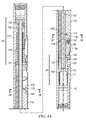
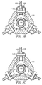
FIGURES 3A ,3B, and 3C (collectivelyFIGURE 3 ) depict longitudinal and circular cross sectional views of the downhole tool depicted onFIGURE 2A in which the cutting block and milling blade are in retracted positions. -
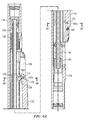
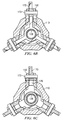
FIGURES 4A ,4B, and 4C (collectivelyFIGURE 4 ) depict longitudinal and circular cross sectional views of the downhole tool depicted onFIGURE 2A in which the cutting block is partially extended and the milling blade is retracted or substantially retracted in the cutting block. -
FIGURES 5A ,5B, and 5C (collectivelyFIGURE 5 ) depict longitudinal and circular cross sectional views of the downhole tool depicted onFIGURE 2A in which both the cutting block and the milling blade are partially extended. -
FIGURES 6A ,6B, and 6C (collectivelyFIGURE 6 ) depict longitudinal and circular cross sectional views of the downhole tool depicted onFIGURE 2A in which both the cutting block and the milling blade are in extended positions. -
FIGURE 7 depicts a flow chart of one exemplary method in accordance with the present disclosure. -
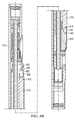
FIGURE 8A depicts a longitudinal cross-sectional view of a portion of a downhole tool embodiment of the present disclosure having alternative cutting block and milling blade configurations in which both the cutting block and the milling blade are in retracted positions. -
FIGURE 8B depicts a longitudinal cross-sectional view of the downhole tool embodiment shown onFIGURE 8A in which the cutting block is partially extended and the milling blade is retracted or substantially retracted in the cutting block. -
FIGURE 8C depicts a longitudinal cross-sectional view of the downhole tool embodiment shown onFIGURE 8A in which both the cutting block and the milling blade are partially extended. -
FIGURE 8D depicts a longitudinal cross-sectional view of the downhole tool embodiment shown onFIGURE 8A in which both the cutting block and the milling blade are in extended positions. - With respect to
FIGURES 1 through 8D , it will be understood that features or aspects of the one or more embodiments illustrated may be shown from various views. Where such features or aspects are common to particular views, they are labeled using the same reference numeral. Thus, a feature or aspect labeled with a particular reference numeral on one view inFIGURES 1 through 8D may be described herein with respect to that reference numeral shown on other views. -
FIGURE 1 depicts one exemplary embodiment of a downhole tool 100 (i.e., a casing section mill or a dual string section mill) deployed in a casedwellbore 40. InFIGURE 1 , arig 20 is positioned in the vicinity of a subterranean oil or gas formation. Therig 20 may include, for example, a derrick and a hoisting apparatus for lowering and raising various components into and out of thewellbore 40. Thewellbore 40 is at least partially cased with a string ofmetallic liners 50. Atool string 80 including adownhole tool 100, configured in accordance with the present disclosure, is depicted as being run into the wellbore.Downhole tool 100 includes at least one cutting block and milling blade combination (not shown) that is configured for milling thecasing string 50. It will be understood thattool string 80 may include other suitable components and other downhole tools as needed for a particular downhole operation and that the embodiments disclosed herein are not limited to any particular rig configuration, derrick, or hoisting apparatus. -
FIGURES 2A and 2B depict perspective and partially exploded views ofdownhole tool 100. In the exemplary embodiment depicted,downhole tool 100 includes atool body 110 including uphole and downhole threadedend portions axial recesses 115 disposed or formed in thetool body 110. The cutting blocks 150 are configured to move between radially retracted (as depicted onFIGURE 2A ) and radially extended positions as described in more detail below with respect toFIGURES 3A-6C . Amilling blade 170 is deployed in anaxial slot 152 in each of the cutting blocks 150 and biased radially inward towards the tool axis. Themilling blades 170 are also configured to move between radially retracted (as depicted onFIGURE 2A ) and radially extended positions (FIGURE 2B ). In the foregoing disclosure,downhole tool 100 is described in more detail with respect to a single cutting block and milling blade. It will be understood by those skilled in the art that tools in accordance with the present disclosure preferably, although not necessarily, include multiple cutting blocks and milling blades. - Cutting
block 150 includes a plurality ofangled splines 154 formed on the lateral sides thereof. Thesplines 154 are sized and shaped to engage correspondingangled splines 118 formed on the lateral sides of theaxial recess 115. Interconnection betweensplines 154 andsplines 118 advantageously increases the contact surface area between the cuttingblock 150 and thetool body 110, thereby providing a more robust structure suitable for downhole casing milling and/or cement removal operations. Thesplines splines downhole tool 100. As such, relative axial motion between the cuttingblock 150 and thetool body 110 causes a corresponding radial extension or retraction of theblock 150. Thesplines block 150 is radially extended via uphole axial motion of theblock 150 with respect to thetool body 110. Thesplines - In the exemplary embodiment depicted, at least a
nose portion 155 of thecutting block 150 is fitted with a plurality of cuttingelements 157. In one or more other embodiments, the entire radially facing outer surface (also referred to in the art as the gage surface) of thecutting block 150 may be fitted with cuttingelements 157. The embodiments of the present disclosure are not limited with respect to the placement or quantity of cutting elements. Moreover, any cutting elements suitable for milling/removing cement may be utilized including, but not limited to, polycrystalline diamond cutter (PDC) inserts, thermally stabilized polycrystalline (TSP) inserts, diamond inserts, boron nitride inserts, abrasive materials, and other cutting elements known to those skilled in the art. The cuttingblock 150 may further include various wear protection measures deployed thereon, for example, including the use of wear buttons, hard facing materials, or various other wear resistant coatings. The embodiments of the present disclosure are not limited with respect to the quantity, placement or type of wear protection measures or devices deployed thereon. -
Milling blade 170 is deployed in a correspondingaxial slot 152 disposed or formed in thecutting block 150. Theblade 170 is secured to thecutting block 150 via first and second axially spacedpins 172, 173 (in the exemplary embodiment depicted, thepins FIGURES 2C and 2D , thepins slots cutting block 150. Theslots cutting block 150 beyond a predetermined axial location causes a stepwise extension of the milling blade 170 (as described in more detail below). In the exemplary embodiment depicted onFIGURE 2C , thesecond pin 173 engages acurved slot 163 having afirst end portion 163a that faces (or points or is directed) in the uphole direction and asecond end portion 163b that faces (or points or is directed) radially outward. Now turning toFIGURE 2D , thefirst pin 172 engages an angled slot 162 (i.e., neither parallel nor perpendicular to the longitudinal axis through tool 100) having radially inner andouter end portions Slot 162 may be substantially perpendicular to thesplines 154, for example, as in the depicted embodiment ofFIGURE 2D (although the disclosed embodiments are not limited in this regard). The angle ofslot 162 may be selected so as to predetermine the deployment rate ofmilling blade 170. A steeper-angledslot 162 causes a more rapid deployment but decreases the necessary wedging action when theblade 170 is extended. Thus, there may be a trade off in selecting the angle between achieving a suitable deployment rate and a sufficient wedging action. A curved slot 162 (not shown) may also be utilized such that the rate of deployment is variable and depends on the degree of deployment (e.g., such that the rate increases with increasing deployment). Again, the embodiments disclosed herein are not limited in these regards. - Those skilled in the art will readily appreciate that the cutting and/or milling surfaces of
milling blade 170 may be dressed using any known cutting or other materials in the art. For example, these surfaces may be substantially or heavily hard faced with a metallurgically-applied tungsten carbide material. Other surface treatments may include, for example, disposition of a diamond or cubic boron nitride material, disposition of an embedded natural or polycrystalline diamond, and/or the like. Other suitable surface treatments may be equally employed. - As illustrated on
FIGURE 3A-C , millingblade 170 is spring biased in the retracted position. Turning now toFIGURE 3A , acompression spring 167 is deployed between aninternal surface 159 of thecutting block 150 and awing 179 of themilling blade 170. Thespring 167 is angled with respect to the tool axis and therefore biases theblade 170 radially inward and axially uphole with respect to thecutting block 150 such thatpin 172 is biased towardsend portion 162a ofslot 162 andpin 173 is biased towardsend portion 163a ofslot 163. - Extension and retraction of the one or more cutting blocks 150 and the one or
more milling blades 170 is now described in more detail with respect toFIGURES 3 through 6 .FIGURE 3A depicts a longitudinal cross sectional view of downhole tool 100 (i.e., milling tool 100) with cuttingblock 150 andmilling blade 170 in a retracted, or substantially retracted, position (whileFIGURES 3B and 3C depict circular cross sections ofdownhole tool 100 throughpins block 150 is deployed axially betweenspring biasing mechanism 130 andhydraulic actuation mechanism 140 that are also deployed in thetool body 110. In the exemplary embodiment depicted, an internal orinner mandrel 120 is deployed in thetool body 110 at a position internal to thespring mechanism 130, thehydraulic mechanism 140, and thecutting block 150. Themandrel 120 includes acentral throughbore 122, thereby providing a channel for the flow of drilling fluid/mud through thedownhole tool 100. Thespring biasing mechanism 130 includes acompression spring 132 deployed about themandrel 120 and axially between anupper cap 133 and astop ring 135. Theupper cap 133 is rigidly connected with thetool body 110 such that thecompression spring 132 is configured to bias thecutting block 150 in the downhole direction. The bias ofcompression spring 132 also urges thecutting block 150 radially inward (due to the configuration of theangled splines 118, 154). -
Hydraulic actuation mechanism 140 is configured to urge thecutting block 150 in the uphole direction against the spring bias when differential fluid pressure is applied to thebore 122 of themilling tool 100. Anaxial piston 142 is sealingly engaged with aninner surface 111 of thetool body 110 and anouter surface 123 of themandrel 120. Drilling fluid pressure acts on anaxial face 143 of thepiston 142, thereby urging it in the uphole direction. Thepiston 142 engagesdrive ring 145 andretainer 146 which in turn engage cutting block 150 such that translation of thepiston 142 causes a corresponding translation and extension of thecutting block 150. - Hydraulic actuation of the
cutting block 150 andmilling blade 170 may be initiated using substantially any means known in the art. For example, a conventional ball seat (not shown) may be deployed in the tool string 80 (FIGURE 1 ) below the milling tool. As is known to those skilled in the art, a ball may be dropped from the surface onto the ball seat. The ball provides an obstruction to the flow of drilling fluid through thetool string 80 which causes an increase in the fluid pressure in thedownhole tool 100. The pressure increase urgespiston 142 uphole against the spring bias, thereby actuating thecutting block 150 andmilling blade 170 as described above and in more detail below. Upon completion of the casing milling and/or cement removal operation (or at any other desirable time), the fluid pressure in thedownhole tool 100 may be increased above some predetermined threshold so as to shear (release) the ball seat and retract thecutting block 150 and milling blade 170 (via spring force provided by compression spring 132). The cuttingblock 150 andmilling blade 170 may also be retracted by reducing the fluid pressure below a predetermined threshold. It will be understood that the embodiments disclosed herein are in no way limited to the use of a ball seat. Substantially any other actuation means may be utilized, for example, including but not limited to the deployment of a flow nozzle in the lower end portion of thetool body 110. - In one or more embodiments in accordance with the present disclosure, the cutting
block 150 andmilling blade 170 extend radially outward relative to the central axis of thetool body 110 to extended positions in at least first and second stages. In a first stage, the cuttingblock 150 extends radially outward relative to the central axis of thetool body 110 towards a first cutting block extended position while themilling blade 170 remains retracted or at least substantially retracted in thecutting block 150, and in a second stage, both thecutting block 150 andmilling blade 170 simultaneously extend radially outward relative to the central axis of thetool body 110 until both are extended or at least substantially extended (i.e., the cuttingblock 150 is in a second cutting block extended position andmilling blade 170 is in a milling blade extended position). - In the exemplary embodiment depicted on
FIGURES 3-6 , the cuttingblock 150 andmilling blade 170 extend radially outward relative to the central axis of thetool body 110 to extended positions in first, second and third stages. In the first stage, the cuttingblock 150 extends radially outward relative to the central axis of thetool body 110 towards a first cutting block extended position while themilling blade 170 remains retracted or at least substantially retracted in thecutting block 150. In the second stage, cuttingblock 150 continues to extend radially outward relative to the central axis of thetool body 110 towards a second cutting block extended position while one axial end portion of themilling blade 170 pivots outward beyond the outer surface of thecutting block 150 to a first milling blade extended position. In the third stage, cuttingblock 150 continues to extend radially outward relative to the central axis of thetool body 110 to a third cutting block extended position while the other axial end portion of themilling blade 170 extends radially outward beyond the outer surface of thecutting block 150 to a second milling blade extended position. The cuttingblock 150 andmilling blade 170 are extended or at least substantially extended at the end of the third stage. These stages are now described in more detail below with respect toFIGURES 4 ,5 , and6 . -
FIGURES 4A ,4B, and 4C depict longitudinal and circular cross sectional views of themilling tool 100 at the end of the first stage. In the first stage, fluid pressure urgespiston 142, and therefore cuttingblock 150, in the uphole direction against the bias ofcompression spring 132. The engagement of theangled splines cutting block 150 to extend radially outward as it translates in the uphole direction.Milling blade 170 remains biased in a retracted or at least substantially retracted position in thecutting block 150 withpin 172 engaginginner end portion 162a of theangled slot 162 and pin 173engaging end portion 163a ofslot 163. At the end of the first stage (as depicted onFIGURE 4A ), anuphole end portion 178 of themilling blade 170 contacts aradially extending fin 126 ofstop ring 125. Thestop ring 125 is deployed about and axially secured with themandrel 120 such that it does not translate with thecutting block 150 andmilling blade 170 during hydraulic actuation ofpiston 142. -
FIGURES 5A ,5B, and 5C depict longitudinal and circular cross sectional views of themilling tool 100 at the end of the second stage. In the second stage, the cuttingblock 150 continues to translate uphole and radially outward as drilling fluid/mud pressure urgespiston 142 in the uphole direction. Themilling blade 170 abuts stop ring/member 125 (at fin 126) and is thereby restricted from further translation in the uphole direction. The abutment of themilling blade 170 with the stop ring/member 125 urges themilling blade 170 against its spring bias (via spring 167) as thecutting block 150 continues to translate uphole past themilling blade 170. This in turn causespin 173 to slide away fromend portion 163a towards the center (elbow) ofslot 163 and pin 172 to slide away frominner end portion 162a towardsouter end portion 162b ofangled slot 162. The relative axial motion of thecutting block 150 with respect to themilling blade 170 and the engagement ofpins corresponding slots milling blade 170 to pivot such that adownhole end portion 176 of theblade 170 extends radially outward while anuphole end portion 178 of theblade 170 remains retracted radially inward with respect to thecutting block 150. At the end of the second stage (as depicted onFIGURE 5A-C ),pin 173 is located at the center (the elbow) ofslot 163 andpin 172 is located at theouter end portion 162b ofangled slot 162. In this configuration, thedownhole end portion 176 of theblade 170 is extended or at least substantially extended with respect to thecutting block 150, for example, such that cuttingsurface 171 contacts or penetrates a wellbore casing string (not shown), e.g., to make a circumferential cut therein. Theuphole end portion 178 of theblade 170 remains retracted or at least substantially retracted in thecutting block 150. -
FIGURES 6A ,6B, and 6C depict longitudinal and circular cross sectional views of themilling tool 100 at the end of the third stage at which thecutting block 150 andmilling blade 170 are extended or at least substantially extended. In the third stage, the cuttingblock 150 continues to translate uphole and radially outward as drilling fluid/mud pressure urgespiston 142 in the uphole direction. Meanwhile,milling blade 170 again translates axially uphole and radially outward with thecutting block 150 as theuphole end portion 178 of theblade 170 slides up (and along) aramp 128 on thefin portion 126 ofstop ring 125.Pin 173 slides towardsend portion 163b of slot 163 (radially outward from the elbow portion of the slot 163). At the end of the third stage (as depicted onFIGURE 6A-C ),pin 173 is located inend portion 163b ofslot 163 while theuphole end portion 178 of themilling blade 170 is radially supported byfin 126. Thedownhole end portion 176 of theblade 170 is supported by the wedging action between thepin 172 andangled slot 162. In this configuration, cuttingblock 150 andmilling blade 170 are extended or at least substantially extended with respect to thetool body 110.Compression spring 132 may be selected such that it is substantially fully compressed when thecutting block 150 is extended or substantially extended. Likewise,spring 167 may be similarly selected such that it is substantially fully compressed when themilling blade 170 is extended or substantially extended. The embodiments of the present disclosure are, of course, not limited in these regards. - With further reference now to
FIGURES 6B and 6C , it will be understood that thecutting block 150 advantageously provides circumferential support for themilling blade 170 when extended or substantially extended. Themilling blade 170 may be thought of as telescoping radially outward from theblock 150. Extension of thecutting block 150 outward from thetool body 110 reduces the required extension of the milling blade and thereby reduces milling loads on themilling blade 170. Notwithstanding, support provided by theblocks 150 tends to advantageously minimize structural damage to theblades 170 during casing milling and/or cement removal operations. - While not limited in this regard,
milling tool 100 is particularly well-suited for dual string section milling operations.FIGURE 7 depicts a flow chart of oneexemplary method embodiment 200 for a dual string section milling operation. Theexemplary method embodiment 200 depicted includes milling a length of a dual string wellbore including removing the inner and outer casing strings and an annular cement layer located between the strings. In the exemplary embodiment depicted, the inner casing string is first milled at 202, e.g., using a conventional milling tool. After removal of the inner string,milling tool 100 is used to simultaneously remove the annular cement layer and mill the outer casing string insteps 204 through 212.Milling tool 100 is first positioned at a start location/position at 204. The starting location can be the uphole end portion of the borehole section to be milled. The cutting blocks 150 andmilling blades 170 are retracted or substantially retracted (as depicted inFIGURE 3 ) while the tool is positioned at 204. - With continued reference to
FIGURE 7 , actuation ofmilling tool 100 is initiated at 206. The cutting blocks 150 are extended into contact with the annular cement layer while the tool rotates in the borehole. As the cement layer is removed, the cutting blocks 150 continue to extend radially (while themilling blades 170 remain at least partially retracted as depicted onFIGURE 4 ). After the cement layer has been partially or substantially fully removed at the start location, themilling blades 170 begin to pivot radially outward (as depicted onFIGURE 5 ) such that the cuttingsurface 171 makes an initial cut in the outer casing string at 208. The outer casing is then substantially fully removed at the starting location at 210 as themilling blades 170 are further extended (as depicted onFIGURE 6 ). After removal of the cement layer and the outer casing string at the starting location, the tool string is then urged downhole (while rotating and with the cutting blocks 150 andmilling blades 170 extended) so as to simultaneously remove the cement layer and the mill outer casing string at 212. During the milling operation, thenose portion 155 of thecutting block 150 leads themilling blade 170 downhole (i.e., thenose portion 155 of thecutting block 150 is located downhole of the milling blade 170). Such deployment advantageously provides for dual milling functionality in which thecutting block 150 removes the cement layer while themilling blade 170 simultaneously mills the casing string. This deployment also tends to minimize the loading onmilling blade 170 asblade 170 is not generally required to simultaneously remove or mill both cement and casing. -
FIGURES 8A-D depict longitudinal cross-sectional views of another milling tool embodiment 300 in accordance with the present disclosure. The exemplary embodiment depicted is similar to thedownhole tool embodiment 100 described above with respect toFIGURES 2 through 6 with the exception that the downhole tool embodiment 300 ofFIGURES 8A-D includesalternative cutting block 350 andmilling blade 370 configurations.FIGURE 8A depicts a cross-sectional view of milling tool 300 when thecutting block 350 andmilling blade 370 are in a collapsed or substantially collapsed position. Milling tool 300 is similar tomilling tool 100 in that thecutting block 350 andmilling blade 370 extend radially outward in first, second, and third stages. In the first stage, the cuttingblock 350 extends outward while themilling blade 370 remains retracted or at least substantially retracted in thecutting block 350.FIGURE 8B depicts the milling tool 300 at the end of the first stage. In the second stage, cuttingblock 350 continues to extend outward while one axial end portion of themilling blade 370 pivots outward beyond the outer surface of thecutting block 350.FIGURE 8C depicts the milling tool 300 at the end of the second stage. In the third stage, cuttingblock 350 continues to extend outward while the other axial end portion of themilling blade 370 extends outward beyond the outer surface of thecutting block 350. The cuttingblock 150 andmilling blade 170 are extended or at least substantially extended at the end of the third stage as depicted onFIGURE 8D . - Cutting
block 350 is similar to cutting block 150 in that it includes a plurality of angled splines (not shown) formed on the lateral sides thereof. Cuttingblock 350 further includes a plurality of cuttingelements 357 formed on anose portion 355 thereof. The cutting elements may be further deployed on the entire gage surface of thecutting block 350 as described in more detail above.Milling blade 370 is deployed in a correspondingaxial slot 352 disposed or formed in thecutting block 350 as described above with respect to millingtool 100. Anuphole end portion 378 of theblade 370 is coupled to thecutting block 350 viahinge arm 360. As depicted, theblade 370 is pinned to thehinge arm 360 viapin 372 which is in turn pinned to thetool body 310 viapin 362.Pin 362 extends through anangled slot 363 in thecutting block 350 as described in more detail below. -
FIGURE 8B depicts the milling tool 300 at the end of the first stage. In the first stage, fluid pressure urges the piston, and therefore thecutting block 350, in the uphole direction against the spring bias. The engagement of the angled splines causes thecutting block 350 to extend radially outward as it translates in the uphole direction as described above.Milling blade 370 remains substantially axially stationary with respect to thetool body 310 and is optionally biased in a retracted or substantially retracted position in thecutting block 350. Cuttingblock 350 includes anangled slot 363 oriented in the same direction as the angled splines and therefore slidespast pin 362 inhinge arm 360 as it translates uphole (and radially outward). At the end of the first stage (as depicted onFIGURE 8B ), adownhole end portion 376 of themilling blade 370 begins to contact aramp 353 at the downhole end portion ofslot 352. -
FIGURE 8C depicts the milling tool 300 at the end of the second stage. In the second stage, the cuttingblock 150 continues to translate uphole and radially outward as drilling fluid/mud pressure urges the piston in the uphole direction. Themilling blade 370 continues to remain substantially axially stationary with respect to thetool body 310 as thedownhole end portion 376 of theblade 370 slides up theramp 353. The relative axial motion of thecutting block 350 with respect to themilling blade 370 and the engagement of theblade 370 with theramp 353 causes themilling blade 370 to pivot aboutpin 372 inhinge arm 360 such that thedownhole end portion 376 of theblade 370 extends radially outward while theuphole end portion 378 of theblade 370 remains retracted radially inward with respect to thecutting block 350. At the end of the second stage (as depicted onFIGURE 8C ), thedownhole end portion 376 of theblade 370 is at the upper end portion of theramp 353 and engagesnotch 354 in thecutting block 350. In this configuration, thedownhole end portion 376 of theblade 370 is extended with respect to thecutting block 350, for example, such that cuttingsurface 371 contacts or penetrates a wellbore casing string (not shown). Theuphole end portion 378 of theblade 370 remains retracted or at least substantially retracted in thecutting block 350. -
FIGURE 8D depicts the milling tool 300 at the end of the third stage at which thecutting block 350 andmilling blade 370 are extended or at least substantially extended. In the third stage, the cuttingblock 350 continues to translate uphole and radially outward as drilling fluid/mud pressure urges the piston in the uphole direction. Themilling blade 370 also translates axially uphole and radially outward with thecutting block 350 as thedownhole end portion 376 of theblade 370 engages thenotch 354. Such engagement and translation of themilling blade 370 causes theuphole end portion 378 of theblade 370 to pivot radially outward onhinge arm 360. At the end of the third stage (as depicted onFIGURE 8D ), theblade 370 is wedged radially outward.Pin 362 is located at a radially inner and downhole end portion ofslot 363 whilehinge arm 360 radially supports theuphole end portion 378 of theblade 370. Thedownhole end portion 376 of theblade 370 is wedged intonotch 354. In this configuration, cuttingblock 350 andmilling blade 370 are extended or at least substantially extended with respect to thetool body 310. - It will be understood by those skilled in the art, that in the milling tool embodiment 300, the cutting
block 350 andmilling blade 370 are advantageously back drivable. By back drivable, it is meant that an uphole force acting on thetool body 310 causes theblade 370 to pivot radially inward as it engages the borehole wall or a narrower section of casing string. Such back drivability advantageously tends to prevent the milling tool 300 from becoming lodged in the wellbore should the cuttingblock 350 andmilling blade 370 retraction mechanism fail in service. - Although only a few example embodiments have been described in detail above, those skilled in the art will readily appreciate that many modifications are possible in the example embodiments without materially departing from the dual string section mill. Accordingly, all such modifications are intended to be included within the scope of this disclosure.
Claims (18)
- A milling tool (100, 300) comprising:a tool body (110, 310) having a central axis therethrough, the tool body (110, 310) including an axial recess (115) and the tool body (110, 310) being configured to couple with a tool string (80); and at least one milling blade (170, 370),characterized in that;the milling tool (100, 300) includes:at least one cutting block (150, 350) deployed in the axial recess (115), the cutting block (150, 350) arranged and designed to extend radially outward relative to the central axis of the tool body (110, 310) to a cutting block extended position and retract radially inward from the cutting block extended position towards the central axis of the tool body (110, 310); andthe at least one milling blade (170, 370) is deployed in an axial slot (152, 352) disposed in the cutting block (150, 350), the milling blade (170, 370) arranged and designed to extend radially outward from the cutting block (150, 350) to a milling blade extended position and retract radially inward from the milling blade extended position towards the cutting block (150, 350).
- The milling tool (100, 300) of claim 1, wherein the at least one cutting block (150, 350) and the at least one milling blade (170, 370) are arranged and designed to extend radially outward in first and second stages, the first stage includes the cutting block (150, 350) extending radially outward relative to the central axis of the tool body (110, 310) towards a first cutting block extended position while the milling blade (170, 370) remains at least substantially retracted in the cutting block (150, 350) and the second stage includes the cutting block (150, 350) extending outward relative to the central axis of the tool body (110, 310) to a second cutting block extended position while the milling blade (170, 370) simultaneously extends outward from the cutting block (150, 350) to the milling blade extended position.
- The milling tool (100, 300) of claim 1 or 2, wherein the at least one cutting block (150, 350) and the at least one milling blade (170, 370) are arranged and designed to extend radially outward in first, second, and third stages, the first stage includes the cutting block (150, 350) extending radially outward relative to the central axis of the tool body (110, 310) towards a first cutting block extended position while the milling blade (170, 370) remains at least substantially retracted in the cutting block (150, 350), the second stage includes the cutting block (150, 350) extending radially outward relative to the central axis of the tool body (110, 310) towards a second cutting block extended position while a first axial end portion of the milling blade (170, 370) pivots radially outward from the cutting block (150, 350) to a first mill blade extended position, and the third stage includes the cutting block (150, 350) extending radially outward relative to the central axis of the tool body (110, 310) to a third cutting block extended position while a second opposing axial end portion of the milling blade (170, 370) extends radially outward from the cutting block (150, 350) to a second mill blade extended position.
- The milling tool (100, 300) of any one of the preceding claims, wherein the at least one cutting block (150, 350) is arranged and designed to provide lateral support for the at least one milling blade (170, 370) when the at least one milling blade (170, 370) is extended radially outward from the cutting block (150, 350).
- The milling tool (100, 300) of any one of the preceding claims, further comprising a plurality of cutting structures (157, 357) deployed on the at least one cutting block (150, 350), the cutting structures (157, 357) being arranged and designed to remove a cement layer.
- The milling tool (100, 300) of any one of the preceding claims, wherein the at least one milling blade (170, 370) is sized and shaped to mill a wellbore casing string (50).
- The milling tool (100, 300) of any one of the preceding claims, wherein at least three cutting blocks (150, 350) are circumferentially-spaced around the tool body (110, 310) and deployed in corresponding circumferentially-spaced recesses (115) disposed in the tool body (110, 310), each of the at least three cutting blocks (150, 350) including a corresponding milling blade (170, 370) deployed in an axial slot (152, 352) disposed in each cutting block (150, 350).
- The milling tool (100, 300) of claim 1, further comprising:a spring (130) deployed in the tool body (110, 310), the spring (130) biasing the at least one cutting block (150, 350) in a first axial direction, the spring (130) also biasing the at least one cutting block (150, 350) radially inward towards the tool body (110, 310); anda piston (142) deployed in the tool body (110, 310), the piston (142) configured to urge the at least one cutting block (150, 350) in a second axial direction against the bias of the spring (130), the piston (142) being responsive to a differential hydraulic pressure in the tool body (110, 310).
- The milling tool (100, 300) of any one of the preceding claims, wherein the at least one cutting block (150, 350) comprises a plurality of angled splines (154) disposed on lateral sides thereof, the angled splines (154) engaging corresponding angled splines (118) disposed in the recess (115) of the tool body (110, 310), the angled splines (154) and corresponding angled splines (118) being angled with respect to the central axis of the tool body (110, 310) such that translation of the at least one cutting block (150, 350) in the second axial direction extends the at least one cutting block (150, 350) radially outward relative to the central axis of the tool body (110, 310).
- The milling tool (100) of any one of the preceding claims, wherein the at least one milling blade (170) is coupled to the at least one cutting block (150) via first (172) and second (173) axially-spaced pins, the first pin (172) engaging an angled slot (162) disposed in the at least one cutting block (150) and the second pin (173) engaging a curved slot (163) disposed in the cutting block (150).
- The milling tool (100) of any one of the preceding claims, wherein the at least one milling blade (170) is spring biased in a radially inward direction toward the cutting block (150), and in a second axial direction with respect to the at least one cutting block (150).
- The milling tool (100, 300) of any one of the preceding claims, wherein a first axial end portion (176, 376) of the at least one milling blade (170, 370) includes a cutting surface (171, 371)) formed on a radially outer surface thereof, the cutting surface (171, 371) being configured for making a circumferential cut in a wellbore casing string (50).
- The milling tool (100, 300) of any one of the preceding claims, further comprising an inner mandrel (120) having a throughbore (122) configured for transporting fluid through the tool body (110, 310), a piston (142) in the tool body (110, 310) being deployed about and in sealingly engagement with a first axial end portion of the inner mandrel (120) and a spring (132) being deployed about a second opposing axial end portion of the inner mandrel (120).
- The milling tool (300) of any one of the preceding claims, further comprising a hinge arm (360) pinned to the tool body (310) and to a second axial end portion of the at least one milling blade (370).
- The milling tool (300) of claim 14, wherein the hinge arm (360) is pinned to the tool body (310) through an angled slot (363) in the at least one cutting block (350).
- A method for substantially simultaneously removing a cement layer and milling a casing string (50) in a wellbore (40), the method comprising:rotating a milling tool (100, 300) at a starting downhole position in a wellbore (40), the milling tool (100, 300) including a cutting block (150, 350) deployed in a tool body (110, 310) and a milling blade (170, 370) deployed in the cutting block (150, 350), the cutting block (150, 350) arranged and designed to extend radially outward from a central axis of the tool body (110, 310) and the milling blade (170, 370) arranged and designed to extend radially outward from the cutting block (150, 350);extending the cutting block (150, 350) radially outward from the central axis of the tool body (110, 310) while the milling blade (170, 370) remains at least partially retracted in the cutting block (150, 350);removing at least a portion of a cement layer on an inner surface of an outer casing string at the starting downhole position with the cutting block (150, 350) in its extended position;pivoting a first axial end portion (176, 376) of the milling blade (170, 370) radially outward from the cutting block (150, 350);cutting the outer casing string with the first axial end portion (176, 376) of the milling blade (170, 370) in its extended position;extending a second axial end portion (178, 378) of the milling blade (170, 370) radially outward from the cutting block (150, 350);removing at least a portion of the outer casing string at the starting downhole position with the second axial end portion (178, 378) of the milling blade (170, 370) in its extended position; andurging the milling tool (100, 300) in a downhole direction while the cutting block (150, 350) and the milling blade (170, 370) remain extended, translation of the milling tool (100, 300) in the downhole direction causing the cutting block (150, 350) and the milling blade (170, 370) to simultaneously remove cement layer and mill outer casing string.
- The method of claim 16 further comprising milling an inner casing string in a separate downhole trip prior to removing at least a portion of the cement layer on the inner surface of the outer casing string.
- The method of claim 16 or claim 17 further comprising milling the inner casing string with a conventional milling tool.
Applications Claiming Priority (2)
| Application Number | Priority Date | Filing Date | Title |
|---|---|---|---|
| US201161495724P | 2011-06-10 | 2011-06-10 | |
| PCT/US2012/041537 WO2012170806A1 (en) | 2011-06-10 | 2012-06-08 | Dual string section mill |
Publications (3)
| Publication Number | Publication Date |
|---|---|
| EP2718534A1 EP2718534A1 (en) | 2014-04-16 |
| EP2718534A4 EP2718534A4 (en) | 2015-12-02 |
| EP2718534B1 true EP2718534B1 (en) | 2016-11-02 |
Family
ID=47296470
Family Applications (1)
| Application Number | Title | Priority Date | Filing Date |
|---|---|---|---|
| EP12796606.7A Active EP2718534B1 (en) | 2011-06-10 | 2012-06-08 | Dual string section mill |
Country Status (3)
| Country | Link |
|---|---|
| US (2) | US9097073B2 (en) |
| EP (1) | EP2718534B1 (en) |
| WO (1) | WO2012170806A1 (en) |
Families Citing this family (22)
| Publication number | Priority date | Publication date | Assignee | Title |
|---|---|---|---|---|
| US9022117B2 (en) | 2010-03-15 | 2015-05-05 | Weatherford Technology Holdings, Llc | Section mill and method for abandoning a wellbore |
| EP2718534B1 (en) | 2011-06-10 | 2016-11-02 | Services Pétroliers Schlumberger | Dual string section mill |
| US8887798B2 (en) * | 2011-08-25 | 2014-11-18 | Smith International, Inc. | Hydraulic stabilizer for use with a downhole casing cutter |
| AU2013299834B2 (en) * | 2012-08-10 | 2017-09-21 | Abrado, Inc. | Well bore casing mill with expandable cutter bases |
| CA2894540A1 (en) * | 2012-12-19 | 2014-06-26 | Schlumberger Canada Limited | Downhole valve utilizing degradable material |
| US9938781B2 (en) | 2013-10-11 | 2018-04-10 | Weatherford Technology Holdings, Llc | Milling system for abandoning a wellbore |
| US9617815B2 (en) * | 2014-03-24 | 2017-04-11 | Baker Hughes Incorporated | Downhole tools with independently-operated cutters and methods of milling long sections of a casing therewith |
| US10030459B2 (en) | 2014-07-08 | 2018-07-24 | Smith International, Inc. | Thru-casing milling |
| GB2535787B (en) * | 2015-02-27 | 2017-08-16 | Schlumberger Holdings | Milling tool and method |
| GB201505620D0 (en) | 2015-04-01 | 2015-05-13 | Wardley Michael | Specification for method of abandoning a well |
| US10037836B2 (en) | 2015-04-03 | 2018-07-31 | Schlumberger Technology Corporation | Slickline manufacturing techniques |
| EP3303759B1 (en) | 2015-05-28 | 2019-09-18 | Weatherford Technology Holdings, LLC | Cutter assembly for cutting a tubular, bottom hole assembly comprising such a cutter assembly and method of cutting a tubular |
| US10081996B2 (en) * | 2015-07-09 | 2018-09-25 | Baker Hughes, A Ge Company, Llc | One trip tubular cutting and milling down tube and associated collars |
| GB2541017B (en) * | 2015-08-06 | 2018-06-06 | Schlumberger Holdings | Downhole cutting tool |
| WO2017039983A1 (en) * | 2015-08-29 | 2017-03-09 | Schlumberger Technology Corporation | Thru-casing section mill |
| WO2017053151A1 (en) * | 2015-09-15 | 2017-03-30 | Abrado, Inc. | Downhole tubular milling apparatus, especially suitable for deployment on coiled tubing |
| US10081997B2 (en) | 2015-11-18 | 2018-09-25 | Baker Hughes, A Ge Company, Llc | Watermelon mill with replaceable cutting structure |
| NO342501B1 (en) | 2016-09-29 | 2018-06-04 | Innovation Energy As | Downhole tool for removing sections of metal tubing, and modular downhole tool for insertion in a wellbore. |
| US11193345B2 (en) | 2016-09-29 | 2021-12-07 | Innovation Energy As | Downhole tool |
| US20210254422A1 (en) | 2018-06-28 | 2021-08-19 | Schlumberger Technology Corporation | Methods and apparatus for removing sections of a wellbore wall |
| GB2604322A (en) * | 2021-01-08 | 2022-09-07 | Abrado Inc | Downhole tubular milling apparatus |
| US20230109781A1 (en) * | 2021-10-12 | 2023-04-13 | Baker Hughes Oilfield Operations Llc | Casing mill, method, and system |
Family Cites Families (17)
| Publication number | Priority date | Publication date | Assignee | Title |
|---|---|---|---|---|
| SU926233A1 (en) | 1980-02-04 | 1982-05-07 | За витель и М, Н, -Р Ш, Стрелко, В. И, Тут|ев. Урумов/ .. | Deep-well pipe cutter and miller |
| US5373900A (en) | 1988-04-15 | 1994-12-20 | Baker Hughes Incorporated | Downhole milling tool |
| US4938291A (en) * | 1986-01-06 | 1990-07-03 | Lynde Gerald D | Cutting tool for cutting well casing |
| US5014780A (en) | 1990-05-03 | 1991-05-14 | Uvon Skipper | Long distance section mill for pipe in a borehole |
| US5074355A (en) | 1990-08-10 | 1991-12-24 | Masx Energy Services Group, Inc. | Section mill with multiple cutting blades |
| US6125929A (en) | 1998-06-01 | 2000-10-03 | Baker Hughes Incorporated | Casing cutter blade support sleeve |
| US6920923B1 (en) | 2003-09-22 | 2005-07-26 | Alejandro Pietrobelli | Section mill for wells |
| WO2005124094A1 (en) | 2004-06-09 | 2005-12-29 | Halliburton Energy Services N.V. | Enlarging and stabilising tool for a borehole |
| RU56931U1 (en) | 2006-05-05 | 2006-09-27 | Закрытое акционерное общество "Октопус" | DEVICE FOR CUTTING A PART OF A PIPE COLUMN IN A WELL |
| WO2008024791A2 (en) | 2006-08-21 | 2008-02-28 | Weatherford/Lamb, Inc. | Releasing and recovering tool |
| EP2304159B1 (en) | 2008-05-05 | 2014-12-10 | Weatherford/Lamb, Inc. | Signal operated tools for milling, drilling, and/or fishing operations |
| US8540035B2 (en) | 2008-05-05 | 2013-09-24 | Weatherford/Lamb, Inc. | Extendable cutting tools for use in a wellbore |
| US7823632B2 (en) | 2008-06-14 | 2010-11-02 | Completion Technologies, Inc. | Method and apparatus for programmable robotic rotary mill cutting of multiple nested tubulars |
| AU2009313207B2 (en) | 2008-11-10 | 2013-03-21 | Weatherford Technology Holdings, Llc | Extendable cutting tools for use in a wellbore |
| US9022117B2 (en) * | 2010-03-15 | 2015-05-05 | Weatherford Technology Holdings, Llc | Section mill and method for abandoning a wellbore |
| US8555955B2 (en) | 2010-12-21 | 2013-10-15 | Baker Hughes Incorporated | One trip multiple string section milling of subterranean tubulars |
| EP2718534B1 (en) | 2011-06-10 | 2016-11-02 | Services Pétroliers Schlumberger | Dual string section mill |
-
2012
- 2012-06-08 EP EP12796606.7A patent/EP2718534B1/en active Active
- 2012-06-08 US US13/492,016 patent/US9097073B2/en active Active
- 2012-06-08 WO PCT/US2012/041537 patent/WO2012170806A1/en not_active Ceased
-
2015
- 2015-06-26 US US14/751,209 patent/US10000986B2/en active Active
Non-Patent Citations (1)
| Title |
|---|
| None * |
Also Published As
| Publication number | Publication date |
|---|---|
| EP2718534A1 (en) | 2014-04-16 |
| US10000986B2 (en) | 2018-06-19 |
| US20150292289A1 (en) | 2015-10-15 |
| US9097073B2 (en) | 2015-08-04 |
| US20120325480A1 (en) | 2012-12-27 |
| EP2718534A4 (en) | 2015-12-02 |
| WO2012170806A1 (en) | 2012-12-13 |
Similar Documents
| Publication | Publication Date | Title |
|---|---|---|
| US9097073B2 (en) | Dual string section mill | |
| US10202814B2 (en) | Downhole tool with expandable stabilizer and underreamer | |
| US10047582B2 (en) | Extended duration section mill and methods of use | |
| US9725977B2 (en) | Retractable cutting and pulling tool with uphole milling capability | |
| US10815745B2 (en) | Thru-casing section mill | |
| CN111502582A (en) | Cutting inserts for initiating cuts | |
| AU2022206750B2 (en) | Tubular Cutting Tool | |
| WO2015167788A1 (en) | Cutting structure with blade having multiple cutting edges | |
| EP2673453A2 (en) | Tools for use in subterranean boreholes having expandable members and related methods | |
| US10526848B2 (en) | Cutting structure of a downhole cutting tool | |
| WO2015191529A1 (en) | Systems and methods for activating a downhole tool | |
| US20160010413A1 (en) | Thru-casing milling | |
| EP4048856B1 (en) | Milling tool | |
| EP4295012B1 (en) | Milling tool |
Legal Events
| Date | Code | Title | Description |
|---|---|---|---|
| PUAI | Public reference made under article 153(3) epc to a published international application that has entered the european phase |
Free format text: ORIGINAL CODE: 0009012 |
|
| 17P | Request for examination filed |
Effective date: 20131205 |
|
| AK | Designated contracting states |
Kind code of ref document: A1 Designated state(s): AL AT BE BG CH CY CZ DE DK EE ES FI FR GB GR HR HU IE IS IT LI LT LU LV MC MK MT NL NO PL PT RO RS SE SI SK SM TR |
|
| DAX | Request for extension of the european patent (deleted) | ||
| RA4 | Supplementary search report drawn up and despatched (corrected) |
Effective date: 20151030 |
|
| RIC1 | Information provided on ipc code assigned before grant |
Ipc: E21B 10/32 20060101ALI20151026BHEP Ipc: E21B 29/00 20060101AFI20151026BHEP |
|
| 17Q | First examination report despatched |
Effective date: 20151124 |
|
| GRAP | Despatch of communication of intention to grant a patent |
Free format text: ORIGINAL CODE: EPIDOSNIGR1 |
|
| GRAS | Grant fee paid |
Free format text: ORIGINAL CODE: EPIDOSNIGR3 |
|
| INTG | Intention to grant announced |
Effective date: 20160831 |
|
| GRAA | (expected) grant |
Free format text: ORIGINAL CODE: 0009210 |
|
| AK | Designated contracting states |
Kind code of ref document: B1 Designated state(s): AL AT BE BG CH CY CZ DE DK EE ES FI FR GB GR HR HU IE IS IT LI LT LU LV MC MK MT NL NO PL PT RO RS SE SI SK SM TR |
|
| REG | Reference to a national code |
Ref country code: GB Ref legal event code: FG4D |
|
| REG | Reference to a national code |
Ref country code: AT Ref legal event code: REF Ref document number: 842056 Country of ref document: AT Kind code of ref document: T Effective date: 20161115 Ref country code: CH Ref legal event code: EP |
|
| REG | Reference to a national code |
Ref country code: IE Ref legal event code: FG4D |
|
| REG | Reference to a national code |
Ref country code: DE Ref legal event code: R096 Ref document number: 602012024933 Country of ref document: DE |
|
| PG25 | Lapsed in a contracting state [announced via postgrant information from national office to epo] |
Ref country code: LV Free format text: LAPSE BECAUSE OF FAILURE TO SUBMIT A TRANSLATION OF THE DESCRIPTION OR TO PAY THE FEE WITHIN THE PRESCRIBED TIME-LIMIT Effective date: 20161102 |
|
| REG | Reference to a national code |
Ref country code: NL Ref legal event code: MP Effective date: 20161102 |
|
| REG | Reference to a national code |
Ref country code: LT Ref legal event code: MG4D |
|
| REG | Reference to a national code |
Ref country code: AT Ref legal event code: MK05 Ref document number: 842056 Country of ref document: AT Kind code of ref document: T Effective date: 20161102 |
|
| REG | Reference to a national code |
Ref country code: NO Ref legal event code: T2 Effective date: 20161102 |
|
| PG25 | Lapsed in a contracting state [announced via postgrant information from national office to epo] |
Ref country code: GR Free format text: LAPSE BECAUSE OF FAILURE TO SUBMIT A TRANSLATION OF THE DESCRIPTION OR TO PAY THE FEE WITHIN THE PRESCRIBED TIME-LIMIT Effective date: 20170203 Ref country code: LT Free format text: LAPSE BECAUSE OF FAILURE TO SUBMIT A TRANSLATION OF THE DESCRIPTION OR TO PAY THE FEE WITHIN THE PRESCRIBED TIME-LIMIT Effective date: 20161102 Ref country code: NL Free format text: LAPSE BECAUSE OF FAILURE TO SUBMIT A TRANSLATION OF THE DESCRIPTION OR TO PAY THE FEE WITHIN THE PRESCRIBED TIME-LIMIT Effective date: 20161102 Ref country code: SE Free format text: LAPSE BECAUSE OF FAILURE TO SUBMIT A TRANSLATION OF THE DESCRIPTION OR TO PAY THE FEE WITHIN THE PRESCRIBED TIME-LIMIT Effective date: 20161102 |
|
| PG25 | Lapsed in a contracting state [announced via postgrant information from national office to epo] |
Ref country code: PT Free format text: LAPSE BECAUSE OF FAILURE TO SUBMIT A TRANSLATION OF THE DESCRIPTION OR TO PAY THE FEE WITHIN THE PRESCRIBED TIME-LIMIT Effective date: 20170302 Ref country code: FI Free format text: LAPSE BECAUSE OF FAILURE TO SUBMIT A TRANSLATION OF THE DESCRIPTION OR TO PAY THE FEE WITHIN THE PRESCRIBED TIME-LIMIT Effective date: 20161102 Ref country code: ES Free format text: LAPSE BECAUSE OF FAILURE TO SUBMIT A TRANSLATION OF THE DESCRIPTION OR TO PAY THE FEE WITHIN THE PRESCRIBED TIME-LIMIT Effective date: 20161102 Ref country code: PL Free format text: LAPSE BECAUSE OF FAILURE TO SUBMIT A TRANSLATION OF THE DESCRIPTION OR TO PAY THE FEE WITHIN THE PRESCRIBED TIME-LIMIT Effective date: 20161102 Ref country code: IS Free format text: LAPSE BECAUSE OF FAILURE TO SUBMIT A TRANSLATION OF THE DESCRIPTION OR TO PAY THE FEE WITHIN THE PRESCRIBED TIME-LIMIT Effective date: 20170302 Ref country code: AT Free format text: LAPSE BECAUSE OF FAILURE TO SUBMIT A TRANSLATION OF THE DESCRIPTION OR TO PAY THE FEE WITHIN THE PRESCRIBED TIME-LIMIT Effective date: 20161102 Ref country code: RS Free format text: LAPSE BECAUSE OF FAILURE TO SUBMIT A TRANSLATION OF THE DESCRIPTION OR TO PAY THE FEE WITHIN THE PRESCRIBED TIME-LIMIT Effective date: 20161102 Ref country code: HR Free format text: LAPSE BECAUSE OF FAILURE TO SUBMIT A TRANSLATION OF THE DESCRIPTION OR TO PAY THE FEE WITHIN THE PRESCRIBED TIME-LIMIT Effective date: 20161102 |
|
| PG25 | Lapsed in a contracting state [announced via postgrant information from national office to epo] |
Ref country code: EE Free format text: LAPSE BECAUSE OF FAILURE TO SUBMIT A TRANSLATION OF THE DESCRIPTION OR TO PAY THE FEE WITHIN THE PRESCRIBED TIME-LIMIT Effective date: 20161102 Ref country code: RO Free format text: LAPSE BECAUSE OF FAILURE TO SUBMIT A TRANSLATION OF THE DESCRIPTION OR TO PAY THE FEE WITHIN THE PRESCRIBED TIME-LIMIT Effective date: 20161102 Ref country code: DK Free format text: LAPSE BECAUSE OF FAILURE TO SUBMIT A TRANSLATION OF THE DESCRIPTION OR TO PAY THE FEE WITHIN THE PRESCRIBED TIME-LIMIT Effective date: 20161102 Ref country code: CZ Free format text: LAPSE BECAUSE OF FAILURE TO SUBMIT A TRANSLATION OF THE DESCRIPTION OR TO PAY THE FEE WITHIN THE PRESCRIBED TIME-LIMIT Effective date: 20161102 Ref country code: SK Free format text: LAPSE BECAUSE OF FAILURE TO SUBMIT A TRANSLATION OF THE DESCRIPTION OR TO PAY THE FEE WITHIN THE PRESCRIBED TIME-LIMIT Effective date: 20161102 |
|
| REG | Reference to a national code |
Ref country code: DE Ref legal event code: R097 Ref document number: 602012024933 Country of ref document: DE |
|
| PG25 | Lapsed in a contracting state [announced via postgrant information from national office to epo] |
Ref country code: BE Free format text: LAPSE BECAUSE OF FAILURE TO SUBMIT A TRANSLATION OF THE DESCRIPTION OR TO PAY THE FEE WITHIN THE PRESCRIBED TIME-LIMIT Effective date: 20161102 Ref country code: IT Free format text: LAPSE BECAUSE OF FAILURE TO SUBMIT A TRANSLATION OF THE DESCRIPTION OR TO PAY THE FEE WITHIN THE PRESCRIBED TIME-LIMIT Effective date: 20161102 Ref country code: SM Free format text: LAPSE BECAUSE OF FAILURE TO SUBMIT A TRANSLATION OF THE DESCRIPTION OR TO PAY THE FEE WITHIN THE PRESCRIBED TIME-LIMIT Effective date: 20161102 Ref country code: BG Free format text: LAPSE BECAUSE OF FAILURE TO SUBMIT A TRANSLATION OF THE DESCRIPTION OR TO PAY THE FEE WITHIN THE PRESCRIBED TIME-LIMIT Effective date: 20170202 |
|
| PLBE | No opposition filed within time limit |
Free format text: ORIGINAL CODE: 0009261 |
|
| STAA | Information on the status of an ep patent application or granted ep patent |
Free format text: STATUS: NO OPPOSITION FILED WITHIN TIME LIMIT |
|
| 26N | No opposition filed |
Effective date: 20170803 |
|
| PG25 | Lapsed in a contracting state [announced via postgrant information from national office to epo] |
Ref country code: SI Free format text: LAPSE BECAUSE OF FAILURE TO SUBMIT A TRANSLATION OF THE DESCRIPTION OR TO PAY THE FEE WITHIN THE PRESCRIBED TIME-LIMIT Effective date: 20161102 |
|
| REG | Reference to a national code |
Ref country code: DE Ref legal event code: R119 Ref document number: 602012024933 Country of ref document: DE |
|
| PG25 | Lapsed in a contracting state [announced via postgrant information from national office to epo] |
Ref country code: MC Free format text: LAPSE BECAUSE OF FAILURE TO SUBMIT A TRANSLATION OF THE DESCRIPTION OR TO PAY THE FEE WITHIN THE PRESCRIBED TIME-LIMIT Effective date: 20161102 |
|
| REG | Reference to a national code |
Ref country code: CH Ref legal event code: PL |
|
| REG | Reference to a national code |
Ref country code: IE Ref legal event code: MM4A |
|
| REG | Reference to a national code |
Ref country code: FR Ref legal event code: ST Effective date: 20180228 |
|
| PG25 | Lapsed in a contracting state [announced via postgrant information from national office to epo] |
Ref country code: CH Free format text: LAPSE BECAUSE OF NON-PAYMENT OF DUE FEES Effective date: 20170630 Ref country code: LI Free format text: LAPSE BECAUSE OF NON-PAYMENT OF DUE FEES Effective date: 20170630 Ref country code: DE Free format text: LAPSE BECAUSE OF NON-PAYMENT OF DUE FEES Effective date: 20180103 Ref country code: IE Free format text: LAPSE BECAUSE OF NON-PAYMENT OF DUE FEES Effective date: 20170608 Ref country code: LU Free format text: LAPSE BECAUSE OF NON-PAYMENT OF DUE FEES Effective date: 20170608 |
|
| PG25 | Lapsed in a contracting state [announced via postgrant information from national office to epo] |
Ref country code: FR Free format text: LAPSE BECAUSE OF NON-PAYMENT OF DUE FEES Effective date: 20170630 |
|
| PG25 | Lapsed in a contracting state [announced via postgrant information from national office to epo] |
Ref country code: MT Free format text: LAPSE BECAUSE OF NON-PAYMENT OF DUE FEES Effective date: 20170608 |
|
| PG25 | Lapsed in a contracting state [announced via postgrant information from national office to epo] |
Ref country code: HU Free format text: LAPSE BECAUSE OF FAILURE TO SUBMIT A TRANSLATION OF THE DESCRIPTION OR TO PAY THE FEE WITHIN THE PRESCRIBED TIME-LIMIT; INVALID AB INITIO Effective date: 20120608 |
|
| PG25 | Lapsed in a contracting state [announced via postgrant information from national office to epo] |
Ref country code: CY Free format text: LAPSE BECAUSE OF NON-PAYMENT OF DUE FEES Effective date: 20161102 |
|
| PG25 | Lapsed in a contracting state [announced via postgrant information from national office to epo] |
Ref country code: MK Free format text: LAPSE BECAUSE OF FAILURE TO SUBMIT A TRANSLATION OF THE DESCRIPTION OR TO PAY THE FEE WITHIN THE PRESCRIBED TIME-LIMIT Effective date: 20161102 |
|
| PG25 | Lapsed in a contracting state [announced via postgrant information from national office to epo] |
Ref country code: TR Free format text: LAPSE BECAUSE OF FAILURE TO SUBMIT A TRANSLATION OF THE DESCRIPTION OR TO PAY THE FEE WITHIN THE PRESCRIBED TIME-LIMIT Effective date: 20161102 |
|
| PG25 | Lapsed in a contracting state [announced via postgrant information from national office to epo] |
Ref country code: AL Free format text: LAPSE BECAUSE OF FAILURE TO SUBMIT A TRANSLATION OF THE DESCRIPTION OR TO PAY THE FEE WITHIN THE PRESCRIBED TIME-LIMIT Effective date: 20161102 |
|
| PGFP | Annual fee paid to national office [announced via postgrant information from national office to epo] |
Ref country code: GB Payment date: 20250401 Year of fee payment: 14 |
|
| PGFP | Annual fee paid to national office [announced via postgrant information from national office to epo] |
Ref country code: NO Payment date: 20250610 Year of fee payment: 14 |