EP2718053B1 - Self-adjusting liner assembly for welding torch - Google Patents
Self-adjusting liner assembly for welding torch Download PDFInfo
- Publication number
- EP2718053B1 EP2718053B1 EP12727723.4A EP12727723A EP2718053B1 EP 2718053 B1 EP2718053 B1 EP 2718053B1 EP 12727723 A EP12727723 A EP 12727723A EP 2718053 B1 EP2718053 B1 EP 2718053B1
- Authority
- EP
- European Patent Office
- Prior art keywords
- liner
- slide
- self
- welding torch
- assembly
- Prior art date
- Legal status (The legal status is an assumption and is not a legal conclusion. Google has not performed a legal analysis and makes no representation as to the accuracy of the status listed.)
- Active
Links
Images



Classifications
-
- B—PERFORMING OPERATIONS; TRANSPORTING
- B23—MACHINE TOOLS; METAL-WORKING NOT OTHERWISE PROVIDED FOR
- B23K—SOLDERING OR UNSOLDERING; WELDING; CLADDING OR PLATING BY SOLDERING OR WELDING; CUTTING BY APPLYING HEAT LOCALLY, e.g. FLAME CUTTING; WORKING BY LASER BEAM
- B23K9/00—Arc welding or cutting
- B23K9/12—Automatic feeding or moving of electrodes or work for spot or seam welding or cutting
- B23K9/122—Devices for guiding electrodes, e.g. guide tubes
Definitions
- This invention relates to liners for welding torches, and more particularly to a self-adjusting liner assembly for a welding torch.
- a self-adjusting liner assembly according to the preamble of claim 1 is known from US 2008/217 314 A1 .
- a conventional welding torch includes a liner retainer installed into a distal end of the welding torch.
- a liner insert is inserted into a proximal end of the welding torch and secured to the liner retainer. Once the liner insert is secured to the liner retainer, the liner insert is cut to a predetermined size (e.g., about 0.1 centimeters to about 10 centimeters past the end of the welding torch) and electrode wire can be fed through an aperture in the liner retainer.
- the liner may become unseated from the retainer due, for example, to expansion of the welding torch. Unseating of the liner may cause improper feeding of the electrode wire into a contact tip of the welding torch. This may also cause increased wear of the contact tip, leading to premature replacement of the contact tip.
- the present invention provides a self-adjusting liner assembly that maintains proper liner position in a welding torch.
- the liner assembly utilizes a spring loaded mechanism that constantly pushes the liner forward into a retaining head, into which a contact tip is threaded. This ensures proper feeding of electrode wire into the contact tip and reduces contact tip wear where the wire enters the tip.
- the liner assembly also allows for passage of welding gas through the assembly.
- a self-adjusting liner assembly for a welding torch in accordance with the invention includes an elongated tubular body having a forward end, a rearward end, and a central bore extending from the forward end to the rearward end.
- An elongated fixed tube is mounted in the bore.
- the assembly further includes an elongated tubular slide having an inner end, an outer end, and a shoulder proximate the outer end.
- the fixed tube is received in the inner end of the slide, and the slide cooperates with the fixed tube in a telescoping relationship in the bore.
- a resilient member is disposed in the bore and envelopes a portion of the fixed tube and the slide. The resilient member engages the shoulder of the slide and urges the slide away from the fixed tube and toward the forward end of the body.
- the central bore of the elongated tubular body includes a stop in said forward end for limiting the movement of the slide and a seat in sear rearward end.
- Said self-adjusting liner assembly further comprises an inlet guide (38) being removably disposed in said rearward end of said elongated tubular body engaging the seat and including a recess, which is defined by an increased diameter portion of a passage through the inlet guide, receiving the elongated fixed tube, and an opposite end of the resilient member engaging the inlet guide.
- the resilient member may be a spring or similar.
- the shoulder of the slide is urged toward the forward end of the body.
- the slide may include a retainer at the outer end for receiving a front loading liner.
- the front loading liner may include a liner insert and a liner body connected to the liner insert.
- the liner insert is receivable in the retainer of the slide.
- the slide may include at least one longitudinally extending gas passage.
- the gas passage may be defined as one of a longitudinally extending recess disposed on the periphery of the shoulder and a longitudinally extending aperture through the shoulder.
- a welding torch in accordance with the invention includes a self-adjusting liner assembly as defined above, a power pin, and a rear handle. Said forward end of said power pin is removeably mounted in said rear handle.
- the welding torch also includes a front handle and a gooseneck having first and second ends. The forward end of the power pin is removably mounted in the rear handle. The first end of the gooseneck is operatively connected to the front handle.
- a contact tip assembly is mounted on the second end of the gooseneck.
- the welding torch may include a front loading liner that is inserted from the second end of the gooseneck to the power pin mounted in the rear handle.
- the slide may include a retainer at the outer end for receiving the front loading liner.
- the front loading liner may include a liner insert and a liner body connected to the liner insert.
- the liner insert is receivable in the retainer of the slide.
- the slide may also include at least one longitudinally extending gas passage therethrough.
- numeral 10 generally indicates a welding torch such as a gas metal arc welding (GMAW) torch, a metal inert gas (MIG) torch, or similar welding torch.
- the welding torch 10 broadly includes a main housing 12, a gooseneck 14, and a contact tip assembly 16.
- a cable 18 is connected to a rearward end of the main housing 12 to supply gas, electrical current, and a consumable electrode (e.g., a metal welding wire) to the torch 10.
- the cable 18 may be connected via a rear handle 68 to a wire feeder 20 opposite the main housing 12.
- the gooseneck 14 is operatively connected to a forward end of the main housing 12 and allows for the communication of the consumable electrode, the shielding gas, and the welding current to the contact tip assembly 16 mounted on the gooseneck.
- the welding torch 10 also may be mounted to a robotic arm 22.
- the wire feeder 20 feeds the welding wire through the welding torch 10, and ultimately through an orifice in the contact tip assembly 16 at the forward end of the welding torch.
- the welding wire when energized for welding, carries a high electrical potential.
- an electrical circuit is completed and current flows through the welding wire, across the metal workpieces and to ground. The current causes the welding wire and the parent metal of the workpieces in contact with the welding wire to melt, thereby joining the workpieces as the melt solidifies.
- the welding torch 10 includes a self-adjusting liner assembly 24 in accordance with the invention.
- the self-adjusting liner assembly 24 includes an elongated tubular body 26 which may be defined at least in part by a power pin or may be a tubular member that is separate from and connected to the power pin. In the embodiment shown in the drawings, the tubular body is entirely defined by the power pin.
- the tubular body 26 has a forward end 28, a rearward end 30, and a central bore or through hole 32 extending from the forward end to the rearward end.
- the bore 32 includes a stop 34 in the forward end 28 for limiting the movement of a slide and a seat 36 in the rearward end 30 for seating an inlet guide.
- An inlet guide 38 is disposed in the rearward end 30 of the body 26 and removably mounted therein the bore 32 adjacent the seat 36 such that the inlet guide engages the seat.
- a cap 39 may be attached to the rearward end 30 of the body 26 and may cover over the inlet guide 38.
- the inlet guide 38 includes a recess 40 which is defined by an increased diameter portion of a passage 42 through the inlet guide.
- An elongated fixed tube 44 is received in the recess 40 of the inlet guide 38 and thereby mounted in the bore 32 of the body 26 such that the fixed tube extends inwardly into the bore.
- the liner assembly 24 further includes an elongated tubular slide 46 having an inner end 48, an outer end 50, a shoulder 52 proximate the outer end, and at least one longitudinally extending gas passage 54 defined by one of a longitudinally extending recess disposed on the periphery of the shoulder and a longitudinally extending aperture through the shoulder.
- the slide 46 includes a plurality of gas passages 54.
- the gas passage(s) 54 allow for the passage of shielding gas through the slide 46.
- the slide shoulder 52 is generally disposed toward the forward end 28 of the body 26.
- the slide 46 cooperates with the fixed tube 44 in a telescoping relationship in the bore 32 of the body 26. In other words, an end 56 of the fixed tube 44 opposite the inlet guide 38 is received in the inner end 48 of the slide 46, and the slide 46 is slidable about the fixed tube 44, varying the distance between the shoulder 52 and the inlet guide 38.
- a resilient member 58 such as a spring, coil spring, or other resilient, compressible member is disposed in the bore 32 of the body 26.
- the resilient member 58 envelops a portion of the fixed tube 44 and the slide 46 between the slide shoulder 52 and inlet guide 38.
- One end of the resilient member 58 engages the slide shoulder 52 and an opposite end of the resilient member engages the inlet guide 38.
- the resilient member 58 urges the slide 46 away from the fixed tube 44, causing the slide to be urged toward the forward end 28 of the body 26. When the slide 46 is fully extended, it engages and is limited in motion by the stop 34.
- the welding torch may also include a quick-load front loading liner 60.
- the front loading liner 60 provides a channel for the welding wire from the liner assembly 24 through the gooseneck 14 into the contact tip assembly 16.
- the slide 46 may include a retainer 62 in the shoulder 52 generally adjacent the forward end 28 of the body 26 at the outer end 50 of the slide.
- An end of the front loading liner 60 may be inserted into the bore 32 of the body 26 at the body forward end 28 and is receivable in the retainer 62.
- the front loading liner 60 may include liner insert 64 defining the end of the liner and a flexible liner body 66 connected to or integral with the liner insert.
- the liner body 66 may be a metal (e.g., aluminum) coil.
- the liner insert 64 is inserted into the retainer 62 and releasably secured therein.
- the self-adjusting liner assembly 24 is positioned at the rearward end of the welding torch 10.
- the forward end of the power pin including the liner assembly 24 is connected to the rear handle 68, and the rear handle 68 is operatively connected to the gooseneck 14 via the cable 18.
- the rear handle 68 is intermediate the body 26 of the liner assembly 24 and the gooseneck 14.
- the contact tip assembly 16 is connected to the forward end of the gooseneck 14 opposite the liner assembly 24 and rear handle 68.
- the front loading liner 60 is installed from the front of the welding torch 10. To install the liner 60, the contact tip assembly 16 (which may include a retaining head and contact tip) may be removed from the welding torch 10.
- the liner 60 is then inserted from the front of the welding torch 10 and fed into the welding torch. As the liner 60 is fed into the torch, the liner enters the bore 32 of the body 26 from the gooseneck 14 and rear handle 68, and is received in the piston recess 68, causing the liner 60 to become engaged with the retainer 62 in the slide 46. The liner 60 is further urged into the torch to compress the resilient member 58 via slide 46, and then the liner is cut approximately 5/8 of an inch from the forward end of the gooseneck 14. The contact tip assembly 16 may then be reinstalled on the welding torch 10 at the forward end of the gooseneck 14.
- the slide 46 generally fully compresses the resilient member 58, and the counterforce of the resilient member 58 urges the slide forward.
- the force the resilient member exerts on the slide maintains engagement of the slide with the liner insert 64 of the front loading liner 60 and engagement of the liner body 66 in the contact tip assembly 16.
- Welding wire 72 is fed through the welding torch 10 (for example, by wire feeder 20) from the rear of the torch to the forward end of the torch. As it is fed, the welding wire 72 passes through the guide cap 39 (if present) into the power pin, through the passage 42 in the inlet guide 38 into the fixed tube 44, through the fixed tube into the tubular slide 46, through the tubular slide into the front loading liner 60, and all the way through the front loading liner into the contact tip assembly 16. As the welding wire 72 passes through the liner assembly 24, the fixed tube 44 and tubular slide 46 support the welding wire and aid in preventing the wire from wandering or binding inside the liner assembly.
- the self-adjusting liner assembly 24 constantly urges the liner 60 forward (via slide 46) into a mating seat in the contact tip assembly 16, ensuring that liner is properly positioned in the contact tip and that the welding wire 72 is properly fed into the contact tip.
- the liner 60 is made of plastic, gas and heat may cause the liner, especially the front portion in the contact tip assembly 16, to be consumed over time.
- the slide 46 advances forward in the bore 32 of the body 26, thereby continually urging the liner 60 forward such that the front end of the liner 60 is properly seated in the contact tip assembly 16.
- the slide 46 may be able to travel about one inch in the bore 32 before contacting the stop 34.
- the slide shoulder 52 becomes engaged with the stop 34, the slide 46 is in its fully extended position (e.g., see FIG. 3 ) and cannot move any farther forward. At this time, it may be necessary to replace the front loading liner 60 and recompress the resilient member 58.
Landscapes
- Engineering & Computer Science (AREA)
- Physics & Mathematics (AREA)
- Plasma & Fusion (AREA)
- Mechanical Engineering (AREA)
- Arc Welding In General (AREA)
- Butt Welding And Welding Of Specific Article (AREA)
Description
- This invention relates to liners for welding torches, and more particularly to a self-adjusting liner assembly for a welding torch.
- A self-adjusting liner assembly according to the preamble of claim 1 is known from
US 2008/217 314 A1 . - It is known in the art that a conventional welding torch includes a liner retainer installed into a distal end of the welding torch. A liner insert is inserted into a proximal end of the welding torch and secured to the liner retainer. Once the liner insert is secured to the liner retainer, the liner insert is cut to a predetermined size (e.g., about 0.1 centimeters to about 10 centimeters past the end of the welding torch) and electrode wire can be fed through an aperture in the liner retainer.
- In such torches the liner may become unseated from the retainer due, for example, to expansion of the welding torch. Unseating of the liner may cause improper feeding of the electrode
wire into a contact tip of the welding torch. This may also cause increased wear of the contact tip, leading to premature replacement of the contact tip. - The present invention provides a self-adjusting liner assembly that maintains proper liner position in a welding torch. The liner assembly utilizes a spring loaded mechanism that constantly pushes the liner forward into a retaining head, into which a contact tip is threaded. This ensures proper feeding of electrode wire into the contact tip and reduces contact tip wear where the wire enters the tip. The liner assembly also allows for passage of welding gas through the assembly.
- More particularly, a self-adjusting liner assembly for a welding torch in accordance with the invention includes an elongated tubular body having a forward end, a rearward end, and a central bore extending from the forward end to the rearward end. An elongated fixed tube is mounted in the bore. The assembly further includes an elongated tubular slide having an inner end, an outer end, and a shoulder proximate the outer end. The fixed tube is received in the inner end of the slide, and the slide cooperates with the fixed tube in a telescoping relationship in the bore. A resilient member is disposed in the bore and envelopes a portion of the fixed tube and the slide. The resilient member engages the shoulder of the slide and urges the slide
away from the fixed tube and toward the forward end of the body. The central bore of the elongated tubular body includes a stop in said forward end for limiting the movement of the slide and a seat in sear rearward end. Said self-adjusting liner assembly further comprises an inlet guide (38) being removably disposed in said rearward end of said elongated tubular body engaging the seat and including a recess, which is defined by an increased diameter portion of a passage through the inlet guide, receiving the elongated fixed tube, and an opposite end of the resilient member engaging the inlet guide. - The resilient member may be a spring or similar. The shoulder of the slide is urged toward the forward end of the body. The slide may include a retainer at the outer end for receiving a front loading liner. The front loading liner may include a liner insert and a liner body connected to the liner insert. The liner insert is receivable in the retainer of the slide. The slide may include at least one longitudinally extending gas passage. The gas passage may be defined as one of a longitudinally extending recess disposed on the periphery of the shoulder and a longitudinally extending aperture through the shoulder.
- A welding torch in accordance with the invention includes a self-adjusting liner assembly as defined above, a power pin, and a rear handle. Said forward end of said power pin is removeably mounted in said rear handle. The welding torch also includes a front handle and a gooseneck having first and second ends. The forward end of the power pin is removably mounted in the rear handle. The first end of the gooseneck is operatively connected to the front handle. A contact tip assembly is mounted on the second end of the gooseneck.
- In a specific embodiment of the welding torch, the welding torch may include a front loading liner that is inserted from the second end of the gooseneck to the power pin mounted in the rear handle. The slide may include a retainer at the outer end for receiving the front loading liner. The front loading liner may include a liner insert and a liner body connected to the liner insert. The liner insert is receivable in the retainer of the slide. The slide may also include at least one longitudinally extending gas passage therethrough.
- These and other features and advantages of the invention will be more fully understood from the following detailed description of the invention taken together with the accompanying drawings.
- In the drawings:
-
FIG. 1 is an environmental perspective view of a welding torch including a self-adjusting liner assembly mounted on a robotic arm; -
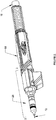
FIG. 2 is a perspective view of a power pin including the self-adjusting liner assembly and an associated welding torch body; -
FIG. 3 is a cross-sectional view of the power pin including the self-adjusting liner assembly and the welding torch body taken along the line 3-3 inFIG. 2 ; -
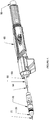
FIG. 4 is an exploded perspective view of a portion of the welding torch including the self-adjusting liner assembly; -
FIG. 5 is an exploded perspective view of the power pin and self-adjusting liner assembly; and -
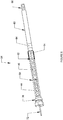
FIG. 6 is a perspective view of the self-adjusting liner assembly and an associated front load liner. - Referring now to the
FIG. 1 in detail,numeral 10 generally indicates a welding torch such as a gas metal arc welding (GMAW) torch, a metal inert gas (MIG) torch, or similar welding torch. Thewelding torch 10 broadly includes amain housing 12, agooseneck 14, and acontact tip assembly 16. Acable 18 is connected to a rearward end of themain housing 12 to supply gas, electrical current, and a consumable electrode (e.g., a metal welding wire) to thetorch 10. Thecable 18 may be connected via arear handle 68 to awire feeder 20 opposite themain housing 12. Thegooseneck 14 is operatively connected to a forward end of themain housing 12 and allows for the communication of the consumable electrode, the shielding gas, and the welding current to thecontact tip assembly 16 mounted on the gooseneck. Thewelding torch 10 also may be mounted to arobotic arm 22. - The
wire feeder 20 feeds the welding wire through thewelding torch 10, and ultimately through an orifice in thecontact tip assembly 16 at the forward end of the welding torch. The welding wire, when energized for welding, carries a high electrical potential. When the welding wire makes contact with target metal workpieces, an electrical circuit is completed and current flows through the welding wire, across the metal workpieces and to ground. The current causes the welding wire and the parent metal of the workpieces in contact with the welding wire to melt, thereby joining the workpieces as the melt solidifies. - With reference to
FIGS. 2 through 6 , thewelding torch 10 includes a self-adjustingliner assembly 24 in accordance with the invention. The self-adjustingliner assembly 24 includes an elongatedtubular body 26 which may be defined at least in part by a power pin or may be a tubular member that is separate from and connected to the power pin. In the embodiment shown in the drawings, the tubular body is entirely defined by the power pin. Thetubular body 26 has aforward end 28, arearward end 30, and a central bore or throughhole 32 extending from the forward end to the rearward end. Thebore 32 includes astop 34 in theforward end 28 for limiting the movement of a slide and aseat 36 in therearward end 30 for seating an inlet guide. - An
inlet guide 38 is disposed in therearward end 30 of thebody 26 and removably mounted therein thebore 32 adjacent theseat 36 such that the inlet guide engages the seat. Acap 39 may be attached to therearward end 30 of thebody 26 and may cover over theinlet guide 38. Theinlet guide 38 includes arecess 40 which is defined by an increased diameter portion of apassage 42 through the inlet guide. An elongated fixedtube 44 is received in therecess 40 of theinlet guide 38 and thereby mounted in thebore 32 of thebody 26 such that the fixed tube extends inwardly into the bore. - The
liner assembly 24 further includes an elongatedtubular slide 46 having aninner end 48, anouter end 50, ashoulder 52 proximate the outer end, and at least one longitudinally extendinggas passage 54 defined by one of a longitudinally extending recess disposed on the periphery of the shoulder and a longitudinally extending aperture through the shoulder. In a specific embodiment, theslide 46 includes a plurality ofgas passages 54. The gas passage(s) 54 allow for the passage of shielding gas through theslide 46. Theslide shoulder 52 is generally disposed toward theforward end 28 of thebody 26. Theslide 46 cooperates with the fixedtube 44 in a telescoping relationship in thebore 32 of thebody 26. In other words, anend 56 of the fixedtube 44 opposite theinlet guide 38 is received in theinner end 48 of theslide 46, and theslide 46 is slidable about the fixedtube 44, varying the distance between theshoulder 52 and theinlet guide 38. - A
resilient member 58 such as a spring, coil spring, or other resilient, compressible member is disposed in thebore 32 of thebody 26. Theresilient member 58 envelops a portion of the fixedtube 44 and theslide 46 between theslide shoulder 52 andinlet guide 38. One end of theresilient member 58 engages theslide shoulder 52 and an opposite end of the resilient member engages theinlet guide 38. Theresilient member 58 urges theslide 46 away from the fixedtube 44, causing the slide to be urged toward theforward end 28 of thebody 26. When theslide 46 is fully extended, it engages and is limited in motion by thestop 34. - The welding torch may also include a quick-load
front loading liner 60. Thefront loading liner 60 provides a channel for the welding wire from theliner assembly 24 through thegooseneck 14 into thecontact tip assembly 16. Theslide 46 may include aretainer 62 in theshoulder 52 generally adjacent theforward end 28 of thebody 26 at theouter end 50 of the slide. An end of thefront loading liner 60 may be inserted into thebore 32 of thebody 26 at the body forward end 28 and is receivable in theretainer 62. In a specific embodiment, thefront loading liner 60 may includeliner insert 64 defining the end of the liner and aflexible liner body 66 connected to or integral with the liner insert. Theliner body 66 may be a metal (e.g., aluminum) coil. In this embodiment, theliner insert 64 is inserted into theretainer 62 and releasably secured therein. - Referring now to
FIGS. 1 through 6 , the self-adjustingliner assembly 24 is positioned at the rearward end of thewelding torch 10. The forward end of the power pin including theliner assembly 24 is connected to therear handle 68, and therear handle 68 is operatively connected to thegooseneck 14 via thecable 18. Thus, therear handle 68 is intermediate thebody 26 of theliner assembly 24 and thegooseneck 14. Thecontact tip assembly 16 is connected to the forward end of thegooseneck 14 opposite theliner assembly 24 andrear handle 68. Thefront loading liner 60 is installed from the front of thewelding torch 10. To install theliner 60, the contact tip assembly 16 (which may include a retaining head and contact tip) may be removed from thewelding torch 10. Theliner 60 is then inserted from the front of thewelding torch 10 and fed into the welding torch. As theliner 60 is fed into the torch, the liner enters thebore 32 of thebody 26 from thegooseneck 14 andrear handle 68, and is received in thepiston recess 68, causing theliner 60 to become engaged with theretainer 62 in theslide 46. Theliner 60 is further urged into the torch to compress theresilient member 58 viaslide 46, and then the liner is cut approximately 5/8 of an inch from the forward end of thegooseneck 14. Thecontact tip assembly 16 may then be reinstalled on thewelding torch 10 at the forward end of thegooseneck 14. - At this time, the
slide 46 generally fully compresses theresilient member 58, and the counterforce of theresilient member 58 urges the slide forward. The force the resilient member exerts on the slide maintains engagement of the slide with theliner insert 64 of thefront loading liner 60 and engagement of theliner body 66 in thecontact tip assembly 16. - Welding
wire 72 is fed through the welding torch 10 (for example, by wire feeder 20) from the rear of the torch to the forward end of the torch. As it is fed, thewelding wire 72 passes through the guide cap 39 (if present) into the power pin, through thepassage 42 in theinlet guide 38 into the fixedtube 44, through the fixed tube into thetubular slide 46, through the tubular slide into thefront loading liner 60, and all the way through the front loading liner into thecontact tip assembly 16. As thewelding wire 72 passes through theliner assembly 24, the fixedtube 44 andtubular slide 46 support the welding wire and aid in preventing the wire from wandering or binding inside the liner assembly. - It is critical that the
liner 60 is seated properly directly behind the contact tip of thecontact tip assembly 16 at the front end of thetorch 10 to reduce wear of the contact tip and to maintain proper feeding of thewelding wire 72 into the contact tip. Advantageously, the self-adjustingliner assembly 24 constantly urges theliner 60 forward (via slide 46) into a mating seat in thecontact tip assembly 16, ensuring that liner is properly positioned in the contact tip and that thewelding wire 72 is properly fed into the contact tip. For example, as thewelding torch 10 is operated, it expands over time due to the thermal expansion of the materials of torch body caused by the heat of the welding process. Also, if theliner 60 is made of plastic, gas and heat may cause the liner, especially the front portion in thecontact tip assembly 16, to be consumed over time. Otherwise, if theliner 60 is made of metal or similar, the liner is not likely to be consumed. As thetorch 10 expands and/or theliner 60 is consumed, theslide 46 advances forward in thebore 32 of thebody 26, thereby continually urging theliner 60 forward such that the front end of theliner 60 is properly seated in thecontact tip assembly 16. In one embodiment, theslide 46 may be able to travel about one inch in thebore 32 before contacting thestop 34. When theslide shoulder 52 becomes engaged with thestop 34, theslide 46 is in its fully extended position (e.g., seeFIG. 3 ) and cannot move any farther forward. At this time, it may be necessary to replace thefront loading liner 60 and recompress theresilient member 58. - Although the invention has been described by reference to specific embodiments, it should be understood that numerous changes may be made within the scope of the inventive concepts described. Accordingly, it is intended that the invention not be limited to the described embodiments, but that it have the full scope defined by the language of the following claims.
Claims (11)
- A self-adjusting liner assembly (24) for a welding torch (10) comprising:an elongated tubular body (26) having a forward end (28), a rearward end (30), and a central bore (32) extending from said forward end (28) to said rearward end (30);an elongated fixed tube (44) mounted in said bore (32);an elongated tubular slide (46) having an inner end (48), an outer end (50), and a shoulder (52) proximate said outer end (50);said fixed tube (44) being received in said inner end of said slide (46), and said slide (46) cooperating with said fixed tube (44) in a telescoping relationship in said bore (32); anda resilient member (58) disposed in said bore (32) and enveloping a portion of said fixed tube (44) and said slide (46), said resilient member (58) engaging said shoulder (52) of said slide (46) and urging said slide (46) away from said fixed tube (44) and toward the forward end (28) of said body (26),said central bore (32) of the elongated tubular body (26) including a stop (34) in said forward end (28) for limiting the movement of the slide and a seat (36) in said rearward end (30),characterized in thatsaid self-adjusting liner assembly (24) further comprises an inlet guide (38) being removably disposed in said rearward end (30) of said elongated tubular body (26) engaging the seat (36) and including a recess (40), which is defined by an increased diameter portion of a passage (42) through the inlet guide, receiving the elongated fixed tube (44), and an opposite end of the resilient member (58) engaging the inlet guide (38).
- The self-adjusting liner assembly of claim 1, wherein said resilient member (58) is a spring.
- The self-adjusting liner assembly of claim 1, wherein said shoulder (52) of said slide (46) is urged toward said forward end (28) of said body (26).
- The self-adjusting liner assembly of claim 1, including a front loading liner (60) and wherein said slide (46) includes a retainer (62) at said outer end for receiving said front loading liner (60).
- The self-adjusting liner assembly of claim 4, wherein said front loading liner (60) includes a liner insert (64) and a liner body (66) connected to said liner insert (64), said liner insert (64) being receivable in said retainer(62) of said slide (46).
- The self-adjusting liner assembly of claim 1, wherein said slide (46) includes at least one longitudinally extending gas passage (54), said gas passage (54) being defined as one of a longitudinally extending recess disposed on the periphery of said shoulder (52) and a longitudinally extending aperture through said shoulder.
- A welding torch (10) comprising:a self-adjusting liner assembly (24) according to claim 1;a rear handle (68), said forward end of said power pin being removably mounted in said rear handle (68);a front handle;a gooseneck (14) having first and second ends, said first end being operatively connected to said front handle; anda contact tip assembly (16) mounted on said second end of said gooseneck (14).
- The welding torch of claim 7, including a front loading liner (60) that is inserted from said second end of said gooseneck (14) to said power pin mounted in said rear handle (68).
- The welding torch of claim 8, wherein said slide (46) includes a retainer (62) at said outer end for receiving said front loading liner (60).
- The welding torch of claim 9, wherein said front loading liner (60) includes a liner insert (64) and a liner body (66) connected to said liner insert (64), said liner insert (64) being receivable in said retainer (62) of said slide (46).
- The welding torch of claim 7, wherein said slide (46) includes at least one longitudinally extending gas (54) passage therethrough.
Applications Claiming Priority (2)
| Application Number | Priority Date | Filing Date | Title |
|---|---|---|---|
| US13/153,486 US8963046B2 (en) | 2007-03-08 | 2011-06-06 | Self-adjusting liner assembly for welding torch |
| PCT/US2012/040883 WO2012170403A1 (en) | 2011-06-06 | 2012-06-05 | Self-adjusting liner assembly for welding torch |
Publications (2)
| Publication Number | Publication Date |
|---|---|
| EP2718053A1 EP2718053A1 (en) | 2014-04-16 |
| EP2718053B1 true EP2718053B1 (en) | 2019-10-23 |
Family
ID=46298684
Family Applications (1)
| Application Number | Title | Priority Date | Filing Date |
|---|---|---|---|
| EP12727723.4A Active EP2718053B1 (en) | 2011-06-06 | 2012-06-05 | Self-adjusting liner assembly for welding torch |
Country Status (4)
| Country | Link |
|---|---|
| EP (1) | EP2718053B1 (en) |
| CA (1) | CA2834703C (en) |
| MX (1) | MX340282B (en) |
| WO (1) | WO2012170403A1 (en) |
Family Cites Families (3)
| Publication number | Priority date | Publication date | Assignee | Title |
|---|---|---|---|---|
| US7309844B2 (en) * | 2003-08-29 | 2007-12-18 | Tregaskiss Ltd. | Multi-piece front loading liner |
| US8373094B2 (en) * | 2007-03-08 | 2013-02-12 | Illinois Tool Works Inc. | Self-adjusting liner assembly for a consumable electrode arc-welding torch |
| US20100230395A1 (en) * | 2007-10-09 | 2010-09-16 | Matsushita Electric Industrial Co., Ltd. | Welding torch |
-
2012
- 2012-06-05 WO PCT/US2012/040883 patent/WO2012170403A1/en not_active Ceased
- 2012-06-05 EP EP12727723.4A patent/EP2718053B1/en active Active
- 2012-06-05 MX MX2013014426A patent/MX340282B/en active IP Right Grant
- 2012-06-05 CA CA2834703A patent/CA2834703C/en active Active
Non-Patent Citations (1)
| Title |
|---|
| None * |
Also Published As
| Publication number | Publication date |
|---|---|
| MX2013014426A (en) | 2014-01-20 |
| WO2012170403A1 (en) | 2012-12-13 |
| CA2834703A1 (en) | 2012-12-13 |
| EP2718053A1 (en) | 2014-04-16 |
| CA2834703C (en) | 2016-07-26 |
| MX340282B (en) | 2016-07-04 |
Similar Documents
| Publication | Publication Date | Title |
|---|---|---|
| EP2117759B1 (en) | Self-adjusting liner assembly for welding torch | |
| US8963046B2 (en) | Self-adjusting liner assembly for welding torch | |
| US8450646B2 (en) | Retaining head and contact tip for controlling wire contour and contacting point for GMAW torches | |
| JP5563571B2 (en) | Robotic GMAW torch with simple removable gooseneck locking mechanism, double alignment specific structure, and multiple electrical contacts | |
| EP1992206B1 (en) | Electrode for a contact start plasma arc torch and contact start plasma arc torch employing such electrodes | |
| EP3357625B1 (en) | Tip-retention device for use with a welding system | |
| EP3357626B1 (en) | Tip-retention device for use with a welding system | |
| US8304692B2 (en) | Forced pressure power supply torch | |
| CA2928856C (en) | Collar assembly for securing consumables of an arc welding apparatus | |
| US20140110386A1 (en) | Compressible end-fitting for welding gun liner | |
| US20130105453A1 (en) | Contact tip with contoured bore | |
| US10610948B2 (en) | Two-piece nozzle assembly for an arc welding apparatus | |
| EP2895291B1 (en) | Jump liner for push-pull mig torch with an elongated body made of flexible plastic material ; push-pull mig torch with such liner | |
| CN110740832B (en) | Welding system for cooling a welding contact tip | |
| CA2834703C (en) | Self-adjusting liner assembly for welding torch | |
| CA3066773C (en) | Contact tip, gas diffuser, and nozzle for welding torch | |
| JP2021176644A (en) | Electric power supply chip and welding torch | |
| US20200055137A1 (en) | Precision Wire Guide For A Welding Consumable | |
| KR20190109875A (en) | TIG welding torch with improved material supply structure |
Legal Events
| Date | Code | Title | Description |
|---|---|---|---|
| PUAI | Public reference made under article 153(3) epc to a published international application that has entered the european phase |
Free format text: ORIGINAL CODE: 0009012 |
|
| 17P | Request for examination filed |
Effective date: 20131030 |
|
| AK | Designated contracting states |
Kind code of ref document: A1 Designated state(s): AL AT BE BG CH CY CZ DE DK EE ES FI FR GB GR HR HU IE IS IT LI LT LU LV MC MK MT NL NO PL PT RO RS SE SI SK SM TR |
|
| DAX | Request for extension of the european patent (deleted) | ||
| 17Q | First examination report despatched |
Effective date: 20160909 |
|
| STAA | Information on the status of an ep patent application or granted ep patent |
Free format text: STATUS: EXAMINATION IS IN PROGRESS |
|
| GRAP | Despatch of communication of intention to grant a patent |
Free format text: ORIGINAL CODE: EPIDOSNIGR1 |
|
| STAA | Information on the status of an ep patent application or granted ep patent |
Free format text: STATUS: GRANT OF PATENT IS INTENDED |
|
| INTG | Intention to grant announced |
Effective date: 20190528 |
|
| GRAS | Grant fee paid |
Free format text: ORIGINAL CODE: EPIDOSNIGR3 |
|
| GRAA | (expected) grant |
Free format text: ORIGINAL CODE: 0009210 |
|
| STAA | Information on the status of an ep patent application or granted ep patent |
Free format text: STATUS: THE PATENT HAS BEEN GRANTED |
|
| AK | Designated contracting states |
Kind code of ref document: B1 Designated state(s): AL AT BE BG CH CY CZ DE DK EE ES FI FR GB GR HR HU IE IS IT LI LT LU LV MC MK MT NL NO PL PT RO RS SE SI SK SM TR |
|
| REG | Reference to a national code |
Ref country code: GB Ref legal event code: FG4D |
|
| RIN1 | Information on inventor provided before grant (corrected) |
Inventor name: PRATT, KENNETH K. Inventor name: WELLS, JEFFREY G. |
|
| REG | Reference to a national code |
Ref country code: CH Ref legal event code: EP |
|
| REG | Reference to a national code |
Ref country code: IE Ref legal event code: FG4D |
|
| REG | Reference to a national code |
Ref country code: DE Ref legal event code: R096 Ref document number: 602012065069 Country of ref document: DE |
|
| REG | Reference to a national code |
Ref country code: AT Ref legal event code: REF Ref document number: 1193132 Country of ref document: AT Kind code of ref document: T Effective date: 20191115 |
|
| REG | Reference to a national code |
Ref country code: NL Ref legal event code: MP Effective date: 20191023 |
|
| REG | Reference to a national code |
Ref country code: LT Ref legal event code: MG4D |
|
| PG25 | Lapsed in a contracting state [announced via postgrant information from national office to epo] |
Ref country code: SE Free format text: LAPSE BECAUSE OF FAILURE TO SUBMIT A TRANSLATION OF THE DESCRIPTION OR TO PAY THE FEE WITHIN THE PRESCRIBED TIME-LIMIT Effective date: 20191023 Ref country code: NL Free format text: LAPSE BECAUSE OF FAILURE TO SUBMIT A TRANSLATION OF THE DESCRIPTION OR TO PAY THE FEE WITHIN THE PRESCRIBED TIME-LIMIT Effective date: 20191023 Ref country code: LV Free format text: LAPSE BECAUSE OF FAILURE TO SUBMIT A TRANSLATION OF THE DESCRIPTION OR TO PAY THE FEE WITHIN THE PRESCRIBED TIME-LIMIT Effective date: 20191023 Ref country code: ES Free format text: LAPSE BECAUSE OF FAILURE TO SUBMIT A TRANSLATION OF THE DESCRIPTION OR TO PAY THE FEE WITHIN THE PRESCRIBED TIME-LIMIT Effective date: 20191023 Ref country code: LT Free format text: LAPSE BECAUSE OF FAILURE TO SUBMIT A TRANSLATION OF THE DESCRIPTION OR TO PAY THE FEE WITHIN THE PRESCRIBED TIME-LIMIT Effective date: 20191023 Ref country code: PT Free format text: LAPSE BECAUSE OF FAILURE TO SUBMIT A TRANSLATION OF THE DESCRIPTION OR TO PAY THE FEE WITHIN THE PRESCRIBED TIME-LIMIT Effective date: 20200224 Ref country code: FI Free format text: LAPSE BECAUSE OF FAILURE TO SUBMIT A TRANSLATION OF THE DESCRIPTION OR TO PAY THE FEE WITHIN THE PRESCRIBED TIME-LIMIT Effective date: 20191023 Ref country code: BG Free format text: LAPSE BECAUSE OF FAILURE TO SUBMIT A TRANSLATION OF THE DESCRIPTION OR TO PAY THE FEE WITHIN THE PRESCRIBED TIME-LIMIT Effective date: 20200123 Ref country code: GR Free format text: LAPSE BECAUSE OF FAILURE TO SUBMIT A TRANSLATION OF THE DESCRIPTION OR TO PAY THE FEE WITHIN THE PRESCRIBED TIME-LIMIT Effective date: 20200124 Ref country code: NO Free format text: LAPSE BECAUSE OF FAILURE TO SUBMIT A TRANSLATION OF THE DESCRIPTION OR TO PAY THE FEE WITHIN THE PRESCRIBED TIME-LIMIT Effective date: 20200123 Ref country code: PL Free format text: LAPSE BECAUSE OF FAILURE TO SUBMIT A TRANSLATION OF THE DESCRIPTION OR TO PAY THE FEE WITHIN THE PRESCRIBED TIME-LIMIT Effective date: 20191023 |
|
| PG25 | Lapsed in a contracting state [announced via postgrant information from national office to epo] |
Ref country code: IS Free format text: LAPSE BECAUSE OF FAILURE TO SUBMIT A TRANSLATION OF THE DESCRIPTION OR TO PAY THE FEE WITHIN THE PRESCRIBED TIME-LIMIT Effective date: 20200224 Ref country code: RS Free format text: LAPSE BECAUSE OF FAILURE TO SUBMIT A TRANSLATION OF THE DESCRIPTION OR TO PAY THE FEE WITHIN THE PRESCRIBED TIME-LIMIT Effective date: 20191023 Ref country code: HR Free format text: LAPSE BECAUSE OF FAILURE TO SUBMIT A TRANSLATION OF THE DESCRIPTION OR TO PAY THE FEE WITHIN THE PRESCRIBED TIME-LIMIT Effective date: 20191023 |
|
| PG25 | Lapsed in a contracting state [announced via postgrant information from national office to epo] |
Ref country code: AL Free format text: LAPSE BECAUSE OF FAILURE TO SUBMIT A TRANSLATION OF THE DESCRIPTION OR TO PAY THE FEE WITHIN THE PRESCRIBED TIME-LIMIT Effective date: 20191023 |
|
| REG | Reference to a national code |
Ref country code: DE Ref legal event code: R097 Ref document number: 602012065069 Country of ref document: DE |
|
| PG2D | Information on lapse in contracting state deleted |
Ref country code: IS |
|
| PG25 | Lapsed in a contracting state [announced via postgrant information from national office to epo] |
Ref country code: CZ Free format text: LAPSE BECAUSE OF FAILURE TO SUBMIT A TRANSLATION OF THE DESCRIPTION OR TO PAY THE FEE WITHIN THE PRESCRIBED TIME-LIMIT Effective date: 20191023 Ref country code: RO Free format text: LAPSE BECAUSE OF FAILURE TO SUBMIT A TRANSLATION OF THE DESCRIPTION OR TO PAY THE FEE WITHIN THE PRESCRIBED TIME-LIMIT Effective date: 20191023 Ref country code: DK Free format text: LAPSE BECAUSE OF FAILURE TO SUBMIT A TRANSLATION OF THE DESCRIPTION OR TO PAY THE FEE WITHIN THE PRESCRIBED TIME-LIMIT Effective date: 20191023 Ref country code: EE Free format text: LAPSE BECAUSE OF FAILURE TO SUBMIT A TRANSLATION OF THE DESCRIPTION OR TO PAY THE FEE WITHIN THE PRESCRIBED TIME-LIMIT Effective date: 20191023 Ref country code: IS Free format text: LAPSE BECAUSE OF FAILURE TO SUBMIT A TRANSLATION OF THE DESCRIPTION OR TO PAY THE FEE WITHIN THE PRESCRIBED TIME-LIMIT Effective date: 20200223 |
|
| PGFP | Annual fee paid to national office [announced via postgrant information from national office to epo] |
Ref country code: FR Payment date: 20200625 Year of fee payment: 9 |
|
| REG | Reference to a national code |
Ref country code: AT Ref legal event code: MK05 Ref document number: 1193132 Country of ref document: AT Kind code of ref document: T Effective date: 20191023 |
|
| PLBE | No opposition filed within time limit |
Free format text: ORIGINAL CODE: 0009261 |
|
| STAA | Information on the status of an ep patent application or granted ep patent |
Free format text: STATUS: NO OPPOSITION FILED WITHIN TIME LIMIT |
|
| PG25 | Lapsed in a contracting state [announced via postgrant information from national office to epo] |
Ref country code: SK Free format text: LAPSE BECAUSE OF FAILURE TO SUBMIT A TRANSLATION OF THE DESCRIPTION OR TO PAY THE FEE WITHIN THE PRESCRIBED TIME-LIMIT Effective date: 20191023 Ref country code: SM Free format text: LAPSE BECAUSE OF FAILURE TO SUBMIT A TRANSLATION OF THE DESCRIPTION OR TO PAY THE FEE WITHIN THE PRESCRIBED TIME-LIMIT Effective date: 20191023 |
|
| PGFP | Annual fee paid to national office [announced via postgrant information from national office to epo] |
Ref country code: GB Payment date: 20200629 Year of fee payment: 9 |
|
| 26N | No opposition filed |
Effective date: 20200724 |
|
| PG25 | Lapsed in a contracting state [announced via postgrant information from national office to epo] |
Ref country code: AT Free format text: LAPSE BECAUSE OF FAILURE TO SUBMIT A TRANSLATION OF THE DESCRIPTION OR TO PAY THE FEE WITHIN THE PRESCRIBED TIME-LIMIT Effective date: 20191023 Ref country code: SI Free format text: LAPSE BECAUSE OF FAILURE TO SUBMIT A TRANSLATION OF THE DESCRIPTION OR TO PAY THE FEE WITHIN THE PRESCRIBED TIME-LIMIT Effective date: 20191023 |
|
| PG25 | Lapsed in a contracting state [announced via postgrant information from national office to epo] |
Ref country code: MC Free format text: LAPSE BECAUSE OF FAILURE TO SUBMIT A TRANSLATION OF THE DESCRIPTION OR TO PAY THE FEE WITHIN THE PRESCRIBED TIME-LIMIT Effective date: 20191023 |
|
| REG | Reference to a national code |
Ref country code: CH Ref legal event code: PL |
|
| PG25 | Lapsed in a contracting state [announced via postgrant information from national office to epo] |
Ref country code: LU Free format text: LAPSE BECAUSE OF NON-PAYMENT OF DUE FEES Effective date: 20200605 |
|
| REG | Reference to a national code |
Ref country code: BE Ref legal event code: MM Effective date: 20200630 |
|
| PG25 | Lapsed in a contracting state [announced via postgrant information from national office to epo] |
Ref country code: LI Free format text: LAPSE BECAUSE OF NON-PAYMENT OF DUE FEES Effective date: 20200630 Ref country code: IE Free format text: LAPSE BECAUSE OF NON-PAYMENT OF DUE FEES Effective date: 20200605 Ref country code: CH Free format text: LAPSE BECAUSE OF NON-PAYMENT OF DUE FEES Effective date: 20200630 |
|
| PG25 | Lapsed in a contracting state [announced via postgrant information from national office to epo] |
Ref country code: BE Free format text: LAPSE BECAUSE OF NON-PAYMENT OF DUE FEES Effective date: 20200630 |
|
| GBPC | Gb: european patent ceased through non-payment of renewal fee |
Effective date: 20210605 |
|
| PG25 | Lapsed in a contracting state [announced via postgrant information from national office to epo] |
Ref country code: GB Free format text: LAPSE BECAUSE OF NON-PAYMENT OF DUE FEES Effective date: 20210605 |
|
| PG25 | Lapsed in a contracting state [announced via postgrant information from national office to epo] |
Ref country code: TR Free format text: LAPSE BECAUSE OF FAILURE TO SUBMIT A TRANSLATION OF THE DESCRIPTION OR TO PAY THE FEE WITHIN THE PRESCRIBED TIME-LIMIT Effective date: 20191023 Ref country code: MT Free format text: LAPSE BECAUSE OF FAILURE TO SUBMIT A TRANSLATION OF THE DESCRIPTION OR TO PAY THE FEE WITHIN THE PRESCRIBED TIME-LIMIT Effective date: 20191023 Ref country code: FR Free format text: LAPSE BECAUSE OF NON-PAYMENT OF DUE FEES Effective date: 20210630 Ref country code: CY Free format text: LAPSE BECAUSE OF FAILURE TO SUBMIT A TRANSLATION OF THE DESCRIPTION OR TO PAY THE FEE WITHIN THE PRESCRIBED TIME-LIMIT Effective date: 20191023 |
|
| PG25 | Lapsed in a contracting state [announced via postgrant information from national office to epo] |
Ref country code: MK Free format text: LAPSE BECAUSE OF FAILURE TO SUBMIT A TRANSLATION OF THE DESCRIPTION OR TO PAY THE FEE WITHIN THE PRESCRIBED TIME-LIMIT Effective date: 20191023 |
|
| P01 | Opt-out of the competence of the unified patent court (upc) registered |
Effective date: 20230606 |
|
| PGFP | Annual fee paid to national office [announced via postgrant information from national office to epo] |
Ref country code: DE Payment date: 20250627 Year of fee payment: 14 |
|
| PGFP | Annual fee paid to national office [announced via postgrant information from national office to epo] |
Ref country code: IT Payment date: 20250619 Year of fee payment: 14 |