EP2717992B1 - Porous adsorbent structure for adsorption of co2 from a gas mixture - Google Patents
Porous adsorbent structure for adsorption of co2 from a gas mixture Download PDFInfo
- Publication number
- EP2717992B1 EP2717992B1 EP12725832.5A EP12725832A EP2717992B1 EP 2717992 B1 EP2717992 B1 EP 2717992B1 EP 12725832 A EP12725832 A EP 12725832A EP 2717992 B1 EP2717992 B1 EP 2717992B1
- Authority
- EP
- European Patent Office
- Prior art keywords
- solvent
- cellulose nanofibers
- coupling agent
- suspension
- cellulose
- Prior art date
- Legal status (The legal status is an assumption and is not a legal conclusion. Google has not performed a legal analysis and makes no representation as to the accuracy of the status listed.)
- Active
Links
Images

Classifications
-
- B—PERFORMING OPERATIONS; TRANSPORTING
- B01—PHYSICAL OR CHEMICAL PROCESSES OR APPARATUS IN GENERAL
- B01D—SEPARATION
- B01D53/00—Separation of gases or vapours; Recovering vapours of volatile solvents from gases; Chemical or biological purification of waste gases, e.g. engine exhaust gases, smoke, fumes, flue gases, aerosols
- B01D53/34—Chemical or biological purification of waste gases
- B01D53/46—Removing components of defined structure
- B01D53/62—Carbon oxides
-
- B—PERFORMING OPERATIONS; TRANSPORTING
- B01—PHYSICAL OR CHEMICAL PROCESSES OR APPARATUS IN GENERAL
- B01D—SEPARATION
- B01D53/00—Separation of gases or vapours; Recovering vapours of volatile solvents from gases; Chemical or biological purification of waste gases, e.g. engine exhaust gases, smoke, fumes, flue gases, aerosols
- B01D53/02—Separation of gases or vapours; Recovering vapours of volatile solvents from gases; Chemical or biological purification of waste gases, e.g. engine exhaust gases, smoke, fumes, flue gases, aerosols by adsorption, e.g. preparative gas chromatography
-
- B—PERFORMING OPERATIONS; TRANSPORTING
- B01—PHYSICAL OR CHEMICAL PROCESSES OR APPARATUS IN GENERAL
- B01J—CHEMICAL OR PHYSICAL PROCESSES, e.g. CATALYSIS OR COLLOID CHEMISTRY; THEIR RELEVANT APPARATUS
- B01J20/00—Solid sorbent compositions or filter aid compositions; Sorbents for chromatography; Processes for preparing, regenerating or reactivating thereof
- B01J20/28—Solid sorbent compositions or filter aid compositions; Sorbents for chromatography; Processes for preparing, regenerating or reactivating thereof characterised by their form or physical properties
-
- B—PERFORMING OPERATIONS; TRANSPORTING
- B01—PHYSICAL OR CHEMICAL PROCESSES OR APPARATUS IN GENERAL
- B01J—CHEMICAL OR PHYSICAL PROCESSES, e.g. CATALYSIS OR COLLOID CHEMISTRY; THEIR RELEVANT APPARATUS
- B01J20/00—Solid sorbent compositions or filter aid compositions; Sorbents for chromatography; Processes for preparing, regenerating or reactivating thereof
- B01J20/28—Solid sorbent compositions or filter aid compositions; Sorbents for chromatography; Processes for preparing, regenerating or reactivating thereof characterised by their form or physical properties
- B01J20/28002—Solid sorbent compositions or filter aid compositions; Sorbents for chromatography; Processes for preparing, regenerating or reactivating thereof characterised by their form or physical properties characterised by their physical properties
- B01J20/28004—Sorbent size or size distribution, e.g. particle size
- B01J20/28007—Sorbent size or size distribution, e.g. particle size with size in the range 1-100 nanometers, e.g. nanosized particles, nanofibers, nanotubes, nanowires or the like
-
- B—PERFORMING OPERATIONS; TRANSPORTING
- B01—PHYSICAL OR CHEMICAL PROCESSES OR APPARATUS IN GENERAL
- B01J—CHEMICAL OR PHYSICAL PROCESSES, e.g. CATALYSIS OR COLLOID CHEMISTRY; THEIR RELEVANT APPARATUS
- B01J20/00—Solid sorbent compositions or filter aid compositions; Sorbents for chromatography; Processes for preparing, regenerating or reactivating thereof
- B01J20/28—Solid sorbent compositions or filter aid compositions; Sorbents for chromatography; Processes for preparing, regenerating or reactivating thereof characterised by their form or physical properties
- B01J20/28014—Solid sorbent compositions or filter aid compositions; Sorbents for chromatography; Processes for preparing, regenerating or reactivating thereof characterised by their form or physical properties characterised by their form
- B01J20/28023—Fibres or filaments
-
- B—PERFORMING OPERATIONS; TRANSPORTING
- B01—PHYSICAL OR CHEMICAL PROCESSES OR APPARATUS IN GENERAL
- B01J—CHEMICAL OR PHYSICAL PROCESSES, e.g. CATALYSIS OR COLLOID CHEMISTRY; THEIR RELEVANT APPARATUS
- B01J20/00—Solid sorbent compositions or filter aid compositions; Sorbents for chromatography; Processes for preparing, regenerating or reactivating thereof
- B01J20/30—Processes for preparing, regenerating, or reactivating
- B01J20/32—Impregnating or coating ; Solid sorbent compositions obtained from processes involving impregnating or coating
-
- B—PERFORMING OPERATIONS; TRANSPORTING
- B01—PHYSICAL OR CHEMICAL PROCESSES OR APPARATUS IN GENERAL
- B01J—CHEMICAL OR PHYSICAL PROCESSES, e.g. CATALYSIS OR COLLOID CHEMISTRY; THEIR RELEVANT APPARATUS
- B01J20/00—Solid sorbent compositions or filter aid compositions; Sorbents for chromatography; Processes for preparing, regenerating or reactivating thereof
- B01J20/30—Processes for preparing, regenerating, or reactivating
- B01J20/32—Impregnating or coating ; Solid sorbent compositions obtained from processes involving impregnating or coating
- B01J20/3202—Impregnating or coating ; Solid sorbent compositions obtained from processes involving impregnating or coating characterised by the carrier, support or substrate used for impregnation or coating
- B01J20/3206—Organic carriers, supports or substrates
- B01J20/3208—Polymeric carriers, supports or substrates
- B01J20/3212—Polymeric carriers, supports or substrates consisting of a polymer obtained by reactions otherwise than involving only carbon to carbon unsaturated bonds
-
- B—PERFORMING OPERATIONS; TRANSPORTING
- B01—PHYSICAL OR CHEMICAL PROCESSES OR APPARATUS IN GENERAL
- B01J—CHEMICAL OR PHYSICAL PROCESSES, e.g. CATALYSIS OR COLLOID CHEMISTRY; THEIR RELEVANT APPARATUS
- B01J20/00—Solid sorbent compositions or filter aid compositions; Sorbents for chromatography; Processes for preparing, regenerating or reactivating thereof
- B01J20/30—Processes for preparing, regenerating, or reactivating
- B01J20/32—Impregnating or coating ; Solid sorbent compositions obtained from processes involving impregnating or coating
- B01J20/3214—Impregnating or coating ; Solid sorbent compositions obtained from processes involving impregnating or coating characterised by the method for obtaining this coating or impregnating
- B01J20/3217—Resulting in a chemical bond between the coating or impregnating layer and the carrier, support or substrate, e.g. a covalent bond
- B01J20/3219—Resulting in a chemical bond between the coating or impregnating layer and the carrier, support or substrate, e.g. a covalent bond involving a particular spacer or linking group, e.g. for attaching an active group
-
- B—PERFORMING OPERATIONS; TRANSPORTING
- B01—PHYSICAL OR CHEMICAL PROCESSES OR APPARATUS IN GENERAL
- B01J—CHEMICAL OR PHYSICAL PROCESSES, e.g. CATALYSIS OR COLLOID CHEMISTRY; THEIR RELEVANT APPARATUS
- B01J20/00—Solid sorbent compositions or filter aid compositions; Sorbents for chromatography; Processes for preparing, regenerating or reactivating thereof
- B01J20/30—Processes for preparing, regenerating, or reactivating
- B01J20/32—Impregnating or coating ; Solid sorbent compositions obtained from processes involving impregnating or coating
- B01J20/3231—Impregnating or coating ; Solid sorbent compositions obtained from processes involving impregnating or coating characterised by the coating or impregnating layer
- B01J20/3242—Layers with a functional group, e.g. an affinity material, a ligand, a reactant or a complexing group
- B01J20/3244—Non-macromolecular compounds
- B01J20/3246—Non-macromolecular compounds having a well defined chemical structure
- B01J20/3257—Non-macromolecular compounds having a well defined chemical structure the functional group or the linking, spacer or anchoring group as a whole comprising at least one of the heteroatoms nitrogen, oxygen or sulfur together with at least one silicon atom, these atoms not being part of the carrier as such
- B01J20/3259—Non-macromolecular compounds having a well defined chemical structure the functional group or the linking, spacer or anchoring group as a whole comprising at least one of the heteroatoms nitrogen, oxygen or sulfur together with at least one silicon atom, these atoms not being part of the carrier as such comprising at least two different types of heteroatoms selected from nitrogen, oxygen or sulfur with at least one silicon atom
-
- B—PERFORMING OPERATIONS; TRANSPORTING
- B01—PHYSICAL OR CHEMICAL PROCESSES OR APPARATUS IN GENERAL
- B01J—CHEMICAL OR PHYSICAL PROCESSES, e.g. CATALYSIS OR COLLOID CHEMISTRY; THEIR RELEVANT APPARATUS
- B01J20/00—Solid sorbent compositions or filter aid compositions; Sorbents for chromatography; Processes for preparing, regenerating or reactivating thereof
- B01J20/30—Processes for preparing, regenerating, or reactivating
- B01J20/32—Impregnating or coating ; Solid sorbent compositions obtained from processes involving impregnating or coating
- B01J20/3291—Characterised by the shape of the carrier, the coating or the obtained coated product
- B01J20/3293—Coatings on a core, the core being particle or fiber shaped, e.g. encapsulated particles, coated fibers
-
- B—PERFORMING OPERATIONS; TRANSPORTING
- B82—NANOTECHNOLOGY
- B82Y—SPECIFIC USES OR APPLICATIONS OF NANOSTRUCTURES; MEASUREMENT OR ANALYSIS OF NANOSTRUCTURES; MANUFACTURE OR TREATMENT OF NANOSTRUCTURES
- B82Y30/00—Nanotechnology for materials or surface science, e.g. nanocomposites
-
- B—PERFORMING OPERATIONS; TRANSPORTING
- B01—PHYSICAL OR CHEMICAL PROCESSES OR APPARATUS IN GENERAL
- B01D—SEPARATION
- B01D2253/00—Adsorbents used in seperation treatment of gases and vapours
- B01D2253/20—Organic adsorbents
- B01D2253/202—Polymeric adsorbents
-
- B—PERFORMING OPERATIONS; TRANSPORTING
- B01—PHYSICAL OR CHEMICAL PROCESSES OR APPARATUS IN GENERAL
- B01D—SEPARATION
- B01D2253/00—Adsorbents used in seperation treatment of gases and vapours
- B01D2253/25—Coated, impregnated or composite adsorbents
-
- B—PERFORMING OPERATIONS; TRANSPORTING
- B01—PHYSICAL OR CHEMICAL PROCESSES OR APPARATUS IN GENERAL
- B01D—SEPARATION
- B01D2253/00—Adsorbents used in seperation treatment of gases and vapours
- B01D2253/30—Physical properties of adsorbents
- B01D2253/302—Dimensions
- B01D2253/304—Linear dimensions, e.g. particle shape, diameter
-
- B—PERFORMING OPERATIONS; TRANSPORTING
- B01—PHYSICAL OR CHEMICAL PROCESSES OR APPARATUS IN GENERAL
- B01D—SEPARATION
- B01D2253/00—Adsorbents used in seperation treatment of gases and vapours
- B01D2253/30—Physical properties of adsorbents
- B01D2253/302—Dimensions
- B01D2253/311—Porosity, e.g. pore volume
-
- B—PERFORMING OPERATIONS; TRANSPORTING
- B01—PHYSICAL OR CHEMICAL PROCESSES OR APPARATUS IN GENERAL
- B01D—SEPARATION
- B01D2257/00—Components to be removed
- B01D2257/50—Carbon oxides
- B01D2257/504—Carbon dioxide
-
- B—PERFORMING OPERATIONS; TRANSPORTING
- B01—PHYSICAL OR CHEMICAL PROCESSES OR APPARATUS IN GENERAL
- B01D—SEPARATION
- B01D2258/00—Sources of waste gases
- B01D2258/06—Polluted air
-
- B—PERFORMING OPERATIONS; TRANSPORTING
- B01—PHYSICAL OR CHEMICAL PROCESSES OR APPARATUS IN GENERAL
- B01J—CHEMICAL OR PHYSICAL PROCESSES, e.g. CATALYSIS OR COLLOID CHEMISTRY; THEIR RELEVANT APPARATUS
- B01J2220/00—Aspects relating to sorbent materials
- B01J2220/40—Aspects relating to the composition of sorbent or filter aid materials
- B01J2220/48—Sorbents characterised by the starting material used for their preparation
- B01J2220/4812—Sorbents characterised by the starting material used for their preparation the starting material being of organic character
- B01J2220/4825—Polysaccharides or cellulose materials, e.g. starch, chitin, sawdust, wood, straw, cotton
-
- Y—GENERAL TAGGING OF NEW TECHNOLOGICAL DEVELOPMENTS; GENERAL TAGGING OF CROSS-SECTIONAL TECHNOLOGIES SPANNING OVER SEVERAL SECTIONS OF THE IPC; TECHNICAL SUBJECTS COVERED BY FORMER USPC CROSS-REFERENCE ART COLLECTIONS [XRACs] AND DIGESTS
- Y02—TECHNOLOGIES OR APPLICATIONS FOR MITIGATION OR ADAPTATION AGAINST CLIMATE CHANGE
- Y02A—TECHNOLOGIES FOR ADAPTATION TO CLIMATE CHANGE
- Y02A50/00—TECHNOLOGIES FOR ADAPTATION TO CLIMATE CHANGE in human health protection, e.g. against extreme weather
- Y02A50/20—Air quality improvement or preservation, e.g. vehicle emission control or emission reduction by using catalytic converters
-
- Y—GENERAL TAGGING OF NEW TECHNOLOGICAL DEVELOPMENTS; GENERAL TAGGING OF CROSS-SECTIONAL TECHNOLOGIES SPANNING OVER SEVERAL SECTIONS OF THE IPC; TECHNICAL SUBJECTS COVERED BY FORMER USPC CROSS-REFERENCE ART COLLECTIONS [XRACs] AND DIGESTS
- Y02—TECHNOLOGIES OR APPLICATIONS FOR MITIGATION OR ADAPTATION AGAINST CLIMATE CHANGE
- Y02C—CAPTURE, STORAGE, SEQUESTRATION OR DISPOSAL OF GREENHOUSE GASES [GHG]
- Y02C20/00—Capture or disposal of greenhouse gases
- Y02C20/40—Capture or disposal of greenhouse gases of CO2
-
- Y—GENERAL TAGGING OF NEW TECHNOLOGICAL DEVELOPMENTS; GENERAL TAGGING OF CROSS-SECTIONAL TECHNOLOGIES SPANNING OVER SEVERAL SECTIONS OF THE IPC; TECHNICAL SUBJECTS COVERED BY FORMER USPC CROSS-REFERENCE ART COLLECTIONS [XRACs] AND DIGESTS
- Y10—TECHNICAL SUBJECTS COVERED BY FORMER USPC
- Y10T—TECHNICAL SUBJECTS COVERED BY FORMER US CLASSIFICATION
- Y10T442/00—Fabric [woven, knitted, or nonwoven textile or cloth, etc.]
- Y10T442/60—Nonwoven fabric [i.e., nonwoven strand or fiber material]
- Y10T442/603—Including strand or fiber material precoated with other than free metal or alloy
Definitions
- the present invention generally relates to porous adsorbent structures for adsorption of CO 2 from a gas mixture, to methods for producing such structures and to uses thereof.
- Amine modified solid sorbents are known to be suitable for CO 2 capture from gas streams like flue gases or air (see e.g. WO 2010/091831 and references cited therein).
- Generally amine modified solid sorbents describe a class of materials where amines are immobilized on a porous solid substrate, either through physisorption or covalent bonding.
- several different solid supports and amines have been investigated for CO 2 capture.
- Cellulose is obtained from plants in the form of fibers having a diameter of about 30 to 100 ⁇ m and a length of several millimeters. These cellulose fibers are composed of cellulose microfibrils with a diameter of 2 to 10 nm and a length of several tens of microns formed during biosynthesis in higher plants.
- the disintegration of cellulose fibers to microfibrils aggregates is well known and was first described in US 4483743 .
- cellulose fibrils were produced that had a diameter of 4 nm to 1 ⁇ m and a length of 100 nm to 1 mm, which will be referred to as cellulose nanofibers hereinbelow.
- NFC nanofibrillated cellulose
- MFC microfibrillated cellulose
- amine modified cellulose nanofibers have been used for composite structures ( WO 2010/066905 ) and as antimicrobial tissues.
- the state of the art preparation method for amine modified cellulose nanofibers is to immerse the aminosilane and cellulose nanofibers in an aqueous or alcoholic solution, stir the resulting mixture and filter the wet slurry. The wet slurry is then either oven or air dried. Thereby, non-porous, densely packed amine modified cellulose nanofiber films are created. These films are not appropriate for CO 2 capture as the reactive amine sites are not accessible for the CO 2 molecules.
- the porous adsorbent structures comprise a support matrix of surface modified cellulose nanofibers, which surface modified cellulose nanofibers consist of cellulose nanofibers having a diameter of about 4 nm to about 1000 nm covered with a coupling agent being covalently bound to the surface thereof.
- the support matrix is a web of nanofibers with a porosity of at least 20%, preferably above 50%, even more preferably above 60%, where porosity is defined as the volume of the void over the total volume, and the coupling agent comprises at least one monoalkyldialkoxyaminosilane.
- the porous web of cellulose nanofibers can have the properties of an aerogel.
- cellulose nanofiber is defined as a cellulose fiber-like nanostructure with a diameter varying from about 4 to about 1000 nm, which includes, in particular but not exclusively, cellulose nanofibrils having a length of about 1 ⁇ m or more and cellulose nanowhiskers having a length of about 100 to 500 nm and a diameter below 10 nm.
- aerogels are solid materials with high porosity and surface area, low density and other interesting mechanical and non-mechanical properties. Aerogels made from cellulose have been known for some time, and prepared from NFC suspensions, from bacterial cellulose, from cellulose nanoparticles ( WO 2011/030170 ), from cellulose nanowhiskers and through dissolving cellulose. In analogy with the definitions used in WO 2011/ 030170 the term "aerogel” shall be understood here as an open porous structure with a porosity of at least 20%.
- the support matrices used in the present invention can be prepared with varying degrees of porosity above 20%, preferably above 50%, and even more preferably above 60%. They will generally have a BET (Brunauer-Emmett-Teller) surface area exceeding 2 m 2 /g, preferably more than 5 m 2 /g, and even more preferably more than 6 m 2 /g.
- BET Brunauer-Emmett-Teller
- the cellulose nanofiber material used to prepare the nanofiber webs according to the present invention will often contain a certain amount of long fibers and/or larger diameter fibers, henceforth briefly called “large cellulose fibers”.
- "large cellulose fibers” are defined as having a diameter in the range of more than 1 ⁇ m up to the diameter of the pristine plant fiber, i.e. 30 ⁇ m to 100 ⁇ m, and/or having a length exceeding 1 mm.
- a key requirement of the invention is the presence of a sufficiently large proportion of small cellulose nanofibers having a diameter not exceeding 1000 nm.
- the average diameter of the cellulose nanofibers shall be small enough so that suspending 2% w/w of the cellulose nanofiber material in water will form a hydrogel having a viscosity of at least 2000 mPa*s at a shear rate of 0.1 Hz.
- the coupling agent shall comprise at least one monoalkyldialkoxyaminosilane.
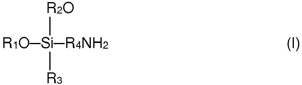
- This term shall be understood here to designate an aminofunctional silane compound with the general formula (I) wherein R 1 , R 2 and R 3 are independently selected C1-C5 alkyl groups.
- R 1 , R 2 and R 3 are selected from methyl and ethyl, and preferably R 1 and R 2 are identical.
- the group R 4 is a linear or branched C3-C12 alkyl moiety wherein one or more of the CH 2 groups is optionally replaced by a NH group. In general the presence of such NH groups provides additional amine functionality to the silane agent.
- Such compounds are generally known and can partly be purchased from various suppliers. Preferred selections of these silane compounds are discussed further below.
- adsorbent structure with highly advantageous properties.
- Such adsorbent structure is capable of a reversible adsorption and desorption cycle for capturing CO 2 from a gas mixture.
- monoalkyldialkoxyaminosilanes give substantially better results than the trialkoxyaminosilanes used in the prior art.
- a key feature of the present invention is the presence of monoalkyldialkoxyaminosilane.
- patent documents JP 2008 2666630 A and EP 2196478 both disclose some type of structure containing cellulose nanofibers partially covered by a monoalkyldialkoxyaminosilane, they do not refer to the task of CO 2 adsorption and the related key feature of using a monoalkyldialkoxysilane. They do not disclose any specific method steps aimed at producing a highly porous structure as in the present invention. Rather than that, they generally seek to provide materials with improved mechanical properties.
- the adsorbent structures produced according to the present invention have good recyclability, i.e. they can be subjected to a large number of CO 2 adsorption/desorption cycles without any substantial loss of performance. Moreover, they operate in a dry state, i.e. unlike some previously disclosed adsorbent structures they do not require wetting with a liquid able to react with CO 2 .
- the adsorbent structures are used for removing CO 2 from ambient air. It is contemplated that the adsorbent structures may also be used for other reactive species such as SO 2 .
- said regenerating step d) may be carried out "offline", i.e. by removing said adsorbent structure and taking the same to a suitable regeneration device. To this end it may be useful to utilize a plurality of adsorbent structures so as to avoid extended process interruption time.
- a method for producing a porous adsorbent structure as defined above which method comprises the steps of:
- the above defined method starts with a homogenized suspension of cellulose nanofibers, which may be obtained by various known means, to which is added the selected coupling agent.
- the choice of solvent will depend on various factors, including the selected coupling agent, the hydrolysis of the selected coupling agent, the drying method, environmental considerations and economics.
- an aqueous medium particularly deionized water.
- the aqueous medium is acidified, preferably with acetic acid or CO 2 .
- the aqueous medium is acidified with CO 2 .
- the removal of the solvent is carried out by a method that does not cause a collapse of the porous structure. Accordingly, the solvent is removed by freeze drying, atmospheric freeze drying, air drying, vacuum drying, heating or a combination thereof, preferably freeze drying.
- a method for producing a porous adsorbent structure as defined above said support matrix further comprising an admixture of large cellulose fibers, said large cellulose fibers having a diameter of more than 1 ⁇ m and/or a length exceeding 1 mm, the method comprising the steps of:
- the choice of solvent will depend on various factors, including the selected coupling agent, the hydrolysis of the selected coupling agent, the drying method, environmental considerations and economics. In many applications of this further method it will be preferable to use ethanol.
- the optional washing step d) and e), respectively, in the above defined methods allows recuperation of not adsorbed coupling agent and thus contributes to an economically and ecologically improved process.
- the coupling agent comprises just one monoalkyldialkoxyaminosilane.
- the invention is not limited to such cases, and it may actually be advantageous if the coupling agent comprises at least one further monoalkyldialkoxyaminosilane.
- the compound class of monoalkyldialkoxyaminosilanes as defined above comprises a large number of compounds. It is generally understood that the two alkoxy groups R 1 O and R 2 O,which preferably are identical, e.g. two methoxy or two ethoxy groups, provide the functionality for covalent coupling to the cellulose nanofiber structure. This bonding takes place by hydrolysis of the alkoxy-group(s), followed by the condensation of the generated silanol groups with the hydroxyl-groups on the surface of the nanofibers. In contrast, the alkyl group R 3 will generally act as an inert moiety in the present application context. The amine group, on the other hand, plays an important role for the capture of CO 2 molecules.
- a coupling agent predominantly comprising one or more monoalkyldialkoxyaminosilanes leads to surprisingly good results in terms of overall performance of the adsorbent structure. Without being bound by theory, it appears that these advantageous effects are related to the fact that monoalkyldialkoxyaminosilanes on the one hand do not form any 3-dimensional polysiloxanes but on the other hand are capable of forming the required porous adsorbent structure by forming linear structures.
- each one of the monoalkyldialkoxyaminosilane is selected from the group consisting of:
- the first compound 3-aminopropylmethyldiethoxysilane (CAS 3179-76-8), is a monoamine functional silane with the reactive amine group located at the distal end of the propyl substituent.
- the second compound N-(2-Aminoethyl)-3-aminopropyl-methyldimethoxysilane (CAS 3069-29-2), is a diamine functional silane wherein one of the hydrogens of the reactive amine group of the above mentioned first compound is replaced by an aminoethyl group.
- the third compound N-(3-Methyldimethoxysilylpropyl)diethylenetriamine, is a triamine functional silane wherein one of the hydrogens of the reactive amine group of the above mentioned second compound is replaced by an aminoethyl group.
- the first two compounds can be purchased whereas the third compound can be synthesized by known methods.
- the coupling agent further comprises a trialkoxyaminosilane in an amount of up to 60% by weight with respect to the total coupling agent weight.
- the term "trialkoxyaminosilane” shall be understood here to designate an aminofunctional silane compound with the general formula (II) wherein R 5 , R 6 and R 7 are independently selected C1-C5 alkyl groups. Preferably, R 5 , R 6 and R 7 are selected from methyl and ethyl, and preferably they are identical.
- the group R 8 is a linear or branched C3-C12 alkyl moiety wherein one or more of the CH 2 groups is optionally replaced by an NH group.
- the coupling agent further comprises a trialkoxyaminosilane in an amount of up to 25% by weight with respect to the total coupling agent weight.
- the trialkoxyaminosilane(s) is/are selected from the group consisting of:
- the adsorbent structure may further comprise a reinforcing structure.
- Such reinforcing structures may have a variety of configurations depending on the application. For example, they may be formed by an admixture of long reinforcing fibers or by a honeycomb structure.
- a reinforcing fiber mat is used to form CO 2 adsorber panels of approximately A4-size (i.e. approximately 21 x 30 cm) or 15 x 15 cm, but of course any other sizes are possible.
- freeze drying methods comprising vacuum freeze drying and atmospheric freeze drying readily work with any cellulose nanofiber material as defined further above, this is not always the case for non-freeze drying methods such as air drying.
- air drying was found to produce comparatively low porosity structures when using high-quality cellulose nanofiber material having only small amounts of large cellulose fibers. Therefore, an economically and ecologically advantageous embodiment of the invention relies on using lower quality cellulose nanofiber material having an appreciable admixture of large cellulose fibers and applying a non-freeze drying method.
- FIG. 1 shows the CO 2 adsorption/desorption mass balance for a certain number of cycles under specified adsorption and desorption conditions, which include the gas medium and flow rate, the temperature, the relative humidity (RH) expressed at a given temperature and the cycle time.
- RH relative humidity
- the time required to reach the maximum CO 2 capture capacity under the above conditions is typically in the order of 12 hours, which is clearly longer than the above indicated adsorption time of 60 min.
- using shorter cycles in the order of 1 h will often be more viable from an industrial scale process. Therefore, the results presented in the figures are considered important indicators for the practical performance of the investigated systems.
- the homogenized suspension was subjected to high shearing-stress generated through a high-shear homogenizer (Microfluidizer Type M-110Y, Microfluidics Corporation, USA). Thereby the suspension was pumped for 10 passes through a sequence of 400 ⁇ m and 200 ⁇ m interaction chambers and subsequently for 5 passes through a sequence of 200 ⁇ m and 75 ⁇ m interaction chambers at a flow rate of 9.75 g/s.
- a high-shear homogenizer Microfluidizer Type M-110Y, Microfluidics Corporation, USA.
- Example 2 Water was removed from the cellulose nanofiber suspension obtained according to Example 1 through centrifugation at 3'600 rpm for 20 min and subsequent freeze drying. For freeze drying, 25 ml of solution were poured in a copper cylinder, having a diameter of 40 mm. The copper cylinder was then immersed in liquid nitrogen and the frozen sample was dried in a freeze dryer without heating and/or cooling.
- the porous structure thus produced had a CO 2 capture capacity of 1.15 mmol CO 2 /g adsorbent and a CO 2 uptake rate of around 10 ⁇ mol CO 2 /g adsorbent/min during the first 60 min of CO 2 adsorption.
- the BET surface was 22.9 m 2 /g.
- the cyclic adsorption/desorption performance is given in Figs. 1 and 2 for two different conditions, namely adsorption of dry air and a short desorption cycle in Fig. 1 , and adsorption of humid air and a longer desorption cycle in Fig. 2 .
- Example 3 In a variant of the procedure described in Example 3, the solution was poured into a tray-like copper mold in which a reinforcing web of polyurethane fibers with a mesh size of 10 mm had been laid out. This was followed by freeze drying as in Section 2.
- a dry porous cellulose nanofiber web product as obtained according to Example 2 was immersed in a solution containing 4 g of 3-aminopropylmethyldiethoxysilane in 100 g ethanol and kept for 24 h. Subsequently, the solution was removed by filtering and the resulting residue was dried in air so as to obtain a silane coated cellulose nanofiber specimen. This specimen was cured at 120 ° C for 2 h in an inert atmosphere, thereby yielding a porous adsorbent structure.
- the CO 2 uptake rate was 10 ⁇ mol CO 2 /g adsorbent/min during the first 60 min of CO 2 adsorption.
- the BET surface area was 8.8 m 2 /g.
- the cyclic adsorption/ desorption performance is given in Fig. 3 .
- the retentate was dried at room temperature for several days and subsequently cured at 60°C for 3 h.
- the porous structure thus produced had a CO 2 capture capacity of 1.1 mmol CO 2 /g adsorbent.
- the CO 2 capture capacity after 12 h of CO 2 exposure was 0.32 mmol/g, and the BET surface area was 15.9 m 2 /g.
- the CO 2 capture capacity after 12 h of CO 2 exposure was 1.277 mmol/g and the BET surface area was 9.6 m 2 /g.
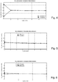
- the cyclic adsorption/ desorption performance is given in Fig. 4 .
- the BET surface area of the adsorbent was 16.5 m 2 /g, and the cyclic adsorption/ desorption performance is given in Fig. 5 .
- the BET surface area of the adsorbent was 29.8 m 2 /g, and the cyclic adsorption/ desorption performance is given in Fig. 6 .
- a mat-shaped adsorbent structure made from cellulose nanofibers is inserted into a flow-through container.
- the first process step adsorption
- the second process step desorption
- the container is evacuated to 1 - 250 mbar abs by a vacuum pump/vacuum line and the sorbent is heated to 50 - 110 °C during 5 - 240 minutes.
- the gas stream leaving the container is being sucked off by the vacuum pump/vacuum line (the "desorption stream") and contains 0.5 to 100% carbon dioxide, the remainder being air and/or water vapor.
- the air content of the desorption stream is caused by air remainders in the system volume after evacuation and air penetrating the container through leaks and/or intended openings during desorption.
- the sorbent is cooled down to desorption temperature and the next adsorption cycle is initiated.
Landscapes
- Chemical & Material Sciences (AREA)
- Analytical Chemistry (AREA)
- Chemical Kinetics & Catalysis (AREA)
- Organic Chemistry (AREA)
- Engineering & Computer Science (AREA)
- Nanotechnology (AREA)
- General Chemical & Material Sciences (AREA)
- Oil, Petroleum & Natural Gas (AREA)
- Materials Engineering (AREA)
- Crystallography & Structural Chemistry (AREA)
- Environmental & Geological Engineering (AREA)
- Biomedical Technology (AREA)
- Health & Medical Sciences (AREA)
- Composite Materials (AREA)
- Condensed Matter Physics & Semiconductors (AREA)
- General Physics & Mathematics (AREA)
- Physics & Mathematics (AREA)
- Solid-Sorbent Or Filter-Aiding Compositions (AREA)
Description
- The present invention generally relates to porous adsorbent structures for adsorption of CO2 from a gas mixture, to methods for producing such structures and to uses thereof.
- The capture of CO2 from gaseous mixtures has considerable potential for environmental protection, but also in economical terms. In particular, removal of CO2 from atmospheric air is considered to be an important and promising option in the portfolio of technologies to mitigate global climate change (see e.g.
WO 2010/091831 and references cited therein). - Amine modified solid sorbents are known to be suitable for CO2 capture from gas streams like flue gases or air (see e.g.
WO 2010/091831 and references cited therein). Generally amine modified solid sorbents describe a class of materials where amines are immobilized on a porous solid substrate, either through physisorption or covalent bonding. In the scientific and patent literature several different solid supports and amines have been investigated for CO2 capture. So far patents include silica (WO 2008/021700 ), carbonaceous materials (US 6547S54), polymeric materials (WO2008/131132 ,WO 2009/067625 ), natural fibers (WO 2009/067625 ,WO 2010/091831 ) and clay (US 6908497 ) as solid supports. - Although the efficiency of CO2 removal is an important factor, there are clearly further requirements to be fulfilled by a viable technology for CO2 removal from atmospheric air. Current estimates indicate that for each ton of captured CO2 at least 1 kg of adsorbent material is needed. Hence, in order to avoid large amounts of waste being created, it is highly desirable to find CO2 adsorbers that are not only efficient, but also made of biobased materials like natural fibers, as the latter stem from re-growing sources which can easily be recycled. One such biomaterial is cellulose, which has many advantages such as abundance, biodegradability, biocompatibility and a high surface area.
- Cellulose is obtained from plants in the form of fibers having a diameter of about 30 to 100 µm and a length of several millimeters. These cellulose fibers are composed of cellulose microfibrils with a diameter of 2 to 10 nm and a length of several tens of microns formed during biosynthesis in higher plants. The disintegration of cellulose fibers to microfibrils aggregates is well known and was first described in
US 4483743 . In the present invention, cellulose fibrils were produced that had a diameter of 4 nm to 1 µm and a length of 100 nm to 1 mm, which will be referred to as cellulose nanofibers hereinbelow. Occasionally, cellulose fibrils having a diameter of more than 1 µm were present in the product, which can be a desired property of the product described herein. In the literature several notations exist, which describe products having similar dimensions to the cellulose nanofibers described here, where the most important notations are nanofibrillated cellulose (abbreviated as NFC), microfibrillated cellulose (abbreviated as MFC), cellulose nanowhiskers and cellulose nanocrystals. - The modification of cellulose fibers having diameters in the micrometer range and cellulose nanofibers having a diameter from 4 nm to 1 µm and a length from 100 nm to 1 mm with aminosilanes is generally known, and several scientific and patent publications exist (e.g.
EP 2196478 ). - So far amine modified cellulose nanofibers have been used for composite structures (
WO 2010/066905 ) and as antimicrobial tissues. The state of the art preparation method for amine modified cellulose nanofibers is to immerse the aminosilane and cellulose nanofibers in an aqueous or alcoholic solution, stir the resulting mixture and filter the wet slurry. The wet slurry is then either oven or air dried. Thereby, non-porous, densely packed amine modified cellulose nanofiber films are created. These films are not appropriate for CO2 capture as the reactive amine sites are not accessible for the CO2 molecules. - In summary, although various methods and devices for capturing CO2 from gas mixtures are basically known, there is still a strong need for improved technical solutions.
- The above mentioned and further tasks are solved by the present invention, which provides methods as defined in
claims 1 and 3 for producing a porous adsorbent structure that is capable of a reversible adsorption and desorption cycle for capturing CO2 from a gas mixture. - The porous adsorbent structures comprise a support matrix of surface modified cellulose nanofibers, which surface modified cellulose nanofibers consist of cellulose nanofibers having a diameter of about 4 nm to about 1000 nm covered with a coupling agent being covalently bound to the surface thereof. The support matrix is a web of nanofibers with a porosity of at least 20%, preferably above 50%, even more preferably above 60%, where porosity is defined as the volume of the void over the total volume, and the coupling agent comprises at least one monoalkyldialkoxyaminosilane. The porous web of cellulose nanofibers can have the properties of an aerogel.
- Advantageous embodiments are defined in the dependent claims.
- As used herein, the general term "cellulose nanofiber" is defined as a cellulose fiber-like nanostructure with a diameter varying from about 4 to about 1000 nm, which includes, in particular but not exclusively, cellulose nanofibrils having a length of about 1 µm or more and cellulose nanowhiskers having a length of about 100 to 500 nm and a diameter below 10 nm.
- As is generally known, aerogels are solid materials with high porosity and surface area, low density and other interesting mechanical and non-mechanical properties. Aerogels made from cellulose have been known for some time, and prepared from NFC suspensions, from bacterial cellulose, from cellulose nanoparticles (
WO 2011/030170 ), from cellulose nanowhiskers and through dissolving cellulose. In analogy with the definitions used inWO 2011/ 030170 the term "aerogel" shall be understood here as an open porous structure with a porosity of at least 20%. However, the support matrices used in the present invention can be prepared with varying degrees of porosity above 20%, preferably above 50%, and even more preferably above 60%. They will generally have a BET (Brunauer-Emmett-Teller) surface area exceeding 2 m2/g, preferably more than 5 m2/g, and even more preferably more than 6 m2/g. - The cellulose nanofiber material used to prepare the nanofiber webs according to the present invention will often contain a certain amount of long fibers and/or larger diameter fibers, henceforth briefly called "large cellulose fibers". As used here, "large cellulose fibers" are defined as having a diameter in the range of more than 1 µm up to the diameter of the pristine plant fiber, i.e. 30 µm to 100 µm, and/or having a length exceeding 1 mm. However, a key requirement of the invention is the presence of a sufficiently large proportion of small cellulose nanofibers having a diameter not exceeding 1000 nm. From an operational point of view, the average diameter of the cellulose nanofibers shall be small enough so that suspending 2% w/w of the cellulose nanofiber material in water will form a hydrogel having a viscosity of at least 2000 mPa*s at a shear rate of 0.1 Hz.
- According to the invention, the coupling agent shall comprise at least one monoalkyldialkoxyaminosilane. This term shall be understood here to designate an aminofunctional silane compound with the general formula (I)
- It was surprisingly found that the application of the above defined monoalkyldialkoxyaminosilane to a porous support matrix formed as a web of cellulose nanofibers leads to an adsorbent structure with highly advantageous properties. Such adsorbent structure is capable of a reversible adsorption and desorption cycle for capturing CO2 from a gas mixture. In particular, it was found that monoalkyldialkoxyaminosilanes give substantially better results than the trialkoxyaminosilanes used in the prior art. A key feature of the present invention is the presence of monoalkyldialkoxyaminosilane.
- Although patent documents
JP 2008 2666630 A EP 2196478 both disclose some type of structure containing cellulose nanofibers partially covered by a monoalkyldialkoxyaminosilane, they do not refer to the task of CO2 adsorption and the related key feature of using a monoalkyldialkoxysilane. They do not disclose any specific method steps aimed at producing a highly porous structure as in the present invention. Rather than that, they generally seek to provide materials with improved mechanical properties. - The adsorbent structures produced according to the present invention have good recyclability, i.e. they can be subjected to a large number of CO2 adsorption/desorption cycles without any substantial loss of performance. Moreover, they operate in a dry state, i.e. unlike some previously disclosed adsorbent structures they do not require wetting with a liquid able to react with CO2.
- Advantageously, the adsorbent structures are used for removing CO2 from ambient air. It is contemplated that the adsorbent structures may also be used for other reactive species such as SO2.
- Basic processes that can be used for the removal of CO2 from ambient air have been described in
WO 2010/091831 A1 . In a typical adsorption process, ambient air is passed at an appropriate flow velocity through the adsorbent material, which is configured e.g. as a mat-like structure, thereby loading the adsorbent material with CO2.Thereafter, the structure can be regenerated, i.e. the adsorbed CO2 can be released again, through a temperature increase and/or a pressure reduction. The necessary heat can be added to the structure via any form of heat exchanger, a gas or also by direct or indirect solar irradiation. During the regeneration process a suitable construction like shutters, multiple layers of perforated plates, a cylindrical structure that is covered with a lid etc. keeps the adsorbent structure isolated from the environment in order to capture the released CO2 and conduct it out of the system. - In the use of the adsorbent structures produced according to the invention, there is provided a process for removing CO2 from ambient air, which process comprises the steps of:
- a) providing a porous adsorbent structure as defined further above;
- b) establishing a flow of ambient air through said adsorbent structure, thereby loading the adsorbent material with CO2 ;
- c) interrupting said flow;
- d) regenerating said adsorbent structure by releasing the CO2 adsorbed thereto; and
- e) optionally repeating steps b) to d) as required.
- It will be understood that said regenerating step d) may be carried out "offline", i.e. by removing said adsorbent structure and taking the same to a suitable regeneration device. To this end it may be useful to utilize a plurality of adsorbent structures so as to avoid extended process interruption time.
- According to one aspect, there is provided a method for producing a porous adsorbent structure as defined above, which method comprises the steps of:
- a) providing a first amount of a homogenized suspension of cellulose nanofibers having a diameter of about 4 nm to about 1000 nm and a length of 100 nm to 1 mm in a solvent;
- b) adding thereto a second amount of a coupling agent comprising at least one monoalkyldialkoxyaminosilane, thereby allowing formation of a homogeneous suspension of surface modified cellulose nanofibers in said solvent;
- c) mechanically concentrating said suspension through centrifugation, filtration or pressing, thereby obtaining a wet slurry;
- d) optionally washing said wet slurry with said solvent;
- e) removing said solvent by a drying operation, said drying operation being selected from freeze drying, atmospheric freeze drying, or a combination thereof, preferably freeze drying, thereby obtaining a dried material; and
- f) subjecting said dried material to a heating process in an inert atmosphere, thereby obtaining said porous adsorbent structure.
- The above defined method starts with a homogenized suspension of cellulose nanofibers, which may be obtained by various known means, to which is added the selected coupling agent. The choice of solvent will depend on various factors, including the selected coupling agent, the hydrolysis of the selected coupling agent, the drying method, environmental considerations and economics. In many applications it will be preferable to use an aqueous medium, particularly deionized water. In one embodiment, the aqueous medium is acidified, preferably with acetic acid or CO2.In a particularly preferred embodiment, the aqueous medium is acidified with CO2.
- In order to avoid an unacceptable loss of porosity, it is essential that the removal of the solvent be carried out by a method that does not cause a collapse of the porous structure. Accordingly, the solvent is removed by freeze drying, atmospheric freeze drying, air drying, vacuum drying, heating or a combination thereof, preferably freeze drying.
- According to a further aspect, there is provided a method for producing a porous adsorbent structure as defined above, said support matrix further comprising an admixture of large cellulose fibers, said large cellulose fibers having a diameter of more than 1 µm and/or a length exceeding 1 mm, the method comprising the steps of:
- a) providing a first amount of a homogenized suspension of cellulose nanofibers having a diameter of about 4 nm to about 1000 nm and a length of 100 nm to 1 mm in a solvent, wherein said homogenized suspension of cellulose nanofibers further comprises an admixture of large cellulose fibers, said large cellulose fibers having a diameter of more than 1 µm and/or a length exceeding 1 mm;
- b) adding thereto a second amount of a coupling agent comprising at least one monoalkyldialkoxyaminosilane, thereby allowing formation of a homogeneous suspension of surface modified cellulose nanofibers in said solvent;
- c) mechanically concentrating said suspension through centrifugation, filtration or pressing, thereby obtaining a wet slurry;
- d) optionally washing said wet slurry with said solvent;
- e) removing said solvent by air drying at room temperature, thereby obtaining a dried material; and
- f) subjecting said dried material to a heating process in an inert atmosphere, thereby obtaining said porous adsorbent structure.
- As already mentioned above, the choice of solvent will depend on various factors, including the selected coupling agent, the hydrolysis of the selected coupling agent, the drying method, environmental considerations and economics. In many applications of this further method it will be preferable to use ethanol.
- The optional washing step d) and e), respectively, in the above defined methods allows recuperation of not adsorbed coupling agent and thus contributes to an economically and ecologically improved process.
- In many embodiments, the coupling agent comprises just one monoalkyldialkoxyaminosilane. However, the invention is not limited to such cases, and it may actually be advantageous if the coupling agent comprises at least one further monoalkyldialkoxyaminosilane.
- The compound class of monoalkyldialkoxyaminosilanes as defined above comprises a large number of compounds. It is generally understood that the two alkoxy groups R1O and R2O,which preferably are identical, e.g. two methoxy or two ethoxy groups, provide the functionality for covalent coupling to the cellulose nanofiber structure. This bonding takes place by hydrolysis of the alkoxy-group(s), followed by the condensation of the generated silanol groups with the hydroxyl-groups on the surface of the nanofibers. In contrast, the alkyl group R3 will generally act as an inert moiety in the present application context. The amine group, on the other hand, plays an important role for the capture of CO2 molecules. For the intended purpose of the present invention it is important that the amine group of the covalently bound silane agent remains free to react with CO2, whereas a bonding of the amine moiety to the cellulose nanofibers is considered to be undesirable. Using a coupling agent predominantly comprising one or more monoalkyldialkoxyaminosilanes according to the present invention leads to surprisingly good results in terms of overall performance of the adsorbent structure. Without being bound by theory, it appears that these advantageous effects are related to the fact that monoalkyldialkoxyaminosilanes on the one hand do not form any 3-dimensional polysiloxanes but on the other hand are capable of forming the required porous adsorbent structure by forming linear structures.
- In a preferred embodiment, each one of the monoalkyldialkoxyaminosilane is selected from the group consisting of:
- 3-aminopropylmethyldiethoxysilane,
- N-(2-Aminoethyl)-3-aminopropyl-methyldimethoxysilane, and
- N-(3-Methyldimethoxysilylpropyl)diethylenetriamine.
- The first compound, 3-aminopropylmethyldiethoxysilane (CAS 3179-76-8), is a monoamine functional silane with the reactive amine group located at the distal end of the propyl substituent. The second compound, N-(2-Aminoethyl)-3-aminopropyl-methyldimethoxysilane (CAS 3069-29-2), is a diamine functional silane wherein one of the hydrogens of the reactive amine group of the above mentioned first compound is replaced by an aminoethyl group. The third compound, N-(3-Methyldimethoxysilylpropyl)diethylenetriamine, is a triamine functional silane wherein one of the hydrogens of the reactive amine group of the above mentioned second compound is replaced by an aminoethyl group. The first two compounds can be purchased whereas the third compound can be synthesized by known methods.
- In a further embodiment, the coupling agent further comprises a trialkoxyaminosilane in an amount of up to 60% by weight with respect to the total coupling agent weight. The term "trialkoxyaminosilane" shall be understood here to designate an aminofunctional silane compound with the general formula (II)

- This also includes mixtures of trialkoxysilanes, in which case the total amount of trialkoxyaminosilanes shall not exceed the above mentioned 60% limit. In a further embodiment, the coupling agent further comprises a trialkoxyaminosilane in an amount of up to 25% by weight with respect to the total coupling agent weight.
- In a specific embodiment, the trialkoxyaminosilane(s) is/are selected from the group consisting of:
- 3-aminopropyltriethoxysilane (CAS 919-30-2),
- 3-aminopropyltrimethoxysilane (CAS 13822-56-5),
- N-(2-Aminoethyl)-3-aminopropyl-trimethoxysilane (CAS 1760-24-3),
- N-(2-Aminoethyl)-3-aminopropyl-triethoxysilane (CAS 5089-72-5), and
- N-(3-Trimethoxysilylpropyl)diethylenetriamine (CAS 35141-30-1).
- For many practical applications, it is preferable for the adsorbent structure to further comprise a reinforcing structure. Such reinforcing structures may have a variety of configurations depending on the application. For example, they may be formed by an admixture of long reinforcing fibers or by a honeycomb structure. In one embodiment, a reinforcing fiber mat is used to form CO2 adsorber panels of approximately A4-size (i.e. approximately 21 x 30 cm) or 15 x 15 cm, but of course any other sizes are possible.
- While freeze drying methods comprising vacuum freeze drying and atmospheric freeze drying readily work with any cellulose nanofiber material as defined further above, this is not always the case for non-freeze drying methods such as air drying. Surprisingly, air drying was found to produce comparatively low porosity structures when using high-quality cellulose nanofiber material having only small amounts of large cellulose fibers. Therefore, an economically and ecologically advantageous embodiment of the invention relies on using lower quality cellulose nanofiber material having an appreciable admixture of large cellulose fibers and applying a non-freeze drying method.
- The above mentioned and other features and objects of this invention and the manner of achieving them will become more apparent and this invention itself will be better understood by reference to the following description of various embodiments of this invention taken in conjunction with the accompanying drawings. Each figure shows the CO2 adsorption/desorption mass balance for a certain number of cycles under specified adsorption and desorption conditions, which include the gas medium and flow rate, the temperature, the relative humidity (RH) expressed at a given temperature and the cycle time. In all these measurements the desorbed amount in the first cycle was higher than the adsorbed amount in the first cycle, which was particularly pronounced in the measurements of
Fig. 2 andFig. 4 . This effect is attributed to the fact that the samples were stored in ambient air for a certain time before starting the experiments and thus had already adsorbed a certain quantity of CO2.. - Fig. 1
- Example 3, adsorbent mass 0.8 g,
Adsorption: 1l/min air, 25°C, RH 0% @ 25°C, 60min,
Desorption: 0.8l/min argon, 90°C, RH 0% @ 25°C, 30min; - Fig. 2
- Example 3, adsorbent mass 0.8 g,
Adsorption: 1l/min air, 25°C, RH 40% @ 25°C, 60min,
Desorption: 0.8l/min argon, 90°C, RH 0% @ 25°C, 60min; - Fig. 3
- Example 5, adsorbent mass 1.2 g,
Adsorption: 1l/min air, 25°C, RH 40% @ 25°C, 60min,
Desorption: 0.8l/min argon, 90°C, RH 40% @ 25°C, 60min; - Fig. 4
- Example 8, adsorbent mass 1.1 g,
Adsorption: 1l/min air, 25°C, RH 40% @ 25°C, 60min,
Desorption: 0.8l/min argon, 90°C, RH 40% @ 25°C, 45min; - Fig. 5
- Example 9, adsorbent mass 0.8 g,
Adsorption: 1l/min air, 25°C, RH 40% @ 25°C, 60min,
Desorption: 0.8l/min argon, 90°C, RH 40% @ 25°C, 60min; - Fig. 6
- Example 10, adsorbent mass 1.0 g,
Adsorption: 1l/min air, 25°C, RH 40% @ 25°C, 60min,
Desorption: 0.8l/min argon, 90°C, RH 40% @ 25°C, 60min. - The time required to reach the maximum CO2 capture capacity under the above conditions is typically in the order of 12 hours, which is clearly longer than the above indicated adsorption time of 60 min. However, using shorter cycles in the order of 1 h will often be more viable from an industrial scale process. Therefore, the results presented in the figures are considered important indicators for the practical performance of the investigated systems.
- 1.2 kg refined fibrous beech wood pulp suspension having a dry material content of 13.5% w/w (Arbocel P10111 obtained from Rettenmeier & Söhne GmbH & Co. KG, Germany) was placed in a 10 liter thermostatic glass reactor kept at 15ºC and diluted with 8.8 kg of deionized water. The starting material is considered as a mixture of cellulose nanofibers and large cellulose fibers. The resulting suspension was stirred at 148 rpm for 21 h to allow swelling. Thereafter the suspension was homogenized for 170 min through an inline Ultra-Turrax system (Megatron MT 3000, Kinematica AG, Switzerland) at 15'000 rpm, which was connected to the glass reactor. The homogenized suspension was subjected to high shearing-stress generated through a high-shear homogenizer (Microfluidizer Type M-110Y, Microfluidics Corporation, USA). Thereby the suspension was pumped for 10 passes through a sequence of 400 µm and 200 µm interaction chambers and subsequently for 5 passes through a sequence of 200 µm and 75 µm interaction chambers at a flow rate of 9.75 g/s.
- Water was removed from the cellulose nanofiber suspension obtained according to Example 1 through centrifugation at 3'600 rpm for 20 min and subsequent freeze drying. For freeze drying, 25 ml of solution were poured in a copper cylinder, having a diameter of 40 mm. The copper cylinder was then immersed in liquid nitrogen and the frozen sample was dried in a freeze dryer without heating and/or cooling.
- 0.96g of 3-aminoproplymethyldiethoxysilane were hydrolyzed in 7.5g of demineralized water for 2h under stirring. To 25 g of cellulose nanofibers having a dry mass content of 3.2 % w/w in a beaker, the hydrolyzed silane-H2O mixture was added and completed with demineralized water to 40.8g. The resulting mixture was homogenized for 5 min at 12'000 rpm using an Ultra-Turrax blender device. The homogenized mixture was stirred for 2h. Thereafter the mixture was poured in a copper form that was immersed in liquid nitrogen. The frozen mixture was dried for 48 h in a freeze dryer. After freeze drying the sample was thermally treated at 120ºC in an argon atmosphere.
- The porous structure thus produced had a CO2 capture capacity of 1.15 mmol CO2/g adsorbent and a CO2 uptake rate of around 10 µmol CO2/g adsorbent/min during the first 60 min of CO2 adsorption. The BET surface was 22.9 m2/g. The cyclic adsorption/desorption performance is given in
Figs. 1 and 2 for two different conditions, namely adsorption of dry air and a short desorption cycle inFig. 1 , and adsorption of humid air and a longer desorption cycle inFig. 2 . - In a variant of the procedure described in Example 3, the solution was poured into a tray-like copper mold in which a reinforcing web of polyurethane fibers with a mesh size of 10 mm had been laid out. This was followed by freeze drying as in
Section 2. - 1 g of a dry porous cellulose nanofiber web product as obtained according to Example 2 was immersed in a solution containing 4 g of 3-aminopropylmethyldiethoxysilane in 100 g ethanol and kept for 24 h. Subsequently, the solution was removed by filtering and the resulting residue was dried in air so as to obtain a silane coated cellulose nanofiber specimen. This specimen was cured at 120°C for 2 h in an inert atmosphere, thereby yielding a porous adsorbent structure.
- The CO2 uptake rate was 10 µmol CO2/g adsorbent/min during the first 60 min of CO2 adsorption. The BET surface area was 8.8 m2/g. The cyclic adsorption/ desorption performance is given in
Fig. 3 . - 3.09 g of N-(2-Aminoethyl)-3-aminopropyl-methyldimethoxysilane were hydrolyzed in 7.5 g of demineralized H2O for 2h under stirring. 6 g of refined fibrous beech wood pulp suspension as described in Example 1 (13.5% w/w) was solvent exchanged (3 times) with an EtOH/H2O mixture (95/5, w/w), with ultra turrax homogenization for 1 min before each exchange.
The solvent exchanged cellulose nanofibers, the silane-H2O mixture and 142.5 g of EtOH were transferred to a beaker and were completed to 162 g with an EtOH/H2O mixture (95/5, w/w). - The resulting mixture was blended with an ultra turrax for 1 min, thereafter stirred for 2 h and then poured completely on a Nutsche filter (0=11 cm) and filtered by gravitation. The retentate was dried at room temperature for several days and subsequently cured at 60°C for 3 h. The porous structure thus produced had a CO2 capture capacity of 1.1 mmol CO2/g adsorbent.
- For the present and the following examples, the experimental procedure is given in a short list form.
- Into a beaker 46.2 g of cellulose nanofiber suspension (@ 3.2 wt. %) were added and completed with demineralized H2O to 288g
- Ultra turraxed for several minutes between 12k and 17k rpm
- Added 12g of 3-aminopropyltriethoxysilane
- Stirred mixture for 24 h at 500 rpm
- Centrifuged for 20 min @3600 rpm
- Frozen in liquid N2
- Evacuated frozen sample in freeze drier for 48 h
- Cured at 120°C for 2 h in Argon
- The CO2 capture capacity after 12 h of CO2 exposure was 0.32 mmol/g, and the BET surface area was 15.9 m2/g.
-
- Into a beaker were added 46.2 g of cellulose nanofiber suspension (@ 3.2 wt. %) and completed with demineralized H2O to 288 g
- Ultra turraxed for several minutes between 12k and 17k rpm
- Added 12 g of 3-aminopropylmethyldiethoxysilane
- Stirred mixture for 24 h at 500 rpm
- Centrifuged for 20 min @ 3600 rpm
- Frozen in liquid N2
- Evacuated frozen sample in freeze drier for 48 h
- Cured at 60°C for 180 minutes
- The CO2 capture capacity after 12 h of CO2 exposure was 1.277 mmol/g and the BET surface area was 9.6 m2/g. The cyclic adsorption/ desorption performance is given in
Fig. 4 . -
- Into a beaker were added 46.2 g of cellulose nanofiber suspension (@ 3.2 wt. %) and completed with demineralized H2O to 288 g
- Ultra turraxed for several minutes between 12k and 17k rpm
- Started bubbling 100% CO2 until the pH reached a value of roughly 3.8
- Added 6 g of 3-aminopropylmethyldiethoxysilane step by step so that pH never exceeded 7
- Stirred mixture for 24 h at 500 rpm under bubbling of CO2
- Centrifuged for 20 min @ 3600 rpm
- Frozen in liquid N2
- Evacuated frozen sample in freeze drier for 48 h
- Cured at 120°C for 2 h in argon
- The BET surface area of the adsorbent was 16.5 m2/g, and the cyclic adsorption/ desorption performance is given in
Fig. 5 . -
- Into a beaker were added 46.2 g of cellulose nanofiber suspension (@ 3.2 wt. %) and completed with demineralized H2O to 294 g
- Ultra turraxed for several minutes between 12k and 17k rpm
- Added 6 g of 3-aminopropylmethyldiethoxysilane
- Stirred mixture for 24 h at 500 rpm
- Centrifuged for 20 min @ 3600 rpm
- Frozen in liquid N2
- Evacuated frozen sample in freeze drier for 48 h
- Cured at 120°C for 2 h in argon atmosphere
- The BET surface area of the adsorbent was 29.8 m2/g, and the cyclic adsorption/ desorption performance is given in
Fig. 6 . -
- Hydrolyzed 2.87 g of 3-aminopropylmethyldiethoxysilane in 7.5 g of demineralized H2O for 2 h under stirring
- Solvent exchanged 6 g of refined fibrous beech wood pulp (13.5% w/w) with EtOH/H2O mixture (95/5, w/w) 3 times (ultra turraxed 1 min before each exchange)
- Into a beaker were added 142.5 g of EtOH, the solvent exchanged cellulose nanofibers containing an admixture of large cellulose fibers, the silane-H2O mixture and completed with a EtOH/H2O mixture (95/5, w/w) to 162 g
- Ultra turraxed for 1 min
- Stirred mixture for 2 h
- Poured solution completely on Nutsche filter
- Filtered by gravitation and dried at room temperature for several days
- Cured at 60°C for 3 h
-
- Hydrolyzed 0.76 g of 3-aminopropyltrimethoxysilane and 2.15 g of 3-aminopropylmethyldiethoxysilane in 7.5 g of demineralized H2O for 2 h under stirring
- Solvent exchanged 6 g of refined fibrous beech wood pulp (13.5% w/w) with EtOH/H2O mixture (95/5, w/w) 3 times (ultra turraxed 1min before each exchange)
- Into a beaker were added 142.5 g of EtOH, the solvent exchanged cellulose nanofibers containing an admixture of large cellulose fibers , the silane-H2O mixture and completed with a EtOH/H2O mixture (95/5, w/w) to 162 g
- Ultra turraxed for 1 min
- Stirred mixture for 2h
- Poured solution completely on Nutsche filter
- Filtered by gravitation and dried at room temperature for several days
- Cured at 60°C for 3 h
-
- Added 2.87 g of 3-aminopropyldiethoxysilane to sealable glass bottle and completed with H2O to 71.75 g and left closed for roughly 1 week
- Into a beaker were added 6 g of refined fibrous beech wood pulp (13.5% w/w) the hydrolyzed silane solution and completed with H2O to 162 g
- Ultra turraxed for 1 min
- Stirred mixture for 2h
- Poured solution on Nutsche filter
- Filtered by gravitation and dried at room temperature for several days
- Cured at 60°C for 3 h
-
- Into a beaker were added 120.84 g of cellulose nanofiber suspension (@ 1.2 wt. %) and completed with demineralized H2O to 288 g
- Ultra turrax for several minutes between 12k and 17k rpm
- Add 12 g of 3-aminopropylmethyldiethoxysilane
- Stir mixture for 24 h at 500 rpm
- Centrifuge for 20 min @ 3600 rpm
- Freeze in liquid N2
- Evacuate freezed sample in freeze drier for 48h
- Cure at 120°C for 2 h in an inert atmosphere
-
- Into a beaker were added 120.84 g of cellulose nanofiber suspension (@ 1.2 wt. %) and completed with demineralized H2O to 288 g
- Ultra turrax for several minutes between 12k and 17k rpm
- Add 12 g of 3-aminopropylmethyldiethoxysilane
- Stir mixture for 24 h at 500 rpm
- Poured solution on Nutsche filter
- Filtered by gravitation and dried at room temperature for several days
- Cure at 120°C for 2 h in an inert atmosphere
- A mat-shaped adsorbent structure made from cellulose nanofibers is inserted into a flow-through container. During the first process step (adsorption) it is exposed to an air flow for 0.1 to 24 hours at -10 - 40 °C and atmospheric pressure (0.7 to 1.3 barabs). During this time, CO2 or CO2 and water vapor is adsorbed by the sorbent structure from the air stream. In the following, the second process step (desorption) is initiated and the container is evacuated to 1 - 250 mbarabs by a vacuum pump/vacuum line and the sorbent is heated to 50 - 110 °C during 5 - 240 minutes. The gas stream leaving the container is being sucked off by the vacuum pump/vacuum line (the "desorption stream") and contains 0.5 to 100% carbon dioxide, the remainder being air and/or water vapor. The air content of the desorption stream is caused by air remainders in the system volume after evacuation and air penetrating the container through leaks and/or intended openings during desorption. After completion of the desorption step, the sorbent is cooled down to desorption temperature and the next adsorption cycle is initiated.
Claims (6)
- A method for producing a porous adsorbent structure that is capable of a reversible adsorption and desorption cycle for capturing CO2 from a gas mixture, said structure comprising a support matrix of surface modified cellulose nanofibers, said surface modified cellulose nanofibers consisting of cellulose nanofibers having a diameter of 4 nm to 1000 nm and a length of 100 nm to 1 mm covered with a coupling agent being covalently bound to the surface thereof, whereini) said support matrix is a web of nanofibers with a porosity of at least 20%, andii) said coupling agent comprises at least one monoalkyldialkoxyaminosilane,the method comprising the steps of:a) providing a first amount of a homogenized suspension of cellulose nanofibers having a diameter of 4 nm to 1000 nm and a length of 100 nm to 1 mm in a solvent;b) adding thereto a second amount of a coupling agent comprising at least one monoalkyldialkoxyaminosilane, thereby allowing formation of a homogeneous suspension of surface modified cellulose nanofibers in said solvent;c) mechanically concentrating said suspension through centrifugation, filtration or pressing, thereby obtaining a wet slurry;d) optionally washing said wet slurry with said solvent;e) removing said solvent by a drying operation, said drying operation being selected from freeze drying, atmospheric freeze drying or a combination thereof, preferably freeze drying, thereby obtaining a dried material; andf) subjecting said dried material to a heating process in an inert atmosphere, thereby obtaining said porous adsorbent structure.
- The method according to claim 1, wherein said solvent is an aqueous medium which is preferably acidified, preferably with acetic acid or CO2,more preferably with CO2.
- A method for producing a porous adsorbent structure that is capable of a reversible adsorption and desorption cycle for capturing CO2 from a gas mixture, said structure comprising a support matrix of surface modified cellulose nanofibers, said surface modified cellulose nanofibers consisting of cellulose nanofibers having a diameter of 4 nm to 1000 nm and a length of 100 nm to 1 mm covered with a coupling agent being covalently bound to the surface thereof, whereini) said support matrix is a web of nanofibers with a porosity of at least 20%, andii) said coupling agent comprises at least one monoalkyldialkoxyaminosilane,said support matrix further comprising an admixture of large cellulose fibers, said large cellulose fibers having a diameter of more than 1 µm and/or a length exceeding 1 mm
the method comprising the steps of:a) providing a first amount of a homogenized suspension of cellulose nanofibers having a diameter of 4 nm to about 1000 nm and a length of 100 nm to 1 mm in a solvent, wherein said homogenized suspension of cellulose nanofibers further comprises an admixture of large cellulose fibers, said large cellulose fibers having a diameter of more than 1 µm and/or a length exceeding 1 mm;b) adding thereto a second amount of a coupling agent comprising at least one monoalkyldialkoxyaminosilane, thereby allowing formation of a homogeneous suspension of surface modified cellulose nanofibers in said solvent;c) mechanically concentrating said suspension through centrifugation, filtration or pressing, thereby obtaining a wet slurry;d) optionally washing said wet slurry with said solvent;e) removing said solvent by air drying at room temperature, thereby obtaining a dried material; andf) subjecting said dried material to a heating process in an inert atmosphere, thereby obtaining said porous adsorbent structure. - The method according to any one of claims 1 to 3, wherein each one of said monoalkyldialkoxyaminosilanes is selected from the group consisting of:- 3-aminopropylmethyldiethoxysilane,- N-(2-Aminoethyl)-3-aminopropyl-methyldimethoxysilane, and- N-(3-Methyldimethoxysilylpropyl)diethylenetriamine.
- The method according to any one of claims 1 to 4, wherein said coupling agent further comprises a trialkoxyaminosilane in an amount of up to 60% by weight with respect to the total coupling agent weight.
- The method according to claim 5, wherein said trialkoxyaminosilane is selected from the group consisting of:- 3-aminopropyltriethoxysilane,- 3-aminopropyltrimethoxysilane,- N-(2-Aminoethyl)-3-aminopropyl-trimethoxysilane,- N-(2-Aminoethyl)-3-aminopropyl-triethoxysilane, and- N-(3-Trimethoxysilylpropyl)diethylenetriamine.
Priority Applications (1)
| Application Number | Priority Date | Filing Date | Title |
|---|---|---|---|
| EP12725832.5A EP2717992B1 (en) | 2011-06-06 | 2012-06-06 | Porous adsorbent structure for adsorption of co2 from a gas mixture |
Applications Claiming Priority (3)
| Application Number | Priority Date | Filing Date | Title |
|---|---|---|---|
| EP20110168838 EP2532410A1 (en) | 2011-06-06 | 2011-06-06 | Porous adsorbent structure for adsorption of CO2 from a gas mixture |
| PCT/EP2012/060778 WO2012168346A1 (en) | 2011-06-06 | 2012-06-06 | Porous adsorbent structure for adsorption of co2 from a gas mixture |
| EP12725832.5A EP2717992B1 (en) | 2011-06-06 | 2012-06-06 | Porous adsorbent structure for adsorption of co2 from a gas mixture |
Publications (2)
| Publication Number | Publication Date |
|---|---|
| EP2717992A1 EP2717992A1 (en) | 2014-04-16 |
| EP2717992B1 true EP2717992B1 (en) | 2021-08-11 |
Family
ID=46208598
Family Applications (2)
| Application Number | Title | Priority Date | Filing Date |
|---|---|---|---|
| EP20110168838 Withdrawn EP2532410A1 (en) | 2011-06-06 | 2011-06-06 | Porous adsorbent structure for adsorption of CO2 from a gas mixture |
| EP12725832.5A Active EP2717992B1 (en) | 2011-06-06 | 2012-06-06 | Porous adsorbent structure for adsorption of co2 from a gas mixture |
Family Applications Before (1)
| Application Number | Title | Priority Date | Filing Date |
|---|---|---|---|
| EP20110168838 Withdrawn EP2532410A1 (en) | 2011-06-06 | 2011-06-06 | Porous adsorbent structure for adsorption of CO2 from a gas mixture |
Country Status (4)
| Country | Link |
|---|---|
| US (2) | US20140134088A1 (en) |
| EP (2) | EP2532410A1 (en) |
| CN (1) | CN103702740B (en) |
| WO (1) | WO2012168346A1 (en) |
Families Citing this family (59)
| Publication number | Priority date | Publication date | Assignee | Title |
|---|---|---|---|---|
| IN2014KN02636A (en) * | 2012-07-13 | 2015-05-08 | Sappi Netherlands Services Bv | |
| AU2013291997A1 (en) * | 2012-07-17 | 2015-01-29 | Antecy B.V. | Method for accelerating growth of plants in a controlled environment |
| GB201215380D0 (en) | 2012-08-29 | 2012-10-10 | Ccm Res Ltd | Methods and compositions |
| WO2014033456A1 (en) * | 2012-08-29 | 2014-03-06 | Ccm Research Limited | Method and compositions for capturing carbon dioxide |
| GB2505437A (en) * | 2012-08-29 | 2014-03-05 | Ccm Res Ltd | A method of affixing carbon dioxide onto the surface of a cellulosic material |
| CN105163830B (en) * | 2013-04-18 | 2018-01-09 | 克莱姆沃克斯有限公司 | Low pressure drop configuration of particulate adsorption bed for adsorptive gas separation process |
| US11007470B2 (en) | 2013-04-18 | 2021-05-18 | Climeworks Ag | Low-pressure drop structure of particle adsorbent bed for improved adsorption gas separation process |
| US10427086B2 (en) | 2013-04-18 | 2019-10-01 | Climeworks Ag | Low-pressure drop structure of particle adsorbent bed for adsorption gas separation process |
| WO2018083109A1 (en) | 2016-11-04 | 2018-05-11 | Climeworks Ag | Low-pressure drop structure of particle adsorbent bed for improved adsorption gas separation process |
| WO2014208917A2 (en) * | 2013-06-25 | 2014-12-31 | 동국대학교 산학협력단 | Holocellulose aerogel and heavy metal adsorbent using same |
| US10350576B2 (en) * | 2013-10-29 | 2019-07-16 | Wisconsin Alumni Research Foundation | Sustainable aerogels and uses thereof |
| CN106488795B (en) | 2014-06-03 | 2020-03-13 | 克莱姆沃克斯有限公司 | Direct air capture device |
| WO2016005226A1 (en) | 2014-07-10 | 2016-01-14 | Climeworks Ag | Steam assisted vacuum desorption process for carbon dioxide capture |
| EP3023455A1 (en) | 2014-11-21 | 2016-05-25 | Fundacíon Tecnalia Research & Innovation | Porous cellulosic materials and process for their preparation |
| CN105032364B (en) * | 2015-07-02 | 2018-01-05 | 南京林业大学 | The method that carbon dioxide absorbing material is manufactured with fast growing wood |
| EP3319998B1 (en) * | 2015-07-10 | 2023-08-16 | Climeworks AG | Amine-functionalized fibrillated cellulose for co2 adsorption and methods for making same |
| CN115069062A (en) | 2016-11-23 | 2022-09-20 | 天空树公司 | Improved method and apparatus for reversible adsorption of carbon dioxide |
| WO2018099709A1 (en) | 2016-11-29 | 2018-06-07 | Climeworks Ag | Methods for the removal of co2 from atmospheric air or other co2-containing gas in order to achieve co2 emissions reductions or negative co2 emissions |
| AU2017383560B2 (en) | 2016-12-23 | 2023-05-25 | Carbon Engineering Ltd. | Method and system for synthesizing fuel from dilute carbon dioxide source |
| WO2018210617A1 (en) | 2017-05-15 | 2018-11-22 | Climeworks Ag | Improved low-pressure drop structure of particle adsorbent bed for adsorption gas separation process |
| KR102688429B1 (en) | 2017-08-31 | 2024-07-26 | 킴벌리-클라크 월드와이드, 인크. | Nanofibrillated cellulose fiber |
| WO2019092127A1 (en) | 2017-11-10 | 2019-05-16 | Climeworks Ag | Materials for the direct capture of carbon dioxide from atmospheric air |
| JP2019136669A (en) * | 2018-02-13 | 2019-08-22 | 真庭バイオケミカル株式会社 | Adsorbent and method for producing the same |
| AU2019284807A1 (en) | 2018-06-14 | 2020-10-15 | Climeworks Ag | Method and device for adsorption/desorption of carbon dioxide from gas streams with heat recovery unit |
| JP7089178B2 (en) * | 2018-07-23 | 2022-06-22 | ダイキン工業株式会社 | Total heat exchange element and its manufacturing method |
| WO2020039452A1 (en) * | 2018-08-20 | 2020-02-27 | INDIAN INSTITUTE OF TECHNOLOGY MADRAS (IIT Madras) | An enhanced carbon dioxide sorbent nanofiber membrane and a device thereof |
| WO2021099695A1 (en) | 2019-11-19 | 2021-05-27 | Arkolia Energies | Plant for producing methane |
| CN110818287A (en) * | 2019-12-30 | 2020-02-21 | 衢州顺天钙业有限公司 | Preparation method of high-dispersity and high-specific-surface-area calcium hydroxide |
| US11420150B2 (en) | 2020-02-21 | 2022-08-23 | King Fahd University Of Petroleum And Minerals | Aminated magnesium oxide adsorbent and a method of capturing carbon dioxide |
| US20230201759A1 (en) | 2020-05-27 | 2023-06-29 | Climeworks Ag | Methods and devices for steam driven carbon dioxide capture |
| EP4157485A1 (en) | 2020-05-27 | 2023-04-05 | Climeworks AG | Atmospheric steam desorption for direct air capture |
| EP4157484A1 (en) | 2020-05-29 | 2023-04-05 | Climeworks AG | Method for capture of carbon dioxide from ambient air and corresponding adsorber structures with a plurality of parallel surfaces |
| KR20230029806A (en) * | 2020-06-22 | 2023-03-03 | 클라임웍스 아게 | Method and device for direct air capture of carbon dioxide using a solid polymer support material functionalized with amino functional groups, and use of the material for capture of carbon dioxide from air |
| WO2022013197A1 (en) | 2020-07-16 | 2022-01-20 | Climeworks Ag | Amino sorbents for capturing of co2 from gas streams |
| US20240001281A1 (en) | 2020-12-18 | 2024-01-04 | Climeworks Ag | Improved materials for direct air capture and uses thereof |
| US20240335816A1 (en) | 2021-07-21 | 2024-10-10 | Climeworks Ag | Amine functionalized fibres for direct air capture |
| EP4433204A1 (en) | 2021-11-19 | 2024-09-25 | Climeworks AG | Regeneration of degraded amino-sorbents for carbon capture |
| CA3237327A1 (en) | 2021-11-25 | 2023-06-01 | Angelo VARGAS | Sorbent material for co2 capture, uses thereof and methods for making same |
| WO2023104656A1 (en) | 2021-12-09 | 2023-06-15 | Climeworks Ag | Method for separating gaseous carbon dioxide from a gas mixture |
| AU2022409237A1 (en) | 2021-12-16 | 2024-06-27 | Climeworks Ag | Co2 adsorption system and method for co2 adsorption using humidity stable polystyrene-divinylbenzene amine functionalized polymeric adsorbents |
| JP2023171049A (en) * | 2022-05-20 | 2023-12-01 | 関西熱化学株式会社 | Porous adsorbent and its manufacturing method |
| WO2024002881A1 (en) | 2022-06-28 | 2024-01-04 | Climeworks Ag | Sorbent materials for co2 capture, uses thereof and methods for making same |
| WO2024002882A1 (en) | 2022-06-29 | 2024-01-04 | Climeworks Ag | Sorbent materials for co2 capture, uses thereof and methods for making same |
| WO2024006506A1 (en) | 2022-07-01 | 2024-01-04 | W. L. Gore & Associates, Inc. | Structure with external support for particle adsorbent bed for adsorption gas separation process |
| EP4572875A1 (en) | 2022-08-15 | 2025-06-25 | W. L. Gore & Associates, Inc. | Structures and methods for enhancing capture of carbon dioxide from ambient air |
| EP4374950A1 (en) | 2022-11-25 | 2024-05-29 | Climeworks AG | Sorbent materials for co2 capture, uses thereof and methods for making same |
| CN120693205A (en) | 2022-12-13 | 2025-09-23 | W.L.戈尔及同仁股份有限公司 | Low pressure drop configuration of a granular adsorbent bed for an improved adsorptive gas separation process |
| WO2024132899A1 (en) | 2022-12-21 | 2024-06-27 | Climeworks Ag | Uses of amino sorbents for capturing of co2 from gas streams |
| DE102023205150A1 (en) | 2023-06-01 | 2024-12-05 | Volkswagen Aktiengesellschaft | sorbents with special properties |
| CN121311303A (en) | 2023-07-05 | 2026-01-09 | 克莱姆沃克斯有限公司 | Adsorbent materials for CO2 capture, their uses, and methods for their manufacture. |
| WO2025114104A2 (en) | 2023-11-27 | 2025-06-05 | Climeworks Ag | Sorbent materials for co2 capture, uses thereof and methods for making same |
| WO2025120033A1 (en) | 2023-12-07 | 2025-06-12 | Climeworks Ag | Sorbent material for co2 capture, uses thereof and methods for making same |
| WO2025124872A1 (en) | 2023-12-12 | 2025-06-19 | Climeworks Ag | Sorbent material for co2 capture, uses thereof and methods for making same |
| DE102023135825A1 (en) * | 2023-12-19 | 2025-06-26 | Volkswagen Aktiengesellschaft | Amine-functionalized sorbent |
| WO2025186040A1 (en) | 2024-03-05 | 2025-09-12 | Climeworks Ag | Sorbent structures for co2 capture |
| US12128382B1 (en) | 2024-04-26 | 2024-10-29 | Saudi Arabian Oil Company | Cellulous nanofiber aerogels-based bio unit for sequestering flow back CO2 after hydraulic fracturing operations |
| WO2025228719A1 (en) | 2024-04-30 | 2025-11-06 | Climeworks Ag | Sorbent structures for co2 capture |
| WO2025228763A1 (en) | 2024-04-30 | 2025-11-06 | Climeworks Ag | Sorbent materials for co2 capture, uses thereof and methods for making same |
| WO2025250429A1 (en) | 2024-05-29 | 2025-12-04 | Parker-Hannifin Corporation | Nanofibers structured composites and shaped composites for carbon dioxide separation and removal applications |
Citations (1)
| Publication number | Priority date | Publication date | Assignee | Title |
|---|---|---|---|---|
| WO2010091831A1 (en) * | 2009-02-11 | 2010-08-19 | Eth Zurich | Amine containing fibrous structure for adsorption of co2 from atmoshperic air |
Family Cites Families (11)
| Publication number | Priority date | Publication date | Assignee | Title |
|---|---|---|---|---|
| US4483743A (en) | 1981-10-22 | 1984-11-20 | International Telephone And Telegraph Corporation | Microfibrillated cellulose |
| US6547854B1 (en) | 2001-09-25 | 2003-04-15 | The United States Of America As Represented By The United States Department Of Energy | Amine enriched solid sorbents for carbon dioxide capture |
| US6908497B1 (en) | 2003-04-23 | 2005-06-21 | The United States Of America As Represented By The Department Of Energy | Solid sorbents for removal of carbon dioxide from gas streams at low temperatures |
| CN100540123C (en) * | 2004-02-05 | 2009-09-16 | 米利波尔公司 | Method of forming a coated structure |
| CA2600751C (en) * | 2005-03-11 | 2012-08-07 | University Of Ottawa | Functionalized adsorbent for removal of acid gases and use thereof |
| US7795175B2 (en) | 2006-08-10 | 2010-09-14 | University Of Southern California | Nano-structure supported solid regenerative polyamine and polyamine polyol absorbents for the separation of carbon dioxide from gas mixtures including the air |
| JP5322470B2 (en) * | 2007-03-26 | 2013-10-23 | 国立大学法人京都大学 | Surface-modified microfibrillated cellulose and composite resin containing the same |
| WO2008131132A1 (en) | 2007-04-17 | 2008-10-30 | Global Research Technologies, Llc | Capture of carbon dioxide (co2) from air |
| AU2008326313A1 (en) | 2007-11-20 | 2009-05-28 | Global Research Technologies, Llc | Air collector with functionalized ion exchange membrane for capturing ambient CO2 |
| EP2196478A1 (en) | 2008-12-12 | 2010-06-16 | EMPA Eidgenössische Materialprüfungs- und Forschungsanstalt | Surface modified cellulose nanofibrils |
| GB0916031D0 (en) | 2009-09-14 | 2009-10-28 | Univ Nottingham | Cellulose nanoparticle aerogels,hydrogels and organogels |
-
2011
- 2011-06-06 EP EP20110168838 patent/EP2532410A1/en not_active Withdrawn
-
2012
- 2012-06-06 WO PCT/EP2012/060778 patent/WO2012168346A1/en not_active Ceased
- 2012-06-06 CN CN201280037099.1A patent/CN103702740B/en active Active
- 2012-06-06 US US14/123,832 patent/US20140134088A1/en not_active Abandoned
- 2012-06-06 EP EP12725832.5A patent/EP2717992B1/en active Active
-
2017
- 2017-10-13 US US15/783,343 patent/US20180043303A1/en not_active Abandoned
Patent Citations (1)
| Publication number | Priority date | Publication date | Assignee | Title |
|---|---|---|---|---|
| WO2010091831A1 (en) * | 2009-02-11 | 2010-08-19 | Eth Zurich | Amine containing fibrous structure for adsorption of co2 from atmoshperic air |
Also Published As
| Publication number | Publication date |
|---|---|
| US20140134088A1 (en) | 2014-05-15 |
| US20180043303A1 (en) | 2018-02-15 |
| CN103702740B (en) | 2016-11-09 |
| EP2532410A1 (en) | 2012-12-12 |
| WO2012168346A1 (en) | 2012-12-13 |
| EP2717992A1 (en) | 2014-04-16 |
| CN103702740A (en) | 2014-04-02 |
Similar Documents
| Publication | Publication Date | Title |
|---|---|---|
| US20180043303A1 (en) | Porous Adsorbent Structure for Adsorption of CO2 from a Gas Mixture | |
| Wang et al. | Lightweight UiO-66/cellulose aerogels constructed through self-crosslinking strategy for adsorption applications | |
| Liu et al. | Recent advances in the shaping of metal–organic frameworks | |
| Wang et al. | Strong foam-like composites from highly mesoporous wood and metal-organic frameworks for efficient CO2 capture | |
| Zhao et al. | Facile preparation of self-assembled chitosan-based POSS-CNTs-CS composite as highly efficient dye absorbent for wastewater treatment | |
| Li et al. | Superhydrophobic sodium alginate/cellulose aerogel for dye adsorption and oil–water separation | |
| Yang et al. | Synthesis of nano-ZIF-8@ chitosan microspheres and its rapid removal of p-hydroxybenzoic acid from the agro-industry and preservatives | |
| Deng et al. | Spacer-assisted amine-coiled carbon nanotubes for CO2 capture | |
| HMTShirazi et al. | Incorporation of amine-grafted halloysite nanotube to electrospun nanofibrous membranes of chitosan/poly (vinyl alcohol) for Cd (II) and Pb (II) removal | |
| Mohd et al. | Aminosilanes grafted nanocrystalline cellulose from oil palm empty fruit bunch aerogel for carbon dioxide capture | |
| EP4168156A1 (en) | Method and apparatus for direct air capture of carbon dioxide by using a solid polymeric support material functionalized with amino functionalities and the use of this material for carbon dioxide capture from air | |
| Gupta et al. | A critical review on three-dimensional cellulose-based aerogels: synthesis, physico-chemical characterizations and applications as adsorbents for heavy metals removal from water | |
| AU2019240691A1 (en) | Porous adsorbent structure for adsorption of CO2 from a gas mixture | |
| Wang et al. | Polyethylenimine-impregnated mesoporous delignified wood with high mechanical strength for CO2/N2 selective adsorption | |
| Lokhande et al. | Remediation of toxic dye pollutants by using graphene‐based adsorbents | |
| Wang et al. | Aminosilane-modified wood sponge for efficient CO2 capture | |
| Verma et al. | Behaviour of ionic liquid adsorbed on the surface of nano silica particles and in confined system of silica matrices | |
| Jabbar et al. | Cellulose-based hybrid composites enabled by metal organic frameworks for CO2 capture: the effect of cellulosic substrate | |
| CN110975833A (en) | Preparation method and application of silicon dioxide/cellulose composite porous material | |
| EP2435170A1 (en) | Hybrid composition and membrane based on silylated hydrophilic polymer | |
| Lo Bianco et al. | Hollow spherical capsules from Geopolymerized gel beads with Halloysite nanotubes for pollutants removal and CO2 capture | |
| Liang et al. | Direct preparation of porous cellulose microspheres via a self-growth process on bamboo fibers and their functionalization for specific adsorption of histidine-rich proteins | |
| Zhang et al. | Multicovalent crosslinked double-network graphene–polyorganosiloxane hybrid aerogels toward efficient thermal insulation and water purification | |
| Lamnini et al. | Fabrication of Highly Efficient ZIF-8@ PEI Monoliths for CO2 Capture Using Phosphorylated Cellulose Nanofiber as a Binder | |
| Li et al. | Ultralight poly (vinyl alcohol)/cattail fiber cellulose aerogels as green and recyclable organic liquid captors |
Legal Events
| Date | Code | Title | Description |
|---|---|---|---|
| PUAI | Public reference made under article 153(3) epc to a published international application that has entered the european phase |
Free format text: ORIGINAL CODE: 0009012 |
|
| 17P | Request for examination filed |
Effective date: 20131220 |
|
| AK | Designated contracting states |
Kind code of ref document: A1 Designated state(s): AL AT BE BG CH CY CZ DE DK EE ES FI FR GB GR HR HU IE IS IT LI LT LU LV MC MK MT NL NO PL PT RO RS SE SI SK SM TR |
|
| DAX | Request for extension of the european patent (deleted) | ||
| STAA | Information on the status of an ep patent application or granted ep patent |
Free format text: STATUS: EXAMINATION IS IN PROGRESS |
|
| 17Q | First examination report despatched |
Effective date: 20161207 |
|
| REG | Reference to a national code |
Ref country code: DE Ref legal event code: R079 Ref document number: 602012076367 Country of ref document: DE Free format text: PREVIOUS MAIN CLASS: B01D0053020000 Ipc: B01D0053620000 |
|
| RIC1 | Information provided on ipc code assigned before grant |
Ipc: B01J 20/26 20060101ALI20200716BHEP Ipc: B01J 20/32 20060101ALI20200716BHEP Ipc: B01D 53/62 20060101AFI20200716BHEP Ipc: B01D 53/02 20060101ALI20200716BHEP Ipc: B82Y 30/00 20110101ALI20200716BHEP Ipc: B01J 20/28 20060101ALI20200716BHEP Ipc: B01J 20/22 20060101ALI20200716BHEP |
|
| GRAP | Despatch of communication of intention to grant a patent |
Free format text: ORIGINAL CODE: EPIDOSNIGR1 |
|
| STAA | Information on the status of an ep patent application or granted ep patent |
Free format text: STATUS: GRANT OF PATENT IS INTENDED |
|
| INTG | Intention to grant announced |
Effective date: 20200924 |
|
| GRAS | Grant fee paid |
Free format text: ORIGINAL CODE: EPIDOSNIGR3 |
|
| GRAA | (expected) grant |
Free format text: ORIGINAL CODE: 0009210 |
|
| STAA | Information on the status of an ep patent application or granted ep patent |
Free format text: STATUS: THE PATENT HAS BEEN GRANTED |
|
| AK | Designated contracting states |
Kind code of ref document: B1 Designated state(s): AL AT BE BG CH CY CZ DE DK EE ES FI FR GB GR HR HU IE IS IT LI LT LU LV MC MK MT NL NO PL PT RO RS SE SI SK SM TR |
|
| REG | Reference to a national code |
Ref country code: GB Ref legal event code: FG4D |
|
| REG | Reference to a national code |
Ref country code: CH Ref legal event code: EP |
|
| REG | Reference to a national code |
Ref country code: DE Ref legal event code: R096 Ref document number: 602012076367 Country of ref document: DE |
|
| REG | Reference to a national code |
Ref country code: IE Ref legal event code: FG4D Ref country code: AT Ref legal event code: REF Ref document number: 1418800 Country of ref document: AT Kind code of ref document: T Effective date: 20210915 |
|
| REG | Reference to a national code |
Ref country code: LT Ref legal event code: MG9D |
|
| REG | Reference to a national code |
Ref country code: NL Ref legal event code: MP Effective date: 20210811 |
|
| REG | Reference to a national code |
Ref country code: AT Ref legal event code: MK05 Ref document number: 1418800 Country of ref document: AT Kind code of ref document: T Effective date: 20210811 |
|
| PG25 | Lapsed in a contracting state [announced via postgrant information from national office to epo] |
Ref country code: ES Free format text: LAPSE BECAUSE OF FAILURE TO SUBMIT A TRANSLATION OF THE DESCRIPTION OR TO PAY THE FEE WITHIN THE PRESCRIBED TIME-LIMIT Effective date: 20210811 Ref country code: FI Free format text: LAPSE BECAUSE OF FAILURE TO SUBMIT A TRANSLATION OF THE DESCRIPTION OR TO PAY THE FEE WITHIN THE PRESCRIBED TIME-LIMIT Effective date: 20210811 Ref country code: RS Free format text: LAPSE BECAUSE OF FAILURE TO SUBMIT A TRANSLATION OF THE DESCRIPTION OR TO PAY THE FEE WITHIN THE PRESCRIBED TIME-LIMIT Effective date: 20210811 Ref country code: NO Free format text: LAPSE BECAUSE OF FAILURE TO SUBMIT A TRANSLATION OF THE DESCRIPTION OR TO PAY THE FEE WITHIN THE PRESCRIBED TIME-LIMIT Effective date: 20211111 Ref country code: PT Free format text: LAPSE BECAUSE OF FAILURE TO SUBMIT A TRANSLATION OF THE DESCRIPTION OR TO PAY THE FEE WITHIN THE PRESCRIBED TIME-LIMIT Effective date: 20211213 Ref country code: LT Free format text: LAPSE BECAUSE OF FAILURE TO SUBMIT A TRANSLATION OF THE DESCRIPTION OR TO PAY THE FEE WITHIN THE PRESCRIBED TIME-LIMIT Effective date: 20210811 Ref country code: BG Free format text: LAPSE BECAUSE OF FAILURE TO SUBMIT A TRANSLATION OF THE DESCRIPTION OR TO PAY THE FEE WITHIN THE PRESCRIBED TIME-LIMIT Effective date: 20211111 Ref country code: AT Free format text: LAPSE BECAUSE OF FAILURE TO SUBMIT A TRANSLATION OF THE DESCRIPTION OR TO PAY THE FEE WITHIN THE PRESCRIBED TIME-LIMIT Effective date: 20210811 Ref country code: HR Free format text: LAPSE BECAUSE OF FAILURE TO SUBMIT A TRANSLATION OF THE DESCRIPTION OR TO PAY THE FEE WITHIN THE PRESCRIBED TIME-LIMIT Effective date: 20210811 Ref country code: SE Free format text: LAPSE BECAUSE OF FAILURE TO SUBMIT A TRANSLATION OF THE DESCRIPTION OR TO PAY THE FEE WITHIN THE PRESCRIBED TIME-LIMIT Effective date: 20210811 |
|
| PG25 | Lapsed in a contracting state [announced via postgrant information from national office to epo] |
Ref country code: PL Free format text: LAPSE BECAUSE OF FAILURE TO SUBMIT A TRANSLATION OF THE DESCRIPTION OR TO PAY THE FEE WITHIN THE PRESCRIBED TIME-LIMIT Effective date: 20210811 Ref country code: LV Free format text: LAPSE BECAUSE OF FAILURE TO SUBMIT A TRANSLATION OF THE DESCRIPTION OR TO PAY THE FEE WITHIN THE PRESCRIBED TIME-LIMIT Effective date: 20210811 Ref country code: GR Free format text: LAPSE BECAUSE OF FAILURE TO SUBMIT A TRANSLATION OF THE DESCRIPTION OR TO PAY THE FEE WITHIN THE PRESCRIBED TIME-LIMIT Effective date: 20211112 |
|
| PG25 | Lapsed in a contracting state [announced via postgrant information from national office to epo] |
Ref country code: NL Free format text: LAPSE BECAUSE OF FAILURE TO SUBMIT A TRANSLATION OF THE DESCRIPTION OR TO PAY THE FEE WITHIN THE PRESCRIBED TIME-LIMIT Effective date: 20210811 |
|
| PG25 | Lapsed in a contracting state [announced via postgrant information from national office to epo] |
Ref country code: DK Free format text: LAPSE BECAUSE OF FAILURE TO SUBMIT A TRANSLATION OF THE DESCRIPTION OR TO PAY THE FEE WITHIN THE PRESCRIBED TIME-LIMIT Effective date: 20210811 |
|
| REG | Reference to a national code |
Ref country code: DE Ref legal event code: R097 Ref document number: 602012076367 Country of ref document: DE |
|
| PG25 | Lapsed in a contracting state [announced via postgrant information from national office to epo] |
Ref country code: SM Free format text: LAPSE BECAUSE OF FAILURE TO SUBMIT A TRANSLATION OF THE DESCRIPTION OR TO PAY THE FEE WITHIN THE PRESCRIBED TIME-LIMIT Effective date: 20210811 Ref country code: SK Free format text: LAPSE BECAUSE OF FAILURE TO SUBMIT A TRANSLATION OF THE DESCRIPTION OR TO PAY THE FEE WITHIN THE PRESCRIBED TIME-LIMIT Effective date: 20210811 Ref country code: RO Free format text: LAPSE BECAUSE OF FAILURE TO SUBMIT A TRANSLATION OF THE DESCRIPTION OR TO PAY THE FEE WITHIN THE PRESCRIBED TIME-LIMIT Effective date: 20210811 Ref country code: EE Free format text: LAPSE BECAUSE OF FAILURE TO SUBMIT A TRANSLATION OF THE DESCRIPTION OR TO PAY THE FEE WITHIN THE PRESCRIBED TIME-LIMIT Effective date: 20210811 Ref country code: CZ Free format text: LAPSE BECAUSE OF FAILURE TO SUBMIT A TRANSLATION OF THE DESCRIPTION OR TO PAY THE FEE WITHIN THE PRESCRIBED TIME-LIMIT Effective date: 20210811 Ref country code: AL Free format text: LAPSE BECAUSE OF FAILURE TO SUBMIT A TRANSLATION OF THE DESCRIPTION OR TO PAY THE FEE WITHIN THE PRESCRIBED TIME-LIMIT Effective date: 20210811 |
|
| PLBE | No opposition filed within time limit |
Free format text: ORIGINAL CODE: 0009261 |
|
| STAA | Information on the status of an ep patent application or granted ep patent |
Free format text: STATUS: NO OPPOSITION FILED WITHIN TIME LIMIT |
|
| 26N | No opposition filed |
Effective date: 20220512 |
|
| PG25 | Lapsed in a contracting state [announced via postgrant information from national office to epo] |
Ref country code: IT Free format text: LAPSE BECAUSE OF FAILURE TO SUBMIT A TRANSLATION OF THE DESCRIPTION OR TO PAY THE FEE WITHIN THE PRESCRIBED TIME-LIMIT Effective date: 20210811 |
|
| PG25 | Lapsed in a contracting state [announced via postgrant information from national office to epo] |
Ref country code: SI Free format text: LAPSE BECAUSE OF FAILURE TO SUBMIT A TRANSLATION OF THE DESCRIPTION OR TO PAY THE FEE WITHIN THE PRESCRIBED TIME-LIMIT Effective date: 20210811 |
|
| PG25 | Lapsed in a contracting state [announced via postgrant information from national office to epo] |
Ref country code: MC Free format text: LAPSE BECAUSE OF FAILURE TO SUBMIT A TRANSLATION OF THE DESCRIPTION OR TO PAY THE FEE WITHIN THE PRESCRIBED TIME-LIMIT Effective date: 20210811 |
|
| REG | Reference to a national code |
Ref country code: CH Ref legal event code: PL |
|
| REG | Reference to a national code |
Ref country code: BE Ref legal event code: MM Effective date: 20220630 |
|
| PG25 | Lapsed in a contracting state [announced via postgrant information from national office to epo] |
Ref country code: LU Free format text: LAPSE BECAUSE OF NON-PAYMENT OF DUE FEES Effective date: 20220606 Ref country code: LI Free format text: LAPSE BECAUSE OF NON-PAYMENT OF DUE FEES Effective date: 20220630 Ref country code: IE Free format text: LAPSE BECAUSE OF NON-PAYMENT OF DUE FEES Effective date: 20220606 Ref country code: CH Free format text: LAPSE BECAUSE OF NON-PAYMENT OF DUE FEES Effective date: 20220630 |
|
| PG25 | Lapsed in a contracting state [announced via postgrant information from national office to epo] |
Ref country code: BE Free format text: LAPSE BECAUSE OF NON-PAYMENT OF DUE FEES Effective date: 20220630 |
|
| P01 | Opt-out of the competence of the unified patent court (upc) registered |
Effective date: 20230516 |
|
| PG25 | Lapsed in a contracting state [announced via postgrant information from national office to epo] |
Ref country code: HU Free format text: LAPSE BECAUSE OF FAILURE TO SUBMIT A TRANSLATION OF THE DESCRIPTION OR TO PAY THE FEE WITHIN THE PRESCRIBED TIME-LIMIT; INVALID AB INITIO Effective date: 20120606 |
|
| PG25 | Lapsed in a contracting state [announced via postgrant information from national office to epo] |
Ref country code: MK Free format text: LAPSE BECAUSE OF FAILURE TO SUBMIT A TRANSLATION OF THE DESCRIPTION OR TO PAY THE FEE WITHIN THE PRESCRIBED TIME-LIMIT Effective date: 20210811 Ref country code: CY Free format text: LAPSE BECAUSE OF FAILURE TO SUBMIT A TRANSLATION OF THE DESCRIPTION OR TO PAY THE FEE WITHIN THE PRESCRIBED TIME-LIMIT Effective date: 20210811 |
|
| PG25 | Lapsed in a contracting state [announced via postgrant information from national office to epo] |
Ref country code: TR Free format text: LAPSE BECAUSE OF FAILURE TO SUBMIT A TRANSLATION OF THE DESCRIPTION OR TO PAY THE FEE WITHIN THE PRESCRIBED TIME-LIMIT Effective date: 20210811 |
|
| PGFP | Annual fee paid to national office [announced via postgrant information from national office to epo] |
Ref country code: GB Payment date: 20240620 Year of fee payment: 13 |
|
| PGFP | Annual fee paid to national office [announced via postgrant information from national office to epo] |
Ref country code: FR Payment date: 20240628 Year of fee payment: 13 |
|
| PG25 | Lapsed in a contracting state [announced via postgrant information from national office to epo] |
Ref country code: MT Free format text: LAPSE BECAUSE OF FAILURE TO SUBMIT A TRANSLATION OF THE DESCRIPTION OR TO PAY THE FEE WITHIN THE PRESCRIBED TIME-LIMIT Effective date: 20210811 |
|
| PGFP | Annual fee paid to national office [announced via postgrant information from national office to epo] |
Ref country code: DE Payment date: 20250618 Year of fee payment: 14 |
|
| GBPC | Gb: european patent ceased through non-payment of renewal fee |
Effective date: 20250606 |
|
| PG25 | Lapsed in a contracting state [announced via postgrant information from national office to epo] |
Ref country code: GB Free format text: LAPSE BECAUSE OF NON-PAYMENT OF DUE FEES Effective date: 20250606 |
|
| PG25 | Lapsed in a contracting state [announced via postgrant information from national office to epo] |
Ref country code: FR Free format text: LAPSE BECAUSE OF NON-PAYMENT OF DUE FEES Effective date: 20250630 |