EP2717764B1 - Intracortical-detection device and corresponding control method - Google Patents
Intracortical-detection device and corresponding control method Download PDFInfo
- Publication number
- EP2717764B1 EP2717764B1 EP12745527.7A EP12745527A EP2717764B1 EP 2717764 B1 EP2717764 B1 EP 2717764B1 EP 12745527 A EP12745527 A EP 12745527A EP 2717764 B1 EP2717764 B1 EP 2717764B1
- Authority
- EP
- European Patent Office
- Prior art keywords
- respect
- detection device
- crank
- motor
- intracortical
- Prior art date
- Legal status (The legal status is an assumption and is not a legal conclusion. Google has not performed a legal analysis and makes no representation as to the accuracy of the status listed.)
- Active
Links
Images




Classifications
-
- A—HUMAN NECESSITIES
- A61—MEDICAL OR VETERINARY SCIENCE; HYGIENE
- A61B—DIAGNOSIS; SURGERY; IDENTIFICATION
- A61B5/00—Measuring for diagnostic purposes; Identification of persons
- A61B5/68—Arrangements of detecting, measuring or recording means, e.g. sensors, in relation to patient
- A61B5/6846—Arrangements of detecting, measuring or recording means, e.g. sensors, in relation to patient specially adapted to be brought in contact with an internal body part, i.e. invasive
- A61B5/6867—Arrangements of detecting, measuring or recording means, e.g. sensors, in relation to patient specially adapted to be brought in contact with an internal body part, i.e. invasive specially adapted to be attached or implanted in a specific body part
- A61B5/6868—Brain
-
- A—HUMAN NECESSITIES
- A61—MEDICAL OR VETERINARY SCIENCE; HYGIENE
- A61B—DIAGNOSIS; SURGERY; IDENTIFICATION
- A61B5/00—Measuring for diagnostic purposes; Identification of persons
- A61B5/68—Arrangements of detecting, measuring or recording means, e.g. sensors, in relation to patient
- A61B5/6846—Arrangements of detecting, measuring or recording means, e.g. sensors, in relation to patient specially adapted to be brought in contact with an internal body part, i.e. invasive
- A61B5/6847—Arrangements of detecting, measuring or recording means, e.g. sensors, in relation to patient specially adapted to be brought in contact with an internal body part, i.e. invasive mounted on an invasive device
-
- A—HUMAN NECESSITIES
- A61—MEDICAL OR VETERINARY SCIENCE; HYGIENE
- A61B—DIAGNOSIS; SURGERY; IDENTIFICATION
- A61B5/00—Measuring for diagnostic purposes; Identification of persons
- A61B5/68—Arrangements of detecting, measuring or recording means, e.g. sensors, in relation to patient
- A61B5/6846—Arrangements of detecting, measuring or recording means, e.g. sensors, in relation to patient specially adapted to be brought in contact with an internal body part, i.e. invasive
- A61B5/6885—Monitoring or controlling sensor contact pressure
-
- A—HUMAN NECESSITIES
- A61—MEDICAL OR VETERINARY SCIENCE; HYGIENE
- A61B—DIAGNOSIS; SURGERY; IDENTIFICATION
- A61B90/00—Instruments, implements or accessories specially adapted for surgery or diagnosis and not covered by any of the groups A61B1/00 - A61B50/00, e.g. for luxation treatment or for protecting wound edges
- A61B90/06—Measuring instruments not otherwise provided for
-
- A—HUMAN NECESSITIES
- A61—MEDICAL OR VETERINARY SCIENCE; HYGIENE
- A61B—DIAGNOSIS; SURGERY; IDENTIFICATION
- A61B90/00—Instruments, implements or accessories specially adapted for surgery or diagnosis and not covered by any of the groups A61B1/00 - A61B50/00, e.g. for luxation treatment or for protecting wound edges
- A61B90/10—Instruments, implements or accessories specially adapted for surgery or diagnosis and not covered by any of the groups A61B1/00 - A61B50/00, e.g. for luxation treatment or for protecting wound edges for stereotaxic surgery, e.g. frame-based stereotaxis
- A61B90/11—Instruments, implements or accessories specially adapted for surgery or diagnosis and not covered by any of the groups A61B1/00 - A61B50/00, e.g. for luxation treatment or for protecting wound edges for stereotaxic surgery, e.g. frame-based stereotaxis with guides for needles or instruments, e.g. arcuate slides or ball joints
-
- A—HUMAN NECESSITIES
- A61—MEDICAL OR VETERINARY SCIENCE; HYGIENE
- A61B—DIAGNOSIS; SURGERY; IDENTIFICATION
- A61B17/00—Surgical instruments, devices or methods
- A61B2017/00017—Electrical control of surgical instruments
- A61B2017/00022—Sensing or detecting at the treatment site
-
- A—HUMAN NECESSITIES
- A61—MEDICAL OR VETERINARY SCIENCE; HYGIENE
- A61B—DIAGNOSIS; SURGERY; IDENTIFICATION
- A61B90/00—Instruments, implements or accessories specially adapted for surgery or diagnosis and not covered by any of the groups A61B1/00 - A61B50/00, e.g. for luxation treatment or for protecting wound edges
- A61B90/06—Measuring instruments not otherwise provided for
- A61B2090/064—Measuring instruments not otherwise provided for for measuring force, pressure or mechanical tension
- A61B2090/065—Measuring instruments not otherwise provided for for measuring force, pressure or mechanical tension for measuring contact or contact pressure
-
- A—HUMAN NECESSITIES
- A61—MEDICAL OR VETERINARY SCIENCE; HYGIENE
- A61B—DIAGNOSIS; SURGERY; IDENTIFICATION
- A61B90/00—Instruments, implements or accessories specially adapted for surgery or diagnosis and not covered by any of the groups A61B1/00 - A61B50/00, e.g. for luxation treatment or for protecting wound edges
- A61B90/10—Instruments, implements or accessories specially adapted for surgery or diagnosis and not covered by any of the groups A61B1/00 - A61B50/00, e.g. for luxation treatment or for protecting wound edges for stereotaxic surgery, e.g. frame-based stereotaxis
- A61B2090/103—Cranial plugs for access to brain
-
- A—HUMAN NECESSITIES
- A61—MEDICAL OR VETERINARY SCIENCE; HYGIENE
- A61B—DIAGNOSIS; SURGERY; IDENTIFICATION
- A61B5/00—Measuring for diagnostic purposes; Identification of persons
- A61B5/40—Detecting, measuring or recording for evaluating the nervous system
- A61B5/4058—Detecting, measuring or recording for evaluating the nervous system for evaluating the central nervous system
- A61B5/4064—Evaluating the brain
Definitions
- the present invention relates to an intracortical-detection device and to the corresponding control method.
- intracortical-detection systems also known as recording or micro-recording systems.
- systems are known that resort to electrophysiological techniques based upon the use of miniaturized electrodes (micro-electrodes) in order to perform extracellular recordings in vivo.
- miniaturized electrodes micro-electrodes
- said systems make direct measurements of electrical quantities indicating the activity of groups of neurons, and consequently enable determination of information regarding the state of health of cerebral cortical portions.
- diagnostic systems of a traditional type comprise diagnostic systems that envisage determination of cerebral images on the basis of local measurements of the blood flow, such as for example positron-emission tomography (PET) and functional magnetic resonance imaging (fMRI), or else diagnostic systems that resort to electrophysiological techniques of measurement of the electrical activity of a very numerous neuronal population, such as for example electroencephalography (EEG), electrocorticography (ECoG) and magnetoencephalography (MEG).
- EEG electroencephalography
- ECG electrocorticography
- MEG magnetoencephalography
- said diagnostic systems do not present particularly fine spatial and temporal resolutions.
- detection system 1 Amongst intracortical-detection systems, there is known the system illustrated in Figure 1 , referred to hereinafter as detection system 1.
- the detection system 1 comprises an intracortical-detection device 2, known also as headstage and referred to hereinafter as detection device 2.
- the detection device 2 comprises a first body 3 and a second body 4, arranged in contact with one another, as well as an array of electrodes 6, each of which is designed to contact a corresponding group of neurons in order to enable sensing of the corresponding electrical activity, as described hereinafter.
- the second body 4 is represented dashed.
- the detection device 2 further comprises a first electric motor 8 and a second electric motor 10, as well as an electronic card 11, the latter being housed within the first body 3 and being electrically connected both to the first electric motor 8 and to the second electric motor 10 in order to govern operation thereof.
- the electronic card 11 is moreover electrically connected to the array of electrodes 6.
- the electronic card 11 is electrically connectable to the outside world.
- the detection system 1 further comprises a control station P, which, in use, is connected to the electronic card 11, so that a user can govern, through the control station P, the electronic card 11 itself.
- connection between the electronic card 11 and the control station P is made by interposition of a peripheral electronic unit 12, which can include, among other things, a field programmable gate array (FPGA).
- a peripheral electronic unit 12 can include, among other things, a field programmable gate array (FPGA).
- FPGA field programmable gate array
- the first electric motor 8 is a piezoelectric motor of the so-called "stick-and-slip” type, is housed within the first body 3, with respect to which it is fixed, and is coupled to the array of electrodes 6. Moreover, the first electric motor 8 is designed for moving the array of electrodes 6 parallel to a first direction x, in both senses, with a precision of 1 ⁇ m. In particular, the array of electrodes 6 is mobile along a longitudinal axis L of the detection device 2, parallel to the first direction x.
- the array of electrodes 6 is constrained to a supporting structure 13, which is operatively coupled to the first electric motor 8 and is mobile under the action of the first electric motor 8, along the longitudinal axis L.
- a portion of the first body 3 defines a contact element 14 having the shape, to a first approximation, of a hollow parallelepiped.
- the contact element 14 hence defines a cavity 15, inside which the supporting structure 13 and, consequently, the array of electrodes 6, can slide. The amount of this sliding can be set by the user through the control station P.
- the position of the array of electrodes 6 is monitored electronically by means of an infrared marker and a three-dimensional optical tracking system (not illustrated).
- the second electric motor 10 it is in part housed within the first body 3, and in part within the second body 4.
- the second electric motor 10 is fixed with respect to the first body 3.
- the second electric motor 10 is coupled to a crank 16 and is designed to move this crank 16 with circular motion.
- the crank 16 is made, for example, of aluminium, and has an elongated shape along a crank axis H, which joins a first end and a second end of the crank 16.
- the first end of the crank 16 is constrained to the second electric motor 10.
- the second electric motor 10 is designed to cause the crank 16 to rotate about an axis of rotation R parallel to a second direction y, perpendicular to the crank axis H and to the first direction x.
- the electronic card 11 is able to govern the second electric motor 10 so that the crank 16 assumes any position within a pre-set range; this pre-set range is delimited by two extreme positions, which define an angle for example of ⁇ 30°, the angle 0° corresponding to the case where the crank axis H is perpendicular to the first direction x.
- the user hence cannot impose that the second electric motor 10 causes the crank 16 to rotate outside the pre-set range.
- This constraint is obtained, for example, by means of appropriate mechanical end-of-travel blocks (not illustrated).
- the detection device 2 further comprises a groove 20, fixed with respect to the second body 4 and having an elongated shape, this groove 20 being parallel to a third direction z, perpendicular to the first direction x and the second direction y.
- the detection device 2 comprises a guide 22, a slide 24, and a pin 26.
- the pin 26 is fixed with respect to the crank 16.
- the pin 26 is constrained to the second end of the crank 16 and can hence rotate about the axis of rotation R under the action of the second electric motor 10.
- the pin 26 co-operates with the groove 20; i.e., it is mechanically coupled thereto so as to exert a force on the walls of the groove 20 during its own movement about the axis of rotation R.
- the guide 22 has an elongated shape and extends parallel to the first direction x. Moreover, the guide 22 is fixed with respect to the first body 3.
- the slide 24 is housed within the guide 22. Moreover, the slide 24 can only translate linearly with respect to the guide 22, parallel to the first direction x. For this reason, between the guide 22 and the slide 24 there can be set a bearing (not illustrated).
- the slide 24 is moreover fixed with respect to the second body 4, and hence is fixed also with respect to the groove 20. Consequently, following upon rotation, under the action of the second electric motor 10, of the crank 16, and hence of the pin 26, the first and second bodies 3, 4 translate linearly with respect to one another, parallel to the first direction x.
- the detection device 2 can find advantageous use in the course of a craniotomy, i.e., in the course of a surgical operation in which a portion of the brain of a patient is rendered surgically accessible to the outside world.
- the second body 4 is constrained to the skull of the patient by means of an appropriate mechanical arm (not illustrated) fixed with respect to the second body 4.
- the second body 4 is rendered fixed with respect to the skull of the patient, or to a support fixed with respect to the skull (for example, a structure fixed with respect to the operating table), in such a way that the contact element 14 contacts the brain of the patient, as well as in such a way that the first body 3 can move only in a direction parallel to the longitudinal axis L of the detection device 2.
- the contact element 14 defines a surface 30 having the shape of a hollow rectangle, which, in use, is traversed by the array of electrodes 6 and by the supporting structure 13. Moreover, the detection device 2 is constrained to the skull of the patient so that the surface 30 contacts a first portion of the cerebral region.
- the electronic card 11 can then acquire electrical signals emitted by the neurons, process them, and make them available to external electronic equipment. Possibly, processing of the electrical signals emitted by the neurons and acquired by the electrodes can be entrusted to the peripheral electronic unit 12.
- both pulsation of the cerebral tissue and bulging of the brain can lead to a deterioration of the quality of the electrical signals acquired by the electronic card 11.
- both pulsation of the cerebral tissue and bulging of the brain can modify the electrical signals acquired by the electronic card 11 through the array of electrodes 6, manifesting itself, from an electrical standpoint, in the form of electrical noise.
- the static pressure exerted by the surface 30 is lower or higher than an optimal pressure.
- typically the pressure exerted by the surface 30 is insufficient, or else is so high as to involve the risk that temporary ischaemias of the cerebral tissue might occur, i.e., dangerous interruptions of the bloodflow in the first portion of cerebral region.
- Document US2007/0156126 discloses a system for inserting an implant into a patient's body, which includes a housing and a movable member configured to move relative to the housing.
- the aim of the present invention is to provide an intracortical-detection device that will overcome at least in part the drawbacks of the known art.
- an intracortical-detection device and an intracortical-detection system are provided, as defined in claims 1 and 9, respectively.
- FIG 2 shows an intracortical-detection system comprising an intracortical-detection device, referred to hereinafter as detection system 40 and detection device 41, respectively.
- detection system 40 and the detection device 41 are described hereinafter, the present description being limited just to the differences with respect to the detection system 1 and to the detection device 2 described previously and illustrated in Figure 1 .
- components of the detection system 40 already present in the detection system 1 described previously are designated in the same way, except where otherwise specified.
- the detection device 41 comprises a first strain gauge 42 and a second strain gauge 44 (illustrated in Figure 3 ), of a type in itself known.
- each of the first and second strain gauges 42, 44 is a transducer that is able to vary its own electrical resistance as a function of a mechanical deformation to which it is subjected.
- each of the first and second strain gauges 42, 44 can be formed, in a way in itself known, by a wire made of semiconductor material.
- first and second strain gauges 42, 44 are arranged, respectively, on a first face 46 and a second face 48 of the crank 16 opposite to one another.
- first and second faces 46, 48 are arranged parallel to the axis of rotation R and to the crank axis H, i.e., are parallel to the plane defined by this axis of rotation R and this crank axis H.
- the first and second strain gauges 42, 44 are electrically connected to the electronic card, here designated by 45.
- the electronic card 45 includes a first resistive element 52 and a second resistive element 54, which, as illustrated in Figure 4 , form, together with the first and second strain gauges 42, 44, a Wheatstone-bridge electrical circuit 55.
- first and second strain gauges 42, 44 are connected in a first reading node n 1
- first and second resistive elements 52, 54 are connected in a second reading node n 2
- first strain gauge 42 and the first resistive element 52 are connected in a first biasing node n 3
- second strain gauge 44 and the second resistive element 54 are connected in a second biasing node n 4 .
- the first and second strain gauges 42, 44 are the same as one another and have a value of resistance at rest, i.e., in the absence of tensile or compressive forces, equal to R s .
- the first and second resistive elements 52, 54 both have a value of resistance equal to R s .
- the electronic card 45 moreover includes a voltage generator 58, which is connected between the first and second biasing nodes n 3 , n 4 in such a way as to impose a biasing voltage between them.
- the electronic card 45 comprises a voltage detector 60, which is connected between the first and second reading nodes n 1 , n 2 and is designed to determine a reading voltage, present between the first and second reading nodes n 1 , n 2 .
- the voltage detector 60 is designed to supply an electrical read signal, indicating the voltage present between the first and second reading nodes n 1 , n 2 .
- the cerebral tissue exerts a pressure against the surface 30 of the contact element 14.
- the first and second bodies 3, 4 are mechanically coupled by means of the guide 22 and the slide 24, the first body 3 can move only in a direction parallel to the longitudinal axis L of the detection device 41; consequently, the pressure exerted by the cerebral tissue on the surface 30 is transmitted to the pin 26.
- the deformation of the first and second faces 46, 48 causes a variation of the resistances of the first and second strain gauges 42, 44.
- the resistance of one between the first and second strain gauges 42, 44 increases with respect to the value at rest, whereas the resistance of the other decreases.
- one between the first and second strain gauges 42, 44 assumes a resistance equal to R s +R p , whereas the other assumes a resistance equal to R s -R p .
- the reading voltage present between the first and second reading nodes n 1 , n 2 is proportional to the resistance R p , which depends linearly upon the force F p .
- the electrical read signal supplied by the voltage detector 60 hence indicates the pressure exerted by the cerebral tissue on the surface 30 of the contact element 14.
- the electronic card 45 can supply the electrical read signal to the peripheral electronic unit, which is here and in Figure 2 designated by 70.
- the peripheral electronic unit 70 includes a processing circuit 72, electrically connected to the voltage detector 60 and designed to determine the pressure exerted by the cerebral tissue on the surface 30 of the contact element 14, on the basis of the electrical read signal supplied by the voltage detector 60.
- the processing circuit 72 generates an electrical measurement signal, which represents the pressure exerted by the cerebral tissue on the surface 30 of the contact element 14.
- the Wheatstone-bridge electrical circuit 55, the voltage detector 60, and the processing circuit 72 form an electrical pressure sensor.
- the peripheral electronic unit 70 can thus supply to the control station P, to which it is connected, the electrical measurement signal, as determined by the processing circuit 72.
- the control station P includes a screen and is programmed to enable display on this screen of the values of the pressure exerted instant by instant by the cerebral tissue on the surface 30 of the contact element 14, as represented by the electrical measurement signal.
- the surgeon can continuously have available quantitative information regarding the pressure exerted by the cerebral tissue on the surface 30, and can hence govern with greater precision the second electric motor 10, in order to apply on the first portion of cerebral region an initial static pressure adequate to guarantee contact between the surface 30 and the cerebral tissue, thus countering the bulging without inducing ischaemias.
- the electronic unit 45 can itself include the processing circuit 72, once again connected to the voltage detector 60.
- the processing circuit 72 can be directly connected to the control station P.
- the electrical read signal supplied by the voltage detector 60 is used for controlling in closed loop the second electric motor 10, so that the position of the detection device 41, and in particular the position of the first body 3 with respect to the second body 4, adapts dynamically as a function of the instantaneous pressure exerted by the cerebral tissue on the surface 30.
- the detection system 40 includes a control unit 80, which is of an electronic type and is electrically connected to the voltage detector 60 and to the second electric motor 10.
- the control unit 80 is arranged between the voltage detector 60 and the second electric motor 10.
- the control unit 80 can be formed within the electronic card 45 or else within the peripheral electronic unit 70.
- control unit 80 governs the second electric motor 10 as a function of the electrical read signal generated by the voltage detector 60, i.e., as a function of the pressure exerted by the cerebral tissue on the surface 30.
- control unit 80 is designed to implement a control of the second electric motor 10 of the so-called "proportional-integral-derivative" (PID) type, on the basis of the electrical read signal supplied by the voltage detector 60 and of an electrical reference signal, which can be set by the user.
- PID proportional-integral-derivative
- the electrical reference signal can be such that, in the (hypothetical) absence of pulsations, the pressure exerted by the surface 30 is equal to an optimal static pressure for the purposes of containment of bulging.
- the voltage detector 60, the control unit 80, and the second electric motor 10 form a closed-loop control circuit of the second electric motor 10, since the electrical read signal supplied by the voltage detector 60 depends upon the position of the first body 3 with respect to the second body 4 and is hence affected by the operation of the second electric motor 10. Consequently, the second electric motor 10 is governed on the basis of a quantity (the reading voltage) that depends upon operation of the electric motor 10.
- the closed-loop control circuit causes the second electric motor 10 to be governed in such a way as to keep the pressure exerted by the surface 30 on the cerebral tissue constant.
- the second electric motor 10 is governed so that the relative position of the array of electrodes 6 with respect to the cerebral tissue does not vary on account of pulsation of the cerebral tissue.
- the array of electrodes 6 moves, under the action of the second electric motor 10, together with the first body 3, in such a way as to follow the movements of the cerebral tissue due to pulsation.
- the position of the electrodes within the cerebral tissue kept constant, but moreover rubbing of the electrodes against the cerebral tissue in which they are inserted is limited, with consequent reduction of the electrical noise caused by this rubbing.
- the crank 90 is elongated along the crank axis H and is S-shaped. Moreover, the crank 90 includes a first peripheral portion 92 and a second peripheral portion 94, which are arranged on the crank axis H and function respectively as first and second ends of the crank 90; the first and second peripheral portions 92, 94 are respectively constrained to the second electric motor 10 and to the pin 26, the latter being also here fixed with respect to the crank 90.
- first and second peripheral portions 92, 94 are connected by a first curved portion 96 and second curved portion 98, as well as by a plane portion 100, the latter being arranged between, and connected to, the first and second curved portions 96, 98.
- the first and second curved portions 96, 98 are moreover respectively connected, not only to the plane portion 100 but also to the first and second peripheral portions 92, 94.
- the first and second peripheral portions 92, 94 have circular shapes, the centres of which are aligned along an axis parallel to the crank axis H. Moreover, the first and second curved portions 96 and 98 are arranged parallel to the crank axis H, and on opposite sides.
- the plane portion 100 defines a first face 102 and a second face 104, both plane and parallel to one another, and on which the first and second strain gauges 42, 44 are respectively arranged.
- the first and second faces 102, 104 are arranged perpendicular to the crank axis H, and parallel to the axis of rotation R about which the crank 90 turns.
- the S-shaped crank 90 deforms more than the crank 16. Furthermore, the first and second faces 102, 104 are particularly subject to tensile/compressive stress following upon the action of the force F p .
- Figure 9 shows qualitatively the distribution of the mechanical stresses along the crank 90. Consequently, given the same force F p , the first and second strain gauges 42, 44 undergo a deformation greater than the case where they are constrained on the first face 46 and on the second face 48 of the crank 16. Consequently, the sensitivity of the electrical pressure sensor formed by the Wheatstone-bridge electrical circuit 55, by the voltage detector 60, and by the processing circuit 72 is increased.
- the present detection device makes it possible to provide the surgeon in real time with quantitative information on the pressure effectively exerted by the cerebral tissue on the surface 30 of the contact element 14, enabling him to regulate correctly the pressure exerted by the detection device 2 on the cerebral tissue.
- the instantaneous pressure exerted by the surface 30 on the cerebral tissue is kept substantially constant, irrespective of the pulsations of the cerebral tissue, which are precisely compensated dynamically in an automatic way thanks to the closed-loop control of the second electric motor 10.
- This compensation is made independently of the positioning of the array of electrodes 6 and moreover enables limitation of the electrical noise due to the relative motion of the array of electrodes 6 with respect to the cerebral tissue in which it is immersed.
- first and second strain gauges 42, 44 transducers of a different type may be used, such as for example piezo-capacitive or piezo-resistive pressure sensors set on the surface 30.
- transducers of a different type such as for example piezo-capacitive or piezo-resistive pressure sensors set on the surface 30.
- the arrangements of the first and second strain gauges 42, 44 may be different from what has been illustrated.
- the electronic card 45 can control the voltage present on the second reading node n 2 in order to prevent saturation of the Wheatstone-bridge electrical circuit 55 due to the inevitable differences between the resistances of the first and second strain gauges 42, 44 and of the first and second resistive elements 52, 54.
- the electronic card 45 can include a digital-to-analog converter (not illustrated) designed to impose, in a way in itself known, the voltage on the second reading node n 2 .
- first and second strain gauges 42, 44 it is likewise possible for the first and second strain gauges 42, 44 to form a circuit of a type different from the Wheatstone-bridge electrical circuit 55.
Landscapes
- Health & Medical Sciences (AREA)
- Life Sciences & Earth Sciences (AREA)
- Surgery (AREA)
- Engineering & Computer Science (AREA)
- General Health & Medical Sciences (AREA)
- Veterinary Medicine (AREA)
- Biomedical Technology (AREA)
- Heart & Thoracic Surgery (AREA)
- Medical Informatics (AREA)
- Molecular Biology (AREA)
- Public Health (AREA)
- Animal Behavior & Ethology (AREA)
- Pathology (AREA)
- Biophysics (AREA)
- Physics & Mathematics (AREA)
- Nuclear Medicine, Radiotherapy & Molecular Imaging (AREA)
- Oral & Maxillofacial Surgery (AREA)
- Neurology (AREA)
- Measurement And Recording Of Electrical Phenomena And Electrical Characteristics Of The Living Body (AREA)
- Holo Graphy (AREA)
- Supplying Of Containers To The Packaging Station (AREA)
- Electrotherapy Devices (AREA)
Description
- The present invention relates to an intracortical-detection device and to the corresponding control method.
- As is known, there are today available intracortical-detection systems, also known as recording or micro-recording systems. In particular, systems are known that resort to electrophysiological techniques based upon the use of miniaturized electrodes (micro-electrodes) in order to perform extracellular recordings in vivo. In practice, said systems make direct measurements of electrical quantities indicating the activity of groups of neurons, and consequently enable determination of information regarding the state of health of cerebral cortical portions.
- Purely by way of example, in the case of patients affected by low-degree gliomas, current recording systems enable determination with high precision of the boundaries between normal cerebral tissue and pathological cerebral tissue. Consequently, the recording systems are finding increasingly wider use alongside diagnostic systems of a more traditional type.
- By way of example, diagnostic systems of a traditional type comprise diagnostic systems that envisage determination of cerebral images on the basis of local measurements of the blood flow, such as for example positron-emission tomography (PET) and functional magnetic resonance imaging (fMRI), or else diagnostic systems that resort to electrophysiological techniques of measurement of the electrical activity of a very numerous neuronal population, such as for example electroencephalography (EEG), electrocorticography (ECoG) and magnetoencephalography (MEG). In general, said diagnostic systems do not present particularly fine spatial and temporal resolutions.
- Amongst intracortical-detection systems, there is known the system illustrated in
Figure 1 , referred to hereinafter as detection system 1. - In detail, the detection system 1 comprises an intracortical-detection device 2, known also as headstage and referred to hereinafter as detection device 2.
- The detection device 2 comprises a
first body 3 and asecond body 4, arranged in contact with one another, as well as an array ofelectrodes 6, each of which is designed to contact a corresponding group of neurons in order to enable sensing of the corresponding electrical activity, as described hereinafter. For simplicity of illustration, inFigure 1 thesecond body 4 is represented dashed. - The detection device 2 further comprises a first
electric motor 8 and a secondelectric motor 10, as well as anelectronic card 11, the latter being housed within thefirst body 3 and being electrically connected both to the firstelectric motor 8 and to the secondelectric motor 10 in order to govern operation thereof. Theelectronic card 11 is moreover electrically connected to the array ofelectrodes 6. - In turn, the
electronic card 11 is electrically connectable to the outside world. In fact, the detection system 1 further comprises a control station P, which, in use, is connected to theelectronic card 11, so that a user can govern, through the control station P, theelectronic card 11 itself. - Typically, the connection between the
electronic card 11 and the control station P is made by interposition of a peripheralelectronic unit 12, which can include, among other things, a field programmable gate array (FPGA). The control of the first and secondelectric motors electronic card 11 and by the peripheralelectronic unit 12. - The first
electric motor 8 is a piezoelectric motor of the so-called "stick-and-slip" type, is housed within thefirst body 3, with respect to which it is fixed, and is coupled to the array ofelectrodes 6. Moreover, the firstelectric motor 8 is designed for moving the array ofelectrodes 6 parallel to a first direction x, in both senses, with a precision of 1 µm. In particular, the array ofelectrodes 6 is mobile along a longitudinal axis L of the detection device 2, parallel to the first direction x. - In detail, the array of
electrodes 6 is constrained to a supportingstructure 13, which is operatively coupled to the firstelectric motor 8 and is mobile under the action of the firstelectric motor 8, along the longitudinal axis L. Moreover, a portion of thefirst body 3 defines acontact element 14 having the shape, to a first approximation, of a hollow parallelepiped. Thecontact element 14 hence defines acavity 15, inside which the supportingstructure 13 and, consequently, the array ofelectrodes 6, can slide. The amount of this sliding can be set by the user through the control station P. Moreover, the position of the array ofelectrodes 6 is monitored electronically by means of an infrared marker and a three-dimensional optical tracking system (not illustrated). - As regards the second
electric motor 10, it is in part housed within thefirst body 3, and in part within thesecond body 4. In particular, the secondelectric motor 10 is fixed with respect to thefirst body 3. Moreover, the secondelectric motor 10 is coupled to acrank 16 and is designed to move thiscrank 16 with circular motion. - More precisely, the
crank 16 is made, for example, of aluminium, and has an elongated shape along a crank axis H, which joins a first end and a second end of thecrank 16. In addition, the first end of thecrank 16 is constrained to the secondelectric motor 10. - In practice, the second
electric motor 10 is designed to cause thecrank 16 to rotate about an axis of rotation R parallel to a second direction y, perpendicular to the crank axis H and to the first direction x. - Even more in particular, the
electronic card 11 is able to govern the secondelectric motor 10 so that thecrank 16 assumes any position within a pre-set range; this pre-set range is delimited by two extreme positions, which define an angle for example of ±30°, the angle 0° corresponding to the case where the crank axis H is perpendicular to the first direction x. The user hence cannot impose that the secondelectric motor 10 causes thecrank 16 to rotate outside the pre-set range. This constraint is obtained, for example, by means of appropriate mechanical end-of-travel blocks (not illustrated). - The detection device 2 further comprises a
groove 20, fixed with respect to thesecond body 4 and having an elongated shape, thisgroove 20 being parallel to a third direction z, perpendicular to the first direction x and the second direction y. Moreover, the detection device 2 comprises aguide 22, aslide 24, and apin 26. - In detail, the
pin 26 is fixed with respect to thecrank 16. In particular, thepin 26 is constrained to the second end of thecrank 16 and can hence rotate about the axis of rotation R under the action of the secondelectric motor 10. Moreover, thepin 26 co-operates with thegroove 20; i.e., it is mechanically coupled thereto so as to exert a force on the walls of thegroove 20 during its own movement about the axis of rotation R. - The
guide 22 has an elongated shape and extends parallel to the first direction x. Moreover, theguide 22 is fixed with respect to thefirst body 3. - The
slide 24 is housed within theguide 22. Moreover, theslide 24 can only translate linearly with respect to theguide 22, parallel to the first direction x. For this reason, between theguide 22 and theslide 24 there can be set a bearing (not illustrated). - The
slide 24 is moreover fixed with respect to thesecond body 4, and hence is fixed also with respect to thegroove 20. Consequently, following upon rotation, under the action of the secondelectric motor 10, of thecrank 16, and hence of thepin 26, the first andsecond bodies - Operatively, the detection device 2 can find advantageous use in the course of a craniotomy, i.e., in the course of a surgical operation in which a portion of the brain of a patient is rendered surgically accessible to the outside world.
- In these conditions, it is in fact possible to constrain the
second body 4 to the skull of the patient by means of an appropriate mechanical arm (not illustrated) fixed with respect to thesecond body 4. In particular, thesecond body 4 is rendered fixed with respect to the skull of the patient, or to a support fixed with respect to the skull (for example, a structure fixed with respect to the operating table), in such a way that thecontact element 14 contacts the brain of the patient, as well as in such a way that thefirst body 3 can move only in a direction parallel to the longitudinal axis L of the detection device 2. - Even more in particular, the
contact element 14 defines asurface 30 having the shape of a hollow rectangle, which, in use, is traversed by the array ofelectrodes 6 and by the supportingstructure 13. Moreover, the detection device 2 is constrained to the skull of the patient so that thesurface 30 contacts a first portion of the cerebral region. - Next, it is possible to govern the first
electric motor 8 so that the array ofelectrodes 6 translates until it comes into contact with a second portion of the cerebral region, surrounded by the first portion of cerebral region. Through the array ofelectrodes 6, theelectronic card 11 can then acquire electrical signals emitted by the neurons, process them, and make them available to external electronic equipment. Possibly, processing of the electrical signals emitted by the neurons and acquired by the electrodes can be entrusted to the peripheralelectronic unit 12. - In greater detail, during a craniotomy there occurs a continuous pulsation of the cerebral tissue due to the variation of the blood pressure caused by the heartbeat, which pumps the blood in an almost periodic way. Moreover, following upon the craniotomy, a sort of bulging of the brain is commonly found to occur.
- Both pulsation of the cerebral tissue and bulging of the brain can lead to a deterioration of the quality of the electrical signals acquired by the
electronic card 11. In particular, both pulsation of the cerebral tissue and bulging of the brain can modify the electrical signals acquired by theelectronic card 11 through the array ofelectrodes 6, manifesting itself, from an electrical standpoint, in the form of electrical noise. - In order to preserve the quality of the electrical signals acquired by the
electronic card 11, ensuring a contact with the outer surface of the brain and hence a spatial reference with respect to this surface, it is known to apply a static pressure in the first portion of cerebral region. In detail, this static pressure is exerted by means of the detection device 2 and in particular by means of thesurface 30 of thecontact element 14. - In greater detail, it is known to govern, by means of the control station P, the second
electric motor 10 so that thefirst body 3 will translate with respect to thesecond body 4, the latter, as has been said, being constrained to the skull of the patient. In this way, the static pressure exerted by thesurface 30 tends to counteract the bulging of the cerebral tissue. - In practice, typically it is the surgeon who governs, on the basis of his own experience, the motion of the
surface 30, and then varies the pressure exerted thereby, without, however, having any information of a quantitative nature regarding the amount of pressure exerted by the cerebral tissue on thesurface 30. - Consequently, typically the static pressure exerted by the
surface 30 is lower or higher than an optimal pressure. In other words, typically the pressure exerted by thesurface 30 is insufficient, or else is so high as to involve the risk that temporary ischaemias of the cerebral tissue might occur, i.e., dangerous interruptions of the bloodflow in the first portion of cerebral region. - Document
US2007/0156126 discloses a system for inserting an implant into a patient's body, which includes a housing and a movable member configured to move relative to the housing. - Document
US 3,841,320 discloses an electrode insertion device capable of atraumatically obtaining single cell neuro-electrical recordings from an exposed pulsating human cortex. - The aim of the present invention is to provide an intracortical-detection device that will overcome at least in part the drawbacks of the known art.
- According to the invention, an intracortical-detection device and an intracortical-detection system are provided, as defined in claims 1 and 9, respectively.
- For a better understanding of the invention, embodiments thereof are now described, purely by way of non-limiting example, with reference to the attached drawings, wherein:
-
Figure 1 shows a perspective view of an intracortical-detection system of a known type; -
Figure 2 shows a perspective view of an intracortical-detection system according to the present invention; -
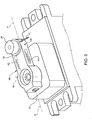
Figure 3 shows a perspective view of a portion of the intracortical-detection system illustrated inFigure 2 ; -
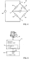
Figure 4 shows an electrical diagram of a Wheatstone-bridge circuit; -
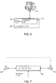
Figures 5 ,6 and 7 show block diagrams regarding portions of the intracortical-detection system illustrated inFigure 2 ; -
Figure 8 is a perspective view of a variant of a crank of the intracortical-detection system illustrated inFigure 2 ; and -
Figure 9 shows qualitatively a distribution of the mechanical stresses along the crank illustrated inFigure 8 . -
Figure 2 shows an intracortical-detection system comprising an intracortical-detection device, referred to hereinafter asdetection system 40 anddetection device 41, respectively. Thedetection system 40 and thedetection device 41 are described hereinafter, the present description being limited just to the differences with respect to the detection system 1 and to the detection device 2 described previously and illustrated inFigure 1 . Moreover, components of thedetection system 40 already present in the detection system 1 described previously are designated in the same way, except where otherwise specified. - In detail, the
detection device 41 comprises afirst strain gauge 42 and a second strain gauge 44 (illustrated inFigure 3 ), of a type in itself known. In particular, each of the first and second strain gauges 42, 44 is a transducer that is able to vary its own electrical resistance as a function of a mechanical deformation to which it is subjected. Even more in particular, each of the first and second strain gauges 42, 44 can be formed, in a way in itself known, by a wire made of semiconductor material. - As illustrated in greater detail in
Figure 3 , the first and second strain gauges 42, 44 are arranged, respectively, on afirst face 46 and asecond face 48 of thecrank 16 opposite to one another. In detail, the first and second faces 46, 48 are arranged parallel to the axis of rotation R and to the crank axis H, i.e., are parallel to the plane defined by this axis of rotation R and this crank axis H. - Even though they are not illustrated, the first and second strain gauges 42, 44 are electrically connected to the electronic card, here designated by 45. Moreover, the
electronic card 45 includes a firstresistive element 52 and a secondresistive element 54, which, as illustrated inFigure 4 , form, together with the first and second strain gauges 42, 44, a Wheatstone-bridgeelectrical circuit 55. - In detail, the first and second strain gauges 42, 44 are connected in a first reading node n1, whilst the first and second
resistive elements first strain gauge 42 and the firstresistive element 52 are connected in a first biasing node n3, whilst thesecond strain gauge 44 and the secondresistive element 54 are connected in a second biasing node n4. - In greater detail, according to a possible embodiment, the first and second strain gauges 42, 44 are the same as one another and have a value of resistance at rest, i.e., in the absence of tensile or compressive forces, equal to Rs. Moreover, the first and second
resistive elements - The
electronic card 45 moreover includes avoltage generator 58, which is connected between the first and second biasing nodes n3, n4 in such a way as to impose a biasing voltage between them. Moreover, theelectronic card 45 comprises avoltage detector 60, which is connected between the first and second reading nodes n1, n2 and is designed to determine a reading voltage, present between the first and second reading nodes n1, n2. In other words, thevoltage detector 60 is designed to supply an electrical read signal, indicating the voltage present between the first and second reading nodes n1, n2. - Operatively, the cerebral tissue exerts a pressure against the
surface 30 of thecontact element 14. Moreover, since the first andsecond bodies guide 22 and theslide 24, thefirst body 3 can move only in a direction parallel to the longitudinal axis L of thedetection device 41; consequently, the pressure exerted by the cerebral tissue on thesurface 30 is transmitted to thepin 26. As illustrated inFigure 3 , this means that thepin 26 is subject to a force Fp, which causes a deformation of thecrank 16, and hence of the first and second faces 46, 48. - The deformation of the first and second faces 46, 48 causes a variation of the resistances of the first and second strain gauges 42, 44. In fact, we find that the resistance of one between the first and second strain gauges 42, 44 increases with respect to the value at rest, whereas the resistance of the other decreases. In particular, we find that one between the first and second strain gauges 42, 44 assumes a resistance equal to Rs+Rp, whereas the other assumes a resistance equal to Rs-Rp.
- The reading voltage present between the first and second reading nodes n1, n2 is proportional to the resistance Rp, which depends linearly upon the force Fp. The electrical read signal supplied by the
voltage detector 60 hence indicates the pressure exerted by the cerebral tissue on thesurface 30 of thecontact element 14. - As illustrated in
Figure 5 , in a way in itself known, theelectronic card 45 can supply the electrical read signal to the peripheral electronic unit, which is here and inFigure 2 designated by 70. - In particular, the peripheral
electronic unit 70 includes aprocessing circuit 72, electrically connected to thevoltage detector 60 and designed to determine the pressure exerted by the cerebral tissue on thesurface 30 of thecontact element 14, on the basis of the electrical read signal supplied by thevoltage detector 60. In detail, theprocessing circuit 72 generates an electrical measurement signal, which represents the pressure exerted by the cerebral tissue on thesurface 30 of thecontact element 14. In other words, the Wheatstone-bridgeelectrical circuit 55, thevoltage detector 60, and theprocessing circuit 72 form an electrical pressure sensor. - The peripheral
electronic unit 70 can thus supply to the control station P, to which it is connected, the electrical measurement signal, as determined by theprocessing circuit 72. In a way in itself known, the control station P includes a screen and is programmed to enable display on this screen of the values of the pressure exerted instant by instant by the cerebral tissue on thesurface 30 of thecontact element 14, as represented by the electrical measurement signal. - Thanks to the
detection system 40, the surgeon can continuously have available quantitative information regarding the pressure exerted by the cerebral tissue on thesurface 30, and can hence govern with greater precision the secondelectric motor 10, in order to apply on the first portion of cerebral region an initial static pressure adequate to guarantee contact between thesurface 30 and the cerebral tissue, thus countering the bulging without inducing ischaemias. - Alternatively, as illustrated in
Figure 6 , theelectronic unit 45 can itself include theprocessing circuit 72, once again connected to thevoltage detector 60. In this case, theprocessing circuit 72 can be directly connected to the control station P. - In order to enable also compensation of pulsations of the cerebral tissue, it is moreover possible to adopt the embodiment illustrated in
Figure 7 . According to this embodiment, the electrical read signal supplied by thevoltage detector 60 is used for controlling in closed loop the secondelectric motor 10, so that the position of thedetection device 41, and in particular the position of thefirst body 3 with respect to thesecond body 4, adapts dynamically as a function of the instantaneous pressure exerted by the cerebral tissue on thesurface 30. - In detail, according to this embodiment, the
detection system 40 includes acontrol unit 80, which is of an electronic type and is electrically connected to thevoltage detector 60 and to the secondelectric motor 10. In particular, thecontrol unit 80 is arranged between thevoltage detector 60 and the secondelectric motor 10. Moreover, thecontrol unit 80 can be formed within theelectronic card 45 or else within the peripheralelectronic unit 70. - In greater detail, the
control unit 80 governs the secondelectric motor 10 as a function of the electrical read signal generated by thevoltage detector 60, i.e., as a function of the pressure exerted by the cerebral tissue on thesurface 30. - In particular, in a way in itself known, the
control unit 80 is designed to implement a control of the secondelectric motor 10 of the so-called "proportional-integral-derivative" (PID) type, on the basis of the electrical read signal supplied by thevoltage detector 60 and of an electrical reference signal, which can be set by the user. For example, the electrical reference signal can be such that, in the (hypothetical) absence of pulsations, the pressure exerted by thesurface 30 is equal to an optimal static pressure for the purposes of containment of bulging. - In other words, the
voltage detector 60, thecontrol unit 80, and the secondelectric motor 10 form a closed-loop control circuit of the secondelectric motor 10, since the electrical read signal supplied by thevoltage detector 60 depends upon the position of thefirst body 3 with respect to thesecond body 4 and is hence affected by the operation of the secondelectric motor 10. Consequently, the secondelectric motor 10 is governed on the basis of a quantity (the reading voltage) that depends upon operation of theelectric motor 10. - Operatively, the closed-loop control circuit causes the second
electric motor 10 to be governed in such a way as to keep the pressure exerted by thesurface 30 on the cerebral tissue constant. Equivalently, the secondelectric motor 10 is governed so that the relative position of the array ofelectrodes 6 with respect to the cerebral tissue does not vary on account of pulsation of the cerebral tissue. In other words, the array ofelectrodes 6 moves, under the action of the secondelectric motor 10, together with thefirst body 3, in such a way as to follow the movements of the cerebral tissue due to pulsation. In this way, not only is the position of the electrodes within the cerebral tissue kept constant, but moreover rubbing of the electrodes against the cerebral tissue in which they are inserted is limited, with consequent reduction of the electrical noise caused by this rubbing. - In order to increase the sensitivity of the first and second strain gauges 42, 44 with respect to the pressure exerted by the cerebral tissue on the
surface 30, i.e., in order to increase the variation of resistance (Rp) of the first and second strain gauges 42, 44 given the same force Fp, it is moreover possible to adopt a crank of the type illustrated inFigure 8 , where it is designated by 90. - In detail, the
crank 90 is elongated along the crank axis H and is S-shaped. Moreover, thecrank 90 includes a firstperipheral portion 92 and a secondperipheral portion 94, which are arranged on the crank axis H and function respectively as first and second ends of thecrank 90; the first and secondperipheral portions electric motor 10 and to thepin 26, the latter being also here fixed with respect to thecrank 90. - In greater detail, the first and second
peripheral portions curved portion 96 and secondcurved portion 98, as well as by aplane portion 100, the latter being arranged between, and connected to, the first and secondcurved portions curved portions plane portion 100 but also to the first and secondperipheral portions - The first and second
peripheral portions curved portions plane portion 100 defines afirst face 102 and asecond face 104, both plane and parallel to one another, and on which the first and second strain gauges 42, 44 are respectively arranged. In particular, the first andsecond faces crank 90 turns. - Given the same force Fp, the S-shaped
crank 90 deforms more than thecrank 16. Furthermore, the first andsecond faces Figure 9 shows qualitatively the distribution of the mechanical stresses along thecrank 90. Consequently, given the same force Fp, the first and second strain gauges 42, 44 undergo a deformation greater than the case where they are constrained on thefirst face 46 and on thesecond face 48 of thecrank 16. Consequently, the sensitivity of the electrical pressure sensor formed by the Wheatstone-bridgeelectrical circuit 55, by thevoltage detector 60, and by theprocessing circuit 72 is increased. - The advantages that the present detection device affords emerge clearly from the foregoing description.
- In particular, the present detection device makes it possible to provide the surgeon in real time with quantitative information on the pressure effectively exerted by the cerebral tissue on the
surface 30 of thecontact element 14, enabling him to regulate correctly the pressure exerted by the detection device 2 on the cerebral tissue. - In addition, according to the embodiment illustrated in
Figure 7 , the instantaneous pressure exerted by thesurface 30 on the cerebral tissue is kept substantially constant, irrespective of the pulsations of the cerebral tissue, which are precisely compensated dynamically in an automatic way thanks to the closed-loop control of the secondelectric motor 10. This compensation is made independently of the positioning of the array ofelectrodes 6 and moreover enables limitation of the electrical noise due to the relative motion of the array ofelectrodes 6 with respect to the cerebral tissue in which it is immersed. - Finally, it is evident that modifications and variations may be made to the present detection device, without thereby departing from the scope of the present invention.
- For instance, instead of the first and second strain gauges 42, 44, transducers of a different type may be used, such as for example piezo-capacitive or piezo-resistive pressure sensors set on the
surface 30. In addition, the arrangements of the first and second strain gauges 42, 44 may be different from what has been illustrated. - Likewise, variations may be made to the Wheatstone-bridge
electrical circuit 55. For example, in a way in itself known, theelectronic card 45 can control the voltage present on the second reading node n2 in order to prevent saturation of the Wheatstone-bridgeelectrical circuit 55 due to the inevitable differences between the resistances of the first and second strain gauges 42, 44 and of the first and secondresistive elements electronic card 45 can include a digital-to-analog converter (not illustrated) designed to impose, in a way in itself known, the voltage on the second reading node n2. - It is likewise possible for the first and second strain gauges 42, 44 to form a circuit of a type different from the Wheatstone-bridge
electrical circuit 55.
Claims (9)
- An intracortical-detection device comprising:- at least one electrode (6) designed to contact a group of neurons;- a first body (3), forming a surface (30) designed to contact a portion of a cerebral region;- a first motor (8) configured to move said at least one electrode with respect to said first body; and- a second motor (10), which is fixed with respect to the first body; and- a second body (4), operatively connected to said second motor, said first and second bodies being able to slide with respect to one another in a first direction (x), under the action of said second motor;- a crank (16; 90), which is coupled to said second body and can be driven in rotation by said second motor about a second direction (R) transverse with respect to said first direction (x); and- constraint means (22, 24) designed to prevent the motion of said first body with respect to said second body in directions different from said first direction; characterized by further comprisingsensor means (42,44,55) configured to generate an electrical signal indicating a pressure exerted by said portion of cerebral region on said surface;
wherein said sensor means comprise transducer means (42, 44) arranged on said crank and configured to vary an own electrical quantity as a function of a deformation of said crank caused by the pressure exerted by said portion of cerebral region on said surface. - The detection device according to claim 1, further comprising a control unit (80) configured to govern said second motor (10) as a function of said electrical signal.
- The detection device according to claim 2, wherein said control unit (80) is configured to control said second motor (10) so that said surface (30) exerts a substantially constant pressure on said portion of cerebral region.
- The detection device according to claim 3, wherein said control unit (80) is configured to control said second motor (10) according to a control of the PID (proportional-integral-derivative) type.
- The detection device according to any of the preceding claims, wherein said crank (90) is S-shaped and defines a first face (102) and a second face (104) parallel to one another and parallel to said second direction (R), said transducer means (42, 44) being arranged on said first and second faces.
- The detection device according to claim 5, further comprising a groove (20) fixed with respect to said second body (4) and directed in a third direction (z) transverse with respect to said first and second directions (x, R), and a pin (26), fixed with respect to said crank (16; 90) and cooperating with said groove; and wherein said crank includes a first end (92) and a second end (94) arranged in an axial direction (H) and constrained to said second electric motor (10) and to said pin, respectively, and an intermediate portion (100) arranged between said first and second ends; and wherein said first and second faces (102, 104) are formed by said intermediate portion and are transverse with respect to said axial direction (H).
- The detection device according to claim 5 or claim 6, wherein said transducer means comprise a first strain gauge (42) and a second strain gauge (44), arranged on said first and second faces (102, 104), respectively.
- The detection device according to any one of the preceding claims, wherein said constraint means comprise a guide (22), fixed with respect to said first body (3) and parallel to said first direction (x), and a slide (24), fixed with respect to said second body (4) and constrained to move along said guide.
- An intracortical-detection system comprising an intracortical-detection device (2) according to any one of the preceding claims and a display device (P), electrically connected to said sensor means (42, 44, 55).
Applications Claiming Priority (2)
| Application Number | Priority Date | Filing Date | Title |
|---|---|---|---|
| IT000516A ITTO20110516A1 (en) | 2011-06-10 | 2011-06-10 | INTRACORTIC DETECTION DEVICE AND ITS CONTROL METHOD |
| PCT/IB2012/052948 WO2012168928A1 (en) | 2011-06-10 | 2012-06-11 | Intracortical-detection device and corresponding control method |
Publications (2)
| Publication Number | Publication Date |
|---|---|
| EP2717764A1 EP2717764A1 (en) | 2014-04-16 |
| EP2717764B1 true EP2717764B1 (en) | 2019-10-16 |
Family
ID=44514902
Family Applications (1)
| Application Number | Title | Priority Date | Filing Date |
|---|---|---|---|
| EP12745527.7A Active EP2717764B1 (en) | 2011-06-10 | 2012-06-11 | Intracortical-detection device and corresponding control method |
Country Status (4)
| Country | Link |
|---|---|
| US (1) | US9848792B2 (en) |
| EP (1) | EP2717764B1 (en) |
| IT (1) | ITTO20110516A1 (en) |
| WO (1) | WO2012168928A1 (en) |
Families Citing this family (7)
| Publication number | Priority date | Publication date | Assignee | Title |
|---|---|---|---|---|
| WO2019060298A1 (en) | 2017-09-19 | 2019-03-28 | Neuroenhancement Lab, LLC | Method and apparatus for neuroenhancement |
| US11717686B2 (en) | 2017-12-04 | 2023-08-08 | Neuroenhancement Lab, LLC | Method and apparatus for neuroenhancement to facilitate learning and performance |
| US12280219B2 (en) | 2017-12-31 | 2025-04-22 | NeuroLight, Inc. | Method and apparatus for neuroenhancement to enhance emotional response |
| US11318277B2 (en) | 2017-12-31 | 2022-05-03 | Neuroenhancement Lab, LLC | Method and apparatus for neuroenhancement to enhance emotional response |
| US11364361B2 (en) | 2018-04-20 | 2022-06-21 | Neuroenhancement Lab, LLC | System and method for inducing sleep by transplanting mental states |
| CN113382683A (en) | 2018-09-14 | 2021-09-10 | 纽罗因恒思蒙特实验有限责任公司 | System and method for improving sleep |
| US11786694B2 (en) | 2019-05-24 | 2023-10-17 | NeuroLight, Inc. | Device, method, and app for facilitating sleep |
Family Cites Families (7)
| Publication number | Priority date | Publication date | Assignee | Title |
|---|---|---|---|---|
| US3841310A (en) * | 1973-04-04 | 1974-10-15 | Us Health Education & Welfare | Electrode insertion device for neuroelectrical recordings |
| CA2083686C (en) * | 1991-11-27 | 2001-08-21 | Ross G. Stone | Tension headache reliever |
| US5396415A (en) * | 1992-01-31 | 1995-03-07 | Honeywell Inc. | Neruo-pid controller |
| JP2001231759A (en) * | 2000-02-24 | 2001-08-28 | Tomy Ltd | Brain electrode fixation device |
| US7660621B2 (en) * | 2000-04-07 | 2010-02-09 | Medtronic, Inc. | Medical device introducer |
| US7277742B2 (en) * | 2005-05-19 | 2007-10-02 | Ad-Tech Medical Instrument Corporation | Cortical electrode support assembly |
| US20070156126A1 (en) * | 2005-12-29 | 2007-07-05 | Flaherty J C | Medical device insertion system and related methods |
-
2011
- 2011-06-10 IT IT000516A patent/ITTO20110516A1/en unknown
-
2012
- 2012-06-11 EP EP12745527.7A patent/EP2717764B1/en active Active
- 2012-06-11 WO PCT/IB2012/052948 patent/WO2012168928A1/en not_active Ceased
- 2012-06-11 US US14/125,058 patent/US9848792B2/en not_active Expired - Fee Related
Non-Patent Citations (1)
| Title |
|---|
| None * |
Also Published As
| Publication number | Publication date |
|---|---|
| ITTO20110516A1 (en) | 2012-12-11 |
| EP2717764A1 (en) | 2014-04-16 |
| WO2012168928A1 (en) | 2012-12-13 |
| US9848792B2 (en) | 2017-12-26 |
| US20140336489A1 (en) | 2014-11-13 |
Similar Documents
| Publication | Publication Date | Title |
|---|---|---|
| US9848792B2 (en) | Intracortical-detection device and corresponding control method | |
| US8996094B2 (en) | Method and system for compensating a self-caused displacement of tissue | |
| JP7033614B6 (en) | Measurement of electrical activity | |
| Tidswell et al. | Three-dimensional electrical impedance tomography of human brain activity | |
| Fiedler et al. | Novel multipin electrode cap system for dry electroencephalography | |
| CN107072528B (en) | System and method for monitoring eye health | |
| US20160030762A1 (en) | Device and method for transcranial magnetic stimulation coil positioning with data integration | |
| US20070156126A1 (en) | Medical device insertion system and related methods | |
| US20100023021A1 (en) | Biological Interface and Insertion | |
| KR101768393B1 (en) | Individual brain function measuring apparatus abnormality part using EEG | |
| WO2008067839A1 (en) | Dry electrode cap for electro-encephalography | |
| EP3092617A1 (en) | A system and a method for transcranial stimulation of a head region of a subject | |
| Orsborn et al. | Semi-chronic chamber system for simultaneous subdural electrocorticography, local field potentials, and spike recordings | |
| Hageman et al. | Low-noise magnetic coil system for recording 3-D eye movements | |
| DE102017117053B4 (en) | FACE PAD | |
| US20100106165A1 (en) | Retention device, medical robot and method to set the tool center point of a medical robot | |
| Bevilacqua et al. | A Wearable Wireless Magnetic Eye-Tracker, in-vitro and in-vivo tests | |
| Jetzki et al. | A multisensor implant for continuous monitoring of intracranial pressure dynamics | |
| RU2372023C1 (en) | Device for measuring intracranial pressure in newborn babies and infants and supporting element for said device | |
| Kanayama et al. | Controlled emotional tactile stimulation during functional magnetic resonance imaging and electroencephalography | |
| US20240315665A1 (en) | Method and system for observing brain states with functional ultrasound imaging and a sonolucent interface | |
| Seipel | The biophysical basis and clinical applications of rheoencephalography. | |
| Hess et al. | Vestibular contributions to gaze stability during transient forward and backward motion | |
| KR101780264B1 (en) | Apparatus for measuring photoplethysmograph and method of measuring photoplethysmo graph | |
| KR20240014688A (en) | EEG measuring apparatus |
Legal Events
| Date | Code | Title | Description |
|---|---|---|---|
| PUAI | Public reference made under article 153(3) epc to a published international application that has entered the european phase |
Free format text: ORIGINAL CODE: 0009012 |
|
| 17P | Request for examination filed |
Effective date: 20131212 |
|
| AK | Designated contracting states |
Kind code of ref document: A1 Designated state(s): AL AT BE BG CH CY CZ DE DK EE ES FI FR GB GR HR HU IE IS IT LI LT LU LV MC MK MT NL NO PL PT RO RS SE SI SK SM TR |
|
| DAX | Request for extension of the european patent (deleted) | ||
| STAA | Information on the status of an ep patent application or granted ep patent |
Free format text: STATUS: EXAMINATION IS IN PROGRESS |
|
| 17Q | First examination report despatched |
Effective date: 20180905 |
|
| GRAP | Despatch of communication of intention to grant a patent |
Free format text: ORIGINAL CODE: EPIDOSNIGR1 |
|
| STAA | Information on the status of an ep patent application or granted ep patent |
Free format text: STATUS: GRANT OF PATENT IS INTENDED |
|
| INTG | Intention to grant announced |
Effective date: 20190510 |
|
| RIN1 | Information on inventor provided before grant (corrected) |
Inventor name: ANGOTZI, GIAN NICOLA Inventor name: SANDINI, GIULIO Inventor name: FADIGA, LUCIANO |
|
| GRAS | Grant fee paid |
Free format text: ORIGINAL CODE: EPIDOSNIGR3 |
|
| GRAA | (expected) grant |
Free format text: ORIGINAL CODE: 0009210 |
|
| STAA | Information on the status of an ep patent application or granted ep patent |
Free format text: STATUS: THE PATENT HAS BEEN GRANTED |
|
| AK | Designated contracting states |
Kind code of ref document: B1 Designated state(s): AL AT BE BG CH CY CZ DE DK EE ES FI FR GB GR HR HU IE IS IT LI LT LU LV MC MK MT NL NO PL PT RO RS SE SI SK SM TR |
|
| REG | Reference to a national code |
Ref country code: GB Ref legal event code: FG4D |
|
| REG | Reference to a national code |
Ref country code: CH Ref legal event code: EP |
|
| REG | Reference to a national code |
Ref country code: DE Ref legal event code: R096 Ref document number: 602012064906 Country of ref document: DE |
|
| REG | Reference to a national code |
Ref country code: IE Ref legal event code: FG4D |
|
| REG | Reference to a national code |
Ref country code: AT Ref legal event code: REF Ref document number: 1190493 Country of ref document: AT Kind code of ref document: T Effective date: 20191115 |
|
| REG | Reference to a national code |
Ref country code: NL Ref legal event code: MP Effective date: 20191016 |
|
| REG | Reference to a national code |
Ref country code: LT Ref legal event code: MG4D |
|
| REG | Reference to a national code |
Ref country code: AT Ref legal event code: MK05 Ref document number: 1190493 Country of ref document: AT Kind code of ref document: T Effective date: 20191016 |
|
| PG25 | Lapsed in a contracting state [announced via postgrant information from national office to epo] |
Ref country code: PT Free format text: LAPSE BECAUSE OF FAILURE TO SUBMIT A TRANSLATION OF THE DESCRIPTION OR TO PAY THE FEE WITHIN THE PRESCRIBED TIME-LIMIT Effective date: 20200217 Ref country code: NO Free format text: LAPSE BECAUSE OF FAILURE TO SUBMIT A TRANSLATION OF THE DESCRIPTION OR TO PAY THE FEE WITHIN THE PRESCRIBED TIME-LIMIT Effective date: 20200116 Ref country code: LT Free format text: LAPSE BECAUSE OF FAILURE TO SUBMIT A TRANSLATION OF THE DESCRIPTION OR TO PAY THE FEE WITHIN THE PRESCRIBED TIME-LIMIT Effective date: 20191016 Ref country code: PL Free format text: LAPSE BECAUSE OF FAILURE TO SUBMIT A TRANSLATION OF THE DESCRIPTION OR TO PAY THE FEE WITHIN THE PRESCRIBED TIME-LIMIT Effective date: 20191016 Ref country code: GR Free format text: LAPSE BECAUSE OF FAILURE TO SUBMIT A TRANSLATION OF THE DESCRIPTION OR TO PAY THE FEE WITHIN THE PRESCRIBED TIME-LIMIT Effective date: 20200117 Ref country code: NL Free format text: LAPSE BECAUSE OF FAILURE TO SUBMIT A TRANSLATION OF THE DESCRIPTION OR TO PAY THE FEE WITHIN THE PRESCRIBED TIME-LIMIT Effective date: 20191016 Ref country code: ES Free format text: LAPSE BECAUSE OF FAILURE TO SUBMIT A TRANSLATION OF THE DESCRIPTION OR TO PAY THE FEE WITHIN THE PRESCRIBED TIME-LIMIT Effective date: 20191016 Ref country code: LV Free format text: LAPSE BECAUSE OF FAILURE TO SUBMIT A TRANSLATION OF THE DESCRIPTION OR TO PAY THE FEE WITHIN THE PRESCRIBED TIME-LIMIT Effective date: 20191016 Ref country code: SE Free format text: LAPSE BECAUSE OF FAILURE TO SUBMIT A TRANSLATION OF THE DESCRIPTION OR TO PAY THE FEE WITHIN THE PRESCRIBED TIME-LIMIT Effective date: 20191016 Ref country code: AT Free format text: LAPSE BECAUSE OF FAILURE TO SUBMIT A TRANSLATION OF THE DESCRIPTION OR TO PAY THE FEE WITHIN THE PRESCRIBED TIME-LIMIT Effective date: 20191016 Ref country code: FI Free format text: LAPSE BECAUSE OF FAILURE TO SUBMIT A TRANSLATION OF THE DESCRIPTION OR TO PAY THE FEE WITHIN THE PRESCRIBED TIME-LIMIT Effective date: 20191016 Ref country code: BG Free format text: LAPSE BECAUSE OF FAILURE TO SUBMIT A TRANSLATION OF THE DESCRIPTION OR TO PAY THE FEE WITHIN THE PRESCRIBED TIME-LIMIT Effective date: 20200116 |
|
| PG25 | Lapsed in a contracting state [announced via postgrant information from national office to epo] |
Ref country code: IS Free format text: LAPSE BECAUSE OF FAILURE TO SUBMIT A TRANSLATION OF THE DESCRIPTION OR TO PAY THE FEE WITHIN THE PRESCRIBED TIME-LIMIT Effective date: 20200224 Ref country code: RS Free format text: LAPSE BECAUSE OF FAILURE TO SUBMIT A TRANSLATION OF THE DESCRIPTION OR TO PAY THE FEE WITHIN THE PRESCRIBED TIME-LIMIT Effective date: 20191016 Ref country code: HR Free format text: LAPSE BECAUSE OF FAILURE TO SUBMIT A TRANSLATION OF THE DESCRIPTION OR TO PAY THE FEE WITHIN THE PRESCRIBED TIME-LIMIT Effective date: 20191016 |
|
| PG25 | Lapsed in a contracting state [announced via postgrant information from national office to epo] |
Ref country code: AL Free format text: LAPSE BECAUSE OF FAILURE TO SUBMIT A TRANSLATION OF THE DESCRIPTION OR TO PAY THE FEE WITHIN THE PRESCRIBED TIME-LIMIT Effective date: 20191016 |
|
| REG | Reference to a national code |
Ref country code: DE Ref legal event code: R097 Ref document number: 602012064906 Country of ref document: DE |
|
| PG2D | Information on lapse in contracting state deleted |
Ref country code: IS |
|
| PG25 | Lapsed in a contracting state [announced via postgrant information from national office to epo] |
Ref country code: DK Free format text: LAPSE BECAUSE OF FAILURE TO SUBMIT A TRANSLATION OF THE DESCRIPTION OR TO PAY THE FEE WITHIN THE PRESCRIBED TIME-LIMIT Effective date: 20191016 Ref country code: RO Free format text: LAPSE BECAUSE OF FAILURE TO SUBMIT A TRANSLATION OF THE DESCRIPTION OR TO PAY THE FEE WITHIN THE PRESCRIBED TIME-LIMIT Effective date: 20191016 Ref country code: CZ Free format text: LAPSE BECAUSE OF FAILURE TO SUBMIT A TRANSLATION OF THE DESCRIPTION OR TO PAY THE FEE WITHIN THE PRESCRIBED TIME-LIMIT Effective date: 20191016 Ref country code: EE Free format text: LAPSE BECAUSE OF FAILURE TO SUBMIT A TRANSLATION OF THE DESCRIPTION OR TO PAY THE FEE WITHIN THE PRESCRIBED TIME-LIMIT Effective date: 20191016 Ref country code: IS Free format text: LAPSE BECAUSE OF FAILURE TO SUBMIT A TRANSLATION OF THE DESCRIPTION OR TO PAY THE FEE WITHIN THE PRESCRIBED TIME-LIMIT Effective date: 20200216 |
|
| PLBE | No opposition filed within time limit |
Free format text: ORIGINAL CODE: 0009261 |
|
| STAA | Information on the status of an ep patent application or granted ep patent |
Free format text: STATUS: NO OPPOSITION FILED WITHIN TIME LIMIT |
|
| PG25 | Lapsed in a contracting state [announced via postgrant information from national office to epo] |
Ref country code: SK Free format text: LAPSE BECAUSE OF FAILURE TO SUBMIT A TRANSLATION OF THE DESCRIPTION OR TO PAY THE FEE WITHIN THE PRESCRIBED TIME-LIMIT Effective date: 20191016 Ref country code: SM Free format text: LAPSE BECAUSE OF FAILURE TO SUBMIT A TRANSLATION OF THE DESCRIPTION OR TO PAY THE FEE WITHIN THE PRESCRIBED TIME-LIMIT Effective date: 20191016 |
|
| 26N | No opposition filed |
Effective date: 20200717 |
|
| REG | Reference to a national code |
Ref country code: DE Ref legal event code: R079 Ref document number: 602012064906 Country of ref document: DE Free format text: PREVIOUS MAIN CLASS: A61B0005040000 Ipc: A61B0005240000 |
|
| PG25 | Lapsed in a contracting state [announced via postgrant information from national office to epo] |
Ref country code: SI Free format text: LAPSE BECAUSE OF FAILURE TO SUBMIT A TRANSLATION OF THE DESCRIPTION OR TO PAY THE FEE WITHIN THE PRESCRIBED TIME-LIMIT Effective date: 20191016 |
|
| PG25 | Lapsed in a contracting state [announced via postgrant information from national office to epo] |
Ref country code: MC Free format text: LAPSE BECAUSE OF FAILURE TO SUBMIT A TRANSLATION OF THE DESCRIPTION OR TO PAY THE FEE WITHIN THE PRESCRIBED TIME-LIMIT Effective date: 20191016 |
|
| REG | Reference to a national code |
Ref country code: CH Ref legal event code: PL |
|
| PG25 | Lapsed in a contracting state [announced via postgrant information from national office to epo] |
Ref country code: LU Free format text: LAPSE BECAUSE OF NON-PAYMENT OF DUE FEES Effective date: 20200611 |
|
| REG | Reference to a national code |
Ref country code: BE Ref legal event code: MM Effective date: 20200630 |
|
| PG25 | Lapsed in a contracting state [announced via postgrant information from national office to epo] |
Ref country code: LI Free format text: LAPSE BECAUSE OF NON-PAYMENT OF DUE FEES Effective date: 20200630 Ref country code: IE Free format text: LAPSE BECAUSE OF NON-PAYMENT OF DUE FEES Effective date: 20200611 Ref country code: CH Free format text: LAPSE BECAUSE OF NON-PAYMENT OF DUE FEES Effective date: 20200630 |
|
| PG25 | Lapsed in a contracting state [announced via postgrant information from national office to epo] |
Ref country code: BE Free format text: LAPSE BECAUSE OF NON-PAYMENT OF DUE FEES Effective date: 20200630 |
|
| PG25 | Lapsed in a contracting state [announced via postgrant information from national office to epo] |
Ref country code: TR Free format text: LAPSE BECAUSE OF FAILURE TO SUBMIT A TRANSLATION OF THE DESCRIPTION OR TO PAY THE FEE WITHIN THE PRESCRIBED TIME-LIMIT Effective date: 20191016 Ref country code: MT Free format text: LAPSE BECAUSE OF FAILURE TO SUBMIT A TRANSLATION OF THE DESCRIPTION OR TO PAY THE FEE WITHIN THE PRESCRIBED TIME-LIMIT Effective date: 20191016 Ref country code: CY Free format text: LAPSE BECAUSE OF FAILURE TO SUBMIT A TRANSLATION OF THE DESCRIPTION OR TO PAY THE FEE WITHIN THE PRESCRIBED TIME-LIMIT Effective date: 20191016 |
|
| PG25 | Lapsed in a contracting state [announced via postgrant information from national office to epo] |
Ref country code: MK Free format text: LAPSE BECAUSE OF FAILURE TO SUBMIT A TRANSLATION OF THE DESCRIPTION OR TO PAY THE FEE WITHIN THE PRESCRIBED TIME-LIMIT Effective date: 20191016 |
|
| P01 | Opt-out of the competence of the unified patent court (upc) registered |
Effective date: 20230414 |
|
| PGFP | Annual fee paid to national office [announced via postgrant information from national office to epo] |
Ref country code: FR Payment date: 20230622 Year of fee payment: 12 Ref country code: DE Payment date: 20230627 Year of fee payment: 12 |
|
| PGFP | Annual fee paid to national office [announced via postgrant information from national office to epo] |
Ref country code: GB Payment date: 20230620 Year of fee payment: 12 |
|
| PGFP | Annual fee paid to national office [announced via postgrant information from national office to epo] |
Ref country code: IT Payment date: 20240604 Year of fee payment: 13 |
|
| REG | Reference to a national code |
Ref country code: DE Ref legal event code: R119 Ref document number: 602012064906 Country of ref document: DE |
|
| GBPC | Gb: european patent ceased through non-payment of renewal fee |
Effective date: 20240611 |
|
| PG25 | Lapsed in a contracting state [announced via postgrant information from national office to epo] |
Ref country code: DE Free format text: LAPSE BECAUSE OF NON-PAYMENT OF DUE FEES Effective date: 20250101 |
|
| PG25 | Lapsed in a contracting state [announced via postgrant information from national office to epo] |
Ref country code: FR Free format text: LAPSE BECAUSE OF NON-PAYMENT OF DUE FEES Effective date: 20240630 |
|
| PG25 | Lapsed in a contracting state [announced via postgrant information from national office to epo] |
Ref country code: GB Free format text: LAPSE BECAUSE OF NON-PAYMENT OF DUE FEES Effective date: 20240611 |
|
| PG25 | Lapsed in a contracting state [announced via postgrant information from national office to epo] |
Ref country code: IT Free format text: LAPSE BECAUSE OF NON-PAYMENT OF DUE FEES Effective date: 20250611 |