EP2717550A1 - Portable apparatus with a receiver and two sound holes - Google Patents
Portable apparatus with a receiver and two sound holes Download PDFInfo
- Publication number
- EP2717550A1 EP2717550A1 EP13161106.3A EP13161106A EP2717550A1 EP 2717550 A1 EP2717550 A1 EP 2717550A1 EP 13161106 A EP13161106 A EP 13161106A EP 2717550 A1 EP2717550 A1 EP 2717550A1
- Authority
- EP
- European Patent Office
- Prior art keywords
- sound hole
- sound
- main body
- portable apparatus
- passive
- Prior art date
- Legal status (The legal status is an assumption and is not a legal conclusion. Google has not performed a legal analysis and makes no representation as to the accuracy of the status listed.)
- Withdrawn
Links
Images



Classifications
-
- H—ELECTRICITY
- H04—ELECTRIC COMMUNICATION TECHNIQUE
- H04R—LOUDSPEAKERS, MICROPHONES, GRAMOPHONE PICK-UPS OR LIKE ACOUSTIC ELECTROMECHANICAL TRANSDUCERS; ELECTRIC HEARING AIDS; PUBLIC ADDRESS SYSTEMS
- H04R1/00—Details of transducers, loudspeakers or microphones
- H04R1/20—Arrangements for obtaining desired frequency or directional characteristics
- H04R1/22—Arrangements for obtaining desired frequency or directional characteristics for obtaining desired frequency characteristic only
- H04R1/28—Transducer mountings or enclosures modified by provision of mechanical or acoustic impedances, e.g. resonator, damping means
-
- H—ELECTRICITY
- H04—ELECTRIC COMMUNICATION TECHNIQUE
- H04M—TELEPHONIC COMMUNICATION
- H04M1/00—Substation equipment, e.g. for use by subscribers
- H04M1/02—Constructional features of telephone sets
- H04M1/03—Constructional features of telephone transmitters or receivers, e.g. telephone hand-sets
- H04M1/035—Improving the acoustic characteristics by means of constructional features of the housing, e.g. ribs, walls, resonating chambers or cavities
-
- H—ELECTRICITY
- H04—ELECTRIC COMMUNICATION TECHNIQUE
- H04R—LOUDSPEAKERS, MICROPHONES, GRAMOPHONE PICK-UPS OR LIKE ACOUSTIC ELECTROMECHANICAL TRANSDUCERS; ELECTRIC HEARING AIDS; PUBLIC ADDRESS SYSTEMS
- H04R1/00—Details of transducers, loudspeakers or microphones
- H04R1/20—Arrangements for obtaining desired frequency or directional characteristics
- H04R1/32—Arrangements for obtaining desired frequency or directional characteristics for obtaining desired directional characteristic only
- H04R1/34—Arrangements for obtaining desired frequency or directional characteristics for obtaining desired directional characteristic only by using a single transducer with sound reflecting, diffracting, directing or guiding means
- H04R1/345—Arrangements for obtaining desired frequency or directional characteristics for obtaining desired directional characteristic only by using a single transducer with sound reflecting, diffracting, directing or guiding means for loudspeakers
-
- H—ELECTRICITY
- H04—ELECTRIC COMMUNICATION TECHNIQUE
- H04R—LOUDSPEAKERS, MICROPHONES, GRAMOPHONE PICK-UPS OR LIKE ACOUSTIC ELECTROMECHANICAL TRANSDUCERS; ELECTRIC HEARING AIDS; PUBLIC ADDRESS SYSTEMS
- H04R1/00—Details of transducers, loudspeakers or microphones
- H04R1/20—Arrangements for obtaining desired frequency or directional characteristics
- H04R1/22—Arrangements for obtaining desired frequency or directional characteristics for obtaining desired frequency characteristic only
- H04R1/28—Transducer mountings or enclosures modified by provision of mechanical or acoustic impedances, e.g. resonator, damping means
- H04R1/2807—Enclosures comprising vibrating or resonating arrangements
- H04R1/2811—Enclosures comprising vibrating or resonating arrangements for loudspeaker transducers
-
- H—ELECTRICITY
- H04—ELECTRIC COMMUNICATION TECHNIQUE
- H04R—LOUDSPEAKERS, MICROPHONES, GRAMOPHONE PICK-UPS OR LIKE ACOUSTIC ELECTROMECHANICAL TRANSDUCERS; ELECTRIC HEARING AIDS; PUBLIC ADDRESS SYSTEMS
- H04R2499/00—Aspects covered by H04R or H04S not otherwise provided for in their subgroups
- H04R2499/10—General applications
- H04R2499/11—Transducers incorporated or for use in hand-held devices, e.g. mobile phones, PDA's, camera's
Definitions
- the disclosure generally relates to a portable apparatus, and more particularly, to a portable apparatus with good receiving effect.
- a mobile device such as a handheld portable wireless telephone, adopts a receiver to concert electrical signals into sound waves with a human audible frequency range.
- the receiver is often disposed at a relatively upper position of the portable apparatus to be close to the ear of user, so that the user can receive the converted sound wave with the human audible frequency range.
- the current receiver has only one sound outgoing hole, so the sound waves are transmitted out of the portable apparatus in a single sound source mode. Therefore, while the user is listening to the voice with the receiver, if the positions of the receiver and the ear are not aligned with the single sound source, the user has a lower acoustic sensitivity on the sound wave and easily gets unclear voice, even no voice is heard.
- the disclosure is directed to a portable apparatus, in which during the user is listening to the voice with the portable apparatus, an active sound hole and a passive sound hole disposed at the portable apparatus respectively emit out sound waves, so that the sound source spots received by the ear with the human audible sound-pressure range are increased and the receiving effect is advanced.
- the disclosure provides a portable apparatus, which includes a main body and a receiver.
- the main body has a surface, an active sound hole and a passive sound hole.
- the active sound hole and the passive sound hole are both disposed at the surface of the main body.
- the receiver is disposed inside the main body and arranged for emitting a first sound wave and a second sound wave with the same amplitude and frequency but opposite transmission directions.
- the first sound wave is transmitted out of the main body via the active sound hole and the second sound wave is guided in the main body and transmitted out of the main body via the passive sound hole.
- the active sound hole and the passive sound hole are both disposed on the same surface of the main body. Therefore, while the user is listening voice with the portable apparatus, the user can receive different sound waves emitted from the active sound hole and the passive sound hole located at different positions, which increases the sweet spots of human audible sound-pressure and advances the receiving effect.
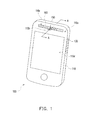
- Fig. 1 is a schematic diagram of a portable apparatus according to the first embodiment of the disclosure.
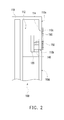
- Fig. 2 is a cross-sectional diagram of Fig. 1 along line A-A.
- Fig. 3 is a diagram showing the transmissions of the first sound wave and the second sound wave when the ear of a user is close to the portable apparatus.
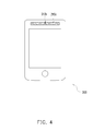
- Fig. 4 is a schematic diagram of a portable apparatus according to the second embodiment of the disclosure.
- Fig. 5 is a schematic diagram of a portable apparatus according to the third embodiment of the disclosure.
- Fig. 6 is a cross-sectional diagram of Fig. 5 along line B-B.
- the disclosure provides a portable apparatus which has better receiving effect in comparison with the conventional portable apparatus.
- directional terminology such as “front,” “back,” “left,” “right,” “top,” “bottom,” etc., is used with reference to the orientation of the figures being described. It should be noted the given embodiments and the relative positions between the components in the following are used for purposes of illustration and should not be regarded as limiting the disclosure.
- Fig. 1 is a schematic diagram of a portable apparatus 100 according to the first embodiment of the disclosure and Fig. 2 is a cross-sectional diagram of Fig. 1 along line A-A.
- the portable apparatus 100 includes a main body 110 and a receiver 120, in which the main body 110 has a surface 110a, an active sound hole 110b and a passive sound hole 110c.
- the active sound hole 110b and the passive sound hole 110c are both disposed at the surface 110a of the main body 110.
- the receiver 120 is disposed inside the main body 110 and arranged for emitting a first sound wave W1 and a second sound wave W2 with the same amplitude and frequency but opposite transmission directions (as shown by Fig. 3 ).
- the first sound wave W1 is transmitted out of the main body 110 via the active sound hole 110b and the second sound wave W2 is guided in the main body 110 and then transmitted out of the main body 110 via the passive sound hole 110c.
- the active sound hole 110b and a part of the passive sound hole 110c are overlapped with each other, but the active sound hole 110b and the passive sound hole 110c are isolated. In other words, the active sound hole 110b and the passive sound hole 110c are not entirely overlapped with each other.
- the effective radiating area of the active sound hole 110b is smaller and the effective radiating area of the active sound hole 110b ranges between 1 mm 2 and 4 mm 2 ; the effective radiating area of the passive sound hole 110c is larger than the active sound hole 110b and the effective radiating area of the passive sound hole 110c ranges between 10 mm 2 and 20 mm 2 .
- the ratio of the effective radiating area of the active sound hole 110b over the effective radiating area of the passive sound hole 110c is less than or equal to 1:3.
- the shapes of the active sound hole 110b and the passive sound hole 110c are not limited, which can be rectangle, square, circle, ellipse or a combination thereof depending on the industry design requirement.
- the main body 110 further has a sound-guiding chamber 112 surrounding at least one side of the receiver 120 and connected with the passive sound hole 110c.
- the sound-guiding chamber 112 is formed on one of structure parts composing of the main body 110.
- the sound-guiding chamber 112 can be a chamber or a channel depending on the design requirement.
- One end of the sound-guiding chamber 112 is connected to the receiver 120 for receiving the second sound wave W2; another end of the sound-guiding chamber 112 is connected to the passive sound hole 110c so that the second sound wave W2 in the sound-guiding chamber 112 is transmitted out of the passive sound hole 110c.
- the main body 110 further has a pair of sound-guiding pipes 114 disposed in the sound-guiding chamber 112 and located at both sides of the passive sound hole 110c. By disposing the sound-guiding pipes 114, the phase of the second sound wave W2 gets inverted to advance and extend the low-frequency response of the second sound wave W2.
- the surface 110a and a user input interface are integrally formed.
- the surface 110a has a displaying region 110d and the active sound hole 110b and the passive sound hole 110c are located on top of the displaying region 110d.
- the so-called integrally formation of the surface 110a and the user input interface means the surface 110a is also a part of the user input interface, and the user enters instructions such as executing program, calling, typing or moving frames, and so on through touching the displaying region 110d of the surface 110a.
- the portable apparatus 100 further includes a volume adjusting button 130 disposed at one side of the main body 110.
- a volume adjusting button 130 disposed at one side of the main body 110.
- the portable apparatus 100 further includes a buffering washer 140 disposed between the receiver 120 and the active sound hole 110b (as shown by Fig. 2 ).
- the buffering washer 140 seals the surrounding portion of the receiver 120 to form monopole sound mode for preventing the sounds from being counteracted by each other.
- the portable apparatus 100 further includes a first dust-proof mesh 150 disposed at the main body 110 and covering the active sound hole 110b.
- a second dust-proof mesh 160 can be disposed to cover the passive sound hole 110c. Dust is prevented from entering the main body 110 via the active sound hole 110b or the passive sound hole 110c to affect the operation of the electronic components (not shown) in the main body 110 by disposing the first dust-proof mesh 150 and the second dust-proof mesh 160.
- Fig. 3 is a diagram showing the transmissions of the first sound wave W1 and the second sound wave W2 when the ear of a user is close to the portable apparatus.
- the receiver 120 emits the first sound wave W1 and the second sound wave W2 with the same amplitude and frequency but opposite transmission directions, in which the first sound wave W1 directly travels forwards to be transmitted out of the main body 110 via the active sound hole 110b, followed by entering the ear of the user.
- the second sound wave W2 however travels backwards to enter the sound-guiding chamber 112, and then, through the guiding of the sound-guiding chamber 112, is transmitted out of the main body 110 via the passive sound hole 110c.
- the guiding of the sound-guiding chamber 112 for the second sound wave W2 herein means when the second sound wave W2 travels and arrives at the wall of the sound-guiding chamber 112, the second sound wave W2 is reflected to change the transmission direction thereof.
- the phase of the second sound wave W2 emitted at the back of the receiver 120 is inverted and then the second sound wave W2 is transmitted out of the main body 110 via the passive sound hole 110c.
- the first sound wave W1 emitted at the front of the receiver 120 and the second sound wave W2 emitted at the back of the receiver 120 are not counteracted, instead, are enhanced by each other.
- the second sound wave W2 transmitted out of the main body 110 from the passive sound hole 110c is also received by the ear of the user, in which when both the first sound wave W1 from the active sound hole 110b and the second sound wave W2 transmitted out of the main body 110 from the passive sound hole 110c reach the ear, the first sound wave W1 and the second sound wave W2 are separated by a distance without overlapping, therefore, in terms of the user, there are two sweet spots of human audible sound-pressure caused by the sound waves.
- the portable apparatus 100 in the embodiment In comparison with the conventional portable apparatus where only one sound source hole is disposed corresponding to using only a forward transmitted sound wave, so that when the ear is receiving the sound wave, there is one single sound source only for audible feeling.
- the portable apparatus 100 in the embodiment there are increased sweet spots of human audible sound-pressure to reach the ear of the user due to both the active sound hole 110b and the passive sound hole 110c emit sound waves.
- the portable apparatus 100 in the embodiment has the volume same as the volume of the conventional portable apparatus, the portable apparatus 100 of the embodiment can have more clear audible effect.
- the sound wave W1 and the second sound wave W2 are separated by a distance, if the hand posture for the user to hold the portable apparatus 100 is inclined to make one of the sound holes (the active sound hole 110b or the passive sound hole 110c) is apart from the ear, the sound wave transmitted out of the main body 110 from the other hole (the passive sound hole 110c or the active sound hole 110b) can still keep the user hearing a clear voice.
- the embodiment is similar to the first embodiment and the same or similar notations in the embodiment represent the same or similar components.
- the difference between the two embodiments is depicted in following.
- Fig. 4 is a schematic diagram of a portable apparatus 200 according to the second embodiment of the disclosure.
- the difference in the embodiment from the first embodiment rests in that the active sound hole 210b and the passive sound hole 210c of the portable apparatus 200 are entirely overlapped with each other, in which the effective radiating area of the active sound hole 210b is smaller and the effective radiating area of the passive sound hole 210c is larger, therefore, the active sound hole 210b is located in the passive sound hole 210c by design.
- the embodiment is similar to the first embodiment and the same or similar notations in the embodiment represent the same or similar components.
- the difference between the two embodiments is depicted in following.
- Fig. 5 is a schematic diagram of a portable apparatus 300 according to the third embodiment of the disclosure.
- the difference in the embodiment from the first embodiment rests in that the active sound hole 310b and the passive sound hole 310c of the portable apparatus 300 are totally isolated with each other.
- the active sound hole 310b and the passive sound hole 310c of the portable apparatus 300 are totally not overlapped with each other.
- the active sound hole 310b has a first edge 310d
- the passive sound hole 310c has a second edge 310e
- the first edge 310d is adjacent to the second edge 310e but separated by a distance.
- Fig. 6 is a cross-sectional diagram of Fig. 5 along line B-B.
- the distance between the sweet spots of human audible sound-pressure for the ear to receive the voice is increased and the possible ranges for the first sound wave W1 and the second sound wave W2 to enter the ear are increased.
- the sound wave transmitted out of the main body 110 from the other hole can still keep the user hearing a clear voice and the receiving effect is advanced.
- the active sound hole and the passive sound hole are both disposed on the same surface of the main body, so that the sound wave originally transmitted towards the back side of the main body after emitting from the receiver is guided, and then, is transmitted out from the front side of the portable apparatus.
- the user would receive the sound waves come from the active sound hole and the passive sound hole with different locations, the sweet spots of human audible sound-pressure are accordingly increased to enhance the receiving effect.
- the ear is apart from one of the two sound holes by a longer distance but the ear can be closer to the other sound hole, so that the user still can hear clear voice.
Landscapes
- Physics & Mathematics (AREA)
- Acoustics & Sound (AREA)
- Engineering & Computer Science (AREA)
- Signal Processing (AREA)
- Health & Medical Sciences (AREA)
- Otolaryngology (AREA)
- Telephone Set Structure (AREA)
Abstract
A portable apparatus (100, 200, 300) including a main body (110) and a receiver (120) is provided. The main body (110) has a surface (110a), an active sound hole (110b, 210b, 310b) and a passive sound hole (110c, 210c, 310c). The active sound hole (110b, 210b, 310b) and the passive sound hole (110c, 210c, 310c) are both disposed at the surface (110a) of the main body (110). The receiver (120) is disposed inside the main body (110) and arranged for emitting a first sound wave (W1) and a second sound wave (W2) with the same amplitude and frequency but opposite transmission directions. The first sound wave (W1) is transmitted out of the main body (110) via the active sound hole (110b, 210b, 310b) and the second sound wave (W2) is guided in the main body (110) and transmitted out of the main body (110) via the passive sound hole (110c, 210c, 310c).
Description
- This application claims the priority benefit of Taiwan application serial no.
101136731, filed on October 4, 2012 - The disclosure generally relates to a portable apparatus, and more particularly, to a portable apparatus with good receiving effect.
- Usually, a mobile device, such as a handheld portable wireless telephone, adopts a receiver to concert electrical signals into sound waves with a human audible frequency range. The receiver is often disposed at a relatively upper position of the portable apparatus to be close to the ear of user, so that the user can receive the converted sound wave with the human audible frequency range.
- With the development of portable apparatus and the product design, the parts inside a portable apparatus are unlikely to get appropriate layout in a wished spacious space, instead, they are placed in crowd only, which makes the alignment of the earphone for transmitting sound wave with the receiver difficult.
- In addition, the current receiver has only one sound outgoing hole, so the sound waves are transmitted out of the portable apparatus in a single sound source mode. Therefore, while the user is listening to the voice with the receiver, if the positions of the receiver and the ear are not aligned with the single sound source, the user has a lower acoustic sensitivity on the sound wave and easily gets unclear voice, even no voice is heard.
- Accordingly, the disclosure is directed to a portable apparatus, in which during the user is listening to the voice with the portable apparatus, an active sound hole and a passive sound hole disposed at the portable apparatus respectively emit out sound waves, so that the sound source spots received by the ear with the human audible sound-pressure range are increased and the receiving effect is advanced.
- The disclosure provides a portable apparatus, which includes a main body and a receiver. The main body has a surface, an active sound hole and a passive sound hole. The active sound hole and the passive sound hole are both disposed at the surface of the main body. The receiver is disposed inside the main body and arranged for emitting a first sound wave and a second sound wave with the same amplitude and frequency but opposite transmission directions. The first sound wave is transmitted out of the main body via the active sound hole and the second sound wave is guided in the main body and transmitted out of the main body via the passive sound hole.
- Based on the description above, in the portable apparatus of the disclosure, the active sound hole and the passive sound hole are both disposed on the same surface of the main body. Therefore, while the user is listening voice with the portable apparatus, the user can receive different sound waves emitted from the active sound hole and the passive sound hole located at different positions, which increases the sweet spots of human audible sound-pressure and advances the receiving effect.
- In order to make the features and advantages of the present disclosure more comprehensible, the present disclosure is further described in detail in the following with reference to the embodiments and the accompanying drawings.
-
Fig. 1 is a schematic diagram of a portable apparatus according to the first embodiment of the disclosure. -
Fig. 2 is a cross-sectional diagram ofFig. 1 along line A-A. -
Fig. 3 is a diagram showing the transmissions of the first sound wave and the second sound wave when the ear of a user is close to the portable apparatus. -
Fig. 4 is a schematic diagram of a portable apparatus according to the second embodiment of the disclosure. -
Fig. 5 is a schematic diagram of a portable apparatus according to the third embodiment of the disclosure. -
Fig. 6 is a cross-sectional diagram ofFig. 5 along line B-B. - The disclosure provides a portable apparatus which has better receiving effect in comparison with the conventional portable apparatus. In the following, detailed description of the several preferred embodiments are given, in which the directional terminology, such as "front," "back," "left," "right," "top," "bottom," etc., is used with reference to the orientation of the figures being described. It should be noted the given embodiments and the relative positions between the components in the following are used for purposes of illustration and should not be regarded as limiting the disclosure.
-
Fig. 1 is a schematic diagram of aportable apparatus 100 according to the first embodiment of the disclosure andFig. 2 is a cross-sectional diagram ofFig. 1 along line A-A. Referring toFigs. 1 and2 , theportable apparatus 100 includes amain body 110 and areceiver 120, in which themain body 110 has asurface 110a, anactive sound hole 110b and apassive sound hole 110c. Theactive sound hole 110b and thepassive sound hole 110c are both disposed at thesurface 110a of themain body 110. Thereceiver 120 is disposed inside themain body 110 and arranged for emitting a first sound wave W1 and a second sound wave W2 with the same amplitude and frequency but opposite transmission directions (as shown byFig. 3 ). It should be noted that the first sound wave W1 is transmitted out of themain body 110 via theactive sound hole 110b and the second sound wave W2 is guided in themain body 110 and then transmitted out of themain body 110 via thepassive sound hole 110c. - In the embodiment, at least a part of the
active sound hole 110b and a part of thepassive sound hole 110c are overlapped with each other, but theactive sound hole 110b and thepassive sound hole 110c are isolated. In other words, theactive sound hole 110b and thepassive sound hole 110c are not entirely overlapped with each other. The effective radiating area of theactive sound hole 110b is smaller and the effective radiating area of theactive sound hole 110b ranges between 1 mm2 and 4 mm2; the effective radiating area of thepassive sound hole 110c is larger than theactive sound hole 110b and the effective radiating area of thepassive sound hole 110c ranges between 10 mm2 and 20 mm2. The ratio of the effective radiating area of theactive sound hole 110b over the effective radiating area of thepassive sound hole 110c is less than or equal to 1:3. In addition, the shapes of theactive sound hole 110b and thepassive sound hole 110c are not limited, which can be rectangle, square, circle, ellipse or a combination thereof depending on the industry design requirement. - The
main body 110 further has a sound-guidingchamber 112 surrounding at least one side of thereceiver 120 and connected with thepassive sound hole 110c. In more details, the sound-guidingchamber 112 is formed on one of structure parts composing of themain body 110. The sound-guidingchamber 112 can be a chamber or a channel depending on the design requirement. One end of the sound-guidingchamber 112 is connected to thereceiver 120 for receiving the second sound wave W2; another end of the sound-guidingchamber 112 is connected to thepassive sound hole 110c so that the second sound wave W2 in the sound-guidingchamber 112 is transmitted out of thepassive sound hole 110c. - In addition, the
main body 110 further has a pair of sound-guidingpipes 114 disposed in the sound-guidingchamber 112 and located at both sides of thepassive sound hole 110c. By disposing the sound-guidingpipes 114, the phase of the second sound wave W2 gets inverted to advance and extend the low-frequency response of the second sound wave W2. - In the
portable apparatus 100 of the embodiment, thesurface 110a and a user input interface (not shown) are integrally formed. Thesurface 110a has a displayingregion 110d and theactive sound hole 110b and thepassive sound hole 110c are located on top of the displayingregion 110d. The so-called integrally formation of thesurface 110a and the user input interface means thesurface 110a is also a part of the user input interface, and the user enters instructions such as executing program, calling, typing or moving frames, and so on through touching the displayingregion 110d of thesurface 110a. - In addition, in order to make the user conveniently adjust the receiving volume during calling, the
portable apparatus 100 further includes avolume adjusting button 130 disposed at one side of themain body 110. By disposing the volume adjustingbutton 130 at one side of themain body 110, the user during receiving a call can use finger to press the volume adjusting button 130 (as shown byFig. 1 ) for controlling the heard volume. - Since the first sound wave W1 has a front sound wave and a back sound wave during the transmitting thereof, the front sound waves and the back sound waves are interrupted by each other to form dipole sound waves, which produces an effect to make the sounds counteracted by each other. In order to avoid the phenomena, the
portable apparatus 100 further includes abuffering washer 140 disposed between thereceiver 120 and theactive sound hole 110b (as shown byFig. 2 ). The buffering washer 140 seals the surrounding portion of thereceiver 120 to form monopole sound mode for preventing the sounds from being counteracted by each other. - Continuing to
Figs. 1 and2 , theportable apparatus 100 further includes a first dust-proof mesh 150 disposed at themain body 110 and covering theactive sound hole 110b. In the same way, a second dust-proof mesh 160 can be disposed to cover thepassive sound hole 110c. Dust is prevented from entering themain body 110 via theactive sound hole 110b or thepassive sound hole 110c to affect the operation of the electronic components (not shown) in themain body 110 by disposing the first dust-proof mesh 150 and the second dust-proof mesh 160. -
Fig. 3 is a diagram showing the transmissions of the first sound wave W1 and the second sound wave W2 when the ear of a user is close to the portable apparatus. Referring toFigs. 1 ,2 and3 , when the user receives calling with theportable apparatus 100, thereceiver 120 emits the first sound wave W1 and the second sound wave W2 with the same amplitude and frequency but opposite transmission directions, in which the first sound wave W1 directly travels forwards to be transmitted out of themain body 110 via theactive sound hole 110b, followed by entering the ear of the user. The second sound wave W2 however travels backwards to enter the sound-guidingchamber 112, and then, through the guiding of the sound-guidingchamber 112, is transmitted out of themain body 110 via thepassive sound hole 110c. The guiding of the sound-guidingchamber 112 for the second sound wave W2 herein means when the second sound wave W2 travels and arrives at the wall of the sound-guidingchamber 112, the second sound wave W2 is reflected to change the transmission direction thereof. In more details, the phase of the second sound wave W2 emitted at the back of thereceiver 120 is inverted and then the second sound wave W2 is transmitted out of themain body 110 via thepassive sound hole 110c. At the time, the first sound wave W1 emitted at the front of thereceiver 120 and the second sound wave W2 emitted at the back of thereceiver 120 are not counteracted, instead, are enhanced by each other. - When the first sound wave W1 is transmitted out of the main body from the
active sound hole 110b and is received by the ear of the user, the second sound wave W2 transmitted out of themain body 110 from thepassive sound hole 110c is also received by the ear of the user, in which when both the first sound wave W1 from theactive sound hole 110b and the second sound wave W2 transmitted out of themain body 110 from thepassive sound hole 110c reach the ear, the first sound wave W1 and the second sound wave W2 are separated by a distance without overlapping, therefore, in terms of the user, there are two sweet spots of human audible sound-pressure caused by the sound waves. - In comparison with the conventional portable apparatus where only one sound source hole is disposed corresponding to using only a forward transmitted sound wave, so that when the ear is receiving the sound wave, there is one single sound source only for audible feeling. For the
portable apparatus 100 in the embodiment, there are increased sweet spots of human audible sound-pressure to reach the ear of the user due to both theactive sound hole 110b and thepassive sound hole 110c emit sound waves. As a result, when theportable apparatus 100 in the embodiment has the volume same as the volume of the conventional portable apparatus, theportable apparatus 100 of the embodiment can have more clear audible effect. - In addition, since the first sound wave W1 and the second sound wave W2 are separated by a distance, if the hand posture for the user to hold the
portable apparatus 100 is inclined to make one of the sound holes (theactive sound hole 110b or thepassive sound hole 110c) is apart from the ear, the sound wave transmitted out of themain body 110 from the other hole (thepassive sound hole 110c or theactive sound hole 110b) can still keep the user hearing a clear voice. - The embodiment is similar to the first embodiment and the same or similar notations in the embodiment represent the same or similar components. The difference between the two embodiments is depicted in following.
-
Fig. 4 is a schematic diagram of aportable apparatus 200 according to the second embodiment of the disclosure. Referring toFig. 4 , the difference in the embodiment from the first embodiment rests in that theactive sound hole 210b and thepassive sound hole 210c of theportable apparatus 200 are entirely overlapped with each other, in which the effective radiating area of theactive sound hole 210b is smaller and the effective radiating area of thepassive sound hole 210c is larger, therefore, theactive sound hole 210b is located in thepassive sound hole 210c by design. - The embodiment is similar to the first embodiment and the same or similar notations in the embodiment represent the same or similar components. The difference between the two embodiments is depicted in following.
-
Fig. 5 is a schematic diagram of aportable apparatus 300 according to the third embodiment of the disclosure. Referring toFig. 5 , the difference in the embodiment from the first embodiment rests in that theactive sound hole 310b and thepassive sound hole 310c of theportable apparatus 300 are totally isolated with each other. In other words, theactive sound hole 310b and thepassive sound hole 310c of theportable apparatus 300 are totally not overlapped with each other. In more details, theactive sound hole 310b has afirst edge 310d, thepassive sound hole 310c has asecond edge 310e, and thefirst edge 310d is adjacent to thesecond edge 310e but separated by a distance. -
Fig. 6 is a cross-sectional diagram ofFig. 5 along line B-B. Referring toFigs. 5 and6 , by means of the above-mentioned design that theactive sound hole 310b and thepassive sound hole 310c of theportable apparatus 300 are totally not overlapped with each other, the distance between the sweet spots of human audible sound-pressure for the ear to receive the voice is increased and the possible ranges for the first sound wave W1 and the second sound wave W2 to enter the ear are increased. As a result, even the hand posture for the user to hold theportable apparatus 300 is inclined to make one of the sound holes more away from the ear, the sound wave transmitted out of themain body 110 from the other hole can still keep the user hearing a clear voice and the receiving effect is advanced. - In summary, in the portable apparatus of the disclosure, the active sound hole and the passive sound hole are both disposed on the same surface of the main body, so that the sound wave originally transmitted towards the back side of the main body after emitting from the receiver is guided, and then, is transmitted out from the front side of the portable apparatus. As a result, during receiving call with the portable apparatus of the disclosure by a user, the user would receive the sound waves come from the active sound hole and the passive sound hole with different locations, the sweet spots of human audible sound-pressure are accordingly increased to enhance the receiving effect.
- In addition, while the user is listening call with the portable apparatus, even the ear is apart from one of the two sound holes by a longer distance but the ear can be closer to the other sound hole, so that the user still can hear clear voice.
Claims (13)
- A portable apparatus (100, 200, 300), comprising:a main body (110), having a surface (110a);an active sound hole (110b, 210b, 310b);a passive sound hole (110c, 210c, 310c), wherein the active sound hole (110b, 210b, 310b) and the passive sound hole (110c, 210c, 310c) are both disposed at the surface (110a) of the main body (110); anda receiver (120), disposed inside the main body (110), arranged for emitting a first sound wave (W1) and a second sound wave (W2), wherein amplitudes and frequencies of the first sound wave (W1) and the second sound wave (W2) are the same as each other but transmission directions thereof are opposite to each other, the first sound wave (W1) is transmitted out of the main body (110) via the active sound hole (110b, 210b, 310b), and the second sound wave (W2) is guided in the main body (110) and transmitted out of the main body (110) via the passive sound hole (110c, 210c, 310c).
- The portable apparatus (100, 200) as claimed in claim 1, wherein the active sound hole (110b, 210b) and the passive sound hole (110c, 210c) are at least partially overlapped with each other.
- The portable apparatus (300) as claimed in claim 1, wherein the active sound hole (310b) and the passive sound hole (310c) are totally isolated with each other, the active sound hole (310b) has a first edge (310d), the passive sound hole (310c) has a second edge (310e), and the first edge (310d) and the second edge (310e) are adjacent to each other but separated by a distance.
- The portable apparatus (100, 200, 300) as claimed in anyone of claims 1 to 3, wherein an effective radiating area of the active sound hole ranges between 1 mm2 and 4 mm2.
- The portable apparatus (100, 200, 300) as claimed in anyone of claims 1 to 4, wherein an effective radiating area of the passive sound hole (110c, 210c, 310c) ranges between 10 mm2 and 20 mm2.
- The portable apparatus (100, 200, 300) as claimed in anyone of claims 1 to 5, wherein the ratio of an effective radiating area of the active sound hole (110b, 210b, 310b) over an effective radiating area of the passive sound hole (110c, 210c, 310c) is less than or equal to 1:3.
- The portable apparatus (100, 200, 300) as claimed in anyone of claims 1 to 6, wherein the main body (110) further comprises:a sound-guiding chamber (112), surrounding at least one side of the receiver (120) and connected with the passive sound hole (110c, 210c, 310c).
- The portable apparatus (100, 200, 300) as claimed in claim 7, wherein the main body (110) further comprises:a pair of sound-guiding pipes (114), disposed in the sound-guiding chamber (112) of the main body (110) and located at both sides of the passive sound hole (110c, 210c, 310c).
- The portable apparatus (100, 200, 300) as claimed in anyone of claims 1 to 8, wherein the surface (110a) has a displaying region (110d), and the active sound hole (110b, 210b, 310b) and the passive sound hole (110c, 210c, 310c) are located on top of the displaying region (110d).
- The portable apparatus (100, 200, 300) as claimed in anyone of claims 1 to 9, further comprising:a first dust-proof mesh (150), disposed at the main body (110) and covering the active sound hole (110b, 210b, 310b).
- The portable apparatus (100, 200, 300) as claimed in anyone of claims 1 to 10, further comprising:a second dust-proof mesh (160), disposed at the main body (110) and covering the passive sound hole (110c, 210c, 310c).
- The portable apparatus (100, 200, 300) as claimed in anyone of claims 1 to 11, further comprising:a volume adjusting button (130), disposed at one side of the main body (110).
- The portable apparatus (100, 200, 300) as claimed in anyone of claims 1 to 12, further comprising:a buffering washer (140), disposed between the receiver (120) and the active sound hole (110b, 210b, 310b), wherein the buffering washer (140) seals the surrounding portion of the receiver (120) to form monopole sound mode for preventing the sounds from being counteracted by each other.
Applications Claiming Priority (1)
| Application Number | Priority Date | Filing Date | Title |
|---|---|---|---|
| TW101136731A TWI493982B (en) | 2012-10-04 | 2012-10-04 | Mobile device |
Publications (1)
| Publication Number | Publication Date |
|---|---|
| EP2717550A1 true EP2717550A1 (en) | 2014-04-09 |
Family
ID=48044607
Family Applications (1)
| Application Number | Title | Priority Date | Filing Date |
|---|---|---|---|
| EP13161106.3A Withdrawn EP2717550A1 (en) | 2012-10-04 | 2013-03-26 | Portable apparatus with a receiver and two sound holes |
Country Status (3)
| Country | Link |
|---|---|
| US (1) | US8804990B2 (en) |
| EP (1) | EP2717550A1 (en) |
| TW (1) | TWI493982B (en) |
Cited By (5)
| Publication number | Priority date | Publication date | Assignee | Title |
|---|---|---|---|---|
| CN105227719A (en) * | 2015-10-14 | 2016-01-06 | 广东欧珀移动通信有限公司 | A kind of mobile terminal |
| CN109981866A (en) * | 2019-02-25 | 2019-07-05 | 宁国市千洪电子有限公司 | A kind of battery cover loudspeaker Air Filter |
| CN111343317A (en) * | 2020-02-28 | 2020-06-26 | Oppo广东移动通信有限公司 | Electronic equipment and shell assembly |
| CN111447318A (en) * | 2020-04-07 | 2020-07-24 | 维沃移动通信有限公司 | Electronic equipment and control method |
| WO2020206775A1 (en) * | 2019-04-12 | 2020-10-15 | 深圳市广扬科技有限公司 | Near-ear directional sound output structure, and audio glasses |
Families Citing this family (3)
| Publication number | Priority date | Publication date | Assignee | Title |
|---|---|---|---|---|
| CN104768112A (en) * | 2014-01-03 | 2015-07-08 | 钰太芯微电子科技(上海)有限公司 | Novel microphone structure |
| US10154327B2 (en) * | 2014-09-08 | 2018-12-11 | Apple Inc. | Molded acoustic mesh for electronic devices |
| CN110113453B (en) * | 2019-04-24 | 2021-04-06 | 维沃移动通信有限公司 | a mobile terminal |
Citations (4)
| Publication number | Priority date | Publication date | Assignee | Title |
|---|---|---|---|---|
| EP0753982A2 (en) * | 1995-07-12 | 1997-01-15 | DeTeWe - Deutsche Telephonwerke Aktiengesellschaft & Co. | Arrangement for hearing devices in communication terminals |
| WO2000021330A1 (en) * | 1998-10-05 | 2000-04-13 | Kirk Acoustics A/S | An electroacoustic communications unit |
| US20010012371A1 (en) * | 1998-07-24 | 2001-08-09 | John Charles Baumhauer | Methods and apparatus for controlling the output of moving armature transducers |
| US6785395B1 (en) * | 2003-06-02 | 2004-08-31 | Motorola, Inc. | Speaker configuration for a portable electronic device |
Family Cites Families (12)
| Publication number | Priority date | Publication date | Assignee | Title |
|---|---|---|---|---|
| US6058315A (en) | 1996-03-13 | 2000-05-02 | Motorola, Inc. | Speaker assembly for a radiotelephone |
| US6321070B1 (en) | 1998-05-14 | 2001-11-20 | Motorola, Inc. | Portable electronic device with a speaker assembly |
| US6064894A (en) | 1998-05-14 | 2000-05-16 | Motorola, Inc. | Portable radio telephone having improved speaker and housing assembly for handsfree and private operation |
| US7409058B2 (en) * | 2004-06-01 | 2008-08-05 | Research In Motion Limited | Display cover for a communication device |
| JP2006157464A (en) * | 2004-11-29 | 2006-06-15 | Kyocera Corp | Sound equipment |
| FI20050690A0 (en) | 2005-06-29 | 2005-06-29 | Nokia Corp | Speaker equipment in a wireless telecommunications device |
| FI20050691A0 (en) | 2005-06-29 | 2005-06-29 | Nokia Corp | Speaker hardware that combines headphone and speaker functions |
| US20090208048A1 (en) * | 2006-05-17 | 2009-08-20 | Nxp B.V. | Loudspeaker with reduced rocking tendency |
| US8108144B2 (en) * | 2007-06-28 | 2012-01-31 | Apple Inc. | Location based tracking |
| TW201027964A (en) * | 2009-01-09 | 2010-07-16 | Fih Hong Kong Ltd | Receiver structure of electronic device |
| US8913738B2 (en) | 2009-06-30 | 2014-12-16 | Nokia Corporation | Apparatus with wideband earpiece response |
| CN102480666A (en) * | 2010-11-22 | 2012-05-30 | 鸿富锦精密工业(深圳)有限公司 | Electronic device |
-
2012
- 2012-10-04 TW TW101136731A patent/TWI493982B/en not_active IP Right Cessation
-
2013
- 2013-03-13 US US13/802,664 patent/US8804990B2/en active Active
- 2013-03-26 EP EP13161106.3A patent/EP2717550A1/en not_active Withdrawn
Patent Citations (4)
| Publication number | Priority date | Publication date | Assignee | Title |
|---|---|---|---|---|
| EP0753982A2 (en) * | 1995-07-12 | 1997-01-15 | DeTeWe - Deutsche Telephonwerke Aktiengesellschaft & Co. | Arrangement for hearing devices in communication terminals |
| US20010012371A1 (en) * | 1998-07-24 | 2001-08-09 | John Charles Baumhauer | Methods and apparatus for controlling the output of moving armature transducers |
| WO2000021330A1 (en) * | 1998-10-05 | 2000-04-13 | Kirk Acoustics A/S | An electroacoustic communications unit |
| US6785395B1 (en) * | 2003-06-02 | 2004-08-31 | Motorola, Inc. | Speaker configuration for a portable electronic device |
Cited By (7)
| Publication number | Priority date | Publication date | Assignee | Title |
|---|---|---|---|---|
| CN105227719A (en) * | 2015-10-14 | 2016-01-06 | 广东欧珀移动通信有限公司 | A kind of mobile terminal |
| CN105227719B (en) * | 2015-10-14 | 2018-04-03 | 广东欧珀移动通信有限公司 | A kind of mobile terminal |
| CN109981866A (en) * | 2019-02-25 | 2019-07-05 | 宁国市千洪电子有限公司 | A kind of battery cover loudspeaker Air Filter |
| CN109981866B (en) * | 2019-02-25 | 2021-01-26 | 安徽新纶精密制造科技有限公司 | A battery cover speaker dust filter |
| WO2020206775A1 (en) * | 2019-04-12 | 2020-10-15 | 深圳市广扬科技有限公司 | Near-ear directional sound output structure, and audio glasses |
| CN111343317A (en) * | 2020-02-28 | 2020-06-26 | Oppo广东移动通信有限公司 | Electronic equipment and shell assembly |
| CN111447318A (en) * | 2020-04-07 | 2020-07-24 | 维沃移动通信有限公司 | Electronic equipment and control method |
Also Published As
| Publication number | Publication date |
|---|---|
| TW201415910A (en) | 2014-04-16 |
| US20140098982A1 (en) | 2014-04-10 |
| TWI493982B (en) | 2015-07-21 |
| US8804990B2 (en) | 2014-08-12 |
Similar Documents
| Publication | Publication Date | Title |
|---|---|---|
| US8804990B2 (en) | Portable apparatus | |
| US10063964B2 (en) | Electronic device with wireless power control system | |
| US7068782B2 (en) | Communications devices with receiver earpieces and methods therefor | |
| US10390129B2 (en) | Acoustic device | |
| CN110933211B (en) | Electronic device | |
| US20040209654A1 (en) | Directional speaker for portable electronic device | |
| KR101721157B1 (en) | Earset | |
| US20180338194A1 (en) | Earplug structure and earphone device | |
| WO2013128442A1 (en) | A method and system for improving voice communication experience in mobile communication devices | |
| CN205081822U (en) | mobile communication terminal | |
| US9473842B2 (en) | Earset | |
| CN111031163A (en) | Electronic device | |
| US11206477B2 (en) | Sound transducer structure of electronic device | |
| CN1792115B (en) | Stereo panning manifold and method for use in portable electronic devices | |
| US20150189048A1 (en) | Adjustable holder for portable communication device with sound enhancement | |
| EP1670283A1 (en) | Bluetooth headset | |
| US20130313038A1 (en) | Receiving device | |
| US9838778B2 (en) | Speaker and electronic device having the speaker | |
| CN103780729A (en) | Portable device | |
| CN113067944A (en) | Method and device for adjusting call volume, terminal and storage medium | |
| JP5200934B2 (en) | Portable terminal device and casing for portable terminal device | |
| KR101847070B1 (en) | Smart Call Device for Using Body | |
| CN102227124A (en) | Handheld electronic device having offset sound openings | |
| TWI414171B (en) | Telecommunication device,handset for such device,and method for rpoviding enhanced performance in such device | |
| KR101747626B1 (en) | The remote controller device for sound reproduction apparatus |
Legal Events
| Date | Code | Title | Description |
|---|---|---|---|
| PUAI | Public reference made under article 153(3) epc to a published international application that has entered the european phase |
Free format text: ORIGINAL CODE: 0009012 |
|
| AK | Designated contracting states |
Kind code of ref document: A1 Designated state(s): AL AT BE BG CH CY CZ DE DK EE ES FI FR GB GR HR HU IE IS IT LI LT LU LV MC MK MT NL NO PL PT RO RS SE SI SK SM TR |
|
| AX | Request for extension of the european patent |
Extension state: BA ME |
|
| STAA | Information on the status of an ep patent application or granted ep patent |
Free format text: STATUS: THE APPLICATION IS DEEMED TO BE WITHDRAWN |
|
| 18D | Application deemed to be withdrawn |
Effective date: 20141010 |