EP2717463A2 - Electric motor braking using thermoelectric cooling - Google Patents
Electric motor braking using thermoelectric cooling Download PDFInfo
- Publication number
- EP2717463A2 EP2717463A2 EP13178936.4A EP13178936A EP2717463A2 EP 2717463 A2 EP2717463 A2 EP 2717463A2 EP 13178936 A EP13178936 A EP 13178936A EP 2717463 A2 EP2717463 A2 EP 2717463A2
- Authority
- EP
- European Patent Office
- Prior art keywords
- electric motor
- braking
- controller
- thermoelectric cooler
- electronics
- Prior art date
- Legal status (The legal status is an assumption and is not a legal conclusion. Google has not performed a legal analysis and makes no representation as to the accuracy of the status listed.)
- Granted
Links
Images



Classifications
-
- H—ELECTRICITY
- H02—GENERATION; CONVERSION OR DISTRIBUTION OF ELECTRIC POWER
- H02P—CONTROL OR REGULATION OF ELECTRIC MOTORS, ELECTRIC GENERATORS OR DYNAMO-ELECTRIC CONVERTERS; CONTROLLING TRANSFORMERS, REACTORS OR CHOKE COILS
- H02P3/00—Arrangements for stopping or slowing electric motors, generators, or dynamo-electric converters
-
- F—MECHANICAL ENGINEERING; LIGHTING; HEATING; WEAPONS; BLASTING
- F25—REFRIGERATION OR COOLING; COMBINED HEATING AND REFRIGERATION SYSTEMS; HEAT PUMP SYSTEMS; MANUFACTURE OR STORAGE OF ICE; LIQUEFACTION SOLIDIFICATION OF GASES
- F25B—REFRIGERATION MACHINES, PLANTS OR SYSTEMS; COMBINED HEATING AND REFRIGERATION SYSTEMS; HEAT PUMP SYSTEMS
- F25B21/00—Machines, plants or systems, using electric or magnetic effects
- F25B21/02—Machines, plants or systems, using electric or magnetic effects using Peltier effect; using Nernst-Ettinghausen effect
-
- H—ELECTRICITY
- H02—GENERATION; CONVERSION OR DISTRIBUTION OF ELECTRIC POWER
- H02P—CONTROL OR REGULATION OF ELECTRIC MOTORS, ELECTRIC GENERATORS OR DYNAMO-ELECTRIC CONVERTERS; CONTROLLING TRANSFORMERS, REACTORS OR CHOKE COILS
- H02P3/00—Arrangements for stopping or slowing electric motors, generators, or dynamo-electric converters
- H02P3/06—Arrangements for stopping or slowing electric motors, generators, or dynamo-electric converters for stopping or slowing an individual dynamo-electric motor or dynamo-electric converter
- H02P3/08—Arrangements for stopping or slowing electric motors, generators, or dynamo-electric converters for stopping or slowing an individual dynamo-electric motor or dynamo-electric converter for stopping or slowing a DC motor
- H02P3/12—Arrangements for stopping or slowing electric motors, generators, or dynamo-electric converters for stopping or slowing an individual dynamo-electric motor or dynamo-electric converter for stopping or slowing a DC motor by short-circuit or resistive braking
-
- H—ELECTRICITY
- H02—GENERATION; CONVERSION OR DISTRIBUTION OF ELECTRIC POWER
- H02P—CONTROL OR REGULATION OF ELECTRIC MOTORS, ELECTRIC GENERATORS OR DYNAMO-ELECTRIC CONVERTERS; CONTROLLING TRANSFORMERS, REACTORS OR CHOKE COILS
- H02P3/00—Arrangements for stopping or slowing electric motors, generators, or dynamo-electric converters
- H02P3/06—Arrangements for stopping or slowing electric motors, generators, or dynamo-electric converters for stopping or slowing an individual dynamo-electric motor or dynamo-electric converter
- H02P3/18—Arrangements for stopping or slowing electric motors, generators, or dynamo-electric converters for stopping or slowing an individual dynamo-electric motor or dynamo-electric converter for stopping or slowing an AC motor
- H02P3/22—Arrangements for stopping or slowing electric motors, generators, or dynamo-electric converters for stopping or slowing an individual dynamo-electric motor or dynamo-electric converter for stopping or slowing an AC motor by short-circuit or resistive braking
Definitions
- the subject matter disclosed herein relates to electric motor braking and, more particularly, to electric motor braking using thermoelectric cooling.
- a shaft of the electric motor drives an inertial mass and an aiding or apposing torque of a load.
- the electric motor converts electrical energy into mechanical torque to accelerate the inertial mass of the load.
- kinetic energy of the load is typically converted back into electrical energy by the electric motor. If possible, all or some of the regenerated energy can be transferred back into a power system of the electric motor. If this transfer is not desired or the deceleration needs to be faster, a braking resistor is used.
- a braking resistor is used, the regenerated energy is dissipated as heat. The heat created is wasted energy, which in turn, causes the motor controller to run hotter.
- the size of passive cooling elements used to remove heat from the motor controller may have to be increased.
- an electric motor controller includes controller electronics configured to control an electric motor.
- the electric motor controller also includes a thermoelectric cooler in the thermal path for the controller electronics.
- the thermoelectric cooler is configured to receive a braking current associated with braking of the electric motor and provide cooling to the controller electronics.
- an electric motor control system includes an electric motor and an electric motor controller electrically coupled to the electric motor.
- the electric motor controller includes controller electronics configured to control the electric motor and also includes a thermoelectric cooler used to thermally cool the controller electronics.
- the electric motor controller further includes a braking circuit configured to receive an input braking current from the controller electronics associated with braking of the electric motor and provide a braking current to the thermoelectric cooler.
- thermoelectric cooling in an electric motor controller includes receiving a braking current responsive to braking of an electric motor.
- the electric motor is controlled by controller electronics.
- the braking current is applied to a thermoelectric cooler in thermal communication with the controller electronics, thereby cooling the controller electronics.
- FIG. 1 is a schematic view of an electric motor control system in accordance with the prior art
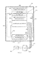
- FIG. 2 is a schematic view of an electric motor control system using thermoelectric cooling in accordance with an exemplary embodiment
- FIG. 3 is a schematic view of an electric motor control system using thermoelectric cooling in accordance with another exemplary embodiment.
- FIG. 4 is a schematic view of an electric motor control system using thermoelectric cooling in accordance with a further exemplary embodiment.
- FIG. 1 An example of a typical electric motor control system 100 is depicted in FIG. 1 .
- a motor controller 102 controls operation of an electric motor 104 which drives a load 106.
- the motor controller 102 includes controller electronics 108 coupled to the electric motor 104 by control lines 110 to control speed, torque, acceleration, and deceleration of the electric motor 104.
- kinetic energy of the load 106 is typically converted back into electrical energy by the electric motor 104 and passed as a braking current 112 on braking input 114 from the controller electronics 108 through a braking resistor 116 and back through braking return 118.
- Heat produced by dissipating the braking current 112 in the braking resistor 116 adds to total heat within the motor controller 102.
- a heat conduction path to ambient environment 120 provides a heat dissipation path for heat within the motor controller 102 to reach a cooler environment external to the motor controller 102.
- FIG. 2 is a schematic view of an electric motor control system 200 using thermoelectric cooling in accordance with an exemplary embodiment. Similar to the electric motor control system 100 of FIG. 1 , the electric motor control system 200 of FIG. 2 includes an electric motor controller 202 that controls operation of an electric motor 204 which drives a load 206. The electric motor controller 202 includes controller electronics 208 coupled to the electric motor 204 by control lines 210 to control speed, torque, acceleration, and deceleration of the electric motor 204. In the example of FIG.
- the cooling circuit 220 includes a thermoelectric cooler 224 coupled to a cooler electrical input 226 and a cooler electrical return 228.
- the braking circuit 216 is coupled to the cooler electrical input 226 and the cooler electrical return 228.
- the thermoelectric cooler 224 is configured to receive a braking current 230 associated with braking of the electric motor 204, where the braking circuit 216 receives the input braking current 212 from the controller electronics 208 and provides the braking current 230 to the thermoelectric cooler 224.
- the braking circuit 216 is absent a braking resistor such that the braking current 230 is equivalent to the input braking current 212.
- the braking circuit 216 includes a braking resistor 232.
- the braking resistor 232 may produce less heat than the braking resistor 116 of FIG. 1 .
- the braking circuit 216 may be configured to divide the input braking current 212 between the braking resistor 232 and the thermoelectric cooler 224.
- the braking resistor 232 can be configured in series with the thermoelectric cooler 224, such that the braking current 230 is equivalent to the input braking current 212.
- the controller electronics 208, the braking circuit 216, and the thermoelectric cooler 224 are located within a motor controller housing 242 of the electric motor controller 202.
- the electric motor controller 202 also includes a heat conduction path 234 that places the thermoelectric cooler 224 in thermal communication with the controller electronics 208.
- the heat conduction path 234 can be, for example, a cold plate. Heat flows from the controller electronics 208 through the heat conduction path 234 to a cold side 236 of the thermoelectric cooler 224. Heat may also flow from the braking circuit 216 through the heat conduction path 234 to the cold side 236 of the thermoelectric cooler 224.
- thermoelectric cooler 224 When all or a portion of the input braking current 212 is applied to the thermoelectric cooler 224 as braking current 230, the thermoelectric cooler 224 creates a thermal effect that causes heat to flow from the cold side 236 to a hot side 238 of the thermoelectric cooler 224.
- the hot side 238 of the thermoelectric cooler 224 has a heat conduction path 240 to an ambient environment external to the electric motor controller 202.
- the thermoelectric cooler 224 is an active electrically powered cooling device that can operate according to the Peltier effect in which an electrical input is transformed to a heat flux.
- Thermal electric materials of the thermoelectric cooler 224 may be bulk, quantum well or other electronic cooling materials.
- thermoelectric cooler 224 can include solid-state devices that use the Peltier effect to create a heat flux between junctions of two different types of materials, such that heat is transferred from the cold side 236 to the hot side 238 against a thermal gradient with the consumption of electrical energy.
- FIG. 3 is a schematic view of an electric motor control system 300 using thermoelectric cooling in accordance with another exemplary embodiment.
- the electric motor control system 300 of FIG. 3 is similar to the electric motor control system 200 of FIG. 2 , where like elements have like numbers.
- the electric motor control system 300 of FIG. 3 includes an electric motor controller 302 that controls operation of the electric motor 204 which drives the load 206.
- the electric motor controller 302 includes controller electronics 208 coupled to the electric motor 204 by control lines 210 to control speed, torque, acceleration, and deceleration of the electric motor 204.
- the electric motor control system 300 of FIG. 3 includes the braking circuit 216 electrically coupled to the controller electronics 208 by the braking input 214 and the braking return 218, as well as to the thermoelectric cooler 224 by the cooler electrical input 226 and the cooler electrical return 228.
- thermoelectric cooler 224 provides cooling for the controller electronics 208 through heat conduction paths 234 and 240 and cold and hot sides 236 and 238.
- the electric motor controller 302 includes a power logical-OR function 304 to provide power from the braking current 230 on the cooler electrical input 226 and/or from an external power supply 306.
- the external power supply 306 may be delivered from a source external to a motor controller housing 308 of the electric motor controller 302, such as an alternator/generator or a power bus accessible by the electric motor control system 300.
- the power logical-OR function 304 may be configured to draw current from the external power supply 306 when no/insufficient current is available from the braking current 230.
- the power logical-OR function 304 can be incorporated into the braking circuit 216, with the thermoelectric cooler 224, or can be a separate circuit.
- FIG. 4 is a schematic view of an electric motor control system 400 using thermoelectric cooling in accordance with a further exemplary embodiment.
- the electric motor control system 400 of FIG. 4 is similar to the electric motor control system 200 of FIG. 2 , where like elements have like numbers. Similar to the electric motor control system 200 of FIG. 2 , the electric motor control system 400 of FIG. 4 includes an electric motor controller 402 that controls operation of the electric motor 204 which drives the load 206.
- the electric motor controller 402 includes controller electronics 208 coupled to the electric motor 204 by control lines 210 to control speed, torque, acceleration, and deceleration of the electric motor 204. Also similar to FIG. 2 , the electric motor control system 400 of FIG.
- braking circuit 404 electrically coupled to the controller electronics 208 by the braking input 214 and the braking return 218, as well as to the thermoelectric cooler 224 by the cooler electrical input 226 and the cooler electrical return 228.
- the braking circuit 404 can be incorporated in the controller electronics 208.
- the thermoelectric cooler 224 provides cooling for the controller electronics 208 through heat conduction paths 234 and 240 and cold and hot sides 236 and 238.
- the braking circuit 404 includes an energy storage circuit 406 configured to store energy of the input braking current 212 and provide the braking current 230 to the thermoelectric cooler 224 over a period of time. Energy storage in the energy storage circuit 406 may be achieved using an ultra-capacitor or other storage element (not depicted). Also, similar to the braking circuit 216 of FIGS. 2 and 3 , the braking circuit 404 can include the braking resistor 232 of FIGS. 2 and 3 .
- the energy storage circuit 406 can be located external to the braking circuit 404.
- the electric motor controller 402 can also include a power logical-OR function, such as the power logical-OR function 304 of FIG. 3 , such that the thermoelectric cooler 224 can receive electric power from one or more of an external power supply and the braking circuit 404.
Landscapes
- Engineering & Computer Science (AREA)
- Power Engineering (AREA)
- Physics & Mathematics (AREA)
- Mechanical Engineering (AREA)
- Thermal Sciences (AREA)
- General Engineering & Computer Science (AREA)
- Motor Or Generator Cooling System (AREA)
- Stopping Of Electric Motors (AREA)
Abstract
Description
- This invention was made with Government support under Contract No. FA8650-06-D-2621 awarded by the United States Air Force. The Government may therefore have certain rights in this invention.
- The subject matter disclosed herein relates to electric motor braking and, more particularly, to electric motor braking using thermoelectric cooling.
- Many systems are designed to use a motor controller to control speed and torque of an electric motor. A shaft of the electric motor drives an inertial mass and an aiding or apposing torque of a load. When accelerating, the electric motor converts electrical energy into mechanical torque to accelerate the inertial mass of the load. When decelerating, kinetic energy of the load is typically converted back into electrical energy by the electric motor. If possible, all or some of the regenerated energy can be transferred back into a power system of the electric motor. If this transfer is not desired or the deceleration needs to be faster, a braking resistor is used. When a braking resistor is used, the regenerated energy is dissipated as heat. The heat created is wasted energy, which in turn, causes the motor controller to run hotter. To accommodate heating effects of the braking resistor, the size of passive cooling elements used to remove heat from the motor controller may have to be increased.
- In applications where the internal temperature of the motor controller is near the design limits of electronic components of the motor controller, life expectancy of the electronic components can be substantially reduced. Reducing heat in the motor controller can increase the reliability of the motor controller.
- According to one aspect of the invention, an electric motor controller includes controller electronics configured to control an electric motor. The electric motor controller also includes a thermoelectric cooler in the thermal path for the controller electronics. The thermoelectric cooler is configured to receive a braking current associated with braking of the electric motor and provide cooling to the controller electronics.
- According to another aspect of the invention, an electric motor control system includes an electric motor and an electric motor controller electrically coupled to the electric motor. The electric motor controller includes controller electronics configured to control the electric motor and also includes a thermoelectric cooler used to thermally cool the controller electronics. The electric motor controller further includes a braking circuit configured to receive an input braking current from the controller electronics associated with braking of the electric motor and provide a braking current to the thermoelectric cooler.
- According to a further aspect of the invention, a method of thermoelectric cooling in an electric motor controller is provided. The method includes receiving a braking current responsive to braking of an electric motor. The electric motor is controlled by controller electronics. The braking current is applied to a thermoelectric cooler in thermal communication with the controller electronics, thereby cooling the controller electronics.
- These and other advantages and features will become more apparent from the following description taken in conjunction with the drawings.
- The subject matter, which is regarded as the invention, is particularly pointed out and distinctly claimed in the claims at the conclusion of the specification. The foregoing and other features, and advantages of the invention are apparent from the following detailed description taken in conjunction with the accompanying drawings in which:
-
FIG. 1 is a schematic view of an electric motor control system in accordance with the prior art; -
FIG. 2 is a schematic view of an electric motor control system using thermoelectric cooling in accordance with an exemplary embodiment; -
FIG. 3 is a schematic view of an electric motor control system using thermoelectric cooling in accordance with another exemplary embodiment; and -
FIG. 4 is a schematic view of an electric motor control system using thermoelectric cooling in accordance with a further exemplary embodiment. - The detailed description explains embodiments of the invention, together with advantages and features, by way of example with reference to the drawings.
- An example of a typical electric
motor control system 100 is depicted inFIG. 1 . Amotor controller 102 controls operation of anelectric motor 104 which drives aload 106. Themotor controller 102 includescontroller electronics 108 coupled to theelectric motor 104 bycontrol lines 110 to control speed, torque, acceleration, and deceleration of theelectric motor 104. When decelerating theelectric motor 104, kinetic energy of theload 106 is typically converted back into electrical energy by theelectric motor 104 and passed as abraking current 112 onbraking input 114 from thecontroller electronics 108 through abraking resistor 116 and back throughbraking return 118. Heat produced by dissipating thebraking current 112 in thebraking resistor 116 adds to total heat within themotor controller 102. A heat conduction path toambient environment 120 provides a heat dissipation path for heat within themotor controller 102 to reach a cooler environment external to themotor controller 102. - In exemplary embodiments, by replacing all or part of the resistance of the
braking resistor 116 ofFIG. 1 with thermoelectric cooling components, braking heat generation may be decreased and heat dissipation accelerated.FIG. 2 is a schematic view of an electricmotor control system 200 using thermoelectric cooling in accordance with an exemplary embodiment. Similar to the electricmotor control system 100 ofFIG. 1 , the electricmotor control system 200 ofFIG. 2 includes anelectric motor controller 202 that controls operation of anelectric motor 204 which drives aload 206. Theelectric motor controller 202 includescontroller electronics 208 coupled to theelectric motor 204 bycontrol lines 210 to control speed, torque, acceleration, and deceleration of theelectric motor 204. In the example ofFIG. 2 , when decelerating theelectric motor 204, kinetic energy of theload 206 is converted back into electrical energy by theelectric motor 204 and passed as aninput braking current 212 onbraking input 214 from thecontroller electronics 208 through abraking circuit 216 and back throughbraking return 218. Although depicted separately, it will be understood that thebraking circuit 216 can be incorporated in thecontroller electronics 208. - An equivalent resistance of the
braking resistor 116 ofFIG. 1 is replaced in whole or in part with resistance of acooling circuit 220 inFIG. 2 . Thecooling circuit 220 includes athermoelectric cooler 224 coupled to a coolerelectrical input 226 and a coolerelectrical return 228. In the example ofFIG. 2 , thebraking circuit 216 is coupled to the coolerelectrical input 226 and the coolerelectrical return 228. Accordingly, thethermoelectric cooler 224 is configured to receive abraking current 230 associated with braking of theelectric motor 204, where thebraking circuit 216 receives theinput braking current 212 from thecontroller electronics 208 and provides thebraking current 230 to thethermoelectric cooler 224. In embodiments where thecooling circuit 220 has a resistance that is substantially equivalent to thebraking resistor 116 ofFIG. 1 , thebraking circuit 216 is absent a braking resistor such that thebraking current 230 is equivalent to theinput braking current 212. In embodiments where thecooling circuit 220 has a resistance that is less than thebraking resistor 116 ofFIG. 1 , thebraking circuit 216 includes abraking resistor 232. Thebraking resistor 232 may produce less heat than thebraking resistor 116 ofFIG. 1 . When thebraking circuit 216 includes thebraking resistor 232, thebraking circuit 216 may be configured to divide theinput braking current 212 between thebraking resistor 232 and thethermoelectric cooler 224. Alternatively, thebraking resistor 232 can be configured in series with thethermoelectric cooler 224, such that thebraking current 230 is equivalent to theinput braking current 212. - In the embodiment depicted in
FIG. 2 , thecontroller electronics 208, thebraking circuit 216, and thethermoelectric cooler 224 are located within amotor controller housing 242 of theelectric motor controller 202. Theelectric motor controller 202 also includes aheat conduction path 234 that places thethermoelectric cooler 224 in thermal communication with thecontroller electronics 208. Theheat conduction path 234 can be, for example, a cold plate. Heat flows from thecontroller electronics 208 through theheat conduction path 234 to acold side 236 of thethermoelectric cooler 224. Heat may also flow from thebraking circuit 216 through theheat conduction path 234 to thecold side 236 of thethermoelectric cooler 224. When all or a portion of theinput braking current 212 is applied to thethermoelectric cooler 224 as brakingcurrent 230, thethermoelectric cooler 224 creates a thermal effect that causes heat to flow from thecold side 236 to ahot side 238 of thethermoelectric cooler 224. Thehot side 238 of thethermoelectric cooler 224 has aheat conduction path 240 to an ambient environment external to theelectric motor controller 202. Thethermoelectric cooler 224 is an active electrically powered cooling device that can operate according to the Peltier effect in which an electrical input is transformed to a heat flux. Thermal electric materials of thethermoelectric cooler 224 may be bulk, quantum well or other electronic cooling materials. For example, thethermoelectric cooler 224 can include solid-state devices that use the Peltier effect to create a heat flux between junctions of two different types of materials, such that heat is transferred from thecold side 236 to thehot side 238 against a thermal gradient with the consumption of electrical energy. -
FIG. 3 is a schematic view of an electricmotor control system 300 using thermoelectric cooling in accordance with another exemplary embodiment. The electricmotor control system 300 ofFIG. 3 is similar to the electricmotor control system 200 ofFIG. 2 , where like elements have like numbers. Similar to the electricmotor control system 200 ofFIG. 2 , the electricmotor control system 300 ofFIG. 3 includes anelectric motor controller 302 that controls operation of theelectric motor 204 which drives theload 206. Theelectric motor controller 302 includescontroller electronics 208 coupled to theelectric motor 204 bycontrol lines 210 to control speed, torque, acceleration, and deceleration of theelectric motor 204. Also similar toFIG. 2 , the electricmotor control system 300 ofFIG. 3 includes thebraking circuit 216 electrically coupled to thecontroller electronics 208 by thebraking input 214 and thebraking return 218, as well as to thethermoelectric cooler 224 by the coolerelectrical input 226 and the coolerelectrical return 228. - In the example of
FIG. 3 , thethermoelectric cooler 224 provides cooling for thecontroller electronics 208 throughheat conduction paths hot sides FIG. 2 , which relies upon the braking current 230 from input braking current 212 to electrically power thethermoelectric cooler 224, theelectric motor controller 302 includes a power logical-OR function 304 to provide power from the braking current 230 on the coolerelectrical input 226 and/or from anexternal power supply 306. Theexternal power supply 306 may be delivered from a source external to amotor controller housing 308 of theelectric motor controller 302, such as an alternator/generator or a power bus accessible by the electricmotor control system 300. The power logical-OR function 304 may be configured to draw current from theexternal power supply 306 when no/insufficient current is available from the braking current 230. The power logical-OR function 304 can be incorporated into thebraking circuit 216, with thethermoelectric cooler 224, or can be a separate circuit. -
FIG. 4 is a schematic view of an electricmotor control system 400 using thermoelectric cooling in accordance with a further exemplary embodiment. The electricmotor control system 400 ofFIG. 4 is similar to the electricmotor control system 200 ofFIG. 2 , where like elements have like numbers. Similar to the electricmotor control system 200 ofFIG. 2 , the electricmotor control system 400 ofFIG. 4 includes anelectric motor controller 402 that controls operation of theelectric motor 204 which drives theload 206. Theelectric motor controller 402 includescontroller electronics 208 coupled to theelectric motor 204 bycontrol lines 210 to control speed, torque, acceleration, and deceleration of theelectric motor 204. Also similar toFIG. 2 , the electricmotor control system 400 ofFIG. 4 includes abraking circuit 404 electrically coupled to thecontroller electronics 208 by thebraking input 214 and thebraking return 218, as well as to thethermoelectric cooler 224 by the coolerelectrical input 226 and the coolerelectrical return 228. Although depicted separately, it will be understood that thebraking circuit 404 can be incorporated in thecontroller electronics 208. - In the example of
FIG. 4 , thethermoelectric cooler 224 provides cooling for thecontroller electronics 208 throughheat conduction paths hot sides FIG. 2 , thebraking circuit 404 includes anenergy storage circuit 406 configured to store energy of the input braking current 212 and provide the braking current 230 to thethermoelectric cooler 224 over a period of time. Energy storage in theenergy storage circuit 406 may be achieved using an ultra-capacitor or other storage element (not depicted). Also, similar to thebraking circuit 216 ofFIGS. 2 and3 , thebraking circuit 404 can include thebraking resistor 232 ofFIGS. 2 and3 . Additionally, although depicted as part of thebraking circuit 404, theenergy storage circuit 406 can be located external to thebraking circuit 404. As a further alternative, theelectric motor controller 402 can also include a power logical-OR function, such as the power logical-OR function 304 ofFIG. 3 , such that thethermoelectric cooler 224 can receive electric power from one or more of an external power supply and thebraking circuit 404. - While the invention has been described in detail in connection with only a limited number of embodiments, it should be readily understood that the invention is not limited to such disclosed embodiments. Rather, the invention can be modified to incorporate any number of variations, alterations, substitutions or equivalent arrangements not heretofore described, but which are commensurate with the spirit and scope of the invention. Additionally, while various embodiments of the invention have been described, it is to be understood that aspects of the invention may include only some of the described embodiments. Accordingly, the invention is not to be seen as limited by the foregoing description, but is only limited by the scope of the appended claims.
Claims (15)
- An electric motor controller (202) comprising:controller electronics (208) configured to control an electric motor (204); anda thermoelectric cooler (224) in thermal communication with the controller electronics (208) and configured to receive a braking current (212) associated with braking of the electric motor (204) and provide cooling to the controller electronics (208).
- The electric motor controller of claim 1, further comprising:a braking circuit (216) configured to receive an input braking current (212) from the controller electronics (208) and provide the braking current (230) to the thermoelectric cooler.
- An electric motor control system (200) comprising:an electric motor (204); andan electric motor controller (202) electrically coupled to the electric motor (204), the electric motor controller (202) comprising:controller electronics (208) configured to control the electric motor (204);a thermoelectric cooler (224) in thermal communication with the controller electronics; anda braking circuit (216) configured to receive an input braking current (212) from the controller electronics (208) associated with braking of the electric motor (204) and provide a braking current (230) to the thermoelectric cooler (224).
- The electric motor controller of claim 1 or the electric motor control system of claim 3, wherein a cold side of the thermoelectric cooler is thermally coupled to a heat conduction path from the controller electronics, and a hot side of the thermoelectric cooler is thermally coupled to a heat conduction path to an ambient environment.
- The electric motor controller of claim 2 or the electric motor control system of claim 3, wherein the braking circuit (216) comprises a braking resistor (232) and the braking circuit (216) is further configured to divide the input braking current (212) between the braking resistor (232) and the thermoelectric cooler (224).
- The electric motor controller of claim 2 or the electric motor control system of claim 3, further comprising:an external power supply electrically coupled to the thermoelectric cooler (224), wherein the thermoelectric cooler (224) is configured to receive electric power from one or more of the external power supply and the braking circuit (216).
- The electric motor control system (200) of claim 3, wherein the braking circuit (216), the thermoelectric cooler (224), and the controller electronics (208) are within a motor controller housing of the electric motor controller (202).
- The electric motor controller of claim 2 or the electric motor control system of claim 3, further comprising:an energy storage circuit configured to store energy of the input braking current (212) and provide the braking current (230) to the thermoelectric cooler (224) over a period of time.
- A method of thermoelectric cooling in an electric motor controller (202), the method comprising:receiving a braking current responsive to braking of an electric motor (204), the electric motor controlled by controller electronics; andapplying the braking current (230) to a thermoelectric cooler (224) in thermal communication with the controller electronics (208), thereby cooling the controller electronics (208).
- The method of claim 9, further comprising:thermally coupling a cold side of the thermoelectric cooler (224) to a heat conduction path from the controller electronics (208); andthermally coupling a hot side of the thermoelectric cooler (224) to a heat conduction path to an ambient environment.
- The method of claim 9, further comprising:receiving an input braking current (212) at a braking circuit from the controller electronics based on braking of the electric motor (204); andproviding the braking current (230) from the braking circuit (216) to the thermoelectric cooler (224).
- The method of claim 11, wherein the braking circuit (216) comprises a braking resistor, and the method further comprising:dividing the input braking current between the braking resistor (232) and the thermoelectric cooler (224).
- The method of claim 11, further comprising:providing the thermoelectric cooler with electric power from one or more of an external power supply and the braking circuit.
- The electric motor controller of claim 2 or the method of claim 16, wherein the braking circuit, the thermoelectric cooler (224), and the controller electronics (208) are within a motor controller housing.
- The method of claim 11, further comprising:storing energy of the input braking current (212); andproviding the braking current to the thermoelectric cooler (224) over a period of time.
Applications Claiming Priority (1)
| Application Number | Priority Date | Filing Date | Title |
|---|---|---|---|
| US13/645,850 US8975838B2 (en) | 2012-10-05 | 2012-10-05 | Electric motor braking using thermoelectric cooling |
Publications (3)
| Publication Number | Publication Date |
|---|---|
| EP2717463A2 true EP2717463A2 (en) | 2014-04-09 |
| EP2717463A3 EP2717463A3 (en) | 2017-04-26 |
| EP2717463B1 EP2717463B1 (en) | 2021-04-28 |
Family
ID=48906151
Family Applications (1)
| Application Number | Title | Priority Date | Filing Date |
|---|---|---|---|
| EP13178936.4A Active EP2717463B1 (en) | 2012-10-05 | 2013-08-01 | Electric motor braking using thermoelectric cooling |
Country Status (2)
| Country | Link |
|---|---|
| US (1) | US8975838B2 (en) |
| EP (1) | EP2717463B1 (en) |
Families Citing this family (5)
| Publication number | Priority date | Publication date | Assignee | Title |
|---|---|---|---|---|
| US12553648B2 (en) | 2008-01-28 | 2026-02-17 | Ambassador Asset Management Limited Partnership | Thermo-electric heat pump systems |
| FI123563B (en) * | 2012-09-04 | 2013-07-15 | Kone Corp | Procedure and system for increasing the capacity of a lift that is not used on a floor level |
| US10982883B1 (en) * | 2014-08-06 | 2021-04-20 | Ambassador Asset Management Limited Partnership | Portable active temperature controlled container comprising a cool sink |
| US10263497B2 (en) | 2016-01-29 | 2019-04-16 | Rockwell Automation Technologies, Inc. | System and method for active cooling of on-machine devices |
| US12313306B1 (en) | 2022-01-25 | 2025-05-27 | Ambassador Asset Management Limited | Portable thermoelectric adaptive environment system with intelligent power management |
Family Cites Families (24)
| Publication number | Priority date | Publication date | Assignee | Title |
|---|---|---|---|---|
| US4453114A (en) * | 1982-12-30 | 1984-06-05 | The Boeing Company | Electromechanical actuator counter-EMF utilization system |
| US5371665A (en) | 1994-03-14 | 1994-12-06 | Quisenberry; Tony M. | Power control circuit for improved power application and temperature control of thermoelectric coolers and method for controlling thereof |
| GB9924903D0 (en) * | 1999-10-22 | 1999-12-22 | Eaton Ltd | Cooling resistor banks |
| US6239502B1 (en) * | 1999-11-22 | 2001-05-29 | Bae Systems Controls | Phase change assisted heat sink |
| JP3366899B2 (en) | 2000-06-13 | 2003-01-14 | 東海旅客鉄道株式会社 | Regenerative brake |
| US6680596B1 (en) | 2002-10-10 | 2004-01-20 | S-B Power Tool Corporation | Electric motor having regenerative braking |
| DE10303719B4 (en) * | 2003-01-30 | 2006-06-14 | Siemens Ag | Diesel electric locomotive |
| US7338637B2 (en) * | 2003-01-31 | 2008-03-04 | Hewlett-Packard Development Company, L.P. | Microfluidic device with thin-film electronic devices |
| US7721855B2 (en) * | 2004-07-23 | 2010-05-25 | General Electric Company | Locomotive dynamic braking grid package configuration |
| US7109686B2 (en) * | 2004-11-15 | 2006-09-19 | Ise Corporation | System and method for precharging and discharging a high power ultracapacitor pack |
| US20070144800A1 (en) * | 2005-11-30 | 2007-06-28 | Stone Kevin T | System and method for braking resistor supplemental heating |
| US20080000381A1 (en) * | 2006-05-24 | 2008-01-03 | Bartley Thomas L | Rail car braking regeneration and propulsion system and method |
| EP2106380B1 (en) * | 2007-01-11 | 2011-12-28 | Otis Elevator Company | Thermoelectric thermal management system for the energy storage system in a regenerative elevator |
| US20080174174A1 (en) * | 2007-01-22 | 2008-07-24 | James S. Burns | Passive Truck Trailer Braking Regeneration and Propulsion System and Method |
| US20080266801A1 (en) * | 2007-04-30 | 2008-10-30 | Rockwell Automation Technologies, Inc. | Phase change cooled power electronic module |
| US7902957B2 (en) * | 2007-04-30 | 2011-03-08 | Rockwell Automation Technologies, Inc. | Phase change cooled electrical resistor |
| US20080266802A1 (en) * | 2007-04-30 | 2008-10-30 | Rockwell Automation Technologies, Inc. | Phase change cooled electrical connections for power electronic devices |
| US20080266803A1 (en) * | 2007-04-30 | 2008-10-30 | Rockwell Automation Technologies, Inc. | Phase change cooled electrical bus structure |
| US20100014219A1 (en) * | 2008-04-15 | 2010-01-21 | Julien Strack | Explosive Atmosphere Heat Dissipation System |
| US8035349B2 (en) * | 2008-09-30 | 2011-10-11 | Toyota Motor Engineering & Manufacturing North America, Inc. | Systems and methods for absorbing waste electricity from regenerative braking in hybridized vehicles |
| US20100090625A1 (en) * | 2008-10-09 | 2010-04-15 | Gm Global Technology Operations, Inc. | Automotive system and power converter assembly with a braking circuit |
| US8009393B2 (en) | 2009-09-08 | 2011-08-30 | Hamilton Sundstrand Corporation | Thermoelectric device utilized as voltage snubber |
| US8653358B2 (en) * | 2009-12-18 | 2014-02-18 | Hamilton Sunstrand Corporation | Thermoelectric device architecture |
| US8847524B2 (en) * | 2011-09-29 | 2014-09-30 | Siemens Industry, Inc. | Dissipation of the braking energy of electrically powered mining equipment by liquid-cooled braking resistors |
-
2012
- 2012-10-05 US US13/645,850 patent/US8975838B2/en active Active
-
2013
- 2013-08-01 EP EP13178936.4A patent/EP2717463B1/en active Active
Also Published As
| Publication number | Publication date |
|---|---|
| US20140097772A1 (en) | 2014-04-10 |
| US8975838B2 (en) | 2015-03-10 |
| EP2717463B1 (en) | 2021-04-28 |
| EP2717463A3 (en) | 2017-04-26 |
Similar Documents
| Publication | Publication Date | Title |
|---|---|---|
| EP2717463B1 (en) | Electric motor braking using thermoelectric cooling | |
| US10377264B2 (en) | Vehicle conductive charge port having cooling infrastructure | |
| US8875521B2 (en) | Device and method for cooling components using magnetizable phase-change material | |
| US10069180B2 (en) | Thermoelectric battery cooling system and method | |
| EP2680289A1 (en) | Contactor mounting panel with improved thermal characteristics | |
| US10443499B2 (en) | Enhanced heat sink availability on gas turbine engines through the use of coolers | |
| US10622686B2 (en) | Battery thermal management system including bimetallic member | |
| US9671172B2 (en) | Motor with cooled rotor | |
| JP2016513337A (en) | Thermoelectric based thermal management system | |
| EP2572992A1 (en) | Aircraft light | |
| US4453114A (en) | Electromechanical actuator counter-EMF utilization system | |
| US20160265855A1 (en) | Magnetic coupling for heat flow management in thermoelectric modules and devices thereof | |
| US20130215571A1 (en) | Semiconductor device and cooling system for semiconductor device | |
| EP3729528B1 (en) | Electrical module cooling through waste heat recovery | |
| CN118714826B (en) | Active cooling systems, servers and vehicles | |
| EP2389058B1 (en) | Thermal packaging of a motor controller for an auxiliary power unit | |
| US10295229B2 (en) | Thermoelectric cooling system | |
| US20120273183A1 (en) | Coolant pumping system for mobile electronic systems | |
| CN104912964B (en) | Electric actuator | |
| CN106285921B (en) | Cooling device for turbocharger actuator | |
| Ivanov et al. | Active Thermoelectric Cooling of Motorcycle Voltage Regulator Impelemented with a Peltier Element | |
| EP4210460A1 (en) | Powering sensor packages in moving platforms | |
| US11024921B2 (en) | Component insulation systems | |
| JP2007515784A (en) | Control mechanism | |
| US20060176667A1 (en) | Device for controlling fan speed |
Legal Events
| Date | Code | Title | Description |
|---|---|---|---|
| PUAI | Public reference made under article 153(3) epc to a published international application that has entered the european phase |
Free format text: ORIGINAL CODE: 0009012 |
|
| AK | Designated contracting states |
Kind code of ref document: A2 Designated state(s): AL AT BE BG CH CY CZ DE DK EE ES FI FR GB GR HR HU IE IS IT LI LT LU LV MC MK MT NL NO PL PT RO RS SE SI SK SM TR |
|
| AX | Request for extension of the european patent |
Extension state: BA ME |
|
| PUAL | Search report despatched |
Free format text: ORIGINAL CODE: 0009013 |
|
| AK | Designated contracting states |
Kind code of ref document: A3 Designated state(s): AL AT BE BG CH CY CZ DE DK EE ES FI FR GB GR HR HU IE IS IT LI LT LU LV MC MK MT NL NO PL PT RO RS SE SI SK SM TR |
|
| AX | Request for extension of the european patent |
Extension state: BA ME |
|
| RIC1 | Information provided on ipc code assigned before grant |
Ipc: H02P 3/00 20060101AFI20170317BHEP Ipc: H02P 3/12 20060101ALI20170317BHEP Ipc: F25B 21/02 20060101ALN20170317BHEP Ipc: H02P 3/22 20060101ALI20170317BHEP |
|
| STAA | Information on the status of an ep patent application or granted ep patent |
Free format text: STATUS: REQUEST FOR EXAMINATION WAS MADE |
|
| STAA | Information on the status of an ep patent application or granted ep patent |
Free format text: STATUS: EXAMINATION IS IN PROGRESS |
|
| 17P | Request for examination filed |
Effective date: 20171024 |
|
| RBV | Designated contracting states (corrected) |
Designated state(s): AL AT BE BG CH CY CZ DE DK EE ES FI FR GB GR HR HU IE IS IT LI LT LU LV MC MK MT NL NO PL PT RO RS SE SI SK SM TR |
|
| 17Q | First examination report despatched |
Effective date: 20171124 |
|
| RIC1 | Information provided on ipc code assigned before grant |
Ipc: H02P 3/12 20060101ALI20201008BHEP Ipc: F25B 21/02 20060101ALN20201008BHEP Ipc: H02P 3/22 20060101ALI20201008BHEP Ipc: H02P 3/00 20060101AFI20201008BHEP |
|
| GRAP | Despatch of communication of intention to grant a patent |
Free format text: ORIGINAL CODE: EPIDOSNIGR1 |
|
| STAA | Information on the status of an ep patent application or granted ep patent |
Free format text: STATUS: GRANT OF PATENT IS INTENDED |
|
| INTG | Intention to grant announced |
Effective date: 20201120 |
|
| RAP1 | Party data changed (applicant data changed or rights of an application transferred) |
Owner name: HAMILTON SUNDSTRAND CORPORATION |
|
| GRAS | Grant fee paid |
Free format text: ORIGINAL CODE: EPIDOSNIGR3 |
|
| GRAA | (expected) grant |
Free format text: ORIGINAL CODE: 0009210 |
|
| STAA | Information on the status of an ep patent application or granted ep patent |
Free format text: STATUS: THE PATENT HAS BEEN GRANTED |
|
| AK | Designated contracting states |
Kind code of ref document: B1 Designated state(s): AL AT BE BG CH CY CZ DE DK EE ES FI FR GB GR HR HU IE IS IT LI LT LU LV MC MK MT NL NO PL PT RO RS SE SI SK SM TR |
|
| REG | Reference to a national code |
Ref country code: GB Ref legal event code: FG4D |
|
| REG | Reference to a national code |
Ref country code: CH Ref legal event code: EP |
|
| REG | Reference to a national code |
Ref country code: AT Ref legal event code: REF Ref document number: 1388278 Country of ref document: AT Kind code of ref document: T Effective date: 20210515 |
|
| REG | Reference to a national code |
Ref country code: DE Ref legal event code: R096 Ref document number: 602013077130 Country of ref document: DE |
|
| REG | Reference to a national code |
Ref country code: IE Ref legal event code: FG4D |
|
| REG | Reference to a national code |
Ref country code: LT Ref legal event code: MG9D |
|
| REG | Reference to a national code |
Ref country code: AT Ref legal event code: MK05 Ref document number: 1388278 Country of ref document: AT Kind code of ref document: T Effective date: 20210428 |
|
| PG25 | Lapsed in a contracting state [announced via postgrant information from national office to epo] |
Ref country code: HR Free format text: LAPSE BECAUSE OF FAILURE TO SUBMIT A TRANSLATION OF THE DESCRIPTION OR TO PAY THE FEE WITHIN THE PRESCRIBED TIME-LIMIT Effective date: 20210428 Ref country code: BG Free format text: LAPSE BECAUSE OF FAILURE TO SUBMIT A TRANSLATION OF THE DESCRIPTION OR TO PAY THE FEE WITHIN THE PRESCRIBED TIME-LIMIT Effective date: 20210728 Ref country code: AT Free format text: LAPSE BECAUSE OF FAILURE TO SUBMIT A TRANSLATION OF THE DESCRIPTION OR TO PAY THE FEE WITHIN THE PRESCRIBED TIME-LIMIT Effective date: 20210428 Ref country code: LT Free format text: LAPSE BECAUSE OF FAILURE TO SUBMIT A TRANSLATION OF THE DESCRIPTION OR TO PAY THE FEE WITHIN THE PRESCRIBED TIME-LIMIT Effective date: 20210428 Ref country code: NL Free format text: LAPSE BECAUSE OF FAILURE TO SUBMIT A TRANSLATION OF THE DESCRIPTION OR TO PAY THE FEE WITHIN THE PRESCRIBED TIME-LIMIT Effective date: 20210428 Ref country code: FI Free format text: LAPSE BECAUSE OF FAILURE TO SUBMIT A TRANSLATION OF THE DESCRIPTION OR TO PAY THE FEE WITHIN THE PRESCRIBED TIME-LIMIT Effective date: 20210428 |
|
| PG25 | Lapsed in a contracting state [announced via postgrant information from national office to epo] |
Ref country code: ES Free format text: LAPSE BECAUSE OF FAILURE TO SUBMIT A TRANSLATION OF THE DESCRIPTION OR TO PAY THE FEE WITHIN THE PRESCRIBED TIME-LIMIT Effective date: 20210428 Ref country code: PT Free format text: LAPSE BECAUSE OF FAILURE TO SUBMIT A TRANSLATION OF THE DESCRIPTION OR TO PAY THE FEE WITHIN THE PRESCRIBED TIME-LIMIT Effective date: 20210830 Ref country code: NO Free format text: LAPSE BECAUSE OF FAILURE TO SUBMIT A TRANSLATION OF THE DESCRIPTION OR TO PAY THE FEE WITHIN THE PRESCRIBED TIME-LIMIT Effective date: 20210728 Ref country code: PL Free format text: LAPSE BECAUSE OF FAILURE TO SUBMIT A TRANSLATION OF THE DESCRIPTION OR TO PAY THE FEE WITHIN THE PRESCRIBED TIME-LIMIT Effective date: 20210428 Ref country code: LV Free format text: LAPSE BECAUSE OF FAILURE TO SUBMIT A TRANSLATION OF THE DESCRIPTION OR TO PAY THE FEE WITHIN THE PRESCRIBED TIME-LIMIT Effective date: 20210428 Ref country code: GR Free format text: LAPSE BECAUSE OF FAILURE TO SUBMIT A TRANSLATION OF THE DESCRIPTION OR TO PAY THE FEE WITHIN THE PRESCRIBED TIME-LIMIT Effective date: 20210729 Ref country code: IS Free format text: LAPSE BECAUSE OF FAILURE TO SUBMIT A TRANSLATION OF THE DESCRIPTION OR TO PAY THE FEE WITHIN THE PRESCRIBED TIME-LIMIT Effective date: 20210828 Ref country code: SE Free format text: LAPSE BECAUSE OF FAILURE TO SUBMIT A TRANSLATION OF THE DESCRIPTION OR TO PAY THE FEE WITHIN THE PRESCRIBED TIME-LIMIT Effective date: 20210428 Ref country code: RS Free format text: LAPSE BECAUSE OF FAILURE TO SUBMIT A TRANSLATION OF THE DESCRIPTION OR TO PAY THE FEE WITHIN THE PRESCRIBED TIME-LIMIT Effective date: 20210428 |
|
| REG | Reference to a national code |
Ref country code: NL Ref legal event code: MP Effective date: 20210428 |
|
| PG25 | Lapsed in a contracting state [announced via postgrant information from national office to epo] |
Ref country code: SK Free format text: LAPSE BECAUSE OF FAILURE TO SUBMIT A TRANSLATION OF THE DESCRIPTION OR TO PAY THE FEE WITHIN THE PRESCRIBED TIME-LIMIT Effective date: 20210428 Ref country code: SM Free format text: LAPSE BECAUSE OF FAILURE TO SUBMIT A TRANSLATION OF THE DESCRIPTION OR TO PAY THE FEE WITHIN THE PRESCRIBED TIME-LIMIT Effective date: 20210428 Ref country code: EE Free format text: LAPSE BECAUSE OF FAILURE TO SUBMIT A TRANSLATION OF THE DESCRIPTION OR TO PAY THE FEE WITHIN THE PRESCRIBED TIME-LIMIT Effective date: 20210428 Ref country code: DK Free format text: LAPSE BECAUSE OF FAILURE TO SUBMIT A TRANSLATION OF THE DESCRIPTION OR TO PAY THE FEE WITHIN THE PRESCRIBED TIME-LIMIT Effective date: 20210428 Ref country code: CZ Free format text: LAPSE BECAUSE OF FAILURE TO SUBMIT A TRANSLATION OF THE DESCRIPTION OR TO PAY THE FEE WITHIN THE PRESCRIBED TIME-LIMIT Effective date: 20210428 Ref country code: RO Free format text: LAPSE BECAUSE OF FAILURE TO SUBMIT A TRANSLATION OF THE DESCRIPTION OR TO PAY THE FEE WITHIN THE PRESCRIBED TIME-LIMIT Effective date: 20210428 |
|
| REG | Reference to a national code |
Ref country code: DE Ref legal event code: R097 Ref document number: 602013077130 Country of ref document: DE |
|
| PLBE | No opposition filed within time limit |
Free format text: ORIGINAL CODE: 0009261 |
|
| STAA | Information on the status of an ep patent application or granted ep patent |
Free format text: STATUS: NO OPPOSITION FILED WITHIN TIME LIMIT |
|
| REG | Reference to a national code |
Ref country code: CH Ref legal event code: PL |
|
| PG25 | Lapsed in a contracting state [announced via postgrant information from national office to epo] |
Ref country code: MC Free format text: LAPSE BECAUSE OF FAILURE TO SUBMIT A TRANSLATION OF THE DESCRIPTION OR TO PAY THE FEE WITHIN THE PRESCRIBED TIME-LIMIT Effective date: 20210428 |
|
| 26N | No opposition filed |
Effective date: 20220131 |
|
| REG | Reference to a national code |
Ref country code: BE Ref legal event code: MM Effective date: 20210831 |
|
| PG25 | Lapsed in a contracting state [announced via postgrant information from national office to epo] |
Ref country code: LI Free format text: LAPSE BECAUSE OF NON-PAYMENT OF DUE FEES Effective date: 20210831 Ref country code: CH Free format text: LAPSE BECAUSE OF NON-PAYMENT OF DUE FEES Effective date: 20210831 |
|
| PG25 | Lapsed in a contracting state [announced via postgrant information from national office to epo] |
Ref country code: IS Free format text: LAPSE BECAUSE OF FAILURE TO SUBMIT A TRANSLATION OF THE DESCRIPTION OR TO PAY THE FEE WITHIN THE PRESCRIBED TIME-LIMIT Effective date: 20210828 Ref country code: LU Free format text: LAPSE BECAUSE OF NON-PAYMENT OF DUE FEES Effective date: 20210801 Ref country code: AL Free format text: LAPSE BECAUSE OF FAILURE TO SUBMIT A TRANSLATION OF THE DESCRIPTION OR TO PAY THE FEE WITHIN THE PRESCRIBED TIME-LIMIT Effective date: 20210428 |
|
| PG25 | Lapsed in a contracting state [announced via postgrant information from national office to epo] |
Ref country code: IT Free format text: LAPSE BECAUSE OF FAILURE TO SUBMIT A TRANSLATION OF THE DESCRIPTION OR TO PAY THE FEE WITHIN THE PRESCRIBED TIME-LIMIT Effective date: 20210428 Ref country code: IE Free format text: LAPSE BECAUSE OF NON-PAYMENT OF DUE FEES Effective date: 20210801 Ref country code: BE Free format text: LAPSE BECAUSE OF NON-PAYMENT OF DUE FEES Effective date: 20210831 |
|
| PG25 | Lapsed in a contracting state [announced via postgrant information from national office to epo] |
Ref country code: HU Free format text: LAPSE BECAUSE OF FAILURE TO SUBMIT A TRANSLATION OF THE DESCRIPTION OR TO PAY THE FEE WITHIN THE PRESCRIBED TIME-LIMIT; INVALID AB INITIO Effective date: 20130801 |
|
| P01 | Opt-out of the competence of the unified patent court (upc) registered |
Effective date: 20230522 |
|
| PG25 | Lapsed in a contracting state [announced via postgrant information from national office to epo] |
Ref country code: CY Free format text: LAPSE BECAUSE OF FAILURE TO SUBMIT A TRANSLATION OF THE DESCRIPTION OR TO PAY THE FEE WITHIN THE PRESCRIBED TIME-LIMIT Effective date: 20210428 |
|
| PG25 | Lapsed in a contracting state [announced via postgrant information from national office to epo] |
Ref country code: MK Free format text: LAPSE BECAUSE OF FAILURE TO SUBMIT A TRANSLATION OF THE DESCRIPTION OR TO PAY THE FEE WITHIN THE PRESCRIBED TIME-LIMIT Effective date: 20210428 |
|
| PG25 | Lapsed in a contracting state [announced via postgrant information from national office to epo] |
Ref country code: MT Free format text: LAPSE BECAUSE OF FAILURE TO SUBMIT A TRANSLATION OF THE DESCRIPTION OR TO PAY THE FEE WITHIN THE PRESCRIBED TIME-LIMIT Effective date: 20210428 |
|
| PGFP | Annual fee paid to national office [announced via postgrant information from national office to epo] |
Ref country code: DE Payment date: 20250724 Year of fee payment: 13 |
|
| PGFP | Annual fee paid to national office [announced via postgrant information from national office to epo] |
Ref country code: GB Payment date: 20250724 Year of fee payment: 13 |
|
| PGFP | Annual fee paid to national office [announced via postgrant information from national office to epo] |
Ref country code: FR Payment date: 20250723 Year of fee payment: 13 |
|
| PG25 | Lapsed in a contracting state [announced via postgrant information from national office to epo] |
Ref country code: TR Free format text: LAPSE BECAUSE OF FAILURE TO SUBMIT A TRANSLATION OF THE DESCRIPTION OR TO PAY THE FEE WITHIN THE PRESCRIBED TIME-LIMIT Effective date: 20210428 |