EP2717420A1 - Charging and discharging device and terminal - Google Patents
Charging and discharging device and terminal Download PDFInfo
- Publication number
- EP2717420A1 EP2717420A1 EP13789694.0A EP13789694A EP2717420A1 EP 2717420 A1 EP2717420 A1 EP 2717420A1 EP 13789694 A EP13789694 A EP 13789694A EP 2717420 A1 EP2717420 A1 EP 2717420A1
- Authority
- EP
- European Patent Office
- Prior art keywords
- charging
- discharging
- battery
- discharging apparatus
- interface
- Prior art date
- Legal status (The legal status is an assumption and is not a legal conclusion. Google has not performed a legal analysis and makes no representation as to the accuracy of the status listed.)
- Withdrawn
Links
Images



Classifications
-
- H—ELECTRICITY
- H02—GENERATION; CONVERSION OR DISTRIBUTION OF ELECTRIC POWER
- H02J—ELECTRIC POWER NETWORKS; CIRCUIT ARRANGEMENTS OR SYSTEMS FOR SUPPLYING OR DISTRIBUTING ELECTRIC POWER; SYSTEMS FOR STORING ELECTRIC ENERGY
- H02J7/00—Circuit arrangements for charging or discharging batteries or for supplying loads from batteries
-
- H—ELECTRICITY
- H02—GENERATION; CONVERSION OR DISTRIBUTION OF ELECTRIC POWER
- H02J—ELECTRIC POWER NETWORKS; CIRCUIT ARRANGEMENTS OR SYSTEMS FOR SUPPLYING OR DISTRIBUTING ELECTRIC POWER; SYSTEMS FOR STORING ELECTRIC ENERGY
- H02J7/00—Circuit arrangements for charging or discharging batteries or for supplying loads from batteries
- H02J7/865—Battery or charger load switching, e.g. concurrent charging and load supply
-
- H—ELECTRICITY
- H02—GENERATION; CONVERSION OR DISTRIBUTION OF ELECTRIC POWER
- H02J—ELECTRIC POWER NETWORKS; CIRCUIT ARRANGEMENTS OR SYSTEMS FOR SUPPLYING OR DISTRIBUTING ELECTRIC POWER; SYSTEMS FOR STORING ELECTRIC ENERGY
- H02J7/00—Circuit arrangements for charging or discharging batteries or for supplying loads from batteries
- H02J7/34—Parallel operation in networks using both storage and other DC sources, e.g. providing buffering
- H02J7/342—The other DC source being a battery actively interacting with the first one, i.e. battery to battery charging
-
- Y—GENERAL TAGGING OF NEW TECHNOLOGICAL DEVELOPMENTS; GENERAL TAGGING OF CROSS-SECTIONAL TECHNOLOGIES SPANNING OVER SEVERAL SECTIONS OF THE IPC; TECHNICAL SUBJECTS COVERED BY FORMER USPC CROSS-REFERENCE ART COLLECTIONS [XRACs] AND DIGESTS
- Y02—TECHNOLOGIES OR APPLICATIONS FOR MITIGATION OR ADAPTATION AGAINST CLIMATE CHANGE
- Y02E—REDUCTION OF GREENHOUSE GAS [GHG] EMISSIONS, RELATED TO ENERGY GENERATION, TRANSMISSION OR DISTRIBUTION
- Y02E60/00—Enabling technologies; Technologies with a potential or indirect contribution to GHG emissions mitigation
- Y02E60/10—Energy storage using batteries
Definitions
- the present utility model relates to the field of electronic devices, and in particular, to a charging and discharging apparatus and a terminal.
- Embodiments of the present utility model provide a charging and discharging apparatus and a terminal to implement mutual charging, thereby improving user experience.
- a charging and discharging apparatus including:
- the interface shell includes at least one pin and at least one socket, where the pin is configured to package the current output end of the charging and discharging circuit, and the socket is configured to package the current input end of the charging and discharging circuit; and that the current input end is configured to be connected to the current output end of the second charging and discharging apparatus includes:
- the interface shell further includes a connector; the connector is configured to package the battery connection end of the charging and discharging circuit; and that one end of the interface wire for external connection is electrically connected to the battery connection end includes:
- the pin and the socket of the charging and discharging interface match each other.
- the pin is a convex pin
- the socket is a concave socket
- a shape of the convex pin matches a shape of the concave socket.
- the interface shell includes two bottom faces and at least three side faces, and the connector, the pin, and the socket are provided on the side faces separately.
- a terminal including:
- the charging and discharging apparatus and the terminal provided in embodiments of the present utility model include the charging and discharging interface and the interface wire for external connection in the charging and discharging apparatus, where the charging and discharging interface includes a battery connection end, a current input end, and a current output end; one end of the interface wire for external connection is electrically connected to the battery connection end, and the other end is electrically connected to a battery of a first terminal; the current input end is configured to be connected to a current output end of a second charging and discharging apparatus, so as to charge the battery of the first battery; the second charging and discharging apparatus is electrically connected to a second terminal; the current output end is configured to be connected to a current input end of the second charging and discharging apparatus, so as to output electric energy in the battery of the first battery.
- the technical solutions of the present utility model under the circumstances that no additional part and no change in a terminal design are needed for adjusting discharging and charging, implement
- a charging and discharging apparatus 10 includes a charging and discharging interface 11 and a interface wire 12 for external connection, where the charging and discharging interface includes an interface shell 111 and a charging and discharging circuit 112 provided in the interface shell 111; the charging and discharging circuit 112 includes a battery connection end 1121, a current input end 1122, and a current output end 1123; one end of the interface wire 12 for external connection is electrically connected to the battery connection end 1121, and the other end is electrically connected to a battery of a first terminal 13; the current input end 1122 is configured to be connected to a current output end 2123 of a second charging and discharging apparatus 20, so as to charge the first terminal 13 battery; the second charging and discharging apparatus 20 is electrically connected to a second terminal 23. As shown in FIG. 1B , the current output end 1123 is configured to be connected to a current input end 2122 of the second charging and discharging apparatus 20, so
- the charging and discharging circuit 112 thereof is specifically shown in FIG. 2 .
- An existing charging and discharging circuit may be used to implement electric energy conversion and transmission, where ends A and B are current input ends, ends C and D are current output ends, and ends E and F are battery connection ends.
- the displayed charging and discharging circuit may be in other circuit forms as long as electric energy conversion and transmission is implemented.
- the present utility model sets no specific limitation thereto.
- the interface shell 111 includes at least one pin 1111 and at least one socket 1112, where the pin 1111 is configured to package the current output end 1123 of the charging and discharging circuit 112; the socket 1112 is configured to package the current input end 1122 of the charging and discharging circuit 112; that the current input end 1122 is configured to be connected to the current output end 2123 of the second charging and discharging apparatus 20 includes: the socket 1112 of the charging and discharging apparatus 10 configured to be connected to a pin 2111 of the second charging and discharging apparatus 20; and that the current output end 1123 is configured to be connected to the current input end 1122 of the second charging and discharging apparatus 20 includes: the pin 1111 of the charging and discharging apparatus 10 is configured to be inserted into a socket 2112 of the second charging and discharging apparatus 20.
- the interface shell shown in FIG. 3A or FIG. 3B is configured to package the charging and discharging circuit disposed inside the interface shell shown in FIG. 2 .
- the interface shell 111 further includes a connector 1113, where the connector 1113 is configured to package the battery connection end 1121 of the charging and discharging apparatus 10; and that one end of the interface wire 12 for external connection is electrically connected to the battery connection end 1121 includes: the one end of the interface wire 12 for external connection being electrically connected to the battery connection end 1121 through the connector 1113.
- a shape of the interface shell 111 of the charging and discharging interface 11 of the charging and discharging apparatus 10 includes a pentahedron, a hexahedron, and the like. It should be noted that the shape of the interface shell 111 of the charging and discharging interface 11 of the charging and discharging apparatus 10 may also be other regular shapes or irregular polyhedron, polygon, spherical shape, and the like.
- the utility model sets no limitation thereto.
- the interface shell 111 includes two bottom faces and at least three side faces, and the connector 1113, the pin 1111, and the socket 1112 are disposed on the side faces separately.
- the pin 1111 and the socket 1112 of the charging and discharging interface 11 match each other.
- the shape of the interface shell 111 of the charging and discharging interface 11 of the charging and discharging apparatus 10 that is electrically connected to the first terminal 12 is different from a shape of an interface shell 211 of a charging and discharging interface 21 of the charging and discharging apparatus 20 that is electrically connected to the second terminal 23, it is allowed as long as it is ensured that the pin 1111 on the interface shell 111 of the charging and discharging interface 11 of the charging and discharging apparatus 10 that is electrically connected to the first terminal 13 matches the socket 2112 on the charging and discharging apparatus 20 that is connected to the second terminal 23, or the socket 1112 on the charging and discharging apparatus 10 that is electrically connected to the first terminal 13 matches the pin 2111 on the charging and discharging apparatus 20 that is connected to the second terminal 23.
- the present utility model sets no limitation to specific shapes thereof.
- the pin 1111 is a convex pin
- the socket 1112 is a concave socket
- a shape of the convex pin 1111 matches a shape of the concave socket 1112.
- the same charging and discharging apparatuses may be electrically to the first terminal 13 and the second terminal 23 to realize mutual charging between the first terminal and the second terminal. Specifically: when the first terminal 13 charges the second terminal 23, the pin of the charging and discharging apparatus connected to the first terminal 13 is inserted into the socket of the charging and discharging apparatus connected to the second terminal 23.
- the charging and discharging apparatuses connected to the two terminals are the same, when it is necessary for the second terminal 23 to charge the first terminal 13, only a connection manner of the two charging and discharging apparatuses needs to be changed, that is, the pin of the charging and discharging apparatus connected to the second terminal 23 is inserted into the socket of the charging and discharging apparatus connected to the first terminal 13, and it is unnecessary to replace the charging and discharging apparatuses connected to the two terminals.
- the shape of the pin 1111 further includes a semi-circle shape, square wave shape, triangle shape, and the like; and the shape of the socket 1112 is a concave semi-circle shape, square wave shape, triangle shape, and the like that may be connected to or match the shape of the pin 1111.
- the pin is a convex pin 1111; the socket is a concave socket 1112; the interface shell 111 includes two pins 1111; and the convex pins 1111 of the charging and discharging apparatus 10 electrically connected to the first terminal 13 are inserted into concave sockets 2112 of the charging and discharging apparatus 20 electrically connected to the second terminal 23.
- the pin is a convex pin 1111; the socket is a concave socket 1112; the interface shell 111 includes two pins 1111; and convex pins 2111 of the charging and discharging apparatus 20 electrically connected to the second terminal 23 are connected to the concave sockets 1112 of the charging and discharging apparatus 10 electrically connected to the first terminal 13.
- connection mode shown in FIG. 6A implements a process of charging the second terminal 23 by the first terminal 13
- connection manner shown in FIG. 6B implements a process of charging the first terminal 13 by the second terminal 23. That is, different interface insertion and connection manners are used to implement a process of providing charging for the second terminal 23 by the first terminal 13 or a process of providing charging for the first terminal 13 by the second terminal 23.
- the charging and discharging apparatus 10 connected to the first terminal 13 may charge the second terminal 23 and a third terminal 33 simultaneously, thereby realizing one-to-many charging. If the charging and discharging apparatus 10 has three or four pins, the charging and discharging apparatus 10 may be used to implement charging for three or four devices at the same time. It should be noted that the charging and discharging apparatus 10 may have a plurality of pins 1111. In such cases, considering the appearance and practicability of the charging and discharging apparatus, the number of pins 1111 may be set in combination with the shape of the charging and discharging apparatus 10. The embodiment of the utility model sets no specific limitation to the number of pins 1111.
- the shape of the interface shell of the charging and discharging interface of the charging and discharging apparatus 10 is a rectangle
- the pin 1111 is a triangle
- the socket 1112 is a concave triangle matching the pin 1111.
- the interface shell 111 of the charging and discharging interface 11 of the charging and discharging apparatus 10 may include two pins 1111, one socket 1112, and one connector 1113, which are disposed on 4 side faces of the rectangle interface shell separately.
- the interface shell 111 of the charging and discharging apparatus 11 of the charging and discharging apparatus 10 is a circle
- the pin 1111 is a rectangle
- the socket 1112 is a concave rectangle matching the pin 1111.
- the interface shell 111 of the charging and discharging interface 11 of the charging and discharging apparatus 10 is a circle, it may include two pins 1111, one socket 1112, and one connector 1113, which are evenly disposed on a side face of the circle interface shell.
- pins 1111 there may be one, two, or more pins 1111. It should be noted that the number of pins 1111 and the shape and design of the interface shell 111 of the charging and discharging interface 11 of the charging and discharging apparatus 10 are related to user requirements. The present utility model sets no limitation to the number of pins 1111.
- the first terminal 13 and the second terminal 23 are mobile phones; and the interface wire 12 for external connection may electrically connect the charging and discharging apparatus 10 to a battery of the mobile phone through an interface for hanging decoration designed originally on the mobile phone, thereby realizing a charging process.
- first terminal 13 and the second terminal 23 are personal digital assistants PDA or tablet computers, and the like.
- the utility model sets no limitation thereto.
- the charging and discharging apparatus includes the charging and discharging interface and the interface wire for external connection in the charging and discharging apparatus, where the charging and discharging interface includes a battery connection end, a current input end, and a current output end; one end of the interface wire for external connection is electrically connected to the battery connection end, and the other end is electrically connected to a battery of a first terminal; the current input end is configured to be connected to a current output end of a second charging and discharging apparatus, so as to charge the battery of the first battery; the second charging and discharging apparatus is electrically connected to a second terminal; the current output end is configured to be connected to a current input end of the second charging and discharging apparatus, so as to output electric energy in the battery of the first battery.
- the technical solutions of the present utility model realize mutual charging under the circumstances that no additional part and no change in a terminal design are needed for adjusting discharging and charging, thereby
- the present utility model provides a terminal 100, including a terminal body 101, a battery 102, and a charging and discharging apparatus 103, where the charging and discharging apparatus 103 is the charging and discharging apparatus shown in any one of FIG. 1 to FIG. 9 ; the battery 102 is disposed inside the terminal body 101, and configured to electrically connect a battery connection end 10321 of a charging and discharging circuit 1032 in the charging and discharging apparatus through an interface wire for external connection 1031 in the charging and discharging apparatus 103.
- charging and discharging processes between the first terminal and the second terminal may be the specific charging and discharging processes described in the above charging and discharging apparatus, which are not described repeatedly in this embodiment.
- the terminal provided in embodiments of the present utility model includes the charging and discharging interface and the interface wire for external connection in the charging and discharging apparatus, where the charging and discharging interface includes a battery connection end, a current input end, and a current output end; one end of the interface wire for external connection is electrically connected to the battery connection end, and the other end is electrically connected to a battery of a first terminal; the current input end is configured to be connected to a current output end of a second charging and discharging apparatus, so as to charge the battery of the first battery; the second charging and discharging apparatus is electrically connected to a second terminal; the current output end is configured to be connected to a current input end of the second charging and discharging apparatus, so as to output electric energy in the battery of the first battery.
- the technical solutions of the present utility model realize mutual charging under the circumstances that no additional part and no change in a terminal design are needed for adjusting discharging and charging, thereby improving user experience.
Landscapes
- Engineering & Computer Science (AREA)
- Power Engineering (AREA)
- Charge And Discharge Circuits For Batteries Or The Like (AREA)
Abstract
Description
- This application claims priority to Chinese Patent Application No.
201220313466.3 - The present utility model relates to the field of electronic devices, and in particular, to a charging and discharging apparatus and a terminal.
- With the continuous improvement of a mobile phone performance, power consumption of the mobile phone also increases proportionally. The battery of a large-screen touch mobile phone usually lasts less than one day, and consequently an important phone call or schedule may easily be missed. As a result, under the circumstances of the original battery capacity of the mobile phone and no standby battery, to solve the problem of running out of the battery of the mobile phone, at present, there appears in th industry some solutions of a replaceable dry battery, such as a digital mate, and an external power source, such as on-the-go terminal-sharing battery wiring,.
- However, these technologies need additional parts and need changes in an original appearance of the mobile phone. In particular, for the on-the-go terminal-sharing battery wiring, a charging circuit design needs to be integrated on a terminal side and discharging or charging needs to be adjusted by changing the terminal design. This brings inconvenience to a user in using, thereby affecting user experience.
- Embodiments of the present utility model provide a charging and discharging apparatus and a terminal to implement mutual charging, thereby improving user experience.
- To achieve the above objective, embodiments of the present utility model use the following technical solutions:
- A charging and discharging apparatus is provided, including:
- including a charging and discharging interface and an interface wire for external connection, where the charging and discharging interface includes an interface shell and a charging and discharging circuit disposed inside the interface shell, where
- the charging and discharging circuit includes a battery connection end, a current input end, and a current output end; where one end of the interface wire for external connection is electrically connected to the battery connection end, and the other end is electrically connected to a battery of a first terminal; the current input end is configured to be connected to a current output end of a second charging and discharging apparatus to charge the battery of the first battery, the second charging and discharging apparatus is electrically connected to a second terminal; and the current output end is configured to be connected to a current input end of the second charging and discharging apparatus to output electric energy in the battery of the first battery.
- The interface shell includes at least one pin and at least one socket, where
the pin is configured to package the current output end of the charging and discharging circuit, and the socket is configured to package the current input end of the charging and discharging circuit; and
that the current input end is configured to be connected to the current output end of the second charging and discharging apparatus includes: - the socket of the charging and discharging apparatus configured to be connected to a pin of the second charging and discharging apparatus; and
- that the current output end is configured to be connected to the current input end of the second charging and discharging apparatus includes:
- the pin of the charging and discharging apparatus configured to be inserted into a socket of the second charging and discharging apparatus.
- The interface shell further includes a connector;
the connector is configured to package the battery connection end of the charging and discharging circuit; and
that one end of the interface wire for external connection is electrically connected to the battery connection end includes: - one end of the interface wire for external connection being electrically connected to the battery connection end through the connector.
- The pin and the socket of the charging and discharging interface match each other.
- The pin is a convex pin, and the socket is a concave socket.
- A shape of the convex pin matches a shape of the concave socket.
- The interface shell includes two bottom faces and at least three side faces, and the connector, the pin, and the socket are provided on the side faces separately.
- A terminal is provided, including:
- a terminal body, a battery, and a charging and discharging apparatus, where the charging and discharging apparatus is a charging and discharging apparatus according to claims 1 to 6;
- the battery is disposed inside the terminal body, and configured to electrically connect a battery connection end of a charging and discharging circuit in the charging and discharging apparatus through an interface wire for external connection in the charging and discharging apparatus.
- The charging and discharging apparatus and the terminal provided in embodiments of the present utility model include the charging and discharging interface and the interface wire for external connection in the charging and discharging apparatus, where the charging and discharging interface includes a battery connection end, a current input end, and a current output end; one end of the interface wire for external connection is electrically connected to the battery connection end, and the other end is electrically connected to a battery of a first terminal; the current input end is configured to be connected to a current output end of a second charging and discharging apparatus, so as to charge the battery of the first battery; the second charging and discharging apparatus is electrically connected to a second terminal; the current output end is configured to be connected to a current input end of the second charging and discharging apparatus, so as to output electric energy in the battery of the first battery. For the on-the-go terminal-sharing battery wiring in the prior art, the technical solutions of the present utility model, under the circumstances that no additional part and no change in a terminal design are needed for adjusting discharging and charging, implement mutual charging, thereby improving user experience.
- To describe the technical solutions in the embodiments of the present utility model or in the prior art more clearly, the following briefly introduces the accompanying drawings for describing the embodiments or the prior art. Apparently, the accompanying drawings in the following description show merely some embodiments of the present utility model, and persons of ordinary skill in the art may still derive other drawings from the accompanying drawings without creative efforts.
-
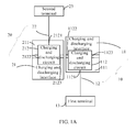
FIG. 1A is a schematic diagram of a charging and discharging apparatus according to an embodiment of the present utility model; -
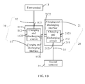
FIG. 1B is another schematic diagram of a charging and discharging apparatus according to an embodiment of the present utility model; -
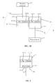
FIG. 2 is another schematic diagram of a charging and discharging apparatus according to an embodiment of the present utility model; -
FIG. 3A is another schematic diagram of a charging and discharging apparatus according to an embodiment of the present utility model; -
FIG. 3B is another schematic diagram of a charging and discharging apparatus according to an embodiment of the present utility model; -
FIG. 4 is another schematic diagram of a charging and discharging apparatus according to an embodiment of the present utility model; -
FIG. 5 is another schematic diagram of a charging and discharging apparatus according to an embodiment of the present utility model; -
FIG. 6A is another schematic diagram of a charging and discharging apparatus according to an embodiment of the present utility model; -
FIG. 6B is another schematic diagram of a charging and discharging apparatus according to an embodiment of the present utility model; -
FIG. 7 is another schematic diagram of a charging and discharging apparatus according to an embodiment of the present utility model; -
FIG. 8 is another schematic diagram of a charging and discharging apparatus according to an embodiment of the present utility model; -
FIG. 9 is another schematic diagram of a charging and discharging apparatus according to an embodiment of the present utility model; and -
FIG. 10 is a schematic diagram of a terminal according to an embodiment of the present utility model. - The following clearly and completely describes the technical solutions of the present utility model with reference to the accompanying drawings. Apparently, the described embodiments are a part rather than all of the embodiments of the present utility model. All other embodiments obtained by persons of ordinary skill in the art based on the embodiments of the present utility model without creative efforts shall fall within the protection scope of the present utility model.
- As shown in
FIG. 1A , a charging and dischargingapparatus 10 according to an embodiment of the present utility model includes a charging anddischarging interface 11 and ainterface wire 12 for external connection, where the charging and discharging interface includes aninterface shell 111 and a charging and dischargingcircuit 112 provided in theinterface shell 111; the charging anddischarging circuit 112 includes abattery connection end 1121, acurrent input end 1122, and acurrent output end 1123; one end of theinterface wire 12 for external connection is electrically connected to thebattery connection end 1121, and the other end is electrically connected to a battery of afirst terminal 13; thecurrent input end 1122 is configured to be connected to acurrent output end 2123 of a second charging and dischargingapparatus 20, so as to charge thefirst terminal 13 battery; the second charging and dischargingapparatus 20 is electrically connected to asecond terminal 23. As shown inFIG. 1B , thecurrent output end 1123 is configured to be connected to acurrent input end 2122 of the second charging and dischargingapparatus 20, so as to output electric energy in thefirst terminal 13. - Preferably, in the charging and discharging
apparatus 10 according to the embodiment of the present utility model, the charging and dischargingcircuit 112 thereof is specifically shown inFIG. 2 . An existing charging and discharging circuit may be used to implement electric energy conversion and transmission, where ends A and B are current input ends, ends C and D are current output ends, and ends E and F are battery connection ends. - It should be noted that the displayed charging and discharging circuit may be in other circuit forms as long as electric energy conversion and transmission is implemented. The present utility model sets no specific limitation thereto.
- Referring to
FIG. 3A orFIG. 3B , in this embodiment, theinterface shell 111 includes at least onepin 1111 and at least onesocket 1112, where thepin 1111 is configured to package thecurrent output end 1123 of the charging and dischargingcircuit 112; thesocket 1112 is configured to package thecurrent input end 1122 of the charging and dischargingcircuit 112; that thecurrent input end 1122 is configured to be connected to thecurrent output end 2123 of the second charging and dischargingapparatus 20 includes: thesocket 1112 of the charging and dischargingapparatus 10 configured to be connected to apin 2111 of the second charging and dischargingapparatus 20; and that thecurrent output end 1123 is configured to be connected to thecurrent input end 1122 of the second charging and dischargingapparatus 20 includes: thepin 1111 of the charging and dischargingapparatus 10 is configured to be inserted into asocket 2112 of the second charging and dischargingapparatus 20. - It should be noted that the interface shell shown in
FIG. 3A orFIG. 3B is configured to package the charging and discharging circuit disposed inside the interface shell shown inFIG. 2 . - Further, referring to
FIG. 4 , in this embodiment, theinterface shell 111 further includes aconnector 1113, where theconnector 1113 is configured to package thebattery connection end 1121 of the charging and dischargingapparatus 10; and that one end of theinterface wire 12 for external connection is electrically connected to thebattery connection end 1121 includes: the one end of theinterface wire 12 for external connection being electrically connected to thebattery connection end 1121 through theconnector 1113. - Further, a shape of the
interface shell 111 of the charging and discharginginterface 11 of the charging and dischargingapparatus 10 includes a pentahedron, a hexahedron, and the like. It should be noted that the shape of theinterface shell 111 of the charging and discharginginterface 11 of the charging and dischargingapparatus 10 may also be other regular shapes or irregular polyhedron, polygon, spherical shape, and the like. The utility model sets no limitation thereto. - Preferably, the
interface shell 111 includes two bottom faces and at least three side faces, and theconnector 1113, thepin 1111, and thesocket 1112 are disposed on the side faces separately. - Further, the
pin 1111 and thesocket 1112 of the charging and discharginginterface 11 match each other. - It should be noted that when the shape of the
interface shell 111 of the charging and discharginginterface 11 of the charging and dischargingapparatus 10 that is electrically connected to thefirst terminal 12 is different from a shape of aninterface shell 211 of a charging and discharginginterface 21 of the charging and dischargingapparatus 20 that is electrically connected to thesecond terminal 23, it is allowed as long as it is ensured that thepin 1111 on theinterface shell 111 of the charging and discharginginterface 11 of the charging and dischargingapparatus 10 that is electrically connected to the first terminal 13 matches thesocket 2112 on the charging and dischargingapparatus 20 that is connected to thesecond terminal 23, or thesocket 1112 on the charging and dischargingapparatus 10 that is electrically connected to the first terminal 13 matches thepin 2111 on the charging and dischargingapparatus 20 that is connected to thesecond terminal 23. The present utility model sets no limitation to specific shapes thereof. - Further, as shown in
FIG. 5 , thepin 1111 is a convex pin; thesocket 1112 is a concave socket; and a shape of theconvex pin 1111 matches a shape of theconcave socket 1112. - It should be noted that the same charging and discharging apparatuses may be electrically to the
first terminal 13 and thesecond terminal 23 to realize mutual charging between the first terminal and the second terminal. Specifically: when the first terminal 13 charges thesecond terminal 23, the pin of the charging and discharging apparatus connected to thefirst terminal 13 is inserted into the socket of the charging and discharging apparatus connected to thesecond terminal 23. Because the charging and discharging apparatuses connected to the two terminals are the same, when it is necessary for thesecond terminal 23 to charge thefirst terminal 13, only a connection manner of the two charging and discharging apparatuses needs to be changed, that is, the pin of the charging and discharging apparatus connected to thesecond terminal 23 is inserted into the socket of the charging and discharging apparatus connected to thefirst terminal 13, and it is unnecessary to replace the charging and discharging apparatuses connected to the two terminals. - In addition, the shape of the
pin 1111 further includes a semi-circle shape, square wave shape, triangle shape, and the like; and the shape of thesocket 1112 is a concave semi-circle shape, square wave shape, triangle shape, and the like that may be connected to or match the shape of thepin 1111. - It should be noted that the shapes of the
pin 1111 and thesocket 1112 may be other figures. The utility model sets no limitation thereto either. - Referring to
FIG. 6A , for example, the pin is aconvex pin 1111; the socket is aconcave socket 1112; theinterface shell 111 includes twopins 1111; and theconvex pins 1111 of the charging and dischargingapparatus 10 electrically connected to thefirst terminal 13 are inserted intoconcave sockets 2112 of the charging and dischargingapparatus 20 electrically connected to thesecond terminal 23. - Referring to
FIG. 6B , for example, the pin is aconvex pin 1111; the socket is aconcave socket 1112; theinterface shell 111 includes twopins 1111; andconvex pins 2111 of the charging and dischargingapparatus 20 electrically connected to thesecond terminal 23 are connected to theconcave sockets 1112 of the charging and dischargingapparatus 10 electrically connected to thefirst terminal 13. - It should be noted that the connection mode shown in
FIG. 6A implements a process of charging thesecond terminal 23 by thefirst terminal 13, and the connection manner shown inFIG. 6B implements a process of charging thefirst terminal 13 by thesecond terminal 23. That is, different interface insertion and connection manners are used to implement a process of providing charging for thesecond terminal 23 by thefirst terminal 13 or a process of providing charging for thefirst terminal 13 by thesecond terminal 23. - In addition, as shown in
FIG. 7 , the charging and dischargingapparatus 10 connected to thefirst terminal 13 may charge thesecond terminal 23 and a third terminal 33 simultaneously, thereby realizing one-to-many charging. If the charging and dischargingapparatus 10 has three or four pins, the charging and dischargingapparatus 10 may be used to implement charging for three or four devices at the same time. It should be noted that the charging and dischargingapparatus 10 may have a plurality ofpins 1111. In such cases, considering the appearance and practicability of the charging and discharging apparatus, the number ofpins 1111 may be set in combination with the shape of the charging and dischargingapparatus 10. The embodiment of the utility model sets no specific limitation to the number ofpins 1111. - For example, as shown in
FIG. 8 , the shape of the interface shell of the charging and discharging interface of the charging and dischargingapparatus 10 is a rectangle, thepin 1111 is a triangle and thesocket 1112 is a concave triangle matching thepin 1111. If the shape of theinterface shell 111 of the charging and dischargingapparatus 10 is a rectangle, theinterface shell 111 of the charging and discharginginterface 11 of the charging and dischargingapparatus 10 may include twopins 1111, onesocket 1112, and oneconnector 1113, which are disposed on 4 side faces of the rectangle interface shell separately. - For example, as shown in
FIG. 9 , theinterface shell 111 of the charging and dischargingapparatus 11 of the charging and dischargingapparatus 10 is a circle, thepin 1111 is a rectangle and thesocket 1112 is a concave rectangle matching thepin 1111. If theinterface shell 111 of the charging and discharginginterface 11 of the charging and dischargingapparatus 10 is a circle, it may include twopins 1111, onesocket 1112, and oneconnector 1113, which are evenly disposed on a side face of the circle interface shell. - In addition, there may be one, two, or
more pins 1111. It should be noted that the number ofpins 1111 and the shape and design of theinterface shell 111 of the charging and discharginginterface 11 of the charging and dischargingapparatus 10 are related to user requirements. The present utility model sets no limitation to the number ofpins 1111. - In an actual application, it may be assumed that the
first terminal 13 and thesecond terminal 23 are mobile phones; and theinterface wire 12 for external connection may electrically connect the charging and dischargingapparatus 10 to a battery of the mobile phone through an interface for hanging decoration designed originally on the mobile phone, thereby realizing a charging process. - In addition, it may also be assumed that the
first terminal 13 and thesecond terminal 23 are personal digital assistants PDA or tablet computers, and the like. The utility model sets no limitation thereto. - The charging and discharging apparatus provided in embodiments of the present utility model includes the charging and discharging interface and the interface wire for external connection in the charging and discharging apparatus, where the charging and discharging interface includes a battery connection end, a current input end, and a current output end; one end of the interface wire for external connection is electrically connected to the battery connection end, and the other end is electrically connected to a battery of a first terminal; the current input end is configured to be connected to a current output end of a second charging and discharging apparatus, so as to charge the battery of the first battery; the second charging and discharging apparatus is electrically connected to a second terminal; the current output end is configured to be connected to a current input end of the second charging and discharging apparatus, so as to output electric energy in the battery of the first battery. For the on-the-go terminal-sharing battery wiring in the prior art, the technical solutions of the present utility model realize mutual charging under the circumstances that no additional part and no change in a terminal design are needed for adjusting discharging and charging, thereby improving user experience.
- As shown in
FIG. 10 , the present utility model provides a terminal 100, including aterminal body 101, abattery 102, and a charging and dischargingapparatus 103, where the charging and dischargingapparatus 103 is the charging and discharging apparatus shown in any one ofFIG. 1 to FIG. 9 ; thebattery 102 is disposed inside theterminal body 101, and configured to electrically connect abattery connection end 10321 of a charging and dischargingcircuit 1032 in the charging and discharging apparatus through an interface wire forexternal connection 1031 in the charging and dischargingapparatus 103. - It should be noted that, charging and discharging processes between the first terminal and the second terminal may be the specific charging and discharging processes described in the above charging and discharging apparatus, which are not described repeatedly in this embodiment.
- The terminal provided in embodiments of the present utility model includes the charging and discharging interface and the interface wire for external connection in the charging and discharging apparatus, where the charging and discharging interface includes a battery connection end, a current input end, and a current output end; one end of the interface wire for external connection is electrically connected to the battery connection end, and the other end is electrically connected to a battery of a first terminal; the current input end is configured to be connected to a current output end of a second charging and discharging apparatus, so as to charge the battery of the first battery; the second charging and discharging apparatus is electrically connected to a second terminal; the current output end is configured to be connected to a current input end of the second charging and discharging apparatus, so as to output electric energy in the battery of the first battery. For the on-the-go terminal-sharing battery wiring in the prior art, the technical solutions of the present utility model realize mutual charging under the circumstances that no additional part and no change in a terminal design are needed for adjusting discharging and charging, thereby improving user experience.
- The foregoing descriptions are merely exemplary embodiments of the present utility model, but are not intended to limit the protection scope of the present utility model. Any variation, equivalent replacement, or improvement made by persons skilled in the art within the disclosed technical scope of the present utility model should fall within the protection scope of the present utility model. Therefore, the protection scope of the present utility model shall be subject to the protection scope claimed by the claims.
Claims (7)
- A charging and discharging apparatus, comprising a charging and discharging interface and an interface wire for external connection; wherein the charging and discharging interface comprises an interface shell and a charging and discharging circuit disposed inside the interface shell,
wherein the charging and discharging circuit comprises a battery connection end, a current input end, and a current output end; wherein one end of the interface wire for external connection is electrically connected to the battery connection end, and the other end is electrically connected to a battery of a first terminal; the current input end is configured to be connected to a current output end of a second charging and discharging apparatus to charge the battery of the first battery, the second charging and discharging apparatus is electrically connected to a second terminal; and the current output end is configured to be connected to a current input end of the second charging and discharging apparatus to output electric energy in the battery of the first terminal. - The apparatus according to claim 1, wherein the interface shell comprises at least one pin and at least one socket;
wherein the pin is configured to package the current output end of the charging and discharging circuit, and the socket is configured to package the current input end of the charging and discharging circuit; and
that the current input end is configured to be connected to the current output end of the second charging and discharging apparatus comprises:the socket of the charging and discharging apparatus configured to be connected to a pin of the second charging and discharging apparatus; andthat the current output end to be connected to the current input end of the second charging and discharging apparatus comprises:the pin of the charging and discharging apparatus configured to be inserted into a socket of the second charging and discharging apparatus. - The apparatus according to claim 2, wherein:the interface shell further comprises a connector;wherein the connector is configured to package the battery connection end of the charging and discharging circuit; andthat one end of the interface wire for external connection is electrically connected to the battery connection end comprises:one end of the interface wire for external connection being electrically connected to the battery connection end through the connector.
- The apparatus according to any one of claims 2 and 3, wherein
the pin and the socket of the charging and discharging interface match each other. - The apparatus according to any one of claims 2 to 4, wherein
the pin is a convex pin, and the socket is a concave socket; and
a shape of the convex pin matches a shape of the concave socket. - The apparatus according to any one of claims 2 to 5, wherein
the interface shell comprises two bottom faces and at least three side faces, and the connector, the pin, and the socket are disposed on the side faces separately. - A terminal, comprising a terminal body, a battery, and a charging and discharging apparatus, wherein the charging and discharging apparatus is a charging and discharging apparatus according to claims 1 to 6; and
the battery is disposed inside the terminal body, and configured to be electrically connected to a battery connection end of a charging and discharging circuit in the charging and discharging apparatus through an interface wire for external connection in the charging and discharging apparatus.
Applications Claiming Priority (2)
| Application Number | Priority Date | Filing Date | Title |
|---|---|---|---|
| CN2012203134663U CN203056606U (en) | 2012-06-29 | 2012-06-29 | Charge and discharge apparatus and terminal |
| PCT/CN2013/078284 WO2014000680A1 (en) | 2012-06-29 | 2013-06-28 | Charging and discharging device and terminal |
Publications (2)
| Publication Number | Publication Date |
|---|---|
| EP2717420A1 true EP2717420A1 (en) | 2014-04-09 |
| EP2717420A4 EP2717420A4 (en) | 2014-08-27 |
Family
ID=48739526
Family Applications (1)
| Application Number | Title | Priority Date | Filing Date |
|---|---|---|---|
| EP13789694.0A Withdrawn EP2717420A4 (en) | 2012-06-29 | 2013-06-28 | CHARGING AND DISCHARGE DEVICE AND TERMINAL |
Country Status (6)
| Country | Link |
|---|---|
| US (1) | US9502915B2 (en) |
| EP (1) | EP2717420A4 (en) |
| KR (1) | KR20140033064A (en) |
| CN (1) | CN203056606U (en) |
| IN (1) | IN2013CN09270A (en) |
| WO (1) | WO2014000680A1 (en) |
Cited By (3)
| Publication number | Priority date | Publication date | Assignee | Title |
|---|---|---|---|---|
| CN104865821A (en) * | 2015-06-18 | 2015-08-26 | 四川分享微联科技有限公司 | Solar rechargeable wrist watch |
| CN105162180A (en) * | 2015-08-18 | 2015-12-16 | 袁玮骏 | Vehicle-mounted charging connection device |
| EP3648285A4 (en) * | 2017-07-21 | 2020-05-06 | Huawei Technologies Co., Ltd. | MOBILE TERMINAL, PERIPHERAL DEVICE, AND RELATED CHARGING METHOD |
Families Citing this family (6)
| Publication number | Priority date | Publication date | Assignee | Title |
|---|---|---|---|---|
| CN105610220A (en) * | 2016-01-25 | 2016-05-25 | 苏黎 | Charge and discharge circuit for mobile terminal and mobile terminal |
| US10148112B2 (en) * | 2016-09-28 | 2018-12-04 | Motorola Solutions, Inc. | System, method, and apparatus for charging a battery-powered accessory from a primary battery-powered device |
| CN109217401B (en) * | 2017-07-05 | 2020-11-17 | 广州极飞科技有限公司 | Electric quantity control method and device and remote controller of unmanned aerial vehicle |
| CN108829621A (en) * | 2018-07-17 | 2018-11-16 | 天津瑞发科半导体技术有限公司 | A kind of usb expansion function device |
| CN110601312B (en) * | 2019-09-30 | 2021-12-24 | 联想(北京)有限公司 | Electronic device and energy transmission system |
| CN114016114B (en) * | 2021-11-15 | 2025-10-17 | 四川瀚舟新能源科技有限公司 | Self-circulation type energy storage electroplating machine |
Family Cites Families (19)
| Publication number | Priority date | Publication date | Assignee | Title |
|---|---|---|---|---|
| US3696283A (en) * | 1970-04-15 | 1972-10-03 | John W Ackley | Modular battery charger |
| US4739242A (en) * | 1984-12-17 | 1988-04-19 | Solid State Chargers Research And Development Limited Partnership | Multistation modular charging system for cordless units |
| US6697892B1 (en) * | 1999-07-08 | 2004-02-24 | Intel Corporation | Port expansion system |
| US6204632B1 (en) * | 1999-09-08 | 2001-03-20 | Selfcharge | Apparatus for charging multiple batteries |
| KR100442360B1 (en) * | 2001-09-12 | 2004-07-30 | 엘지전자 주식회사 | Charging device for mobile phone by charged mobile phone |
| JP2004038293A (en) * | 2002-06-28 | 2004-02-05 | Toshiba Corp | Expansion unit and electronic system |
| US6612875B1 (en) * | 2002-07-05 | 2003-09-02 | Sheng Hsin Liao | Multifunctional vehicle adapter |
| US7135836B2 (en) * | 2003-03-28 | 2006-11-14 | Power Designers, Llc | Modular and reconfigurable rapid battery charger |
| US7480138B2 (en) * | 2005-06-30 | 2009-01-20 | Symbol Technologies, Inc. | Reconfigurable mobile device docking cradle |
| US8170623B2 (en) * | 2006-11-17 | 2012-05-01 | Apple Inc. | Charging arrangement for electronic accessories |
| US20090023480A1 (en) * | 2007-07-17 | 2009-01-22 | Motorola, Inc. | System and apparatus for device to device charging |
| CA2706779C (en) * | 2007-11-27 | 2017-10-31 | Solaroad Electrawall, Llc | Autonomous, modular power generation, storage and distribution apparatus, system and method thereof |
| US20090134836A1 (en) * | 2007-11-27 | 2009-05-28 | Motorola, Inc. | Devices and methods for electronic device recharging |
| CN101499669A (en) * | 2008-10-30 | 2009-08-05 | 深圳华为通信技术有限公司 | Terminal and method for external charging |
| KR101682386B1 (en) * | 2010-06-29 | 2016-12-12 | 삼성전자 주식회사 | A portable charging apparatus and a charging method thereof and a charging system |
| CN201839051U (en) * | 2010-11-05 | 2011-05-18 | 深圳奥士达电子有限公司 | Charger and charger component |
| US8346979B1 (en) * | 2011-07-06 | 2013-01-01 | Koamtac, Inc. | Connectivity sled for electronic pairing and physical cooperation between a mobile device and associated peripheral devices |
| TWM421641U (en) * | 2011-08-09 | 2012-01-21 | ming-xiang Ye | Back discharging protection sleeve for handset device |
| TW201316650A (en) * | 2011-10-14 | 2013-04-16 | 精拓科技股份有限公司 | Charge controller and portable device using the same |
-
2012
- 2012-06-29 CN CN2012203134663U patent/CN203056606U/en not_active Expired - Lifetime
-
2013
- 2013-06-28 KR KR1020137031349A patent/KR20140033064A/en not_active Ceased
- 2013-06-28 IN IN9270CHN2013 patent/IN2013CN09270A/en unknown
- 2013-06-28 WO PCT/CN2013/078284 patent/WO2014000680A1/en not_active Ceased
- 2013-06-28 EP EP13789694.0A patent/EP2717420A4/en not_active Withdrawn
- 2013-12-19 US US14/134,444 patent/US9502915B2/en active Active
Cited By (5)
| Publication number | Priority date | Publication date | Assignee | Title |
|---|---|---|---|---|
| CN104865821A (en) * | 2015-06-18 | 2015-08-26 | 四川分享微联科技有限公司 | Solar rechargeable wrist watch |
| CN105162180A (en) * | 2015-08-18 | 2015-12-16 | 袁玮骏 | Vehicle-mounted charging connection device |
| EP3648285A4 (en) * | 2017-07-21 | 2020-05-06 | Huawei Technologies Co., Ltd. | MOBILE TERMINAL, PERIPHERAL DEVICE, AND RELATED CHARGING METHOD |
| AU2017423878B2 (en) * | 2017-07-21 | 2021-03-04 | Huawei Technologies Co., Ltd. | Mobile terminal, peripheral device and charging method therefor |
| US11258280B2 (en) | 2017-07-21 | 2022-02-22 | Huawei Technologies Co., Ltd. | Mobile terminal, peripheral device, and charging method thereof |
Also Published As
| Publication number | Publication date |
|---|---|
| US20140103879A1 (en) | 2014-04-17 |
| CN203056606U (en) | 2013-07-10 |
| KR20140033064A (en) | 2014-03-17 |
| US9502915B2 (en) | 2016-11-22 |
| IN2013CN09270A (en) | 2015-08-21 |
| EP2717420A4 (en) | 2014-08-27 |
| WO2014000680A1 (en) | 2014-01-03 |
Similar Documents
| Publication | Publication Date | Title |
|---|---|---|
| US9502915B2 (en) | Charging and discharging apparatus and terminal | |
| CN207304039U (en) | Mobile power | |
| CN203481857U (en) | Mobile phone charger | |
| US20160056649A1 (en) | Electronic device | |
| US20140299372A1 (en) | Link for Battery Power Transfer Between Portable Electronic Devices | |
| CN204835144U (en) | Novel concentrator | |
| CN206100141U (en) | Cell -phone protective sheath with a plurality of bayonet joints | |
| CN105490336B (en) | Wearable device and its charging circuit | |
| KR20100094708A (en) | Multi connector for charger | |
| CN207530571U (en) | Charger baby and charger baby leased equipment | |
| CN205377439U (en) | Mobile charging device | |
| CN204407976U (en) | A kind of power supply adaptor of magnetic-type uninterrupted power supply | |
| CN206250821U (en) | It is a kind of can timing multiplex roles charger | |
| CN207571692U (en) | Can wireless charging mobile electronic device | |
| CN204833150U (en) | Power supply module | |
| CN210577840U (en) | Charging device | |
| RU158588U1 (en) | CHARGER | |
| CN211349309U (en) | Charging type mouse | |
| CN204179709U (en) | Charging connection for mobile power | |
| CN202749638U (en) | Convenient multipurpose computer terminal board | |
| CN203278322U (en) | Mobile power supply with OTG line | |
| CN203135173U (en) | Multi-path interface converter | |
| CN211606135U (en) | power Bank | |
| CN202772372U (en) | Data line | |
| CN205509079U (en) | Fit charging data interface |
Legal Events
| Date | Code | Title | Description |
|---|---|---|---|
| PUAI | Public reference made under article 153(3) epc to a published international application that has entered the european phase |
Free format text: ORIGINAL CODE: 0009012 |
|
| 17P | Request for examination filed |
Effective date: 20131121 |
|
| AK | Designated contracting states |
Kind code of ref document: A1 Designated state(s): AL AT BE BG CH CY CZ DE DK EE ES FI FR GB GR HR HU IE IS IT LI LT LU LV MC MK MT NL NO PL PT RO RS SE SI SK SM TR |
|
| A4 | Supplementary search report drawn up and despatched |
Effective date: 20140724 |
|
| RIC1 | Information provided on ipc code assigned before grant |
Ipc: H02J 7/00 20060101AFI20140718BHEP |
|
| DAX | Request for extension of the european patent (deleted) | ||
| 17Q | First examination report despatched |
Effective date: 20160630 |
|
| STAA | Information on the status of an ep patent application or granted ep patent |
Free format text: STATUS: EXAMINATION IS IN PROGRESS |
|
| RAP1 | Party data changed (applicant data changed or rights of an application transferred) |
Owner name: HUAWEI DEVICE (DONGGUAN) CO., LTD. |
|
| STAA | Information on the status of an ep patent application or granted ep patent |
Free format text: STATUS: THE APPLICATION IS DEEMED TO BE WITHDRAWN |
|
| 18D | Application deemed to be withdrawn |
Effective date: 20171020 |