EP2717328A1 - Solar cell module and manufacturing method thereof - Google Patents
Solar cell module and manufacturing method thereof Download PDFInfo
- Publication number
- EP2717328A1 EP2717328A1 EP12791968.6A EP12791968A EP2717328A1 EP 2717328 A1 EP2717328 A1 EP 2717328A1 EP 12791968 A EP12791968 A EP 12791968A EP 2717328 A1 EP2717328 A1 EP 2717328A1
- Authority
- EP
- European Patent Office
- Prior art keywords
- resin
- sealing member
- solar
- solar cells
- solar module
- Prior art date
- Legal status (The legal status is an assumption and is not a legal conclusion. Google has not performed a legal analysis and makes no representation as to the accuracy of the status listed.)
- Granted
Links
Images

Classifications
-
- H—ELECTRICITY
- H10—SEMICONDUCTOR DEVICES; ELECTRIC SOLID-STATE DEVICES NOT OTHERWISE PROVIDED FOR
- H10F—INORGANIC SEMICONDUCTOR DEVICES SENSITIVE TO INFRARED RADIATION, LIGHT, ELECTROMAGNETIC RADIATION OF SHORTER WAVELENGTH OR CORPUSCULAR RADIATION
- H10F19/00—Integrated devices, or assemblies of multiple devices, comprising at least one photovoltaic cell covered by group H10F10/00, e.g. photovoltaic modules
- H10F19/90—Structures for connecting between photovoltaic cells, e.g. interconnections or insulating spacers
- H10F19/902—Structures for connecting between photovoltaic cells, e.g. interconnections or insulating spacers for series or parallel connection of photovoltaic cells
- H10F19/906—Structures for connecting between photovoltaic cells, e.g. interconnections or insulating spacers for series or parallel connection of photovoltaic cells characterised by the materials of the structures
-
- B—PERFORMING OPERATIONS; TRANSPORTING
- B32—LAYERED PRODUCTS
- B32B—LAYERED PRODUCTS, i.e. PRODUCTS BUILT-UP OF STRATA OF FLAT OR NON-FLAT, e.g. CELLULAR OR HONEYCOMB, FORM
- B32B27/00—Layered products comprising a layer of synthetic resin
- B32B27/06—Layered products comprising a layer of synthetic resin as the main or only constituent of a layer, which is next to another layer of the same or of a different material
- B32B27/08—Layered products comprising a layer of synthetic resin as the main or only constituent of a layer, which is next to another layer of the same or of a different material of synthetic resin
-
- B—PERFORMING OPERATIONS; TRANSPORTING
- B32—LAYERED PRODUCTS
- B32B—LAYERED PRODUCTS, i.e. PRODUCTS BUILT-UP OF STRATA OF FLAT OR NON-FLAT, e.g. CELLULAR OR HONEYCOMB, FORM
- B32B27/00—Layered products comprising a layer of synthetic resin
- B32B27/32—Layered products comprising a layer of synthetic resin comprising polyolefins
-
- B—PERFORMING OPERATIONS; TRANSPORTING
- B32—LAYERED PRODUCTS
- B32B—LAYERED PRODUCTS, i.e. PRODUCTS BUILT-UP OF STRATA OF FLAT OR NON-FLAT, e.g. CELLULAR OR HONEYCOMB, FORM
- B32B7/00—Layered products characterised by the relation between layers; Layered products characterised by the relative orientation of features between layers, or by the relative values of a measurable parameter between layers, i.e. products comprising layers having different physical, chemical or physicochemical properties; Layered products characterised by the interconnection of layers
- B32B7/04—Interconnection of layers
- B32B7/12—Interconnection of layers using interposed adhesives or interposed materials with bonding properties
-
- C—CHEMISTRY; METALLURGY
- C09—DYES; PAINTS; POLISHES; NATURAL RESINS; ADHESIVES; COMPOSITIONS NOT OTHERWISE PROVIDED FOR; APPLICATIONS OF MATERIALS NOT OTHERWISE PROVIDED FOR
- C09J—ADHESIVES; NON-MECHANICAL ASPECTS OF ADHESIVE PROCESSES IN GENERAL; ADHESIVE PROCESSES NOT PROVIDED FOR ELSEWHERE; USE OF MATERIALS AS ADHESIVES
- C09J163/00—Adhesives based on epoxy resins; Adhesives based on derivatives of epoxy resins
-
- H—ELECTRICITY
- H10—SEMICONDUCTOR DEVICES; ELECTRIC SOLID-STATE DEVICES NOT OTHERWISE PROVIDED FOR
- H10F—INORGANIC SEMICONDUCTOR DEVICES SENSITIVE TO INFRARED RADIATION, LIGHT, ELECTROMAGNETIC RADIATION OF SHORTER WAVELENGTH OR CORPUSCULAR RADIATION
- H10F19/00—Integrated devices, or assemblies of multiple devices, comprising at least one photovoltaic cell covered by group H10F10/00, e.g. photovoltaic modules
- H10F19/80—Encapsulations or containers for integrated devices, or assemblies of multiple devices, having photovoltaic cells
- H10F19/804—Materials of encapsulations
-
- Y—GENERAL TAGGING OF NEW TECHNOLOGICAL DEVELOPMENTS; GENERAL TAGGING OF CROSS-SECTIONAL TECHNOLOGIES SPANNING OVER SEVERAL SECTIONS OF THE IPC; TECHNICAL SUBJECTS COVERED BY FORMER USPC CROSS-REFERENCE ART COLLECTIONS [XRACs] AND DIGESTS
- Y02—TECHNOLOGIES OR APPLICATIONS FOR MITIGATION OR ADAPTATION AGAINST CLIMATE CHANGE
- Y02E—REDUCTION OF GREENHOUSE GAS [GHG] EMISSIONS, RELATED TO ENERGY GENERATION, TRANSMISSION OR DISTRIBUTION
- Y02E10/00—Energy generation through renewable energy sources
- Y02E10/50—Photovoltaic [PV] energy
Definitions
- the present invention relates to a solar module and to a manufacturing method therefor.
- the solar module in Patent Document 1 includes a plurality of solar cells arranged inside a sealing member.
- the solar cells are connected electrically by a wiring member.
- the wiring member is connected to the solar cells using a resin adhesive.
- Patent Document 1 Laid-Open Patent Publication No. 2010-225801
- a solar module is installed in a location exposed to sunlight, the temperature of the solar module is often high and the solar module is subjected to thermal stress.
- a solar module is also subjected to thermal stress during the lamination process in which the solar cells are modularized. Therefore, a solar module which is more reliable with respect to thermal stress is desired.
- the solar module of the present invention includes a sealing member, a plurality of solar cells, a wiring member, and a resin adhesive.
- the solar cells are arranged in the sealing member.
- the wiring member connects the solar cells electrically.
- the resin adhesive bonds the wiring member and the solar cells.
- a portion of the sealing member in contact with at least one main surface of the solar cells contains a non-crosslinked resin.
- the glass transition temperature of the resin adhesive is higher than the melting point of the resin portion of the sealing member containing the non-crosslinked resin.
- the present invention relates to a manufacturing method for a solar module having a sealing member and a solar cell string arranged inside the sealing member, the solar cell string having a plurality of solar cells, a wiring member connecting the plurality of solar cells electrically, and a resin adhesive bonding the wiring member and the plurality of solar cells.
- a first resin sheet for constituting a portion of the sealing member, the solar cell string, and a second resin sheet for constituting another portion of the sealing member are stacked in this order to create multilayers.
- the sealing member is configured from the first and second resin sheets and a solar module is obtained.
- the lamination of the multilayers is performed at a temperature equal to or less than the glass transition temperature of the resin adhesive.
- the present invention is able to provide a highly reliable solar module.
- FIG. 1 is a schematic plan view of a solar module according to a first embodiment.
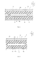
- FIG. 2 is a schematic cross-sectional view from line II-II in FIG. 1 .
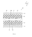
- FIG. 3 is a schematic cross-sectional view from line III-III in FIG. 1 .
- the solar module 1 includes a plurality of solar cell strings 2.
- the solar cell strings 2 are arranged at an interval from each other in one direction (the x direction). Solar strings 2 adjacent to each other in the x direction are connected to each other electrically.
- Each solar cell string 2 has a plurality of solar cells 10.
- the solar cells 10 are connected electrically by a wiring member 11. More specifically, the solar cells 10 are connected electrically in series by electrically connecting one electrode to another in adjacent solar cells 10 using a wiring member 11.
- the solar cells 10 are arranged at an interval from each other in another direction (the y direction) perpendicular to the one direction (x direction).
- the solar cells 10 in the solar module 1 are arranged at intervals in a matrix in both the x direction and the y direction.
- the wiring member 11 can be constituted from a metal such as Cu, Al or Ag, or an alloy such as a Cu alloy, Al alloy or Ag alloy.
- the wiring member 11 may also be a multilayer of a plurality of conductive members.
- the wiring member 11 and solar cells 10 are bonded using a resin adhesive 15.
- the resin adhesive 15 may comprise a resin that does not contain conductive particles. In this case, the wiring member 11 must come into direct contact with the electrodes of the solar cells 10.
- the resin adhesive 15 may also contain conductive particles dispersed throughout the resin. In this case, the wiring member 11 and the electrodes of the solar cells 10 may come into direct contact, or may come into contact via the conductive particles.
- the conductive particles can be particles of a metal such as Ag, Al, Ni, Au or Cu, or particles of an alloy comprising at least one of these metals. They can also be insulating particles covered with a conductive coating.
- the insulating particles can be ceramic particles of silica or alumina, or resin particles.
- the conductive coating can be a metal such as Ag or Al, or an alloy containing at least one of these metals.
- the resin may be a resin composition to which an additive such as a filler has been added.
- Each solar cell 10 has a light-receiving surface 10a and a back surface 10b (see FIG. 2 and FIG. 3 ).
- the main surface on which light is directly incident is the light-receiving surface 10a
- the other main surface is the back surface 10b.
- each solar cell 10 may receive light and generate electricity on both the light-receiving surface 10a and the back surface 10b.
- the solar cells 10 may generate no electricity when light is received on the back surface 10b, or may be bifacial light-receiving solar cells.
- the solar cells 10 can be crystalline silicon solar cells, thin-film silicon solar cells, compound semiconductor solar cells, organic thin-film solar cells, dye-sensitized solar cells, or quantum dot solar cells.
- a light-receiving surface protecting member 12 is arranged on the light-receiving surface 10a (z1 side) of the solar cells 10.
- the light-receiving surface protecting member 12 transmits light in the wavelengths contributing to the generation of electricity in the solar cells 10.
- the light-receiving surface protecting member 12 can be a glass plate or a plastic plate.
- a back surface protecting member 13 is arranged on the back surface 10b (z2 side) of the solar cells 10. It is a member which reflects light in the wavelengths contributing to the generation of electricity in the solar cells 10.
- the back surface protecting member 13 often has a reflective surface on the solar cell 10 side that reflects light in the wavelengths contributing to the generation of electricity in the solar cells 10. In the case of bifacial light-receiving solar cells, the back surface protecting member 13 transmits light in the wavelengths contributing to the generation of electricity in the solar cells 10.
- the back surface protecting member 13 consists of a flexible sheet.
- the back surface protecting member 13, for example, can be constituted as a member in which a weather-resistant film and a reflective layer are stacked in order from the side opposite that of the solar cell 10.
- the back surface protecting member 13 can also be constituted, for example, as a member in which a weather-resistant film and a reflective layer are stacked in order from the side opposite that of the solar cell 10.
- the reflective layer can be made of metal, an alloy or a white resin.
- An adhesive layer may be provided between the weather-resistant film and the reflective layer, and between the reflective layer and the weather-resistant film.
- the weather-resistant film, reflective layer and weather-resistant film may have a single-layer structure or a stacked structure.
- a sealing member 14 is provided between the light-receiving surface protecting member 12 and the back surface protecting member 13.
- the sealing member 14 transmits light in the wavelengths contributing to the generation of electricity in the solar cells 10.
- a plurality of solar cell strings 2 are arranged inside the sealing member 14.
- the light-receiving surface protecting member 12 is provided on the z1 side of the sealing member 14 (the side with the light-receiving surface 10a) and the back surface protecting member 13 is provided on the z2 side (the side with the back surface 10b) in the z direction, or thickness direction, of the solar cells 10.
- the entire sealing member 14 comprises resin portions containing a non-crosslinked resin.
- non-crosslinked resins that can be used as a constituent material in the sealing member 14 include olefin resins such as polyethylene (PE) and polypropylene (PP), and ionomer resins.
- Polyolefin resins are preferably used as a constituent material in the sealing member 14.
- the sealing member 14 is made of a polyolefin resin
- the polyolefin resin can effectively suppress infiltration of moisture into the sealing member 14, since polyolefin resins have a lower moisture content than ethylene-vinylacetate copolymers (EVA).
- EVA ethylene-vinylacetate copolymers
- polyolefin resins provide better electrical insulation than EVA.
- the glass transition temperature (Tg) of the resin adhesive 15 is higher than the melting point of the sealing member 14 containing a non-crosslinked resin.
- the glass transition temperature of the resin adhesive 15 is higher than the melting point of the sealing member 14 preferably by at least 10°C, and more preferably by at least 20°C. More specifically, the melting point of the sealing member 14 is preferably from 60°C to 180°C and more preferably from 60°C to 120°C.
- the glass transition temperature of the resin adhesive 15 is preferably equal to or greater than 140°C, and more preferably equal to or greater than 150°C. It is preferable to include at least one resin from among epoxy, phenol, acrylic, imide and urethane resins as a resin suitable for obtaining a resin adhesive 15 having such a glass transition temperature.
- the glass transition temperature of the resin is measured using thermo mechanical analysis (TMA).
- TMA thermo mechanical analysis
- the TMA method is used under the following conditions. Measurement Mode: Tension Weight: 1 g Temperature Gradient: 5°C/min. Sample Shape: Film
- the glass transition temperature of the resin adhesive is lower than the melting point of the sealing member, and the temperature of the sealing member exceeds the melting point of the sealing member, the resin adhesive becomes vitreous, the creep rupture phenomenon occurs, and the bonding strength of the resin adhesive deteriorates.
- stress on the wiring member and solar cells and stress from thermal expansion of the sealing member causes the wiring member to become displaced.
- the glass transition temperature of the resin adhesive 15 is lower than the melting point of the sealing member 14. Therefore, when the solar module 1 is heated and the temperature of the sealing member 14 exceeds the melting point of the sealing member 14, the resin adhesive 15 becomes vitreous but the creep rupture phenomenon does not occur. As a result, displacement of the wiring member 11 can be more effectively controlled, and a more reliable solar module is obtained. Lowering the melting point of the sealing member 14 without altering the melting point of the resin adhesive 15 can be thought of as a way to raise the glass transition temperature of the resin adhesive 15 above the melting point of the sealing member 14. However, if the melting point of the sealing member 14 is too low, the viscosity of the sealing member 14 may be too low when the temperature of the solar module 1 rises.
- the melting point of the sealing member 14 is preferably from 60°C to 180°C, and more preferably from 60°C to 120°C.
- a light-receiving surface protecting member 12 a first resin sheet 21 for constituting a portion of the sealing member 14, a solar cell string 2, a second resin sheet 22, and a back surface protecting member 13 are stacked in this order.
- the entire sealing member 14 comprises resin portions containing a non-crosslinked resin.
- both the first and second resin sheets 21 and 22 contain a non-crosslinked resin.
- multilayers 23 are laminated to create a sealing member 14 from first and second resin sheets 21 and 22 (lamination process). This completes the solar module 1.
- the multilayers 23 are laminated at a temperature lower than the glass transition temperature of the resin adhesive 15. For this reason, during the lamination process, the resin adhesive 15 becomes vitreous but the creep fracture phenomenon does not occur and the adhesiveness of the resin adhesive 15 is maintained. Therefore, displacement of the wiring member 11 during the lamination process can be controlled. As a result, the positional accuracy of the wiring member 11 is high, and highly reliable solar modules 1 can be obtained using a high-yield solar module manufacturing method.
- the multilayers 23 are laminated at a temperature lower than the glass transition temperature of the resin adhesive 15, preferably by at least 10°C and more preferably by at least 20°C.
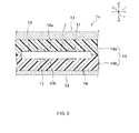
- FIG. 5 is a schematic cross-sectional view along the x-direction and the z-direction of a solar module 1a according to a second embodiment.
- the first embodiment contained an explanation of an example in which the entire sealing member 14 comprises resin portions containing a non-crosslinked resin.
- the sealing member 14 includes a first sealing member portion 14a which comes into contact with the light-receiving surface 10a of a solar cell 10, and a second sealing member portion 14b which comes into contact with the back surface 10b of the solar cell 10.
- the second sealing member 14b contains a non-crosslinked resin, but the first sealing member 14a contains a crosslinked resin such as ethylene-vinylacetate (EVA) containing a crosslinking agent.
- EVA ethylene-vinylacetate
- the glass transition temperature of the resin adhesive 15 is higher than the melting point of the second sealing member 14b. For this reason, if the temperature of the solar module 1a rises, the second sealing member 14b melts, and the wiring member 11 is subjected to stress due to the thermal expansion coefficient. Even so, positional displacement of the wiring member 11 can be controlled in the portion bonded to the back surface 10b.
- Displacement of the portion of the wiring member on the side with light-receiving surface protecting member is unlikely to occur because thermal expansion of the sealing member portion is restricted by the light-receiving surface protecting member, which comprises a rigid substrate. Displacement of the portion of the wiring member on the side with the back surface protecting member is more likely to occur because thermal expansion of the sealing member portion is not effectively restricted by the back surface protecting member, which comprises a flexible sheet. Therefore, when only one of the first and second sealing material portions includes a non-crosslinked resin, as in the present embodiment, the one containing the crosslinked resin is preferably the second sealing member portion positioned on the side with the back surface protecting member, which comprises a flexible sheet.
- the solar module 1a can be manufactured using substantially the same method as explained in the first embodiment. The only difference is that the first resin sheet 21 is a resin sheet containing a crosslinked resin, and the second resin sheet 22 is a resin sheet containing a non-crosslinked resin.
- the temperature at which the multilayers 23 are laminated is lower than the glass transition temperature of the resin adhesive 15, preferably lower than the glass transition temperature of the resin adhesive 15 by at least 10°C. In this way, positional displacement of the wiring member 11 can be controlled in the portion bonded to the back surface 10b.
- the sealing member there are no particular restrictions on the sealing member as long as the portion in contact with the wiring member on at least one main surface of the solar cells contains a non-crosslinked resin.
- the present invention includes many embodiments not described herein.
- the entire sealing member may contain a non-crosslinked resin.
- the sealing member may also consist of three or more sealing member portions.
- polyethylene (PE) with a melting point of 120°C was used as the non-crosslinked sealing member 14 in the creation of solar modules having a configuration substantially identical to that of the solar module 1 according to the embodiment described above.
- the glass transition temperature of the resin adhesive 15 was in a range from 120°C to 150°C.
- Table 1 shows the sealing members 14 used in the test examples and their melting points, the temperatures of the sealing members 14 during lamination, the glass transition temperatures of the resin adhesives 15, the incidence of displacement of the wiring member 11 from the solar cell 10 after lamination, and the incidence of displacement of the wiring member 11 from the solar cell 10 outdoors.
- the incidence of displacement of wiring members 11 from solar cells 10 after lamination in Table 1 was calculated by counting the number of solar modules, out of a total of 50 solar modules, in which a wiring member 11 became displaced from a solar cell 10 by a predetermined amount after lamination.
- the lamination was performed at a thermo-compression bonding temperature of 150°C, and at an evacuation time and bonding time of ten minutes each. During the evacuation time and bonding time, air bubbles are eliminated from the solar module 1 after lamination. As a result, the temperature of the sealing member 14 was 130°C in the test examples.
- a 50 mm 2 heater was placed in the central portion of the back surface protecting member 13 to heat the sealing member 14 in contact with the back surface protecting member 13 to a temperature of 140°C. After being held at this temperature for 30 minutes, the portion was cooled to room temperature (25°C) to complete a single cycle. After ten of these cycles, the incidence of displacement of wiring members 11 from solar cells 10 was determined.
- a glass transition temperature 15 of 150°C or greater has been found to be especially preferred for the resin adhesive 15 used to connect solar cells 10 and wiring members 11.
Landscapes
- Chemical & Material Sciences (AREA)
- Organic Chemistry (AREA)
- Photovoltaic Devices (AREA)
- Electroluminescent Light Sources (AREA)
- Adhesives Or Adhesive Processes (AREA)
Abstract
Description
- The present invention relates to a solar module and to a manufacturing method therefor.
- Solar modules have attracted much attention in recent years as an energy source with a low environmental impact. The solar module in Patent Document 1 includes a plurality of solar cells arranged inside a sealing member. The solar cells are connected electrically by a wiring member. The wiring member is connected to the solar cells using a resin adhesive.
- Patent Document 1: Laid-Open Patent Publication No.
2010-225801 - Because a solar module is installed in a location exposed to sunlight, the temperature of the solar module is often high and the solar module is subjected to thermal stress. A solar module is also subjected to thermal stress during the lamination process in which the solar cells are modularized. Therefore, a solar module which is more reliable with respect to thermal stress is desired.
- In view of this situation, it is an object of the present invention to provide a highly reliable solar module.
- The solar module of the present invention includes a sealing member, a plurality of solar cells, a wiring member, and a resin adhesive. The solar cells are arranged in the sealing member. The wiring member connects the solar cells electrically. The resin adhesive bonds the wiring member and the solar cells. A portion of the sealing member in contact with at least one main surface of the solar cells contains a non-crosslinked resin. The glass transition temperature of the resin adhesive is higher than the melting point of the resin portion of the sealing member containing the non-crosslinked resin.
- The present invention relates to a manufacturing method for a solar module having a sealing member and a solar cell string arranged inside the sealing member, the solar cell string having a plurality of solar cells, a wiring member connecting the plurality of solar cells electrically, and a resin adhesive bonding the wiring member and the plurality of solar cells. In the manufacturing method for a solar module of the present invention, a first resin sheet for constituting a portion of the sealing member, the solar cell string, and a second resin sheet for constituting another portion of the sealing member are stacked in this order to create multilayers. By laminating multilayers, the sealing member is configured from the first and second resin sheets and a solar module is obtained. The lamination of the multilayers is performed at a temperature equal to or less than the glass transition temperature of the resin adhesive.
- The present invention is able to provide a highly reliable solar module.
-
-
FIG. 1 is a schematic plan view of a solar module according to a first embodiment. -
FIG. 2 is a schematic cross-sectional view from line II-II inFIG. 1 . -
FIG. 3 is a schematic cross-sectional view from line III-III inFIG. 1 . -
FIG. 4 is a schematic cross-sectional view used to explain the manufacturing process for a solar module according to the first embodiment. -
FIG. 5 is a schematic cross-sectional view along the x-direction and the z-direction of a solar module according to a second embodiment. - The following is an explanation of examples of preferred embodiments of the present invention. The following embodiments are merely examples. The present invention is not limited to the following embodiments in any way.
- Further, in each of the drawings referenced in the embodiments, members having substantially the same function are denoted by the same symbols. The drawings referenced in the embodiments are also depicted schematically. The dimensional ratios of the objects depicted in the drawings may differ from those of the actual objects. The dimensional ratios of objects may also vary between drawings. The specific dimensional ratios of the objects should be determined with reference to the following explanation.
-
FIG. 1 is a schematic plan view of a solar module according to a first embodiment.FIG. 2 is a schematic cross-sectional view from line II-II inFIG. 1 .FIG. 3 is a schematic cross-sectional view from line III-III inFIG. 1 . - The solar module 1 includes a plurality of solar cell strings 2. The
solar cell strings 2 are arranged at an interval from each other in one direction (the x direction).Solar strings 2 adjacent to each other in the x direction are connected to each other electrically. - Each
solar cell string 2 has a plurality ofsolar cells 10. In eachsolar cell string 2, thesolar cells 10 are connected electrically by awiring member 11. More specifically, thesolar cells 10 are connected electrically in series by electrically connecting one electrode to another in adjacentsolar cells 10 using awiring member 11. In eachsolar cell string 2, thesolar cells 10 are arranged at an interval from each other in another direction (the y direction) perpendicular to the one direction (x direction). Thus, thesolar cells 10 in the solar module 1 are arranged at intervals in a matrix in both the x direction and the y direction. - The
wiring member 11 can be constituted from a metal such as Cu, Al or Ag, or an alloy such as a Cu alloy, Al alloy or Ag alloy. Thewiring member 11 may also be a multilayer of a plurality of conductive members. - The
wiring member 11 andsolar cells 10 are bonded using aresin adhesive 15. Theresin adhesive 15 may comprise a resin that does not contain conductive particles. In this case, thewiring member 11 must come into direct contact with the electrodes of thesolar cells 10. Theresin adhesive 15 may also contain conductive particles dispersed throughout the resin. In this case, thewiring member 11 and the electrodes of thesolar cells 10 may come into direct contact, or may come into contact via the conductive particles. - The conductive particles can be particles of a metal such as Ag, Al, Ni, Au or Cu, or particles of an alloy comprising at least one of these metals. They can also be insulating particles covered with a conductive coating. The insulating particles can be ceramic particles of silica or alumina, or resin particles. The conductive coating can be a metal such as Ag or Al, or an alloy containing at least one of these metals.
- In the present invention, the resin may be a resin composition to which an additive such as a filler has been added.
- Each
solar cell 10 has a light-receivingsurface 10a and aback surface 10b (seeFIG. 2 and FIG. 3 ). Here, the main surface on which light is directly incident is the light-receivingsurface 10a, and the other main surface is theback surface 10b. However, eachsolar cell 10 may receive light and generate electricity on both the light-receivingsurface 10a and theback surface 10b. In other words, thesolar cells 10 may generate no electricity when light is received on theback surface 10b, or may be bifacial light-receiving solar cells. - There are no particular restrictions on the type of
solar cells 10. Thesolar cells 10 can be crystalline silicon solar cells, thin-film silicon solar cells, compound semiconductor solar cells, organic thin-film solar cells, dye-sensitized solar cells, or quantum dot solar cells. - A light-receiving
surface protecting member 12 is arranged on the light-receivingsurface 10a (z1 side) of thesolar cells 10. The light-receivingsurface protecting member 12 transmits light in the wavelengths contributing to the generation of electricity in thesolar cells 10. The light-receivingsurface protecting member 12 can be a glass plate or a plastic plate. - A back
surface protecting member 13 is arranged on theback surface 10b (z2 side) of thesolar cells 10. It is a member which reflects light in the wavelengths contributing to the generation of electricity in thesolar cells 10. The backsurface protecting member 13 often has a reflective surface on thesolar cell 10 side that reflects light in the wavelengths contributing to the generation of electricity in thesolar cells 10. In the case of bifacial light-receiving solar cells, the backsurface protecting member 13 transmits light in the wavelengths contributing to the generation of electricity in thesolar cells 10. - The back
surface protecting member 13 consists of a flexible sheet. The backsurface protecting member 13, for example, can be constituted as a member in which a weather-resistant film and a reflective layer are stacked in order from the side opposite that of thesolar cell 10. The backsurface protecting member 13 can also be constituted, for example, as a member in which a weather-resistant film and a reflective layer are stacked in order from the side opposite that of thesolar cell 10. The reflective layer can be made of metal, an alloy or a white resin. An adhesive layer may be provided between the weather-resistant film and the reflective layer, and between the reflective layer and the weather-resistant film. The weather-resistant film, reflective layer and weather-resistant film may have a single-layer structure or a stacked structure. - A sealing
member 14 is provided between the light-receivingsurface protecting member 12 and the backsurface protecting member 13. The sealingmember 14 transmits light in the wavelengths contributing to the generation of electricity in thesolar cells 10. A plurality ofsolar cell strings 2 are arranged inside the sealingmember 14. The light-receivingsurface protecting member 12 is provided on the z1 side of the sealing member 14 (the side with the light-receivingsurface 10a) and the backsurface protecting member 13 is provided on the z2 side (the side with theback surface 10b) in the z direction, or thickness direction, of thesolar cells 10. - In the present embodiment, the entire sealing
member 14 comprises resin portions containing a non-crosslinked resin. Preferred examples of non-crosslinked resins that can be used as a constituent material in the sealingmember 14 include olefin resins such as polyethylene (PE) and polypropylene (PP), and ionomer resins. - Polyolefin resins are preferably used as a constituent material in the sealing
member 14. When the sealingmember 14 is made of a polyolefin resin, the polyolefin resin can effectively suppress infiltration of moisture into the sealingmember 14, since polyolefin resins have a lower moisture content than ethylene-vinylacetate copolymers (EVA). Also, polyolefin resins provide better electrical insulation than EVA. By configuring the sealingmember 14 from a polyolefin resin, the reliability of the solar module 1 can be further increased. - In the solar module 1, the glass transition temperature (Tg) of the
resin adhesive 15 is higher than the melting point of the sealingmember 14 containing a non-crosslinked resin. The glass transition temperature of theresin adhesive 15 is higher than the melting point of the sealingmember 14 preferably by at least 10°C, and more preferably by at least 20°C. More specifically, the melting point of the sealingmember 14 is preferably from 60°C to 180°C and more preferably from 60°C to 120°C. The glass transition temperature of theresin adhesive 15 is preferably equal to or greater than 140°C, and more preferably equal to or greater than 150°C. It is preferable to include at least one resin from among epoxy, phenol, acrylic, imide and urethane resins as a resin suitable for obtaining aresin adhesive 15 having such a glass transition temperature. - In the present invention, the glass transition temperature of the resin is measured using thermo mechanical analysis (TMA). The TMA method is used under the following conditions.
Measurement Mode: Tension
Weight: 1 g
Temperature Gradient: 5°C/min.
Sample Shape: Film - Exposure to sunlight often causes the temperature of a solar module to rise and the temperature of the sealing member to exceed the melting point of the sealing member. When the glass transition temperature of the resin adhesive is lower than the melting point of the sealing member, and the temperature of the sealing member exceeds the melting point of the sealing member, the resin adhesive becomes vitreous, the creep rupture phenomenon occurs, and the bonding strength of the resin adhesive deteriorates. As a result, stress on the wiring member and solar cells and stress from thermal expansion of the sealing member causes the wiring member to become displaced.
- In the present embodiment, however, the glass transition temperature of the
resin adhesive 15 is lower than the melting point of the sealingmember 14. Therefore, when the solar module 1 is heated and the temperature of the sealingmember 14 exceeds the melting point of the sealingmember 14, theresin adhesive 15 becomes vitreous but the creep rupture phenomenon does not occur. As a result, displacement of thewiring member 11 can be more effectively controlled, and a more reliable solar module is obtained.
Lowering the melting point of the sealingmember 14 without altering the melting point of theresin adhesive 15 can be thought of as a way to raise the glass transition temperature of theresin adhesive 15 above the melting point of the sealingmember 14. However, if the melting point of the sealingmember 14 is too low, the viscosity of the sealingmember 14 may be too low when the temperature of the solar module 1 rises. However, when the melting point of the sealingmember 14 becomes too high while the melting point of theresin adhesive 15 remains unaltered, the time required to perform the lamination process and manufacture a solar module increases. Therefore, the melting point of the sealingmember 14 is preferably from 60°C to 180°C, and more preferably from 60°C to 120°C. - The following is an explanation of an example of a manufacturing method for a solar module 1 with reference primarily to
FIG. 4 . - First, a light-receiving
surface protecting member 12, afirst resin sheet 21 for constituting a portion of the sealingmember 14, asolar cell string 2, asecond resin sheet 22, and a backsurface protecting member 13 are stacked in this order. This creates amultilayer 23. In the solar module 1, the entire sealingmember 14 comprises resin portions containing a non-crosslinked resin. For this reason, both the first andsecond resin sheets - Next,
multilayers 23 are laminated to create a sealingmember 14 from first andsecond resin sheets 21 and 22 (lamination process). This completes the solar module 1. - In the present embodiment, the
multilayers 23 are laminated at a temperature lower than the glass transition temperature of theresin adhesive 15. For this reason, during the lamination process, theresin adhesive 15 becomes vitreous but the creep fracture phenomenon does not occur and the adhesiveness of theresin adhesive 15 is maintained. Therefore, displacement of thewiring member 11 during the lamination process can be controlled. As a result, the positional accuracy of thewiring member 11 is high, and highly reliable solar modules 1 can be obtained using a high-yield solar module manufacturing method. - In order to more effectively control the displacement of the
wiring member 11 during the lamination process, themultilayers 23 are laminated at a temperature lower than the glass transition temperature of theresin adhesive 15, preferably by at least 10°C and more preferably by at least 20°C. - The following is an explanation of another example of a preferred embodiment of the present invention. In the following explanation, all members having functions substantially identical to those in the first embodiment are denoted by the same reference symbols and further explanation of these members has been omitted.
-
FIG. 5 is a schematic cross-sectional view along the x-direction and the z-direction of asolar module 1a according to a second embodiment. - The first embodiment contained an explanation of an example in which the entire sealing
member 14 comprises resin portions containing a non-crosslinked resin. - In the
solar module 1a, the sealingmember 14 includes a firstsealing member portion 14a which comes into contact with the light-receivingsurface 10a of asolar cell 10, and a secondsealing member portion 14b which comes into contact with theback surface 10b of thesolar cell 10. Thesecond sealing member 14b contains a non-crosslinked resin, but thefirst sealing member 14a contains a crosslinked resin such as ethylene-vinylacetate (EVA) containing a crosslinking agent. - In the
solar module 1a, the glass transition temperature of theresin adhesive 15 is higher than the melting point of thesecond sealing member 14b. For this reason, if the temperature of thesolar module 1a rises, thesecond sealing member 14b melts, and thewiring member 11 is subjected to stress due to the thermal expansion coefficient. Even so, positional displacement of thewiring member 11 can be controlled in the portion bonded to theback surface 10b. - Displacement of the portion of the wiring member on the side with light-receiving surface protecting member is unlikely to occur because thermal expansion of the sealing member portion is restricted by the light-receiving surface protecting member, which comprises a rigid substrate. Displacement of the portion of the wiring member on the side with the back surface protecting member is more likely to occur because thermal expansion of the sealing member portion is not effectively restricted by the back surface protecting member, which comprises a flexible sheet. Therefore, when only one of the first and second sealing material portions includes a non-crosslinked resin, as in the present embodiment, the one containing the crosslinked resin is preferably the second sealing member portion positioned on the side with the back surface protecting member, which comprises a flexible sheet.
- The
solar module 1a can be manufactured using substantially the same method as explained in the first embodiment. The only difference is that thefirst resin sheet 21 is a resin sheet containing a crosslinked resin, and thesecond resin sheet 22 is a resin sheet containing a non-crosslinked resin. During the manufacture ofsolar module 1a, as in the case of the manufacture of solar module 1, the temperature at which themultilayers 23 are laminated is lower than the glass transition temperature of theresin adhesive 15, preferably lower than the glass transition temperature of theresin adhesive 15 by at least 10°C. In this way, positional displacement of thewiring member 11 can be controlled in the portion bonded to theback surface 10b. - In the present invention, there are no particular restrictions on the sealing member as long as the portion in contact with the wiring member on at least one main surface of the solar cells contains a non-crosslinked resin.
- The present invention includes many embodiments not described herein. In the manufacturing method for a solar module according to the present invention, the entire sealing member may contain a non-crosslinked resin.
- The sealing member may also consist of three or more sealing member portions.
- The present invention will now be explained in greater detail with reference to specific test examples. The present invention is not limited to the following test examples in any way. Modifications are possible without altering the spirit of the present invention.
- In the test examples, polyethylene (PE) with a melting point of 120°C was used as the non-crosslinked sealing
member 14 in the creation of solar modules having a configuration substantially identical to that of the solar module 1 according to the embodiment described above. As shown in Table 1, the glass transition temperature of the resin adhesive 15 (as measured using the TMA method) was in a range from 120°C to 150°C. - Table 1 shows the sealing
members 14 used in the test examples and their melting points, the temperatures of the sealingmembers 14 during lamination, the glass transition temperatures of theresin adhesives 15, the incidence of displacement of thewiring member 11 from thesolar cell 10 after lamination, and the incidence of displacement of thewiring member 11 from thesolar cell 10 outdoors.Table 1 Sealing Member 14/ Melting PointTemperature of Sealing Member 14 During LaminationGlass Transition Temperature of Resin Adhesive 15Incidence of displacement of wiring member 11 fromsolar cell 10 after laminationIncidence of displacement of wiring member 11 fromsolar cell 10 outdoorsPE/120°C 130°C 120°C 20% 30% PE/120°C 130°C 130°C 5% 20% PE/120°C 130°C 140°C 0% 5% PE/120°C 130°C 150°C 0% 0% - The incidence of displacement of
wiring members 11 fromsolar cells 10 after lamination in Table 1 was calculated by counting the number of solar modules, out of a total of 50 solar modules, in which awiring member 11 became displaced from asolar cell 10 by a predetermined amount after lamination. - In the test examples, the lamination was performed at a thermo-compression bonding temperature of 150°C, and at an evacuation time and bonding time of ten minutes each. During the evacuation time and bonding time, air bubbles are eliminated from the solar module 1 after lamination. As a result, the temperature of the sealing
member 14 was 130°C in the test examples. - The incidence of displacement of
wiring members 11 fromsolar cells 10 was determined in indoor testing described below. - A 50 mm2 heater was placed in the central portion of the back
surface protecting member 13 to heat the sealingmember 14 in contact with the backsurface protecting member 13 to a temperature of 140°C. After being held at this temperature for 30 minutes, the portion was cooled to room temperature (25°C) to complete a single cycle. After ten of these cycles, the incidence of displacement ofwiring members 11 fromsolar cells 10 was determined. - It was clear from the results of the test examples that displacement of
wiring members 11 during the lamination process could be controlled by performing lamination when the glass transition temperature of the sealing member (lamination temperature) is at or below the glass transition temperature of theresin adhesive 15. - It was also found that a resin adhesive 15 with a glass transition temperature greater than the melting point of the sealing
member 14 could more effectively control displacement of wiring members and produce a highly reliable solar module even when the temperature of the sealingmember 14 was above the melting point of the sealingmember 14. - A
glass transition temperature 15 of 150°C or greater has been found to be especially preferred for theresin adhesive 15 used to connectsolar cells 10 andwiring members 11. -
- 1, 1a: Solar module
- 2: Solar cell string
- 10: Solar cell
- 10a: Light-receiving surface
- 10b: Back surface
- 11: Wiring member
- 12: Light-receiving surface protecting member
- 13: Back surface protecting member
- 14: Sealing member
- 14a: First sealing member portion
- 14b: Second sealing member portion
- 15: Resin adhesive
- 21: First resin sheet
- 22: Second resin sheet
- 23: Multilayer
Claims (7)
- A solar module comprising:a sealing member;a plurality of solar cells arranged inside the sealing member;a wiring member connecting the plurality of solar cells electrically; anda resin adhesive bonding the wiring member and the plurality of solar cells;a portion of the sealing member, in contact with at least one main surface of the solar cells, containing a non-crosslinked resin, andthe glass transition temperature of the resin adhesive being higher than the melting point of the resin portion of the sealing member containing the non-crosslinked resin.
- The solar module according to claim 1, wherein the resin adhesive includes at least one resin selected from a group comprising epoxy, acrylic, phenol, and imide; and
the resin portion including at least one non-crosslinked resin selected from a group comprising polyolefin resins, ionomer resins, acrylic resins, polystyrene resins, urethane resins, and elastomeric resins. - The solar module according to claim 1 or claim 2, wherein the glass transition temperature of the resin adhesive is greater than the melting point of the resin portion by at least 10°C.
- The solar module according to any one of claims 1 through 3, wherein the glass transition temperature of the resin adhesive is equal to or greater than 140°C.
- A manufacturing method for a solar module having a sealing member and a solar cell string arranged inside the sealing member, the solar cell string having a plurality of solar cells, a wiring member connecting the plurality of solar cells electrically, and a resin adhesive bonding the wiring member and the plurality of solar cells, the manufacturing method comprising the steps of:stacking a first resin sheet for constituting a portion of the sealing member, the solar cell string, and a second resin sheet for constituting another portion of the sealing member in this order to create multilayers; andlaminating the multilayers to configure the sealing member from the first and second resin sheets and obtain a solar module;the lamination of the multilayers being performed at a temperature equal to or less than the glass transition temperature of the resin adhesive.
- The manufacturing method for a solar module according to claim 5, wherein at least one of the first and second resin sheets contains a non-crosslinked resin.
- The manufacturing method for a solar module according to claim 5 or claim 6, wherein the lamination of the multilayer is performed at a temperature lower than the glass transition temperature of the resin adhesive by at least 10°C.
Applications Claiming Priority (2)
| Application Number | Priority Date | Filing Date | Title |
|---|---|---|---|
| JP2011118759A JP5838321B2 (en) | 2011-05-27 | 2011-05-27 | Manufacturing method of solar cell module |
| PCT/JP2012/056892 WO2012165003A1 (en) | 2011-05-27 | 2012-03-16 | Solar cell module and manufacturing method thereof |
Publications (3)
| Publication Number | Publication Date |
|---|---|
| EP2717328A1 true EP2717328A1 (en) | 2014-04-09 |
| EP2717328A4 EP2717328A4 (en) | 2015-06-10 |
| EP2717328B1 EP2717328B1 (en) | 2020-10-07 |
Family
ID=47258869
Family Applications (1)
| Application Number | Title | Priority Date | Filing Date |
|---|---|---|---|
| EP12791968.6A Not-in-force EP2717328B1 (en) | 2011-05-27 | 2012-03-16 | Manufacturing method for a solar modul |
Country Status (5)
| Country | Link |
|---|---|
| US (1) | US20140069487A1 (en) |
| EP (1) | EP2717328B1 (en) |
| JP (1) | JP5838321B2 (en) |
| CN (1) | CN103597610B (en) |
| WO (1) | WO2012165003A1 (en) |
Families Citing this family (3)
| Publication number | Priority date | Publication date | Assignee | Title |
|---|---|---|---|---|
| CN106206808B (en) * | 2014-10-31 | 2018-06-26 | 比亚迪股份有限公司 | Solar cell module and preparation method thereof |
| TW201909435A (en) * | 2017-07-20 | 2019-03-01 | 財團法人工業技術研究院 | Solar photovoltaic module |
| JP2021034659A (en) * | 2019-08-28 | 2021-03-01 | パナソニック株式会社 | Solar cell module |
Family Cites Families (15)
| Publication number | Priority date | Publication date | Assignee | Title |
|---|---|---|---|---|
| JPH06334207A (en) * | 1993-05-27 | 1994-12-02 | Canon Inc | Solar cell module |
| US20010008169A1 (en) * | 1998-06-30 | 2001-07-19 | 3M Innovative Properties Company | Fine pitch anisotropic conductive adhesive |
| EP1059675B1 (en) * | 1999-06-08 | 2009-05-20 | Kaneka Corporation | Method of encapsulating a photovoltaic module by an encapsulating material |
| JP2000349313A (en) * | 1999-06-08 | 2000-12-15 | Kanegafuchi Chem Ind Co Ltd | Sealing member for solar cell module and sealing method |
| EP1560272B1 (en) * | 2004-01-29 | 2016-04-27 | Panasonic Intellectual Property Management Co., Ltd. | Solar cell module |
| JP5288790B2 (en) * | 2007-08-02 | 2013-09-11 | 三洋電機株式会社 | Solar cell module and manufacturing method thereof |
| EP2020688B1 (en) * | 2007-08-02 | 2013-11-27 | Sanyo Electric Co., Ltd. | Solar cell interconnection using thermo-compression bonding and correspondingly fabricated module |
| JP5484663B2 (en) * | 2007-09-25 | 2014-05-07 | 三洋電機株式会社 | Manufacturing method of solar cell module |
| JP5126233B2 (en) * | 2007-10-05 | 2013-01-23 | 日立化成工業株式会社 | Adhesive composition, circuit connection material using the same, circuit member connection method, circuit connection body, and cured product of adhesive composition |
| EP2249398A1 (en) * | 2008-02-28 | 2010-11-10 | SANYO Electric Co., Ltd. | Solar cell module |
| JP2010024416A (en) * | 2008-07-24 | 2010-02-04 | Sumitomo Electric Ind Ltd | Adhesive for connecting electrodes |
| US20100065105A1 (en) * | 2008-09-12 | 2010-03-18 | Francois Andre Koran | Thin Film Photovoltaic Module Having a Contoured Substrate |
| JP5436901B2 (en) | 2009-03-23 | 2014-03-05 | 三洋電機株式会社 | Manufacturing method of solar cell module |
| JP5506295B2 (en) * | 2009-08-28 | 2014-05-28 | 京セラ株式会社 | Solar cell module and manufacturing method thereof |
| JP2011054663A (en) * | 2009-08-31 | 2011-03-17 | Sanyo Electric Co Ltd | Solar cell module |
-
2011
- 2011-05-27 JP JP2011118759A patent/JP5838321B2/en active Active
-
2012
- 2012-03-16 EP EP12791968.6A patent/EP2717328B1/en not_active Not-in-force
- 2012-03-16 WO PCT/JP2012/056892 patent/WO2012165003A1/en not_active Ceased
- 2012-03-16 CN CN201280027127.1A patent/CN103597610B/en active Active
-
2013
- 2013-11-18 US US14/082,602 patent/US20140069487A1/en not_active Abandoned
Also Published As
| Publication number | Publication date |
|---|---|
| EP2717328A4 (en) | 2015-06-10 |
| JP5838321B2 (en) | 2016-01-06 |
| US20140069487A1 (en) | 2014-03-13 |
| JP2012248654A (en) | 2012-12-13 |
| CN103597610B (en) | 2016-01-20 |
| WO2012165003A1 (en) | 2012-12-06 |
| CN103597610A (en) | 2014-02-19 |
| EP2717328B1 (en) | 2020-10-07 |
Similar Documents
| Publication | Publication Date | Title |
|---|---|---|
| KR101215694B1 (en) | Solar Cell Module And Manufacturing Method Thereof | |
| CN102971865B (en) | Solar module and manufacture method thereof | |
| TWI624072B (en) | Solar battery module manufacturing method, solar battery module and wiring connection method | |
| KR101441264B1 (en) | Solar cell module, method for producing solar cell module, solar cell, and method for connecting tab wire | |
| CN113037210A (en) | Battery string structure, photovoltaic module and manufacturing method of photovoltaic module | |
| KR102408270B1 (en) | Solar module with aligning encapsulant | |
| CN103730529B (en) | Photovoltaic module back-contact back-sheet and manufacture method thereof including solaode | |
| JP7509249B2 (en) | Current collector wire fixing film for solar cell module, and solar cell module using same | |
| JP2011151334A (en) | Method of manufacturing solar cell module | |
| EP3389099A1 (en) | Photovoltaic module, photovoltaic encapsulant and method of producing a photovoltaic module | |
| US20160372618A1 (en) | Solar Cell Strip Assembly and Method of Making | |
| WO2023108984A1 (en) | Photovoltaic module and preparation method therefor | |
| CN115172535A (en) | Preparation method of photovoltaic module and photovoltaic module | |
| CN114582999B (en) | Solar cell module and method for manufacturing the same | |
| EP2717328B1 (en) | Manufacturing method for a solar modul | |
| TWI590482B (en) | Solar battery module and manufacturing method thereof | |
| US20150263196A1 (en) | Photovoltaic module and process for manufacture thereof | |
| JP2012109416A (en) | Back sheet for solar cell and method for manufacturing the same | |
| JP2014013876A (en) | Solar cell module and method for manufacturing the same | |
| CN116504874A (en) | Photovoltaic module and its preparation method, stringing equipment | |
| JP2012079838A (en) | Solar cell module and method for manufacturing the same | |
| JP2011222744A (en) | Tab wire for connecting solar battery, connection method and solar battery module | |
| JP5652911B2 (en) | Manufacturing method of solar cell module | |
| KR101999591B1 (en) | Encapsulation sheet having electrode for solar cell, method for manufacturing the same, solar cell module comprising the same and method for manufacturing the same | |
| KR101283142B1 (en) | Solar apparatus and method of fabricating the same |
Legal Events
| Date | Code | Title | Description |
|---|---|---|---|
| PUAI | Public reference made under article 153(3) epc to a published international application that has entered the european phase |
Free format text: ORIGINAL CODE: 0009012 |
|
| 17P | Request for examination filed |
Effective date: 20131206 |
|
| AK | Designated contracting states |
Kind code of ref document: A1 Designated state(s): AL AT BE BG CH CY CZ DE DK EE ES FI FR GB GR HR HU IE IS IT LI LT LU LV MC MK MT NL NO PL PT RO RS SE SI SK SM TR |
|
| DAX | Request for extension of the european patent (deleted) | ||
| RA4 | Supplementary search report drawn up and despatched (corrected) |
Effective date: 20150513 |
|
| RIC1 | Information provided on ipc code assigned before grant |
Ipc: H01L 31/048 20140101AFI20150507BHEP |
|
| RAP1 | Party data changed (applicant data changed or rights of an application transferred) |
Owner name: PANASONIC INTELLECTUAL PROPERTY MANAGEMENT CO., LT |
|
| 17Q | First examination report despatched |
Effective date: 20160310 |
|
| STAA | Information on the status of an ep patent application or granted ep patent |
Free format text: STATUS: EXAMINATION IS IN PROGRESS |
|
| GRAP | Despatch of communication of intention to grant a patent |
Free format text: ORIGINAL CODE: EPIDOSNIGR1 |
|
| STAA | Information on the status of an ep patent application or granted ep patent |
Free format text: STATUS: GRANT OF PATENT IS INTENDED |
|
| INTG | Intention to grant announced |
Effective date: 20200709 |
|
| GRAS | Grant fee paid |
Free format text: ORIGINAL CODE: EPIDOSNIGR3 |
|
| GRAA | (expected) grant |
Free format text: ORIGINAL CODE: 0009210 |
|
| STAA | Information on the status of an ep patent application or granted ep patent |
Free format text: STATUS: THE PATENT HAS BEEN GRANTED |
|
| AK | Designated contracting states |
Kind code of ref document: B1 Designated state(s): AL AT BE BG CH CY CZ DE DK EE ES FI FR GB GR HR HU IE IS IT LI LT LU LV MC MK MT NL NO PL PT RO RS SE SI SK SM TR |
|
| REG | Reference to a national code |
Ref country code: GB Ref legal event code: FG4D |
|
| REG | Reference to a national code |
Ref country code: CH Ref legal event code: EP Ref country code: AT Ref legal event code: REF Ref document number: 1322081 Country of ref document: AT Kind code of ref document: T Effective date: 20201015 |
|
| REG | Reference to a national code |
Ref country code: IE Ref legal event code: FG4D |
|
| REG | Reference to a national code |
Ref country code: DE Ref legal event code: R096 Ref document number: 602012072698 Country of ref document: DE |
|
| REG | Reference to a national code |
Ref country code: NL Ref legal event code: MP Effective date: 20201007 |
|
| REG | Reference to a national code |
Ref country code: AT Ref legal event code: MK05 Ref document number: 1322081 Country of ref document: AT Kind code of ref document: T Effective date: 20201007 |
|
| PG25 | Lapsed in a contracting state [announced via postgrant information from national office to epo] |
Ref country code: FI Free format text: LAPSE BECAUSE OF FAILURE TO SUBMIT A TRANSLATION OF THE DESCRIPTION OR TO PAY THE FEE WITHIN THE PRESCRIBED TIME-LIMIT Effective date: 20201007 Ref country code: RS Free format text: LAPSE BECAUSE OF FAILURE TO SUBMIT A TRANSLATION OF THE DESCRIPTION OR TO PAY THE FEE WITHIN THE PRESCRIBED TIME-LIMIT Effective date: 20201007 Ref country code: PT Free format text: LAPSE BECAUSE OF FAILURE TO SUBMIT A TRANSLATION OF THE DESCRIPTION OR TO PAY THE FEE WITHIN THE PRESCRIBED TIME-LIMIT Effective date: 20210208 Ref country code: NL Free format text: LAPSE BECAUSE OF FAILURE TO SUBMIT A TRANSLATION OF THE DESCRIPTION OR TO PAY THE FEE WITHIN THE PRESCRIBED TIME-LIMIT Effective date: 20201007 Ref country code: NO Free format text: LAPSE BECAUSE OF FAILURE TO SUBMIT A TRANSLATION OF THE DESCRIPTION OR TO PAY THE FEE WITHIN THE PRESCRIBED TIME-LIMIT Effective date: 20210107 Ref country code: GR Free format text: LAPSE BECAUSE OF FAILURE TO SUBMIT A TRANSLATION OF THE DESCRIPTION OR TO PAY THE FEE WITHIN THE PRESCRIBED TIME-LIMIT Effective date: 20210108 |
|
| REG | Reference to a national code |
Ref country code: LT Ref legal event code: MG4D |
|
| PG25 | Lapsed in a contracting state [announced via postgrant information from national office to epo] |
Ref country code: AT Free format text: LAPSE BECAUSE OF FAILURE TO SUBMIT A TRANSLATION OF THE DESCRIPTION OR TO PAY THE FEE WITHIN THE PRESCRIBED TIME-LIMIT Effective date: 20201007 Ref country code: BG Free format text: LAPSE BECAUSE OF FAILURE TO SUBMIT A TRANSLATION OF THE DESCRIPTION OR TO PAY THE FEE WITHIN THE PRESCRIBED TIME-LIMIT Effective date: 20210107 Ref country code: ES Free format text: LAPSE BECAUSE OF FAILURE TO SUBMIT A TRANSLATION OF THE DESCRIPTION OR TO PAY THE FEE WITHIN THE PRESCRIBED TIME-LIMIT Effective date: 20201007 Ref country code: LV Free format text: LAPSE BECAUSE OF FAILURE TO SUBMIT A TRANSLATION OF THE DESCRIPTION OR TO PAY THE FEE WITHIN THE PRESCRIBED TIME-LIMIT Effective date: 20201007 Ref country code: IS Free format text: LAPSE BECAUSE OF FAILURE TO SUBMIT A TRANSLATION OF THE DESCRIPTION OR TO PAY THE FEE WITHIN THE PRESCRIBED TIME-LIMIT Effective date: 20210207 Ref country code: SE Free format text: LAPSE BECAUSE OF FAILURE TO SUBMIT A TRANSLATION OF THE DESCRIPTION OR TO PAY THE FEE WITHIN THE PRESCRIBED TIME-LIMIT Effective date: 20201007 Ref country code: PL Free format text: LAPSE BECAUSE OF FAILURE TO SUBMIT A TRANSLATION OF THE DESCRIPTION OR TO PAY THE FEE WITHIN THE PRESCRIBED TIME-LIMIT Effective date: 20201007 |
|
| PG25 | Lapsed in a contracting state [announced via postgrant information from national office to epo] |
Ref country code: HR Free format text: LAPSE BECAUSE OF FAILURE TO SUBMIT A TRANSLATION OF THE DESCRIPTION OR TO PAY THE FEE WITHIN THE PRESCRIBED TIME-LIMIT Effective date: 20201007 |
|
| REG | Reference to a national code |
Ref country code: DE Ref legal event code: R097 Ref document number: 602012072698 Country of ref document: DE |
|
| PG25 | Lapsed in a contracting state [announced via postgrant information from national office to epo] |
Ref country code: RO Free format text: LAPSE BECAUSE OF FAILURE TO SUBMIT A TRANSLATION OF THE DESCRIPTION OR TO PAY THE FEE WITHIN THE PRESCRIBED TIME-LIMIT Effective date: 20201007 Ref country code: SK Free format text: LAPSE BECAUSE OF FAILURE TO SUBMIT A TRANSLATION OF THE DESCRIPTION OR TO PAY THE FEE WITHIN THE PRESCRIBED TIME-LIMIT Effective date: 20201007 Ref country code: LT Free format text: LAPSE BECAUSE OF FAILURE TO SUBMIT A TRANSLATION OF THE DESCRIPTION OR TO PAY THE FEE WITHIN THE PRESCRIBED TIME-LIMIT Effective date: 20201007 Ref country code: SM Free format text: LAPSE BECAUSE OF FAILURE TO SUBMIT A TRANSLATION OF THE DESCRIPTION OR TO PAY THE FEE WITHIN THE PRESCRIBED TIME-LIMIT Effective date: 20201007 Ref country code: EE Free format text: LAPSE BECAUSE OF FAILURE TO SUBMIT A TRANSLATION OF THE DESCRIPTION OR TO PAY THE FEE WITHIN THE PRESCRIBED TIME-LIMIT Effective date: 20201007 Ref country code: CZ Free format text: LAPSE BECAUSE OF FAILURE TO SUBMIT A TRANSLATION OF THE DESCRIPTION OR TO PAY THE FEE WITHIN THE PRESCRIBED TIME-LIMIT Effective date: 20201007 |
|
| PLBE | No opposition filed within time limit |
Free format text: ORIGINAL CODE: 0009261 |
|
| STAA | Information on the status of an ep patent application or granted ep patent |
Free format text: STATUS: NO OPPOSITION FILED WITHIN TIME LIMIT |
|
| PG25 | Lapsed in a contracting state [announced via postgrant information from national office to epo] |
Ref country code: DK Free format text: LAPSE BECAUSE OF FAILURE TO SUBMIT A TRANSLATION OF THE DESCRIPTION OR TO PAY THE FEE WITHIN THE PRESCRIBED TIME-LIMIT Effective date: 20201007 |
|
| 26N | No opposition filed |
Effective date: 20210708 |
|
| PG25 | Lapsed in a contracting state [announced via postgrant information from national office to epo] |
Ref country code: MC Free format text: LAPSE BECAUSE OF FAILURE TO SUBMIT A TRANSLATION OF THE DESCRIPTION OR TO PAY THE FEE WITHIN THE PRESCRIBED TIME-LIMIT Effective date: 20201007 Ref country code: AL Free format text: LAPSE BECAUSE OF FAILURE TO SUBMIT A TRANSLATION OF THE DESCRIPTION OR TO PAY THE FEE WITHIN THE PRESCRIBED TIME-LIMIT Effective date: 20201007 Ref country code: IT Free format text: LAPSE BECAUSE OF FAILURE TO SUBMIT A TRANSLATION OF THE DESCRIPTION OR TO PAY THE FEE WITHIN THE PRESCRIBED TIME-LIMIT Effective date: 20201007 |
|
| REG | Reference to a national code |
Ref country code: CH Ref legal event code: PL |
|
| GBPC | Gb: european patent ceased through non-payment of renewal fee |
Effective date: 20210316 |
|
| PG25 | Lapsed in a contracting state [announced via postgrant information from national office to epo] |
Ref country code: SI Free format text: LAPSE BECAUSE OF FAILURE TO SUBMIT A TRANSLATION OF THE DESCRIPTION OR TO PAY THE FEE WITHIN THE PRESCRIBED TIME-LIMIT Effective date: 20201007 |
|
| REG | Reference to a national code |
Ref country code: BE Ref legal event code: MM Effective date: 20210331 |
|
| PG25 | Lapsed in a contracting state [announced via postgrant information from national office to epo] |
Ref country code: CH Free format text: LAPSE BECAUSE OF NON-PAYMENT OF DUE FEES Effective date: 20210331 Ref country code: LU Free format text: LAPSE BECAUSE OF NON-PAYMENT OF DUE FEES Effective date: 20210316 Ref country code: LI Free format text: LAPSE BECAUSE OF NON-PAYMENT OF DUE FEES Effective date: 20210331 Ref country code: GB Free format text: LAPSE BECAUSE OF NON-PAYMENT OF DUE FEES Effective date: 20210316 Ref country code: IE Free format text: LAPSE BECAUSE OF NON-PAYMENT OF DUE FEES Effective date: 20210316 Ref country code: FR Free format text: LAPSE BECAUSE OF NON-PAYMENT OF DUE FEES Effective date: 20210331 |
|
| PG25 | Lapsed in a contracting state [announced via postgrant information from national office to epo] |
Ref country code: IS Free format text: LAPSE BECAUSE OF FAILURE TO SUBMIT A TRANSLATION OF THE DESCRIPTION OR TO PAY THE FEE WITHIN THE PRESCRIBED TIME-LIMIT Effective date: 20210207 |
|
| PG25 | Lapsed in a contracting state [announced via postgrant information from national office to epo] |
Ref country code: BE Free format text: LAPSE BECAUSE OF NON-PAYMENT OF DUE FEES Effective date: 20210331 |
|
| PG25 | Lapsed in a contracting state [announced via postgrant information from national office to epo] |
Ref country code: HU Free format text: LAPSE BECAUSE OF FAILURE TO SUBMIT A TRANSLATION OF THE DESCRIPTION OR TO PAY THE FEE WITHIN THE PRESCRIBED TIME-LIMIT; INVALID AB INITIO Effective date: 20120316 Ref country code: CY Free format text: LAPSE BECAUSE OF FAILURE TO SUBMIT A TRANSLATION OF THE DESCRIPTION OR TO PAY THE FEE WITHIN THE PRESCRIBED TIME-LIMIT Effective date: 20201007 |
|
| PGFP | Annual fee paid to national office [announced via postgrant information from national office to epo] |
Ref country code: DE Payment date: 20230321 Year of fee payment: 12 |
|
| PG25 | Lapsed in a contracting state [announced via postgrant information from national office to epo] |
Ref country code: MK Free format text: LAPSE BECAUSE OF FAILURE TO SUBMIT A TRANSLATION OF THE DESCRIPTION OR TO PAY THE FEE WITHIN THE PRESCRIBED TIME-LIMIT Effective date: 20201007 |
|
| PG25 | Lapsed in a contracting state [announced via postgrant information from national office to epo] |
Ref country code: MT Free format text: LAPSE BECAUSE OF FAILURE TO SUBMIT A TRANSLATION OF THE DESCRIPTION OR TO PAY THE FEE WITHIN THE PRESCRIBED TIME-LIMIT Effective date: 20201007 |
|
| REG | Reference to a national code |
Ref country code: DE Ref legal event code: R119 Ref document number: 602012072698 Country of ref document: DE |
|
| PG25 | Lapsed in a contracting state [announced via postgrant information from national office to epo] |
Ref country code: DE Free format text: LAPSE BECAUSE OF NON-PAYMENT OF DUE FEES Effective date: 20241001 |
|
| PG25 | Lapsed in a contracting state [announced via postgrant information from national office to epo] |
Ref country code: DE Free format text: LAPSE BECAUSE OF NON-PAYMENT OF DUE FEES Effective date: 20241001 |
|
| PG25 | Lapsed in a contracting state [announced via postgrant information from national office to epo] |
Ref country code: TR Free format text: LAPSE BECAUSE OF FAILURE TO SUBMIT A TRANSLATION OF THE DESCRIPTION OR TO PAY THE FEE WITHIN THE PRESCRIBED TIME-LIMIT Effective date: 20201007 |