EP2717285A1 - Circuit Breaker Module - Google Patents
Circuit Breaker Module Download PDFInfo
- Publication number
- EP2717285A1 EP2717285A1 EP13186428.2A EP13186428A EP2717285A1 EP 2717285 A1 EP2717285 A1 EP 2717285A1 EP 13186428 A EP13186428 A EP 13186428A EP 2717285 A1 EP2717285 A1 EP 2717285A1
- Authority
- EP
- European Patent Office
- Prior art keywords
- housing
- circuit breaker
- breaker module
- heat
- circuit
- Prior art date
- Legal status (The legal status is an assumption and is not a legal conclusion. Google has not performed a legal analysis and makes no representation as to the accuracy of the status listed.)
- Granted
Links
Images

Classifications
-
- H—ELECTRICITY
- H01—ELECTRIC ELEMENTS
- H01H—ELECTRIC SWITCHES; RELAYS; SELECTORS; EMERGENCY PROTECTIVE DEVICES
- H01H9/00—Details of switching devices, not covered by groups H01H1/00 - H01H7/00
- H01H9/52—Cooling of switch parts
-
- H—ELECTRICITY
- H02—GENERATION; CONVERSION OR DISTRIBUTION OF ELECTRIC POWER
- H02J—ELECTRIC POWER NETWORKS; CIRCUIT ARRANGEMENTS OR SYSTEMS FOR SUPPLYING OR DISTRIBUTING ELECTRIC POWER; SYSTEMS FOR STORING ELECTRIC ENERGY
- H02J4/00—Circuit arrangements for mains or distribution networks not specified as AC or DC; Circuit arrangements for mains or distribution networks combining AC and DC sections or sub-networks
-
- H—ELECTRICITY
- H01—ELECTRIC ELEMENTS
- H01H—ELECTRIC SWITCHES; RELAYS; SELECTORS; EMERGENCY PROTECTIVE DEVICES
- H01H9/00—Details of switching devices, not covered by groups H01H1/00 - H01H7/00
- H01H9/52—Cooling of switch parts
- H01H2009/523—Cooling of switch parts by using heat pipes
Definitions
- the housing 120 of the circuit breaker module 32 is capped by a power distribution panel 150.
- the housing 120 can include a dedicated cap in place of the illustrated power distribution panel 150.
- the housing 120 and the socket 130 are constructed of an electrically insulating plastic material. The plastic used is a poor thermal conductor, and without proper heat dissipation, heat builds up to undesirable levels within the circuit breaker module 32.
- Existing designs shunt heat from the breaker circuitry 110 to the circuit board 140 using only the electric leads 112, 132 and allow the features of the circuit board 140 to dissipate the heat in order to prevent heat build up. Utilization of the electric leads 112, 132 in this manner places stress on the leads 112, 132 and can lead to increased wear and a shorter component life span of the circuit breaker module 32.
- heat fins 230 are illustrated connected to a portion of the housing 220 closest to the electric leads 212, the heat fins 230 can be positioned anywhere on the housing 220 and achieve the same benefit.
- the location of the heat fins 230 on the housing 220, and the amount of heat fins 230, can be adapted depending on the form factor requirements of the application in which the circuit breaker module is being used.
Landscapes
- Engineering & Computer Science (AREA)
- Power Engineering (AREA)
- Cooling Or The Like Of Electrical Apparatus (AREA)
Abstract
Description
- The present disclosure is directed toward power distribution circuit breakers, and more particularly toward a circuit breaker module including multiple heat dissipation features.
- Existing power distribution systems, such as those utilized in commercial aircraft, include multiple circuit breaker modules designed to prevent over currents in the power distribution system. As current travels through the circuit breaker module, the breaker circuitry incurs a voltage drop and generates heat. This heat builds up over time, and can damage electronics within the circuit breaker module if the heat is not dissipated.
- Current style circuit breaker modules are housed within plastic housings. The plastic housings are not thermally conductive, and heat generated by the breaker circuitry builds up within the housing. To prevent excess heat buildup from damaging the circuitry, the heat generated by the breaker circuitry is shunted from the circuit breaker module to a heat dissipation component. In existing systems, the heat is shunted out of the circuit breaker module over electric leads that connect the breaker circuitry to a circuit board, and heat dissipation elements connected to the circuit board are utilized to dissipate the heat.
- The heat dissipation elements are constructed large enough to facilitate the additional heat dissipation of dissipating heat from both the circuit board and the circuit breaker modules. The additional size and material requirements of the heat dissipation elements due to the additional heat dissipation significantly increases the weight of the circuit board and of the power distribution system.
- Disclosed is a circuit breaker module including a breaker circuit connected to a first electrical lead and a second electrical lead, a housing surrounding the breaker circuit, wherein the first and second electrical leads extend through the housing, and wherein the housing is at least partially constructed of a thermally conductive polymer, and a heat dissipation feature contacting the housing, wherein the heat dissipation feature is operable to dissipate heat from the breaker circuit.
- Also disclosed is an aircraft power distribution system including a generator operable to generate electric power and a power distribution panel operable to distribute the electric power. The power distribution panel includes a plurality of circuit breaker modules, each of the circuit breaker modules including a breaker circuit connected to a first electrical lead and a second electrical lead, a housing surrounding the breaker circuit, wherein the first and second electrical leads extend through the housing, and wherein the housing is at least partially constructed of a thermally conductive polymer, and a heat dissipation feature contacting the housing, wherein the heat dissipation feature is operable to dissipate heat from the breaker circuit.
-
-
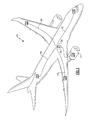
Figure 1 schematically illustrates an aircraft power distribution system. -
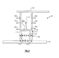
Figure 2 schematically illustrates an example circuit breaker module. -
Figure 3 schematically illustrates a first alternate example circuit breaker module. -
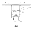
Figure 4 schematically illustrates a second alternate example circuit breaker module. -
Figure 1 schematically illustrates an aircraft 10. During operation of the aircraft 10, electric power is generated in agenerator 20 using mechanical rotation of ajet engine 22. The electric power generated in thegenerator 20 is transferred to apower distribution system 30 that usespower conduits 40 to distribute electric power to multiple on boardelectric systems 50. - Within the
power distribution system 30 are multiplecircuit breaker modules 32. Thecircuit breaker modules 32 are mounted to circuit boards in a power distribution panel and operate to prevent current through thepower distribution system 30 from exceeding pre-defined levels. As a result of this functionality, each of thecircuit breaker modules 32 incurs a voltage loss due to power absorption within the breaker circuitry. The power absorption in turn causes the breaker circuitry within the circuit breaker to generate heat. In order to prevent an undesirable buildup of heat within thecircuit breaker module 32, the heat is shunted to an attached circuit board and dissipated to ambient air using features of the attached circuit board. -
Figure 2 illustrates an examplecircuit breaker module 32 that can be used in the aircraft 10power distribution system 30 illustrated inFigure 1 . Thecircuit breaker module 32 includesconventional breaker circuitry 110 encased within ahousing 120. Twoelectric leads 112 extend from thebreaker circuitry 110 and through thehousing 120. Theelectric leads 112 connect thebreaker circuitry 110 to asocket 130. Thesocket 130, in turn, includes socket leads 132 that connect thebreaker circuitry 110 to acircuit board 140. - The
housing 120 of thecircuit breaker module 32 is capped by apower distribution panel 150. In alternate examples, thehousing 120 can include a dedicated cap in place of the illustratedpower distribution panel 150. In current circuit breaker module designs, thehousing 120 and thesocket 130 are constructed of an electrically insulating plastic material. The plastic used is a poor thermal conductor, and without proper heat dissipation, heat builds up to undesirable levels within thecircuit breaker module 32. Existing designs shunt heat from thebreaker circuitry 110 to thecircuit board 140 using only theelectric leads circuit board 140 to dissipate the heat in order to prevent heat build up. Utilization of theelectric leads leads circuit breaker module 32. - In contrast to conventional designs, the
circuit breaker module 32 includes multiple additional heat dissipation features. As a first heat dissipation feature, thehousing 120 of the illustratedcircuit breaker module 32 is constructed primarily of a thermally conductive polymer, such as CoolPoly E-series plastics. Thermally conductive polymers are defined as being polymers having a sufficient thermal conductivity to allow heat to dissipate through the thermally conductive polymer. As a result of thehousing 120 being constructed primarily of the thermally conductive polymer,heat dissipation paths 160 directly through thehousing 120 into the ambient air are created, thereby reducing heat transferred through theelectric leads leads housing 120 is electrically insulating. - As a second heat dissipation feature, the
socket 130 is similarly constructed primarily of the thermally conductive polymer. Thesocket 130 contacts thehousing 120 and creates athermal path 122 from thebreaker circuitry 110 to thecircuit board 140. Thethermal path 122 passes through thesocket 130 and is significantly larger than a thermal path provided solely by theelectric leads thermal path 122 connecting thebreaker circuitry 110 to thecircuit board 140, through thesocket 130, reduces the amount of heat transferred over theelectric leads leads leads socket 130 doubles as an adaptor and allows thecircuit breaker module 32 to connect to acircuit board 140 having a different lead configuration than the lead configuration of thecircuit breaker module 32. Between thesocket 130 and thecircuit board 140, a thermal interface material layer can be added which will enhance conduction heat transfer from thesocket 130 tocircuit board 140. In addition, this thermal interface material has two internal cut outs so theleads 112 can pass through it. -
Figure 3 illustrates an alternatecircuit breaker module 32, with an additional heat dissipation feature in the form ofheat fins 230. As in the examplecircuit breaker module 32 ofFigure 1 , thecircuit breaker module 32 hasbreaker circuitry 210 connected toelectric leads 212 extending from thebreaker circuitry 210. Ahousing 220 encapsulates thebreaker circuitry 210 and is constructed of a thermally conductive polymer, thereby allowing heat to dissipate through thehousing 220 into the ambient atmosphere. In addition to the features described above, the example ofFigure 3 includes multiple heat fins 230 connected to thehousing 220 of thecircuit breaker module 32. Theheat fins 230 can be integral to thehousing 220, or can be affixed to thehousing 220 using any known adhesion technique. When theheat fins 230 are integral to thehousing 220, theheat fins 230 are also constructed primarily of a thermally conductive polymer. When theheat fins 230 are adhered to thehousing 220 instead of integral to the housing, theheat fins 230 can be any suitably thermally conductive material. - While the
heat fins 230 are illustrated connected to a portion of thehousing 220 closest to theelectric leads 212, theheat fins 230 can be positioned anywhere on thehousing 220 and achieve the same benefit. The location of the heat fins 230 on thehousing 220, and the amount ofheat fins 230, can be adapted depending on the form factor requirements of the application in which the circuit breaker module is being used. - The heat fins 230 improve the heat dissipation of the
circuit breaker module 32 by increasing the surface area of thehousing 220 that is exposed to the ambient air, and thereby increasing the amount of heat that can be dissipated from thehousing 220 in a given time period. - In another example embodiment, the
heat fins 230 and thesocket 130 are combined, and thesocket 130 includes heat fins, thereby further increasing the surface area of the thermally conductive polymer exposed to the ambient air. -
Figure 4 illustrates another alternatecircuit breaker module 32. The alternatecircuit breaker module 32 ofFigure 4 includes a cooling shell as an additional heat dissipation feature. Thebreaker circuitry 310 and at least a portion of thehousing 320 are located within the coolingshell 330. The coolingshell 330 is connected to apanel surface 340. As with each of the previously described examples, thecircuit breaker module 32 includesbreaker circuitry 310 located within ahousing 320 constructed primarily of a thermally conductive polymer. Electric leads 312 extend through thehousing 320 and connect thebreaker circuitry 310 to a circuit board. Apanel surface 340 caps the top of thecircuit breaker module 32, thereby sealing thebreaker circuitry 310 inside. - The cooling
shell 330 extends from thepanel surface 340 and contacts the circuitbreaker module housing 320 along aninterior surface 332 of the coolingshell 330. Thepanel surface 340 and the coolingshell 330 are constructed of a highly thermally conductive material, such as aluminum, and provide an efficient thermal pathway directing heat generated in thebreaker circuit 310 through the circuitbreaker module housing 320 into the coolingshell 330 and then into thepanel surface 340. Heat is then dissipated from an exterior surface of the coolingshell 330 and multiple surfaces of thepanel surface 340 into the ambient air. Thus, the utilization of acooling shell 330 enhances the thermal conductivity of the thermallyconductive housing 320 and increases the ability of thecircuit breaker module 32 to dissipate heat. - While the illustrated configuration includes a
cooling shell 330 extending the full length of thecircuit breaker module 32, an alternate configuration can include acooling shell 330 that extends only partially along thehousing 320. Utilizing a partial cooling shell further allows theheat fins 230, illustrated inFigure 3 , to be included along with the coolingshell 330, thereby further enhancing the cooling capabilities of the circuit breaker module. - It is further understood that each of the above heat dissipation features can be used together or in any combination to provide a more efficient circuit breaker module.
- Although an embodiment of this invention has been disclosed, a worker of ordinary skill in this art would recognize that certain modifications would come within the scope of this invention. For that reason, the following claims should be studied to determine the true scope and content of this invention.
Claims (14)
- A circuit breaker module (32) comprising:a breaker circuit (110;210;310) connected to a first electrical lead (112;212;312) and a second electrical lead (112;212;312);a housing (120;220;320) surrounding said breaker circuit (110;210;310), wherein said first and second electrical leads (112;212;312) extend through said housing (120;220;320), and wherein said housing (120;220;320) is at least partially constructed of a thermally conductive polymer; anda heat dissipation feature contacting said housing (120;220;320), wherein said heat dissipation feature is operable to dissipate heat from said breaker circuit (110;210;310).
- The circuit breaker module of claim 1, wherein said heat dissipation feature is a socket (130) having a plurality of openings on a first side, each of said openings being operable to receive said first and second leads (112), and a plurality of socket leads (132) extending from a second side, wherein said first side of said socket (130) contacts said housing (120).
- The circuit breaker module of claim 2, wherein said socket (130) is constructed at least partially of a thermally conductive polymer.
- The circuit breaker module of claim 2 or 3, wherein said socket (130) further comprises a plurality of heat fins extending outwards from said housing.
- The circuit breaker module of claim 1, wherein said heat dissipation feature is a combination of a plurality of heat fins (230) extending from said housing and a thermally conductive socket connecting said housing to a circuit board.
- The circuit breaker module of claim 1, wherein said heat dissipation feature comprises a plurality of heat fins (230) extending outward from said housing.
- The circuit breaker module of claim 1, wherein said heat dissipation feature is a combination of a plurality of heat fins extending from said housing, and a cooling shell extending partially along said housing.
- The circuit breaker module of claim 7, wherein said heat dissipation feature further comprises a thermally conductive socket connecting said housing to a circuit board.
- The circuit breaker module of claim 2, 5 or 8, wherein said socket (130) is constructed at least partially of a thermally conductive polymer.
- The circuit breaker module of any of claims 4 to 9, wherein said heat fins are integral to said housing.
- The circuit breaker module of any of claims 4 to 9, wherein said heat fins are adhered to said housing.
- The circuit breaker module of any of claims 4 to 11 wherein said heat fins are constructed primarily of a thermally conductive polymer.
- The circuit breaker module of claim 1, wherein said heat dissipation feature is a thermally conducting cooling shell (330) and an interior surface of said cooling shell (330) contacts said housing (320) and a portion of said cooling shell (330) contacts a panel (340).
- An aircraft power distribution system (30) comprising:a generator (20) operable to generate electric power;a power distribution panel operable to distribute said electric power, wherein said power distribution panel includes a plurality of circuit breaker modules (32) of any preceding claim.
Applications Claiming Priority (1)
| Application Number | Priority Date | Filing Date | Title |
|---|---|---|---|
| US13/633,194 US9245699B2 (en) | 2012-10-02 | 2012-10-02 | Circuit breaker module |
Publications (2)
| Publication Number | Publication Date |
|---|---|
| EP2717285A1 true EP2717285A1 (en) | 2014-04-09 |
| EP2717285B1 EP2717285B1 (en) | 2017-12-13 |
Family
ID=49237112
Family Applications (1)
| Application Number | Title | Priority Date | Filing Date |
|---|---|---|---|
| EP13186428.2A Active EP2717285B1 (en) | 2012-10-02 | 2013-09-27 | Circuit Breaker Module |
Country Status (2)
| Country | Link |
|---|---|
| US (1) | US9245699B2 (en) |
| EP (1) | EP2717285B1 (en) |
Cited By (1)
| Publication number | Priority date | Publication date | Assignee | Title |
|---|---|---|---|---|
| EP3109957B1 (en) * | 2015-06-26 | 2020-08-19 | Hamilton Sundstrand Corporation | Power distribution panel having contactor with thermal management feature |
Families Citing this family (6)
| Publication number | Priority date | Publication date | Assignee | Title |
|---|---|---|---|---|
| US9153946B2 (en) * | 2012-09-25 | 2015-10-06 | Hamilton Sundstrand Corporation | Electrical contactor arrangement with thermal management |
| US9728347B2 (en) * | 2014-12-16 | 2017-08-08 | Hamilton Sundstrand Corporation | Integrated contactor mounting and power distribution system and method |
| US10405460B2 (en) * | 2016-04-08 | 2019-09-03 | Hamilton Sundstrand Corporation | Circuit breaker arrangements |
| US10270231B2 (en) | 2017-06-20 | 2019-04-23 | Hamilton Sundstrand Corporation | Integrated contactor mounting post |
| US11158998B1 (en) * | 2020-04-27 | 2021-10-26 | Abb Schweiz Ag | Heat sink for power supply panel |
| US12213287B2 (en) * | 2022-08-25 | 2025-01-28 | Siemens Industry, Inc. | Heat sink for a solid-state circuit breakerin an electrical panel |
Citations (4)
| Publication number | Priority date | Publication date | Assignee | Title |
|---|---|---|---|---|
| EP0531656A2 (en) * | 1991-09-11 | 1993-03-17 | Mitsubishi Denki Kabushiki Kaisha | Low-shrinkage unsaturated wet type polyester resin (B.M.C.) formulation composition having high thermal conductivity and molded circuit breaker and parts formed therefrom |
| JP2010272415A (en) * | 2009-05-22 | 2010-12-02 | Panasonic Electric Works Co Ltd | Switch device |
| EP2458697A2 (en) * | 2010-11-30 | 2012-05-30 | Hitachi Ltd. | Switch unit and switchgear equipped therewith |
| US20120182656A1 (en) * | 2011-01-14 | 2012-07-19 | Mustansir Kheraluwala | Active transient current control in electronic circuit breakers |
Family Cites Families (14)
| Publication number | Priority date | Publication date | Assignee | Title |
|---|---|---|---|---|
| JP2509471Y2 (en) * | 1988-07-19 | 1996-09-04 | モレックス インコーポレーテッド | Waterproof electrical connector |
| JPH1083753A (en) * | 1996-09-05 | 1998-03-31 | Yazaki Corp | Service plug |
| US6002580A (en) * | 1996-12-09 | 1999-12-14 | Power Distribution Products International | Circuit breaker power distribution panel |
| US6402572B1 (en) * | 1997-11-25 | 2002-06-11 | Hendry Mechanical Works | Electric switching device assembly system |
| US6086388A (en) * | 1998-05-05 | 2000-07-11 | Tvm Group, Inc. | Auxiliary switch system for use with removable circuit breaker |
| US6784783B2 (en) * | 2000-10-24 | 2004-08-31 | Cooper Technologies Company | Compact fused disconnect switch |
| US7476108B2 (en) * | 2004-12-22 | 2009-01-13 | Fci Americas Technology, Inc. | Electrical power connectors with cooling features |
| US7570146B2 (en) | 2007-07-25 | 2009-08-04 | Eaton Corporation | Circuit breaker including ambient compensation bimetal holding and releasing arc fault indicator |
| US8138864B2 (en) | 2009-06-01 | 2012-03-20 | Eaton Corporation | Circuit interrupter including a molded case made of liquid crystal polymer |
| US8094436B2 (en) * | 2010-03-29 | 2012-01-10 | Eaton Corporation | Plug-in circuit breaker assembly |
| EP2622270A1 (en) * | 2010-09-30 | 2013-08-07 | iLumisys, Inc. | Incandescent led replacement lamp |
| US8445800B2 (en) | 2010-12-17 | 2013-05-21 | Eaton Corporation | Electrical system, and circuit protection module and electrical switching apparatus therefor |
| US8514552B2 (en) | 2010-12-17 | 2013-08-20 | Eaton Corporation | Electrical system and matrix assembly therefor |
| US8649160B2 (en) * | 2012-02-07 | 2014-02-11 | Eaton Corporation | Plug-in circuit breaker assembly including insulative retainers |
-
2012
- 2012-10-02 US US13/633,194 patent/US9245699B2/en active Active
-
2013
- 2013-09-27 EP EP13186428.2A patent/EP2717285B1/en active Active
Patent Citations (4)
| Publication number | Priority date | Publication date | Assignee | Title |
|---|---|---|---|---|
| EP0531656A2 (en) * | 1991-09-11 | 1993-03-17 | Mitsubishi Denki Kabushiki Kaisha | Low-shrinkage unsaturated wet type polyester resin (B.M.C.) formulation composition having high thermal conductivity and molded circuit breaker and parts formed therefrom |
| JP2010272415A (en) * | 2009-05-22 | 2010-12-02 | Panasonic Electric Works Co Ltd | Switch device |
| EP2458697A2 (en) * | 2010-11-30 | 2012-05-30 | Hitachi Ltd. | Switch unit and switchgear equipped therewith |
| US20120182656A1 (en) * | 2011-01-14 | 2012-07-19 | Mustansir Kheraluwala | Active transient current control in electronic circuit breakers |
Cited By (1)
| Publication number | Priority date | Publication date | Assignee | Title |
|---|---|---|---|---|
| EP3109957B1 (en) * | 2015-06-26 | 2020-08-19 | Hamilton Sundstrand Corporation | Power distribution panel having contactor with thermal management feature |
Also Published As
| Publication number | Publication date |
|---|---|
| US9245699B2 (en) | 2016-01-26 |
| EP2717285B1 (en) | 2017-12-13 |
| US20140091617A1 (en) | 2014-04-03 |
Similar Documents
| Publication | Publication Date | Title |
|---|---|---|
| EP2717285B1 (en) | Circuit Breaker Module | |
| US9153946B2 (en) | Electrical contactor arrangement with thermal management | |
| US9142364B2 (en) | Contactor mounting panel with improved thermal characteristics | |
| US7837496B1 (en) | Contactor mounting assembly with improved thermal characteristics | |
| US9474189B2 (en) | Inverter device | |
| US9961758B1 (en) | Packaging a printed circuit board having a plurality of semiconductors in an inverter | |
| KR101343140B1 (en) | 3D power module package | |
| US9013065B2 (en) | Connecting mechanism arrangeable to a photovoltaic module | |
| US11464141B2 (en) | Power converter device for a vehicle, and vehicle | |
| EP3334254B1 (en) | Electric driver and illumination device | |
| US10103521B2 (en) | Electrical power distribution plate comprising a protected distribution bar | |
| US20230253636A1 (en) | Discharge apparatus for discharging energy, appliance apparatus having an electrical appliance and a discharge apparatus, method for operating and method for producing a discharge apparatus | |
| US11343942B2 (en) | Power conversion device including cooling components | |
| CN102447354B (en) | Variable-frequency motor, frequency converter and heat radiation member | |
| CN106016119A (en) | Light source module | |
| CN103329640B (en) | Electrical system and matrix assemblies thereof | |
| CN107074168B (en) | LDC Integrated Junction Box | |
| JP7411910B2 (en) | Cooling structure, charging device, and vehicle | |
| KR101901134B1 (en) | Capacitor case structure | |
| US8536698B2 (en) | Semiconductor device | |
| US10499514B2 (en) | Vehicular control device | |
| CN102412077A (en) | Thyristor electronic switch | |
| KR101608360B1 (en) | The bus bar of junction box | |
| WO2018209605A1 (en) | Brushless electric tool | |
| JP2008270528A (en) | Structure of semiconductor module |
Legal Events
| Date | Code | Title | Description |
|---|---|---|---|
| PUAI | Public reference made under article 153(3) epc to a published international application that has entered the european phase |
Free format text: ORIGINAL CODE: 0009012 |
|
| AK | Designated contracting states |
Kind code of ref document: A1 Designated state(s): AL AT BE BG CH CY CZ DE DK EE ES FI FR GB GR HR HU IE IS IT LI LT LU LV MC MK MT NL NO PL PT RO RS SE SI SK SM TR |
|
| AX | Request for extension of the european patent |
Extension state: BA ME |
|
| 17P | Request for examination filed |
Effective date: 20141007 |
|
| RBV | Designated contracting states (corrected) |
Designated state(s): AL AT BE BG CH CY CZ DE DK EE ES FI FR GB GR HR HU IE IS IT LI LT LU LV MC MK MT NL NO PL PT RO RS SE SI SK SM TR |
|
| GRAP | Despatch of communication of intention to grant a patent |
Free format text: ORIGINAL CODE: EPIDOSNIGR1 |
|
| STAA | Information on the status of an ep patent application or granted ep patent |
Free format text: STATUS: GRANT OF PATENT IS INTENDED |
|
| INTG | Intention to grant announced |
Effective date: 20170811 |
|
| GRAS | Grant fee paid |
Free format text: ORIGINAL CODE: EPIDOSNIGR3 |
|
| GRAA | (expected) grant |
Free format text: ORIGINAL CODE: 0009210 |
|
| STAA | Information on the status of an ep patent application or granted ep patent |
Free format text: STATUS: THE PATENT HAS BEEN GRANTED |
|
| AK | Designated contracting states |
Kind code of ref document: B1 Designated state(s): AL AT BE BG CH CY CZ DE DK EE ES FI FR GB GR HR HU IE IS IT LI LT LU LV MC MK MT NL NO PL PT RO RS SE SI SK SM TR |
|
| REG | Reference to a national code |
Ref country code: GB Ref legal event code: FG4D |
|
| REG | Reference to a national code |
Ref country code: AT Ref legal event code: REF Ref document number: 955124 Country of ref document: AT Kind code of ref document: T Effective date: 20171215 Ref country code: CH Ref legal event code: EP |
|
| REG | Reference to a national code |
Ref country code: IE Ref legal event code: FG4D |
|
| REG | Reference to a national code |
Ref country code: DE Ref legal event code: R096 Ref document number: 602013030695 Country of ref document: DE |
|
| REG | Reference to a national code |
Ref country code: NL Ref legal event code: MP Effective date: 20171213 |
|
| REG | Reference to a national code |
Ref country code: LT Ref legal event code: MG4D |
|
| PG25 | Lapsed in a contracting state [announced via postgrant information from national office to epo] |
Ref country code: NO Free format text: LAPSE BECAUSE OF FAILURE TO SUBMIT A TRANSLATION OF THE DESCRIPTION OR TO PAY THE FEE WITHIN THE PRESCRIBED TIME-LIMIT Effective date: 20180313 Ref country code: SE Free format text: LAPSE BECAUSE OF FAILURE TO SUBMIT A TRANSLATION OF THE DESCRIPTION OR TO PAY THE FEE WITHIN THE PRESCRIBED TIME-LIMIT Effective date: 20171213 Ref country code: FI Free format text: LAPSE BECAUSE OF FAILURE TO SUBMIT A TRANSLATION OF THE DESCRIPTION OR TO PAY THE FEE WITHIN THE PRESCRIBED TIME-LIMIT Effective date: 20171213 Ref country code: LT Free format text: LAPSE BECAUSE OF FAILURE TO SUBMIT A TRANSLATION OF THE DESCRIPTION OR TO PAY THE FEE WITHIN THE PRESCRIBED TIME-LIMIT Effective date: 20171213 |
|
| REG | Reference to a national code |
Ref country code: AT Ref legal event code: MK05 Ref document number: 955124 Country of ref document: AT Kind code of ref document: T Effective date: 20171213 |
|
| PG25 | Lapsed in a contracting state [announced via postgrant information from national office to epo] |
Ref country code: BG Free format text: LAPSE BECAUSE OF FAILURE TO SUBMIT A TRANSLATION OF THE DESCRIPTION OR TO PAY THE FEE WITHIN THE PRESCRIBED TIME-LIMIT Effective date: 20180313 Ref country code: RS Free format text: LAPSE BECAUSE OF FAILURE TO SUBMIT A TRANSLATION OF THE DESCRIPTION OR TO PAY THE FEE WITHIN THE PRESCRIBED TIME-LIMIT Effective date: 20171213 Ref country code: GR Free format text: LAPSE BECAUSE OF FAILURE TO SUBMIT A TRANSLATION OF THE DESCRIPTION OR TO PAY THE FEE WITHIN THE PRESCRIBED TIME-LIMIT Effective date: 20180314 Ref country code: LV Free format text: LAPSE BECAUSE OF FAILURE TO SUBMIT A TRANSLATION OF THE DESCRIPTION OR TO PAY THE FEE WITHIN THE PRESCRIBED TIME-LIMIT Effective date: 20171213 Ref country code: HR Free format text: LAPSE BECAUSE OF FAILURE TO SUBMIT A TRANSLATION OF THE DESCRIPTION OR TO PAY THE FEE WITHIN THE PRESCRIBED TIME-LIMIT Effective date: 20171213 |
|
| PG25 | Lapsed in a contracting state [announced via postgrant information from national office to epo] |
Ref country code: NL Free format text: LAPSE BECAUSE OF FAILURE TO SUBMIT A TRANSLATION OF THE DESCRIPTION OR TO PAY THE FEE WITHIN THE PRESCRIBED TIME-LIMIT Effective date: 20171213 |
|
| PG25 | Lapsed in a contracting state [announced via postgrant information from national office to epo] |
Ref country code: ES Free format text: LAPSE BECAUSE OF FAILURE TO SUBMIT A TRANSLATION OF THE DESCRIPTION OR TO PAY THE FEE WITHIN THE PRESCRIBED TIME-LIMIT Effective date: 20171213 Ref country code: SK Free format text: LAPSE BECAUSE OF FAILURE TO SUBMIT A TRANSLATION OF THE DESCRIPTION OR TO PAY THE FEE WITHIN THE PRESCRIBED TIME-LIMIT Effective date: 20171213 Ref country code: CZ Free format text: LAPSE BECAUSE OF FAILURE TO SUBMIT A TRANSLATION OF THE DESCRIPTION OR TO PAY THE FEE WITHIN THE PRESCRIBED TIME-LIMIT Effective date: 20171213 Ref country code: EE Free format text: LAPSE BECAUSE OF FAILURE TO SUBMIT A TRANSLATION OF THE DESCRIPTION OR TO PAY THE FEE WITHIN THE PRESCRIBED TIME-LIMIT Effective date: 20171213 Ref country code: CY Free format text: LAPSE BECAUSE OF FAILURE TO SUBMIT A TRANSLATION OF THE DESCRIPTION OR TO PAY THE FEE WITHIN THE PRESCRIBED TIME-LIMIT Effective date: 20171213 |
|
| REG | Reference to a national code |
Ref country code: FR Ref legal event code: PLFP Year of fee payment: 6 |
|
| PG25 | Lapsed in a contracting state [announced via postgrant information from national office to epo] |
Ref country code: SM Free format text: LAPSE BECAUSE OF FAILURE TO SUBMIT A TRANSLATION OF THE DESCRIPTION OR TO PAY THE FEE WITHIN THE PRESCRIBED TIME-LIMIT Effective date: 20171213 Ref country code: PL Free format text: LAPSE BECAUSE OF FAILURE TO SUBMIT A TRANSLATION OF THE DESCRIPTION OR TO PAY THE FEE WITHIN THE PRESCRIBED TIME-LIMIT Effective date: 20171213 Ref country code: AT Free format text: LAPSE BECAUSE OF FAILURE TO SUBMIT A TRANSLATION OF THE DESCRIPTION OR TO PAY THE FEE WITHIN THE PRESCRIBED TIME-LIMIT Effective date: 20171213 Ref country code: IT Free format text: LAPSE BECAUSE OF FAILURE TO SUBMIT A TRANSLATION OF THE DESCRIPTION OR TO PAY THE FEE WITHIN THE PRESCRIBED TIME-LIMIT Effective date: 20171213 Ref country code: RO Free format text: LAPSE BECAUSE OF FAILURE TO SUBMIT A TRANSLATION OF THE DESCRIPTION OR TO PAY THE FEE WITHIN THE PRESCRIBED TIME-LIMIT Effective date: 20171213 Ref country code: IS Free format text: LAPSE BECAUSE OF FAILURE TO SUBMIT A TRANSLATION OF THE DESCRIPTION OR TO PAY THE FEE WITHIN THE PRESCRIBED TIME-LIMIT Effective date: 20180413 |
|
| REG | Reference to a national code |
Ref country code: DE Ref legal event code: R097 Ref document number: 602013030695 Country of ref document: DE |
|
| PLBE | No opposition filed within time limit |
Free format text: ORIGINAL CODE: 0009261 |
|
| STAA | Information on the status of an ep patent application or granted ep patent |
Free format text: STATUS: NO OPPOSITION FILED WITHIN TIME LIMIT |
|
| 26N | No opposition filed |
Effective date: 20180914 |
|
| PG25 | Lapsed in a contracting state [announced via postgrant information from national office to epo] |
Ref country code: DK Free format text: LAPSE BECAUSE OF FAILURE TO SUBMIT A TRANSLATION OF THE DESCRIPTION OR TO PAY THE FEE WITHIN THE PRESCRIBED TIME-LIMIT Effective date: 20171213 |
|
| PG25 | Lapsed in a contracting state [announced via postgrant information from national office to epo] |
Ref country code: SI Free format text: LAPSE BECAUSE OF FAILURE TO SUBMIT A TRANSLATION OF THE DESCRIPTION OR TO PAY THE FEE WITHIN THE PRESCRIBED TIME-LIMIT Effective date: 20171213 |
|
| PG25 | Lapsed in a contracting state [announced via postgrant information from national office to epo] |
Ref country code: MC Free format text: LAPSE BECAUSE OF FAILURE TO SUBMIT A TRANSLATION OF THE DESCRIPTION OR TO PAY THE FEE WITHIN THE PRESCRIBED TIME-LIMIT Effective date: 20171213 |
|
| REG | Reference to a national code |
Ref country code: CH Ref legal event code: PL |
|
| GBPC | Gb: european patent ceased through non-payment of renewal fee |
Effective date: 20180927 |
|
| REG | Reference to a national code |
Ref country code: BE Ref legal event code: MM Effective date: 20180930 |
|
| REG | Reference to a national code |
Ref country code: IE Ref legal event code: MM4A |
|
| PG25 | Lapsed in a contracting state [announced via postgrant information from national office to epo] |
Ref country code: LU Free format text: LAPSE BECAUSE OF NON-PAYMENT OF DUE FEES Effective date: 20180927 |
|
| PG25 | Lapsed in a contracting state [announced via postgrant information from national office to epo] |
Ref country code: IE Free format text: LAPSE BECAUSE OF NON-PAYMENT OF DUE FEES Effective date: 20180927 |
|
| PG25 | Lapsed in a contracting state [announced via postgrant information from national office to epo] |
Ref country code: BE Free format text: LAPSE BECAUSE OF NON-PAYMENT OF DUE FEES Effective date: 20180930 Ref country code: CH Free format text: LAPSE BECAUSE OF NON-PAYMENT OF DUE FEES Effective date: 20180930 Ref country code: LI Free format text: LAPSE BECAUSE OF NON-PAYMENT OF DUE FEES Effective date: 20180930 |
|
| PG25 | Lapsed in a contracting state [announced via postgrant information from national office to epo] |
Ref country code: GB Free format text: LAPSE BECAUSE OF NON-PAYMENT OF DUE FEES Effective date: 20180927 |
|
| PG25 | Lapsed in a contracting state [announced via postgrant information from national office to epo] |
Ref country code: MT Free format text: LAPSE BECAUSE OF NON-PAYMENT OF DUE FEES Effective date: 20180927 |
|
| PG25 | Lapsed in a contracting state [announced via postgrant information from national office to epo] |
Ref country code: TR Free format text: LAPSE BECAUSE OF FAILURE TO SUBMIT A TRANSLATION OF THE DESCRIPTION OR TO PAY THE FEE WITHIN THE PRESCRIBED TIME-LIMIT Effective date: 20171213 |
|
| PG25 | Lapsed in a contracting state [announced via postgrant information from national office to epo] |
Ref country code: PT Free format text: LAPSE BECAUSE OF FAILURE TO SUBMIT A TRANSLATION OF THE DESCRIPTION OR TO PAY THE FEE WITHIN THE PRESCRIBED TIME-LIMIT Effective date: 20171213 Ref country code: HU Free format text: LAPSE BECAUSE OF FAILURE TO SUBMIT A TRANSLATION OF THE DESCRIPTION OR TO PAY THE FEE WITHIN THE PRESCRIBED TIME-LIMIT; INVALID AB INITIO Effective date: 20130927 |
|
| PG25 | Lapsed in a contracting state [announced via postgrant information from national office to epo] |
Ref country code: MK Free format text: LAPSE BECAUSE OF NON-PAYMENT OF DUE FEES Effective date: 20171213 |
|
| PG25 | Lapsed in a contracting state [announced via postgrant information from national office to epo] |
Ref country code: AL Free format text: LAPSE BECAUSE OF FAILURE TO SUBMIT A TRANSLATION OF THE DESCRIPTION OR TO PAY THE FEE WITHIN THE PRESCRIBED TIME-LIMIT Effective date: 20171213 |
|
| P01 | Opt-out of the competence of the unified patent court (upc) registered |
Effective date: 20230522 |
|
| PGFP | Annual fee paid to national office [announced via postgrant information from national office to epo] |
Ref country code: DE Payment date: 20250820 Year of fee payment: 13 |
|
| PGFP | Annual fee paid to national office [announced via postgrant information from national office to epo] |
Ref country code: FR Payment date: 20250821 Year of fee payment: 13 |