EP2717280A1 - Transformer termination and interconnection assembly - Google Patents
Transformer termination and interconnection assembly Download PDFInfo
- Publication number
- EP2717280A1 EP2717280A1 EP13186523.0A EP13186523A EP2717280A1 EP 2717280 A1 EP2717280 A1 EP 2717280A1 EP 13186523 A EP13186523 A EP 13186523A EP 2717280 A1 EP2717280 A1 EP 2717280A1
- Authority
- EP
- European Patent Office
- Prior art keywords
- assembly
- coil winding
- transformer
- substrate
- bobbin
- Prior art date
- Legal status (The legal status is an assumption and is not a legal conclusion. Google has not performed a legal analysis and makes no representation as to the accuracy of the status listed.)
- Withdrawn
Links
- 238000004804 winding Methods 0.000 claims abstract description 133
- 239000000758 substrate Substances 0.000 claims abstract description 91
- 230000000712 assembly Effects 0.000 claims description 25
- 238000000429 assembly Methods 0.000 claims description 25
- 230000000717 retained effect Effects 0.000 claims description 5
- 230000013011 mating Effects 0.000 description 6
- 229910000679 solder Inorganic materials 0.000 description 2
- 230000003750 conditioning effect Effects 0.000 description 1
- 238000002788 crimping Methods 0.000 description 1
- 230000001419 dependent effect Effects 0.000 description 1
- 230000010354 integration Effects 0.000 description 1
- 238000004519 manufacturing process Methods 0.000 description 1
- 239000000463 material Substances 0.000 description 1
- 230000004048 modification Effects 0.000 description 1
- 238000012986 modification Methods 0.000 description 1
- 238000005476 soldering Methods 0.000 description 1
- 230000001131 transforming effect Effects 0.000 description 1
Images


Classifications
-
- H—ELECTRICITY
- H01—ELECTRIC ELEMENTS
- H01F—MAGNETS; INDUCTANCES; TRANSFORMERS; SELECTION OF MATERIALS FOR THEIR MAGNETIC PROPERTIES
- H01F27/00—Details of transformers or inductances, in general
- H01F27/28—Coils; Windings; Conductive connections
- H01F27/29—Terminals; Tapping arrangements for signal inductances
-
- H—ELECTRICITY
- H01—ELECTRIC ELEMENTS
- H01F—MAGNETS; INDUCTANCES; TRANSFORMERS; SELECTION OF MATERIALS FOR THEIR MAGNETIC PROPERTIES
- H01F27/00—Details of transformers or inductances, in general
- H01F27/28—Coils; Windings; Conductive connections
- H01F27/32—Insulating of coils, windings, or parts thereof
- H01F27/324—Insulation between coil and core, between different winding sections, around the coil; Other insulation structures
- H01F27/325—Coil bobbins
Definitions
- a transformer assembly comprises a magnetic core assembly, a bobbin assembly, a coil winding, a transformer interconnect trace, and a coil winding terminal post.
- the bobbin assembly includes a coil winding assembly disposed around a portion of the magnetic core assembly. The coil winding is retained in the coil winding assembly and spaced apart from the magnetic core assembly.
- the transformer interconnect trace is fixed to a substrate secured to the transformer assembly proximate the bobbin assembly.
- the coil winding terminal post receives a coil winding end for electrically connecting the coil winding end to the transformer interconnect trace through the coil winding terminal post.
- a transformer interconnect assembly comprises a plurality of transformer interconnect traces fixed to a substrate, and a corresponding plurality of coil winding terminal posts. Each post has a receiving end for receiving a coil winding end, and a mounting end for electrically connecting the coil winding end to the transformer interconnect trace through the coil winding terminal post.
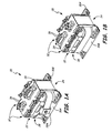
- FIGS. 1A and 1B show respective forward and rear perspective views of an example transformer assembly 20, and also include magnetic core assembly 22, bobbin section 24, band 28, buckle 28A, mounting brackets 30A, 30B, coil winding terminal posts 32, substrate 34, and post substrate end 36.
- Transformer assembly 20 includes magnetic core assembly 22 and bobbin section 24.
- Bobbin section 24 can be secured in various ways to magnetic core assembly 22 with band 28 and buckle 28A extending around brackets 30A, 30B for holding magnetic core assembly 22 to bobbin section 24.
- Bobbin section 24 can include one or more bobbin assemblies retaining at least one coil winding assembly (not visible in FIGS. 1A and 1B ) around at least one portion of magnetic core 22.
- each coil winding assembly includes a coil of magnet wire wound several times around a winding body that retains the coil winding around and spaced apart from one or more legs of magnetic core assembly 22.
- At least some of the coil winding terminal posts 32 receive either a first or second coil winding end (not visible in FIGS. 1A and 1B ).
- Substrate 34 is disposed proximate to bobbin section 24 and terminal posts 32.
- Substrate 34 includes a plurality of transformer interconnect traces (omitted for clarity) integrally fixed or printed thereon.
- Substrate end 36 of at least one of the coil winding terminal posts 32 is electrically connected to substrate 34 as described below.
- each transformer interconnect trace (omitted for clarity from FIGS. 1A and 1B ) extends along substrate 34 from a terminal end of the interconnect trace, located at or near the electrical connection with post substrate end 36.
- Example arrangements and details of various transformer, bobbin, and coil winding assemblies are shown and described below.
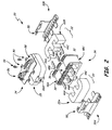
- FIG. 2 is an exploded view of the example embodiment of transformer assembly 20 shown in FIGS. 1A and 1B .
- FIG. 2 also includes magnetic core assembly segments 22A, 22B, bobbin section 24, band 28, buckle 28A, mounting brackets 30A, 30B, coil winding terminal posts 32, substrate 34, post substrate end 36, magnetic core legs 44A, 44B, 44C, bobbin assemblies 48A, 48B, 48C, bracket tab 50, substrate flange 52, shims 54, first electrical interface 56, second electrical interface 58, and transformer interconnect assembly 60.
- magnetic core assembly 22 includes two core segments 22A, 22B.
- Each core segment 22A, 22B may be E-shaped with respective pluralities of legs 44A, 44B, 44C arranged adjacent to each other as shown in FIG. 2 .
- Bobbin section 24 includes a plurality of generally rectangular bobbin assemblies 48A, 48B, 48C arranged over respective legs 44A, 44B, 44C of E-shaped core segments 22A, 22B.
- each rectangular bobbin assembly 48A, 48B, 48C includes at least one coil winding assembly disposed around a different portion of magnetic core assembly segments 22A, 22B.
- bobbin assemblies 48A, 48B, 48C can each retain at least one separate coil winding around different legs 44A, 44B, 44C of magnetic core assembly segments 22A, 22B.
- Brackets 30A, 30B extends around brackets 30A, 30B to hold rectangular bobbin assemblies 48A, 48B, 48C over respective legs 44A, 44B, 44C of magnetic core segments 22A, 22B.
- Substrate 34 can be removably fastened to brackets 30A, 30B at tabs 50 and flanges 52 using standard screws 59. Shims 54 can reduce the clearance between core legs 44A, 44B, 44C and bobbin assemblies 48A, 48B, 48C.
- One or both brackets 30A, 30B can be secured to a component, support frame, or other structure before, during or after assembly of transformer 20.
- Each electrical interface 56, 58 can be any type of connector interface suitable for integrating transformer assembly 20 into a particular electrical system.
- Example families of plug-and-receptacle connector interfaces are described in a commonly assigned U.S. Patent Application entitled “High Voltage Connector Interfaces", filed on an even date herewith. Such connector interfaces are suitable for high voltage, high altitude use in aircraft.
- Other standardized or customized electrical interfaces can also be adapted for use in various embodiments.
- Transformer interconnect assembly 60 In addition to bobbin assembly 48 including at least one coil winding assembly retaining coil windings around and spaced apart from a portion of magnetic core assembly 22 transformer assembly 20 also includes transformer interconnect assembly 60 (shown in FIG. 3A ). Transformer interconnect assembly 60 generally includes a plurality of transformer interconnect traces (shown in FIG. 3A ) fixed to a substrate 34 to simplify integration with external circuitry and components. Substrate 34 is secured to transformer assembly 20 proximate bobbin assembly 24. Transformer interconnect assembly 60 also generally includes a corresponding plurality of coil winding terminal posts 32 receiving a coil winding end (shown in FIG. 3C ) for electrically connecting the coil winding end to the transformer interconnect trace through coil winding terminal post 32. At least one of the plurality of transformer interconnect traces extends along the substrate from an interconnect terminal electrically connected to substrate end 36 of each coil winding terminal post 32.
- a terminal interconnect assembly as described herein can eliminate the need for these splices.
- the interconnections can be fixed to a substrate, such as a printed wiring board, which replaces separate interconnection wires that have previously been individually spliced.
- the coil winding terminal posts can be disposed proximate to the substrate, such as on a bobbin assembly, and/or on the substrate itself, to connect the magnet coil windings to interconnection contacts on the substrate.
- the fixed transformer interconnect traces can be configured in various orientations to form one or more integrated circuits intended to control operation of the transformer assembly relative to the electrical interfaces (e.g., interfaces 56, 58). Two non-limiting example embodiments of a terminal interconnect assembly are described in this specification.
- FIG. 3A is a magnified view of one embodiment of transformer interconnect assembly 60.
- FIG. 3B is an exploded view of transformer assembly 20 with substrate 34 spaced apart from the rest of assembly 20.
- FIGS. 3A-3C also include coil winding terminal posts 32, substrate 34, post substrate end 36, bobbin assemblies 48A, 48B, 48C, first electrical interface 56, second electrical interface 58, transformer interconnect assembly 60, coil winding ends 62, terminal receiving end 63, coil winding guides 64, substrate contacts 66, substrate mounting holes 68, substrate interconnect traces 70, interface pin contacts 72, interface shells 74, and socket contacts 76.
- FIGS. 3A-3C illustrate a first part of example transformer interconnect assembly 60 proximate substrate 34 while FIGS. 4A-4B show details around a second part proximate bobbin assemblies 48A, 48B, 48C.
- transformer interconnect assembly 60 includes a plurality of coil winding terminal posts 32 disposed proximate to substrate 34 for receiving a corresponding plurality of coil winding ends 62.
- Coil winding ends 62 extend from at least one coil winding assembly (not visible in FIGS. 3A-3C ) disposed in each bobbin assembly 48A, 48B, 48C.
- Certain embodiments of the bobbin assembly can have a plurality of coil windings, which may be nested as shown in FIGS. 4A-4B .
- coil winding terminal posts 32 each have terminal receiving end 63 and mounting/substrate end 36.
- Coil winding terminal posts 32 can be mounted to at least one of the multiple bobbin assemblies 48A, 48B, 48C so as to maintain proximity with substrate 34.
- a plurality of coil winding terminal posts can additionally or alternatively be mounted directly to the substrate, such as is shown in FIGS. 5A-5C .
- the plurality of posts 32 can be integrally molded into bobbin assemblies 48A, 48B, 48C to simplify manufacture of the entire assembly.
- Coil winding ends 62 (shown in FIG. 3C ) can extend out from around winding guides 64, which may also be integrally molded to one or more of bobbin assemblies 48A, 48B, 48C. Coil winding ends 62 can be received by winding terminal posts 32 at receiving ends 63.
- Terminal post substrate ends 36 are also in electrical contact with substrate 34 by being secured atop bobbin assemblies 48A, 48B, 48C.
- Each terminal post 32 which may for example be a lead pin, can be electrically connected via mounting/substrate end 36 to a corresponding substrate contact 66. Some or all of these contacts 66 can be disposed in holes 68 formed through substrate 34.
- Each substrate contact 66 can form a terminal end of at least one fixed transformer interconnect trace 70.
- Mounting/substrate end 36 can thus extend through a corresponding plurality of holes 68 and engage substrate contacts 66 in order to electrically connect bobbin assemblies 48A, 48B, 48C to interconnect traces 70.
- substrate ends 36 can be pressed or soldered in to substrate 34.
- Substrate 34 can be generally any type of circuit board with interconnect traces 70 fixed thereto.
- substrate 34 is a printed wiring board (PWB) such that interconnect traces 70 are integrated, or printed thereon.
- PWB printed wiring board
- Each interconnect trace 70 directly or indirectly connects the respective coil winding terminal posts 32 (via substrate contact 66) to another location in the circuit such as one or both electrical interfaces 56, 58.
- electrical interfaces 56, 58 may be any suitable plug or receptacle configured to engage a corresponding receptacle or plug disposed on a wire harness, circuit board, printed wiring board or any other suitable electrical component (not shown).
- one or both electrical interfaces 56, 58 can include a plurality of spaced apart pin contacts 72 retained in shell 74 and secured to substrate 34.
- Pin contacts 72 have a mating socket contact 76 (e.g., either can be a pin or socket) for mating with corresponding mating socket contacts 76 (e.g., either can be a socket or pin) on the corresponding receptacle or plug (not shown). All contacts also have a tail end (not visible in FIGS. 3A-3B ) diametrically opposed to mating end, and electrically connected to one or more interconnect traces 70.
- transformer assembly 20 can send incoming bus power to transformer assembly 20 (shown in FIG. 2 ).
- Second interface 58 can operate as a control for the circuitry of transformer assembly 20, as well as receiving a typically lower outlet voltage suitable for operating one or more aircraft components.
- transformer assembly 20 (shown in FIGS. 1A, 1B , and 2 ) is configured to condition and transform three-phase alternating current, with each coil winding assembly 48A, 48B, 48C dedicated to conditioning and transforming of one of those phases into a useful low-voltage current.
- not all interconnect traces 70 need to directly link a tail contact 72 with a coil winding end 62.
- some interconnect traces 70 can direct received signals via one or more tail contacts 72 to control integrated switches or diodes disposed on substrate 34. These switches can be configured to operate different sets of coil windings to achieve different step-down or step-up voltages on each phase. It will also be recognized that FIGS. 3A and 3B only depict a few interconnect traces 70 with many that have been moved or omitted to improve the view of remaining elements. One skilled in the art will be able to readily adapt these teachings to particular arrangements of interconnect traces 70.
- Electrical interfaces 56, 58 are shown in this example as being two separate interfaces. However, it will be appreciated that substrate 34 can include a single interface with multiple tail contacts for performing both functions. It will also be recognized that yet other embodiments can include more than two electrical interfaces.
- FIG. 3C shows a magnified view of interconnect assembly 60 at a second end of coil winding terminal posts 32.
- coil winding terminal posts 32 can be integrally molded onto one or more bobbin assemblies 48A, 48B, 48C to maintain proximity to substrate 34.
- Posts 32 can be electrically connected to substrate 34 and interconnect traces 70 at post substrate end 36.
- at least one of the post receiving ends 63 each has coil winding end 62 conductively connected and secured thereto. This may be done by crimping, soldering or any other suitable conductive interface.
- Coil winding ends 62 are ends of magnet wire wound within example bobbin assembly 48A to form coil windings 80A, 80B, 80C, 80D, 80E retained around core leg 22A.
- Coil windings 80A, 80B, 80C, 80D, 80E can be nested to form nested coil winding assembly 82 using a plurality of nested coil winding bodies.
- Bodies 84A, 84B, 84C are visible in this cross-section, but are shown in more detail in FIGS. 4A and 4B .
- each coil winding 80A, 80B, 80C, 80D, 80E is electrically connected through interconnect traces 70 to one or both electrical interfaces 56, 58. This is a far simpler and more mistake-resistant interconnection arrangement as compared to traditional interconnections requiring individually splicing each coil winding magnet wire to individual interconnect wires or harnesses.
- FIG. 4A shows a portion of bobbin assembly 48A with an example nested coil winding body assembly 83.
- FIG. 4B is an exploded view of nested coil winding body assembly 83.
- FIGS. 4A and 4B also include coil winding terminal posts 32, post substrate end 36, terminal post receiving ends 63, coil winding guides 64, nested winding bodies 84A, 84B, 84C, 84D, 84E, outlet ports 88, and bobbin body end flanges 90A, 90B.
- Nested coil winding body assembly 83 includes in this example, a plurality of nested coil winding bodies 84A, 84B, 84C, 84D, 84E.
- Each body 84A, 84B, 84C, 84D, 84E supports by nested windings 80A, 80B, 80C, 80D, 80E (shown in FIG. 3C ).
- a separate length of magnet wire can be wound around each of the nested winding bodies 84A, 84B, 84C, 84D, 84E, which are then inserted into one another generally in the arrangement shown in FIG. 4B . As was shown in FIG.
- windings 80A, 80B, 80C, 80D, 80D, 80E can be arranged such that coil winding ends 62 can be aligned with outlet ports 88 formed into bobbin assembly 48A, which are then conductively connected to respective terminal post receiving ends 63.
- Bobbin assembly 48A can also include a bobbin portion with integral end flanges 90A, 90B so that these nested coil winding assemblies 84A, 84B, 84C, 84D, 84E can be placed over an interior portion of the bobbin and retained.
- FIG. 5A is an isometric view of a transformer assembly 120 with a second non-limiting example interconnect assembly 160.
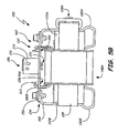
- FIG. 5B is a side elevation view of transformer assembly 120.
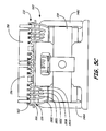
- FIG. 5C is a front elevation view of transformer assembly 120.
- FIGS. 5A-5C also include magnetic core assembly 120 with segments 122A, 122B, bobbin section 124, band 128, buckle 128A, brackets 130A, 130B, coil winding terminal posts 132, substrate 134 post substrate ends 136, core legs 144A, 144B, 144C, bobbin assemblies 148A, 148B, 148C, bracket tabs 150, substrate flanges 152, dielectric shims 154, electrical interfaces 156, 158, coil winding ends 162, post receiving ends 163, substrate contact 166, electrical interface pin contacts 172, interface shells 174, socket mating ends 176, and coil windings 180A, 180B, 180C, 180D, 180E.
- FIGS. 1A, 1B , and 2 show a first example embodiment of transformer assembly 20 with magnetic core assembly 22 and bobbin section 24 with a plurality of bobbin assemblies retaining at least one coil winding assembly around at least one portion of magnetic core assembly 22.
- FIGS. 5A , 5B , and 5C show a similar arrangement of transformer assembly 120 with magnetic core assembly segments 122A, 122B and bobbin section 124 secured via band 128 extending around brackets 130A, 130B.
- Substrate 134 can be removably fastened to brackets 130A, 130B at tabs 150 and flanges 152 using standard screws 159 over bobbin assemblies 148A, 148B, 148C.
- Dielectric shims 154 reduce clearance between core legs 144A, 144B, 144C and bobbin assembly 148A, 148B, 148C.
- Other like reference numbers correspond to similar arrangements described with respect to the first non-limiting example above.
- each bobbin assembly 148A, 148B, 148C can include one or more coil winding assemblies. These coil winding assemblies may be nested as shown in FIGS. 4A and 4B with one or more coil windings 180A, 180B, 180C, 180D, 180E each wound several times around a respective one or more legs 144A, 144B, 144C of E-shaped core segments 122A, 122B.
- transformer interconnect assembly 160 includes a plurality of coil winding terminal posts 132 disposed proximate to substrate 134 for receiving a corresponding plurality of coil winding ends 162.
- this second non-limiting example embodiment shows the plurality of coil winding terminal posts 132 mounted directly onto substrate 134 via substrate contacts 166.
- substrate ends 136 of posts 132 can be integral with substrate contacts 166
- FIG. 3A shows transformer interconnect trace 70 extending from a terminal end of the interconnect trace (e.g. substrate contact 66) along substrate 34.
- This second example embodiment shown in FIGS. 5A-5C can include a similar arrangement of a plurality of transformer interconnect traces (omitted for clarity) integrally fixed or printed onto substrate 134, which connect respective coil winding terminal posts 132 via substrate contacts 166) to another location on the circuit. These interconnect traces directly or indirectly join coil winding ends 162 through the circuit to one or both electrical interfaces 156, 158.
- Electrical interfaces 156, 158 may be a plug or receptacle configured to engage a corresponding receptacle or plug disposed on a wire harness, circuit board, printed wiring board or any other suitable electrical component as described above (not shown). These example electrical interfaces 156, 158 show different arrangements of pin contacts 172, shells 174, and socket contact mating ends 176 as compared to the earlier example. As explained above, the electrical interfaces (including interfaces 156, 158) can be a standardized or customized interface dependent on the particular electrical system into which the particular embodiment of the transformer assembly is being installed.
- substrate contact 166 in this second example embodiment is disposed directly at the base of terminal posts 132 (post terminal end 166).
- the one or more coil windings 180A, 180B, 180C, 180D extend farther upward and over the top of substrate 134.
- Winding guides 164 in this example can be formed as grooves along the sides of substrate 134 to direct and retain coil windings 180A, 180B, 180C, 180D, 180E in place proximate winding ends 162.
- Coil winding ends 162 can then be secured directly to post receiving ends 163 on substrate 134 to complete the direct connection between coil windings 180A, 180B, 180C, 180D, 180E and the integrated circuit containing electrical interfaces 156, 158.
Landscapes
- Engineering & Computer Science (AREA)
- Power Engineering (AREA)
- Coils Or Transformers For Communication (AREA)
Abstract
A transformer assembly (20) comprises a magnetic core assembly (22), a bobbin assembly (48A,48B,48C), a coil winding (80A,80B,80C,80D,80E), a transformer interconnect trace (70), and a coil winding terminal post (32). The bobbin assembly (48A,48B,48C) includes a coil winding assembly (82) disposed around a portion of the magnetic core assembly (22). The transformer interconnect trace (70) is fixed to a substrate (34) secured to the transformer assembly (20) proximate the bobbin assembly (48A,48B,48C). The coil winding terminal post (32) receives a coil winding end (62) for electrically connecting the coil winding end (62) to the transformer interconnect trace (70) through the coil winding terminal post (32).
Description
- Assembling and using traditional transformer windings and interconnections can be labor intensive and prone to error. Traditional interconnections require numerous splices of magnet wire to stranded wire to connect the transformer to an external component or circuit. The sheer number of connections, which can be on the order of 30-60 for comparable traditional versions of these example transformers, must be done individually, increasing the chances for missed or crossed connections. The reliability of the transformers can also be affected due to increased likelihood of poor traditional magnet wire to stranded wire splice solder connections.
- A transformer assembly comprises a magnetic core assembly, a bobbin assembly, a coil winding, a transformer interconnect trace, and a coil winding terminal post. The bobbin assembly includes a coil winding assembly disposed around a portion of the magnetic core assembly. The coil winding is retained in the coil winding assembly and spaced apart from the magnetic core assembly. The transformer interconnect trace is fixed to a substrate secured to the transformer assembly proximate the bobbin assembly. The coil winding terminal post receives a coil winding end for electrically connecting the coil winding end to the transformer interconnect trace through the coil winding terminal post.
- A transformer interconnect assembly comprises a plurality of transformer interconnect traces fixed to a substrate, and a corresponding plurality of coil winding terminal posts. Each post has a receiving end for receiving a coil winding end, and a mounting end for electrically connecting the coil winding end to the transformer interconnect trace through the coil winding terminal post.
-
-
FIG. 1A shows a forward perspective view of an example transformer assembly. -
FIG. 1B shows a rear perspective view of the example transformer assembly. -
FIG. 2 is an exploded view of the example transformer assembly. -
FIG. 3A is a magnified view of a first portion of one embodiment of a transformer interconnect assembly. -
FIG. 3B illustrates depicts an exploded view of the transformer assembly with a first example transformer interconnect assembly. -
FIG. 3C shows a magnified view of a second portion of one embodiment of the transformer interconnect assembly. -
FIG. 4A shows a bobbin assembly with a nested coil winding assembly. -
FIG. 4B is an exploded view of the bobbin assembly and nested coil winding assembly. -
FIG. 5A is an isometric view of a transformer assembly with a second example of a transformer interconnect assembly. -
FIG. 5B is a left-side elevation view of the second example transformer and transformer interconnect assembly. -
FIG. 5C is a front elevation view of the second example transformer and transformer interconnect assembly. -
FIGS. 1A and 1B show respective forward and rear perspective views of anexample transformer assembly 20, and also includemagnetic core assembly 22,bobbin section 24,band 28,buckle 28A,mounting brackets winding terminal posts 32,substrate 34, andpost substrate end 36. -
Transformer assembly 20 includesmagnetic core assembly 22 andbobbin section 24. Bobbinsection 24 can be secured in various ways tomagnetic core assembly 22 withband 28 andbuckle 28A extending aroundbrackets magnetic core assembly 22 tobobbin section 24. - Bobbin
section 24 can include one or more bobbin assemblies retaining at least one coil winding assembly (not visible inFIGS. 1A and 1B ) around at least one portion ofmagnetic core 22. In general, each coil winding assembly includes a coil of magnet wire wound several times around a winding body that retains the coil winding around and spaced apart from one or more legs ofmagnetic core assembly 22. At least some of the coil windingterminal posts 32 receive either a first or second coil winding end (not visible inFIGS. 1A and 1B ).Substrate 34 is disposed proximate tobobbin section 24 andterminal posts 32.Substrate 34 includes a plurality of transformer interconnect traces (omitted for clarity) integrally fixed or printed thereon.Substrate end 36 of at least one of the coilwinding terminal posts 32 is electrically connected tosubstrate 34 as described below. As shown inFIG 3A , each transformer interconnect trace (omitted for clarity fromFIGS. 1A and 1B ) extends alongsubstrate 34 from a terminal end of the interconnect trace, located at or near the electrical connection withpost substrate end 36. Example arrangements and details of various transformer, bobbin, and coil winding assemblies are shown and described below. -
FIG. 2 is an exploded view of the example embodiment oftransformer assembly 20 shown inFIGS. 1A and 1B .FIG. 2 also includes magneticcore assembly segments bobbin section 24,band 28,buckle 28A,mounting brackets winding terminal posts 32,substrate 34,post substrate end 36,magnetic core legs bobbin assemblies bracket tab 50,substrate flange 52,shims 54, firstelectrical interface 56, secondelectrical interface 58, andtransformer interconnect assembly 60. - In this example embodiment of
transformer assembly 20,magnetic core assembly 22 includes twocore segments core segment legs FIG. 2 . Bobbinsection 24 includes a plurality of generallyrectangular bobbin assemblies respective legs E-shaped core segments rectangular bobbin assembly core assembly segments bobbin assemblies different legs core assembly segments -
Band 28 extends aroundbrackets rectangular bobbin assemblies respective legs magnetic core segments Substrate 34 can be removably fastened tobrackets tabs 50 andflanges 52 usingstandard screws 59.Shims 54 can reduce the clearance betweencore legs bobbin assemblies brackets transformer 20. - Each
electrical interface transformer assembly 20 into a particular electrical system. Example families of plug-and-receptacle connector interfaces are described in a commonly assigned U.S. Patent Application entitled "High Voltage Connector Interfaces", filed on an even date herewith. Such connector interfaces are suitable for high voltage, high altitude use in aircraft. Other standardized or customized electrical interfaces can also be adapted for use in various embodiments. - In addition to bobbin assembly 48 including at least one coil winding assembly retaining coil windings around and spaced apart from a portion of
magnetic core assembly 22transformer assembly 20 also includes transformer interconnect assembly 60 (shown inFIG. 3A ).Transformer interconnect assembly 60 generally includes a plurality of transformer interconnect traces (shown inFIG. 3A ) fixed to asubstrate 34 to simplify integration with external circuitry and components.Substrate 34 is secured totransformer assembly 20proximate bobbin assembly 24.Transformer interconnect assembly 60 also generally includes a corresponding plurality of coil windingterminal posts 32 receiving a coil winding end (shown inFIG. 3C ) for electrically connecting the coil winding end to the transformer interconnect trace through coil windingterminal post 32. At least one of the plurality of transformer interconnect traces extends along the substrate from an interconnect terminal electrically connected to substrate end 36 of each coil windingterminal post 32. - Assembling and using traditional transformer windings and interconnections can be labor intensive, are prone to error, and are difficult to repair and replace. Traditional interconnections require numerous splices of magnet wire to stranded wire to connect the transformer to an external component or circuit, which are prone to error. The sheer number of connections, which can be on the order of 30-60 for comparable traditional versions of these example transformers, must be done individually, further increasing the chances for missed or crossed connections. The reliability of the transformers can also be affected due to increased likelihood of poor spliced solder connections between magnet wire and stranded wire.
- In contrast, a terminal interconnect assembly as described herein can eliminate the need for these splices. The interconnections can be fixed to a substrate, such as a printed wiring board, which replaces separate interconnection wires that have previously been individually spliced. The coil winding terminal posts can be disposed proximate to the substrate, such as on a bobbin assembly, and/or on the substrate itself, to connect the magnet coil windings to interconnection contacts on the substrate. The fixed transformer interconnect traces can be configured in various orientations to form one or more integrated circuits intended to control operation of the transformer assembly relative to the electrical interfaces (e.g., interfaces 56, 58). Two non-limiting example embodiments of a terminal interconnect assembly are described in this specification.
-
FIG. 3A is a magnified view of one embodiment oftransformer interconnect assembly 60.FIG. 3B is an exploded view oftransformer assembly 20 withsubstrate 34 spaced apart from the rest ofassembly 20.FIGS. 3A-3C also include coil windingterminal posts 32,substrate 34,post substrate end 36,bobbin assemblies electrical interface 56, secondelectrical interface 58,transformer interconnect assembly 60, coil winding ends 62,terminal receiving end 63,coil winding guides 64,substrate contacts 66,substrate mounting holes 68, substrate interconnect traces 70,interface pin contacts 72,interface shells 74, andsocket contacts 76. -
FIGS. 3A-3C illustrate a first part of exampletransformer interconnect assembly 60proximate substrate 34 whileFIGS. 4A-4B show details around a second partproximate bobbin assemblies FIG. 2 ,transformer interconnect assembly 60 includes a plurality of coil windingterminal posts 32 disposed proximate tosubstrate 34 for receiving a corresponding plurality of coil winding ends 62. Coil winding ends 62 extend from at least one coil winding assembly (not visible inFIGS. 3A-3C ) disposed in eachbobbin assembly FIGS. 4A-4B . - In this first non-limiting example embodiment, coil winding
terminal posts 32 each haveterminal receiving end 63 and mounting/substrate end 36. Coil windingterminal posts 32 can be mounted to at least one of themultiple bobbin assemblies substrate 34. A plurality of coil winding terminal posts can additionally or alternatively be mounted directly to the substrate, such as is shown inFIGS. 5A-5C . - The plurality of
posts 32 can be integrally molded intobobbin assemblies FIG. 3C ) can extend out from around windingguides 64, which may also be integrally molded to one or more ofbobbin assemblies terminal posts 32 at receiving ends 63. - Terminal post substrate ends 36 are also in electrical contact with
substrate 34 by being secured atopbobbin assemblies terminal post 32, which may for example be a lead pin, can be electrically connected via mounting/substrate end 36 to acorresponding substrate contact 66. Some or all of thesecontacts 66 can be disposed inholes 68 formed throughsubstrate 34. Eachsubstrate contact 66 can form a terminal end of at least one fixedtransformer interconnect trace 70. Mounting/substrate end 36 can thus extend through a corresponding plurality ofholes 68 and engagesubstrate contacts 66 in order to electrically connectbobbin assemblies terminal posts 32 andcorresponding substrate contacts 66, substrate ends 36 can be pressed or soldered in tosubstrate 34. -
Substrate 34 can be generally any type of circuit board with interconnect traces 70 fixed thereto. In this example,substrate 34 is a printed wiring board (PWB) such that interconnect traces 70 are integrated, or printed thereon. Eachinterconnect trace 70 directly or indirectly connects the respective coil winding terminal posts 32 (via substrate contact 66) to another location in the circuit such as one or bothelectrical interfaces electrical interfaces electrical interfaces contacts 72 retained inshell 74 and secured tosubstrate 34.Pin contacts 72 have a mating socket contact 76 (e.g., either can be a pin or socket) for mating with corresponding mating socket contacts 76 (e.g., either can be a socket or pin) on the corresponding receptacle or plug (not shown). All contacts also have a tail end (not visible inFIGS. 3A-3B ) diametrically opposed to mating end, and electrically connected to one or more interconnect traces 70. - One interface in this example, such as
first interface 56, can send incoming bus power to transformer assembly 20 (shown inFIG. 2 ).Second interface 58 can operate as a control for the circuitry oftransformer assembly 20, as well as receiving a typically lower outlet voltage suitable for operating one or more aircraft components. In this example, transformer assembly 20 (shown inFIGS. 1A, 1B , and2 ) is configured to condition and transform three-phase alternating current, with eachcoil winding assembly tail contact 72 with acoil winding end 62. In certain embodiments, some interconnect traces 70 can direct received signals via one ormore tail contacts 72 to control integrated switches or diodes disposed onsubstrate 34. These switches can be configured to operate different sets of coil windings to achieve different step-down or step-up voltages on each phase. It will also be recognized thatFIGS. 3A and3B only depict a few interconnect traces 70 with many that have been moved or omitted to improve the view of remaining elements. One skilled in the art will be able to readily adapt these teachings to particular arrangements of interconnect traces 70. -
Electrical interfaces substrate 34 can include a single interface with multiple tail contacts for performing both functions. It will also be recognized that yet other embodiments can include more than two electrical interfaces. -
FIG. 3C shows a magnified view ofinterconnect assembly 60 at a second end of coil winding terminal posts 32.substrate 34,post substrate end 36,bobbin assembly 48A,transformer interconnect assembly 60, coil winding ends 62,terminal receiving end 63,coil winding guides 64,coil windings coil winding assembly 82, and nestedcoil winding bodies - As shown in
FIGS. 3A-3C , coil windingterminal posts 32 can be integrally molded onto one ormore bobbin assemblies substrate 34.Posts 32 can be electrically connected tosubstrate 34 and interconnect traces 70 atpost substrate end 36. In this example, at least one of the post receiving ends 63 each hascoil winding end 62 conductively connected and secured thereto. This may be done by crimping, soldering or any other suitable conductive interface. Coil winding ends 62 are ends of magnet wire wound withinexample bobbin assembly 48A to formcoil windings core leg 22A.Coil windings coil winding assembly 82 using a plurality of nested coil winding bodies.Bodies FIGS. 4A and4B . - In conjunction with the connection of coil winding
terminal posts 32 tosubstrate 34 as shown inFIG. 3A-3C , each coil winding 80A, 80B, 80C, 80D, 80E is electrically connected through interconnect traces 70 to one or bothelectrical interfaces -
FIG. 4A shows a portion ofbobbin assembly 48A with an example nested coil windingbody assembly 83.FIG. 4B is an exploded view of nested coil windingbody assembly 83.FIGS. 4A and4B also include coil windingterminal posts 32,post substrate end 36, terminal post receiving ends 63,coil winding guides 64, nested windingbodies outlet ports 88, and bobbinbody end flanges - Nested coil winding
body assembly 83 includes in this example, a plurality of nestedcoil winding bodies body windings FIG. 3C ). A separate length of magnet wire can be wound around each of the nested windingbodies FIG. 4B . As was shown inFIG. 4A , windings 80A, 80B, 80C, 80D, 80D, 80E can be arranged such that coil winding ends 62 can be aligned withoutlet ports 88 formed intobobbin assembly 48A, which are then conductively connected to respective terminal post receiving ends 63.Bobbin assembly 48A can also include a bobbin portion withintegral end flanges coil winding assemblies -
FIG. 5A is an isometric view of atransformer assembly 120 with a second non-limitingexample interconnect assembly 160.FIG. 5B is a side elevation view oftransformer assembly 120.FIG. 5C is a front elevation view oftransformer assembly 120.FIGS. 5A-5C also includemagnetic core assembly 120 withsegments bobbin section 124,band 128, buckle 128A,brackets terminal posts 132,substrate 134 post substrate ends 136,core legs bobbin assemblies bracket tabs 150,substrate flanges 152,dielectric shims 154,electrical interfaces substrate contact 166, electricalinterface pin contacts 172,interface shells 174, socket mating ends 176, andcoil windings -
FIGS. 1A, 1B , and2 show a first example embodiment oftransformer assembly 20 withmagnetic core assembly 22 andbobbin section 24 with a plurality of bobbin assemblies retaining at least one coil winding assembly around at least one portion ofmagnetic core assembly 22.FIGS. 5A ,5B , and5C show a similar arrangement oftransformer assembly 120 with magneticcore assembly segments bobbin section 124 secured viaband 128 extending aroundbrackets Substrate 134 can be removably fastened tobrackets tabs 150 andflanges 152 usingstandard screws 159 overbobbin assemblies Dielectric shims 154 reduce clearance betweencore legs bobbin assembly - Similar to the first example, each
bobbin assembly FIGS. 4A and4B with one ormore coil windings more legs E-shaped core segments transformer interconnect assembly 160 includes a plurality of coil windingterminal posts 132 disposed proximate tosubstrate 134 for receiving a corresponding plurality of coil winding ends 162. While the previous example showedtransformer interconnect assembly 60 withposts 32 mounted to at least one of themultiple bobbin assemblies terminal posts 132 mounted directly ontosubstrate 134 viasubstrate contacts 166. In this example, substrate ends 136 ofposts 132 can be integral withsubstrate contacts 166 - In the previous example embodiment,
FIG. 3A showstransformer interconnect trace 70 extending from a terminal end of the interconnect trace (e.g. substrate contact 66) alongsubstrate 34. This second example embodiment shown inFIGS. 5A-5C can include a similar arrangement of a plurality of transformer interconnect traces (omitted for clarity) integrally fixed or printed ontosubstrate 134, which connect respective coil windingterminal posts 132 via substrate contacts 166) to another location on the circuit. These interconnect traces directly or indirectly join coil winding ends 162 through the circuit to one or bothelectrical interfaces Electrical interfaces electrical interfaces pin contacts 172,shells 174, and socket contact mating ends 176 as compared to the earlier example. As explained above, the electrical interfaces (includinginterfaces 156, 158) can be a standardized or customized interface dependent on the particular electrical system into which the particular embodiment of the transformer assembly is being installed. - Instead of the substrate contact being disposed in a mounting hole (
e.g. mounting hole 68 inFIG. 3B ),substrate contact 166 in this second example embodiment is disposed directly at the base of terminal posts 132 (post terminal end 166). As a result, the one ormore coil windings substrate 134. Winding guides 164 in this example can be formed as grooves along the sides ofsubstrate 134 to direct and retaincoil windings substrate 134 to complete the direct connection betweencoil windings electrical interfaces - While the invention has been described with reference to an exemplary embodiment(s), it will be understood by those skilled in the art that various changes may be made and equivalents may be substituted for elements thereof without departing from the scope of the invention. In addition, many modifications may be made to adapt a particular situation or material to the teachings of the invention without departing from the essential scope thereof. Therefore, it is intended that the invention not be limited to the particular embodiment(s) disclosed, but that the invention will include all embodiments falling within the scope of the appended claims.
Claims (15)
- A transformer assembly (20) comprising:a magnetic core assembly (22);a bobbin assembly (48A,48B,48C) including at least one coil winding assembly (82) disposed around a portion of the magnetic core assembly (22);a coil winding (80A,80B,80C,80D,80E) retained in the at least one coil winding assembly (82) and spaced apart from the portion of the magnetic core assembly (22);a transformer interconnect trace (70) fixed to a substrate (34), the substrate (34) secured to the transformer assembly (20) proximate the bobbin assembly (48A,48B,48C); anda coil winding terminal post (32) receiving a coil winding end (62) for electrically connecting the coil winding end (62) to the transformer interconnect trace (70) through the coil winding terminal post (32).
- The transformer assembly of claim 1, comprising a plurality of coil winding terminal posts (32) each receiving a terminal end (62) of one of a plurality of coil windings (80A,80B,80C,80D,80E).
- The transformer assembly of claim 2, wherein the plurality of coil winding terminal posts (32) are integrally molded with the bobbin assembly (48A,48B,48C).
- The transformer assembly of claim 2, wherein the plurality of coil winding terminal posts (32) are secured directly to the substrate (34).
- The transformer assembly of any preceding claim, comprising a plurality of bobbin assemblies (48A,48B,48C) each disposed around different portions of the magnetic core assembly (22).
- The transformer assembly of claim 5, wherein each of the plurality of bobbin assemblies (48A,48B,48C) retains at least one separate coil winding (80A,80B,80C,80D,80E) around different legs (44A,44B,44C) of the magnetic core assembly (22).
- The transformer assembly of any preceding claim, wherein the magnetic core assembly (22) comprises an E-shaped core segment having a plurality of legs (44A,44B,44C).
- The transformer assembly of any preceding claim, wherein the bobbin assembly (48A,48B,48C) includes a plurality of nested coil winding assemblies (82).
- The transformer assembly of any preceding claim, wherein the substrate (34) includes at least one standardized interface (58) for electrically connecting the transformer assembly (20) to an external component or electrical bus.
- A transformer interconnect assembly (60) comprising:a plurality of transformer interconnect traces (70) fixed to a substrate (34); anda corresponding plurality of coil winding terminal posts (32), each post having a receiving end (63) for receiving a coil winding end (62), and a mounting end for electrically connecting the coil winding end (62) to the transformer interconnect trace (70) through the coil winding terminal post (32).
- The assembly of any preceding claim, wherein the substrate (34) is a printed wiring board (PWB).
- The transformer interconnect assembly of claim 10 or 11, wherein the plurality of coil winding terminal posts (32) are secured to at least one bobbin assembly (48A,48B,48C), and wherein, optionally, the at least one bobbin assembly (24) includes at least one coil winding assembly (82), wherein the at least one coil winding assembly (82) includes, for example, a plurality of nested coil windings (80A,80B,80C,80D,80E).
- The transformer interconnect assembly (60) of claim 10, 11 or 12, wherein the plurality of posts (32) each have a winding receiving end (63) and a substrate end (36), wherein, optionally, each post substrate end (36) contacts a conductive substrate contact (66) disposed in a corresponding plurality of holes (68) in the substrate (34), wherein, optionally, at least one of the plurality of post substrate ends (36) is soldered to the conductive substrate contact (66).
- The transformer interconnect assembly (60) of claim 13, wherein the substrate contact (66) forms a terminal end (63) of at least one of the transformer interconnect traces (70) fixed to the substrate (34).
- The transformer interconnect assembly (60) of any of claims 10 to 14, wherein coil winding guides (64) are disposed on the sides of the bobbin (48A,48B,48C) adjacent the posts (32).
Applications Claiming Priority (1)
| Application Number | Priority Date | Filing Date | Title |
|---|---|---|---|
| US13/632,578 US20140091891A1 (en) | 2012-10-01 | 2012-10-01 | Transformer termination and interconnection assembly |
Publications (1)
| Publication Number | Publication Date |
|---|---|
| EP2717280A1 true EP2717280A1 (en) | 2014-04-09 |
Family
ID=49263200
Family Applications (1)
| Application Number | Title | Priority Date | Filing Date |
|---|---|---|---|
| EP13186523.0A Withdrawn EP2717280A1 (en) | 2012-10-01 | 2013-09-27 | Transformer termination and interconnection assembly |
Country Status (2)
| Country | Link |
|---|---|
| US (1) | US20140091891A1 (en) |
| EP (1) | EP2717280A1 (en) |
Cited By (1)
| Publication number | Priority date | Publication date | Assignee | Title |
|---|---|---|---|---|
| WO2017067798A1 (en) * | 2015-10-20 | 2017-04-27 | Abb Schweiz Ag | Dry type cast transformer with flexible connection terminal |
Families Citing this family (7)
| Publication number | Priority date | Publication date | Assignee | Title |
|---|---|---|---|---|
| US9812243B2 (en) | 2015-04-16 | 2017-11-07 | Hamilton Sundstrand Corporation | Power converters with immersion cooling |
| JP6363750B1 (en) * | 2017-03-03 | 2018-07-25 | ファナック株式会社 | Reactor, motor drive, power conditioner and machine |
| JP6378385B1 (en) * | 2017-03-17 | 2018-08-22 | ファナック株式会社 | AC reactor with terminal block |
| DE102019208884A1 (en) * | 2019-06-19 | 2020-12-24 | SUMIDA Components & Modules GmbH | Inductive component |
| CN112447379A (en) * | 2019-08-27 | 2021-03-05 | 光宝电子(广州)有限公司 | Transformer and manufacturing method thereof |
| JP7414446B2 (en) * | 2019-09-26 | 2024-01-16 | ファナック株式会社 | reactor with cover |
| CN120413247B (en) * | 2025-07-01 | 2025-08-26 | 长春职业技术学院 | Transformer for high-voltage power grid |
Citations (8)
| Publication number | Priority date | Publication date | Assignee | Title |
|---|---|---|---|---|
| US4676575A (en) * | 1986-06-19 | 1987-06-30 | Amp Incorporated | Sealing member for bulkhead connector |
| US4889502A (en) * | 1987-07-29 | 1989-12-26 | Althouse Rickie M | Connector having drop-in insert conductive with shell |
| US5534839A (en) * | 1995-04-05 | 1996-07-09 | Cramer Coil & Transformer Co., Inc. | Miniature transformer |
| US5696477A (en) * | 1994-05-30 | 1997-12-09 | Tabuchi Electric Co., Ltd. | Transformer |
| JP2005340680A (en) * | 2004-05-31 | 2005-12-08 | Kanenori Tsunoda | Transformer |
| US20060061973A1 (en) * | 2004-09-23 | 2006-03-23 | Hamilton Sundstrand Corporation | Combination IGBT mounting method |
| EP2009650A1 (en) * | 2006-04-20 | 2008-12-31 | Panasonic Corporation | High-voltage transformer |
| US20090151153A1 (en) * | 2007-12-17 | 2009-06-18 | Delta Electronics, Inc. | Structure and manufacturing method of transformer |
Family Cites Families (12)
| Publication number | Priority date | Publication date | Assignee | Title |
|---|---|---|---|---|
| US1508167A (en) * | 1924-09-09 | Mounting for tuning radiocibcuits | ||
| US4661792A (en) * | 1986-06-23 | 1987-04-28 | Basler Electric Company | Apparatus for mounting printed circuit boards |
| US6038025A (en) * | 1998-04-09 | 2000-03-14 | Honeywell Inc. | Method for manufacturing of fiberoptic gyroscope by providing a flexible connector connected to the coil and remaining gyroscope elements |
| KR20060035618A (en) * | 2003-06-09 | 2006-04-26 | 미네베아 가부시키가이샤 | Inverter transformer |
| US7623016B2 (en) * | 2005-06-07 | 2009-11-24 | Mte Corporation | Snap together multiple phase inductor assembly |
| JP4870484B2 (en) * | 2006-06-26 | 2012-02-08 | スミダコーポレーション株式会社 | Inverter transformer |
| US7456717B2 (en) * | 2007-02-02 | 2008-11-25 | Astec International Limited | Electrical pin-type connector |
| TWI370466B (en) * | 2008-05-09 | 2012-08-11 | Delta Electronics Inc | Trensformer structure |
| TWI401709B (en) * | 2009-04-01 | 2013-07-11 | Delta Electronics Inc | Transformer structure with inductance leakage |
| US7990243B1 (en) * | 2009-08-20 | 2011-08-02 | Universal Lighting Technologies, Inc. | Gull wing surface mount magnetic structure |
| TWI379330B (en) * | 2009-11-18 | 2012-12-11 | Delta Electronics Inc | Transformer |
| US8498124B1 (en) * | 2009-12-10 | 2013-07-30 | Universal Lighting Technologies, Inc. | Magnetic circuit board stacking component |
-
2012
- 2012-10-01 US US13/632,578 patent/US20140091891A1/en not_active Abandoned
-
2013
- 2013-09-27 EP EP13186523.0A patent/EP2717280A1/en not_active Withdrawn
Patent Citations (8)
| Publication number | Priority date | Publication date | Assignee | Title |
|---|---|---|---|---|
| US4676575A (en) * | 1986-06-19 | 1987-06-30 | Amp Incorporated | Sealing member for bulkhead connector |
| US4889502A (en) * | 1987-07-29 | 1989-12-26 | Althouse Rickie M | Connector having drop-in insert conductive with shell |
| US5696477A (en) * | 1994-05-30 | 1997-12-09 | Tabuchi Electric Co., Ltd. | Transformer |
| US5534839A (en) * | 1995-04-05 | 1996-07-09 | Cramer Coil & Transformer Co., Inc. | Miniature transformer |
| JP2005340680A (en) * | 2004-05-31 | 2005-12-08 | Kanenori Tsunoda | Transformer |
| US20060061973A1 (en) * | 2004-09-23 | 2006-03-23 | Hamilton Sundstrand Corporation | Combination IGBT mounting method |
| EP2009650A1 (en) * | 2006-04-20 | 2008-12-31 | Panasonic Corporation | High-voltage transformer |
| US20090151153A1 (en) * | 2007-12-17 | 2009-06-18 | Delta Electronics, Inc. | Structure and manufacturing method of transformer |
Cited By (3)
| Publication number | Priority date | Publication date | Assignee | Title |
|---|---|---|---|---|
| WO2017067798A1 (en) * | 2015-10-20 | 2017-04-27 | Abb Schweiz Ag | Dry type cast transformer with flexible connection terminal |
| CN108369855A (en) * | 2015-10-20 | 2018-08-03 | Abb瑞士股份有限公司 | Dry type with flexible connection terminal casts transformer |
| US10755851B2 (en) | 2015-10-20 | 2020-08-25 | Abb Power Grids Switzerland Ag | Dry type cast transformer with flexible connection terminal |
Also Published As
| Publication number | Publication date |
|---|---|
| US20140091891A1 (en) | 2014-04-03 |
Similar Documents
| Publication | Publication Date | Title |
|---|---|---|
| US20140091891A1 (en) | Transformer termination and interconnection assembly | |
| US10770844B2 (en) | Leakage current protection device for power plug | |
| US8498124B1 (en) | Magnetic circuit board stacking component | |
| US6984133B2 (en) | Electrical connector housing having a bridging piece between circuit boards connected to a receiving unit | |
| US8430675B2 (en) | Edge mount electrical connector | |
| US7708594B2 (en) | Electrical connector with magnetic module | |
| US20110140823A1 (en) | Transformer module | |
| CN101471591B (en) | Structure for drawing out lead wires from a coil device | |
| CN101958476A (en) | Cable Connector Assembly | |
| WO1997047083A9 (en) | Common mode filter and filter/connector combination | |
| US11128068B2 (en) | Circuit board arrangement, connection element and method for assembling at least one connection element | |
| CN107342160B (en) | Electromagnetic inductor and method for manufacturing electromagnetic inductor | |
| US7911309B2 (en) | Conductive winding module and transformer having such conductive winding module | |
| CN203706811U (en) | transformer assembly and power converter | |
| TW459429B (en) | Simplified microelectronic connector and method of manufacturing | |
| US8202121B2 (en) | Press fit cable connector | |
| US11539177B2 (en) | Vital relay assembly for modular solid-state current-limiting | |
| US20080297297A1 (en) | Conductive winding structure and transformer having such conductive winding structure | |
| US20070210672A1 (en) | Brush card assembly with add-on EMI suppression card | |
| JP2016504736A (en) | Electronic substrate manufacturing and assembly process and electronic device obtained thereby | |
| US11165178B2 (en) | Electrical interconnection system and method for electrically interconnecting electrical components of a module | |
| CN110521069B (en) | Integrated connector modules and printed circuit cards for standardized applications | |
| US20110001590A1 (en) | Magnetic assembly and fabricating method thereof | |
| US12609467B2 (en) | Electrical connection assembly and electrical connection device | |
| US20230032339A1 (en) | Circuit board for stator windings having integral securing structures |
Legal Events
| Date | Code | Title | Description |
|---|---|---|---|
| PUAI | Public reference made under article 153(3) epc to a published international application that has entered the european phase |
Free format text: ORIGINAL CODE: 0009012 |
|
| AK | Designated contracting states |
Kind code of ref document: A1 Designated state(s): AL AT BE BG CH CY CZ DE DK EE ES FI FR GB GR HR HU IE IS IT LI LT LU LV MC MK MT NL NO PL PT RO RS SE SI SK SM TR |
|
| AX | Request for extension of the european patent |
Extension state: BA ME |
|
| STAA | Information on the status of an ep patent application or granted ep patent |
Free format text: STATUS: THE APPLICATION IS DEEMED TO BE WITHDRAWN |
|
| 18D | Application deemed to be withdrawn |
Effective date: 20141010 |