EP2717130A1 - Input device, input device control method, and program - Google Patents
Input device, input device control method, and program Download PDFInfo
- Publication number
- EP2717130A1 EP2717130A1 EP12794151.6A EP12794151A EP2717130A1 EP 2717130 A1 EP2717130 A1 EP 2717130A1 EP 12794151 A EP12794151 A EP 12794151A EP 2717130 A1 EP2717130 A1 EP 2717130A1
- Authority
- EP
- European Patent Office
- Prior art keywords
- contact point
- moved
- friction area
- processing amount
- amount
- Prior art date
- Legal status (The legal status is an assumption and is not a legal conclusion. Google has not performed a legal analysis and makes no representation as to the accuracy of the status listed.)
- Withdrawn
Links
Images




Classifications
-
- G—PHYSICS
- G06—COMPUTING OR CALCULATING; COUNTING
- G06F—ELECTRIC DIGITAL DATA PROCESSING
- G06F3/00—Input arrangements for transferring data to be processed into a form capable of being handled by the computer; Output arrangements for transferring data from processing unit to output unit, e.g. interface arrangements
- G06F3/01—Input arrangements or combined input and output arrangements for interaction between user and computer
- G06F3/03—Arrangements for converting the position or the displacement of a member into a coded form
- G06F3/041—Digitisers, e.g. for touch screens or touch pads, characterised by the transducing means
- G06F3/0412—Digitisers structurally integrated in a display
-
- G—PHYSICS
- G06—COMPUTING OR CALCULATING; COUNTING
- G06F—ELECTRIC DIGITAL DATA PROCESSING
- G06F3/00—Input arrangements for transferring data to be processed into a form capable of being handled by the computer; Output arrangements for transferring data from processing unit to output unit, e.g. interface arrangements
- G06F3/01—Input arrangements or combined input and output arrangements for interaction between user and computer
- G06F3/03—Arrangements for converting the position or the displacement of a member into a coded form
- G06F3/041—Digitisers, e.g. for touch screens or touch pads, characterised by the transducing means
-
- G—PHYSICS
- G06—COMPUTING OR CALCULATING; COUNTING
- G06F—ELECTRIC DIGITAL DATA PROCESSING
- G06F3/00—Input arrangements for transferring data to be processed into a form capable of being handled by the computer; Output arrangements for transferring data from processing unit to output unit, e.g. interface arrangements
- G06F3/01—Input arrangements or combined input and output arrangements for interaction between user and computer
- G06F3/048—Interaction techniques based on graphical user interfaces [GUI]
- G06F3/0484—Interaction techniques based on graphical user interfaces [GUI] for the control of specific functions or operations, e.g. selecting or manipulating an object, an image or a displayed text element, setting a parameter value or selecting a range
- G06F3/04847—Interaction techniques to control parameter settings, e.g. interaction with sliders or dials
-
- G—PHYSICS
- G06—COMPUTING OR CALCULATING; COUNTING
- G06F—ELECTRIC DIGITAL DATA PROCESSING
- G06F3/00—Input arrangements for transferring data to be processed into a form capable of being handled by the computer; Output arrangements for transferring data from processing unit to output unit, e.g. interface arrangements
- G06F3/01—Input arrangements or combined input and output arrangements for interaction between user and computer
- G06F3/048—Interaction techniques based on graphical user interfaces [GUI]
- G06F3/0487—Interaction techniques based on graphical user interfaces [GUI] using specific features provided by the input device, e.g. functions controlled by the rotation of a mouse with dual sensing arrangements, or of the nature of the input device, e.g. tap gestures based on pressure sensed by a digitiser
- G06F3/0488—Interaction techniques based on graphical user interfaces [GUI] using specific features provided by the input device, e.g. functions controlled by the rotation of a mouse with dual sensing arrangements, or of the nature of the input device, e.g. tap gestures based on pressure sensed by a digitiser using a touch-screen or digitiser, e.g. input of commands through traced gestures
-
- G—PHYSICS
- G06—COMPUTING OR CALCULATING; COUNTING
- G06F—ELECTRIC DIGITAL DATA PROCESSING
- G06F2203/00—Indexing scheme relating to G06F3/00 - G06F3/048
- G06F2203/048—Indexing scheme relating to G06F3/048
- G06F2203/04809—Textured surface identifying touch areas, e.g. overlay structure for a virtual keyboard
Definitions
- the present invention relates to input device having a touch panel; a control method for input device; and a program.
- Patent Literature 1 JP5-75837U , Publication discloses information processing device that have a touch panel, and when a slide operation is executed, in which a contact point, at which the input means comes into contact with the touch panel, is caused to slide, adjusts the output sound volume or the like that corresponds to the amount by which the contact point moved.
- Patent Literature 1 JPS-75837U , Publication
- Patent Literature 1 it is necessary to adjust the amount by which the contact point moved in order to adjust the output sound volume or the like.
- An input region, in which contact by an input means on the touch panel is detected, is generally formed such that the friction coefficient is almost sufficiently uniform to allow the input means to slide smoothly, and is not designed to allow the user to easily recognize the amount by which the contact point moved.
- An object of the present invention is to provide an input device having a touch panel; a control method of the input device, and a program such that the usability of the input operation executed by the input device through the touch panel is improved.
- an input device includes:
- a control method of an input device is a control method of an input device having a touch panel that detects contact by input means and that outputs a signal corresponding to a position of a contact point of the input means includes:
- a program according to the present invention is a program that causes an input device having a touch panel that detects contact by input means and that outputs a signal corresponding to a position of a contact point of the input means to execute processes includes:
- the usability of the input operation executed by the input device through the touch panel can be improved.
- Fig. 1 is a block diagram showing the structure of input device 100 according to an embodiment of the present invention.
- Input device 100 is applied to information processing devices which have a touch panel, such as mobile phones, smartphones, personal computers, and portable game machines.
- Touch panel 110 detects contact by an input means and outputs a signal corresponding to the position of the contact point of the input means to control section 130. As shown in Fig. 2 , touch panel 110 has input region 200 that detects contact by the input means. In input region 200, friction area 210 having a higher friction coefficient than the other areas of input region 200 is formed. The friction coefficient of friction area 210 is sufficiently high to allow the user to adequately sense any friction force when the user performs a slide operation or the like on friction area 210.
- control section 130 performs a process corresponding to a processing amount stored in storage section 120 corresponding to the amount by which the contact point moved.
- Information pertaining to the positions of friction area 210 has been stored, for example, in storage section 120.
- Control section 130 determines whether or not the position of the contact point represented by the signal that is output from touch panel 110 is on friction area 210 based on the information stored in storage section 120. If the position of the contact point represented by the signal that is output from touch panel 110 is outside of friction area 210, control section 130 performs a process corresponding to the position of the contact point.
- Fig. 3 is an upper view showing the structure of friction area 210.
- vertical stripe area 310 is formed as friction area 210 in a pattern of stripes along a predetermined direction.
- horizontal stripe area 320 is formed such that it extends in a predetermined direction.
- Vertical stripe area 310 and horizontal stripe area 320 are formed such that their friction coefficients are different from those of the other areas of input region 200.
- vertical stripe area 310 and horizontal stripe area 320 are formed such that they have high friction coefficients that are sufficient to allow the user to adequately sense a friction force when the user performs a slide operation or the like on vertical stripe area 310 and horizontal stripe area 320.
- storage section 120 stores a processing amount corresponding to a predetermined amount by which the contact point moved on horizontal stripe area 320. According to this embodiment, storage section 120 stores the processing amount corresponding to the predetermined amount by which the contact point moved on horizontal stripe area 320 such that the processing amount is smaller than that on other than friction area 210 of input region 200.
- Fig. 4 is a schematic diagram showing the movement of the contact point.
- vertical stripe area 310 is formed such that it has a high friction coefficient that is sufficient to allow the user to sense a friction force when the user performs a slide operation on vertical stripe area 310.
- the user can sense that the input means has passed through vertical stripe area 310, and accurately adjust the processing amount corresponding to the number of vertical stripes of vertical stripe area 310 through which the input means has passed.
- horizontal stripe area 320 is formed such that it has a high friction coefficient that is sufficient to allow the user to sense a friction force when the user performs a slide operation on horizontal stripe area 320.
- the user can sense that the user is performing a slide operation on horizontal stripe area 320.
- the processing amount corresponding to the predetermined amount by which the contact point moved on horizontal stripe area 320 is smaller than that on other than friction area 210 of input region 200.
- the user can finely adjust the processing amount.
- Control section 130 identifies that the contact point has been moved from vertical stripe 310-1 to vertical stripe 310-3 based on the movement of the position of the contact point represented by the signal that is output from touch panel 110, determines the processing amount by adding the processing amount corresponding to the amounts by which the contact point has moved from vertical stripe 310-1 to vertical stripe 310-2 (the processing amount for which the sound volume is increased by 10 % of the maximum value) stored in storage section 120 and the processing amount corresponding to the movement of the contact point from vertical stripe 310-2 to vertical stripe 310-3 (the processing amount for which the sound volume is increased by 20 % of the maximum value) stored in storage section 120, and increases the sound volume corresponding to the determined processing amount (the processing amount for which the sound volume is increased by 30 % of the maximum value).
- Control section 130 identifies that the contact point has made a round trip between vertical stripe 310-1 and vertical stripe 310-2 one time based on the movement of the position of the contact point represented by the signal that is output from touch panel 110, determines the processing amount by multiplying the processing amount corresponding to the amount by which the contact point has moved from vertical stripe 310-1 to vertical stripe 310-2 (the processing amount for which the sound volume is increased by 10 % of the maximum value) by two, and then increases the sound volume corresponding to the determined processing amount (the processing amount for which the sound volume is increased by 20 % of the maximum value).
- storage section 120 stores processing amounts corresponding to the amount by which the contact point has moved from vertical stripe 310-5 to vertical stripe 310-1 such that when the contact point is moved from vertical stripe 310-5 to vertical stripe 310-4, the sound volume is decreased by 10 % of the maximum value; when the contact point is moved from vertical stripe 310-4 to vertical stripe 310-3, the sound volume is decreased by 20 % of the maximum value; when the contact point is moved from vertical stripe 310-3 to vertical stripe 310-2, the sound volume is decreased by 30 % of the maximum value; and when the contact point is moved from vertical stripe 310-2 to vertical stripe 310-1, the sound volume is decreased by 40 % of the maximum value.
- the processing amount corresponding to each vertical stripe increases as the contact point is moved leftward from vertical stripe 310-5 to vertical stripe 310-1.
- Fig. 8 is a schematic diagram showing the movement of the contact point.
- Control section 130 identifies that the contact point has been moved from vertical stripe 310-5 to vertical stripe 310-3 based on the movement of the position of the contact point represented by the signal that is output from touch panel 110, determines the processing amount by adding the processing amount corresponding to the amounts by which the contact point has moved from vertical stripe 310-5 to vertical stripe 310-4 (the processing amount for which the sound volume is decreased by 10 % of the maximum value) and the processing amount corresponding to the movement of the touch point from vertical stripe 310-4 to vertical stripe 310-3 (the processing amount for which the sound volume is decreased by 20 % of the maximum value), and decreases the sound volume corresponding to the determined processing amount (the processing amount for which the sound volume is decreased by 30 % of the maximum value).
- control section 130 determines the processing amount by multiplying the processing amount corresponding to the movement of the contact point from vertical stripe 310-5 to vertical stripe 310-4 (the processing amount for which the sound volume is decreased by 10 % of the maximum value) by the number of times the contact point has been moved between vertical stripe 310-5 and vertical stripe 310-4.
- the processing amount can be decreased by an increments of 10%.
- the processing amount corresponding to the amount by which the contact point has moved on friction area 210 is smaller than that on other areas of input region 200.
- the processing amount is determined corresponding to the number of vertical stripes through which the contact point passes.
- the present invention is not limited to such an example.
- the processing amount corresponding to the number of horizontal stripes through which the contact point passes may be decided.
- the foregoing slide operation is performed while horizontal stripe area 320 is not touched with the input means, the same process by which the contact point is moved on other areas of friction area 210 may be performed.
- friction area 210 is located at one position of input region 200.
- friction area 210 may be located at a plurality of positions.
- touch panel 110 has input region 200 in which friction area 210 that detects contact by an input means is formed.
- touch panel 110 may detect the neighbor of an input means.
- touch panel 110 may be formed such that a transparent panel is located on input region 200 and a friction area is located on the transparent panel.
- control section 130 acquires information about the position of the friction area on the panel through an external storage medium, an external network, or the like and determines if the position of the contact point represented by a signal that is output from touch panel 110 is on the friction area of the panel. If the position of the contact point is on the friction area of the panel, the processes for the foregoing examples of the operation are performed. As a result, various panels that correspond can be used corresponding to applications executed on input device 100 can be used.
- a method for the input device according to the present invention may be applied to a program executed on a computer.
- the program can be stored on a storage medium and can be provided to the outside through a network.
Landscapes
- Engineering & Computer Science (AREA)
- General Engineering & Computer Science (AREA)
- Theoretical Computer Science (AREA)
- Human Computer Interaction (AREA)
- Physics & Mathematics (AREA)
- General Physics & Mathematics (AREA)
- User Interface Of Digital Computer (AREA)
- Position Input By Displaying (AREA)
Abstract
An input device according to the present invention includes a touch panel that has an input region that detects contact by input means, the input region having a friction area, a friction coefficient of the friction area being different from that of other areas of the input region, and outputs a signal corresponding to a position of a contact point of the input means; a storage section that stores processing amounts corresponding to amounts by which the contact point has moved on the friction area; and a control section that performs a process corresponding to a processing amount that is stored in the storage section and that corresponds to an amount by which the contact point has moved, when the position of the contact point represented by a signal that is output from the touch panel has been moved on the friction area.
Description
- The present invention relates to input device having a touch panel; a control method for input device; and a program.
- Some information processing devices such as mobile phones have a touch panel that detects contact by an input means such as a finger or a stylus pen. The input operation to such information processing device is performed such that the input means comes in contact with the touch panel. For example, Patent Literature 1 (
JP5-75837U - Patent Literature 1:
JPS-75837U - In the information processing device disclosed in
Patent Literature 1, it is necessary to adjust the amount by which the contact point moved in order to adjust the output sound volume or the like. An input region, in which contact by an input means on the touch panel is detected, is generally formed such that the friction coefficient is almost sufficiently uniform to allow the input means to slide smoothly, and is not designed to allow the user to easily recognize the amount by which the contact point moved. Thus, a problem arises in which it is difficult for the user to adjust the amount by which the contact point moved based on the feeling that the user senses during the slide operation or the like. - An object of the present invention is to provide an input device having a touch panel; a control method of the input device, and a program such that the usability of the input operation executed by the input device through the touch panel is improved.
- To achieve the above described object, an input device according to the present invention includes:
- a touch panel that has an input region that detects contact by input means, the input region having a friction area, a friction coefficient of the friction area being different from that of other areas of the input region, and that outputs a signal corresponding to a position of a contact point of the input means;
- a storage section that stores processing amounts corresponding to the amounts by which the contact point has moved on the friction area; and
- a control section that performs a process corresponding to a processing amount stored in the storage section corresponding to an amount by which the contact point has moved, when the position of the contact point represented by a signal that is output from the touch panel has been moved on the friction area.
- To achieve the above described object, a control method of an input device according to the present invention is a control method of an input device having a touch panel that detects contact by input means and that outputs a signal corresponding to a position of a contact point of the input means includes:
- storing processing amounts corresponding to amounts by which the contact point has moved on a friction area formed in an input region that detects contact by the input means, a friction coefficient of the friction area being different from that of other areas of the input region; and
- when the position of the contact point represented by the signal that is output from the touch panel has been moved on the friction area, performing a process corresponding to a stored processing amount that corresponds to an amount by which the contact point has moved.
- To achieve the above described object, a program according to the present invention is a program that causes an input device having a touch panel that detects contact by input means and that outputs a signal corresponding to a position of a contact point of the input means to execute processes includes:
- storing processing amounts corresponding to amounts by which the contact point has moved on a friction area formed in an input region that detects contact by the input means, a friction coefficient of the friction area being different from that of other areas of the input region; and
- when the position of the contact point represented by the signal that is output from the touch panel has been moved on the friction area, performing a process corresponding to a stored processing amount that corresponds to an amount by which the contact point has moved.
- According to the present invention, the usability of the input operation executed by the input device through the touch panel can be improved.
-
-
Fig. 1 is a block diagram showing the structure of an input device according to an embodiment of the present invention. -
Fig. 2 is an upper view showing a touch panel shown inFig. 1 . -
Fig. 3 is a schematic diagram showing an example of the structure of a friction area shown inFig. 1 . -
Fig. 4 is a schematic diagram showing an example of the movement of the contact point between the touch panel and the input means shown inFig. 1 . -
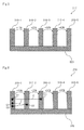
Fig. 5 is a schematic diagram describing an example of the operation of the input device shown inFig. 1 . -
Fig. 6 is a schematic diagram showing an example of the movement of the contact point between the touch panel and the input means shown inFig. 1 . -
Fig. 7 is a schematic diagram describing another example of the operation of the input device shown inFig. 1 . -
Fig. 8 is a schematic diagram showing another example of the movement of the touch point between the touch panel and the input means shown inFig. 1 . -
Fig. 9 is a schematic diagram describing a further example of the operation of the input device shown inFig. 1 . -
Fig. 10 is a schematic diagram showing another example of the structure of the friction area shown inFig. 3 . - In the following, an exemplary embodiment for carrying out the present invention will be described with reference to the drawings.
-
Fig. 1 is a block diagram showing the structure ofinput device 100 according to an embodiment of the present invention.Input device 100 is applied to information processing devices which have a touch panel, such as mobile phones, smartphones, personal computers, and portable game machines. -
Input device 100 shown inFig. 1 hastouch panel 110,storage section 120, andcontrol section 130. -
Touch panel 110 detects contact by an input means and outputs a signal corresponding to the position of the contact point of the input means to controlsection 130. As shown inFig. 2 ,touch panel 110 hasinput region 200 that detects contact by the input means. Ininput region 200,friction area 210 having a higher friction coefficient than the other areas ofinput region 200 is formed. The friction coefficient offriction area 210 is sufficiently high to allow the user to adequately sense any friction force when the user performs a slide operation or the like onfriction area 210. -
Storage section 120 stores processing amounts corresponding to the amounts by which the contact point moved onfriction area 210. - If the position of the contact point represented by the signal that is output from
touch panel 110 is moved onfriction area 210,control section 130 performs a process corresponding to a processing amount stored instorage section 120 corresponding to the amount by which the contact point moved. Information pertaining to the positions offriction area 210 has been stored, for example, instorage section 120.Control section 130 determines whether or not the position of the contact point represented by the signal that is output fromtouch panel 110 is onfriction area 210 based on the information stored instorage section 120. If the position of the contact point represented by the signal that is output fromtouch panel 110 is outside offriction area 210,control section 130 performs a process corresponding to the position of the contact point. -
Fig. 3 is an upper view showing the structure offriction area 210. - As shown in
Fig. 3 ,vertical stripe area 310 is formed asfriction area 210 in a pattern of stripes along a predetermined direction. In addition,horizontal stripe area 320 is formed such that it extends in a predetermined direction.Vertical stripe area 310 andhorizontal stripe area 320 are formed such that their friction coefficients are different from those of the other areas ofinput region 200. In other words,vertical stripe area 310 andhorizontal stripe area 320 are formed such that they have high friction coefficients that are sufficient to allow the user to adequately sense a friction force when the user performs a slide operation or the like onvertical stripe area 310 andhorizontal stripe area 320. - Next, an example of the operation of
input device 100 according to this embodiment will be described. In the following, it is assumed that the sound volume is adjusted oninput device 100. -
Storage section 120 stores processing amounts corresponding to the vertical stripes ofvertical stripe area 310 as processing amounts corresponding to the amounts by which the contact point moved onfriction area 210. According to this embodiment,storage section 120 stores processing amounts corresponding to the amounts by which the contact point moved such that when the contact point is moved for one vertical stripe ofvertical stripe area 310, the sound volume is increased or decreased by 10 % of the maximum value. - In addition,
storage section 120 stores a processing amount corresponding to a predetermined amount by which the contact point moved onhorizontal stripe area 320. According to this embodiment,storage section 120 stores the processing amount corresponding to the predetermined amount by which the contact point moved onhorizontal stripe area 320 such that the processing amount is smaller than that on other thanfriction area 210 ofinput region 200. -
Fig. 4 is a schematic diagram showing the movement of the contact point. - As shown by arrow A, it is assumed that a slide operation that moves the contact point from start point A1 to end point A2 has been performed.
-
Control section 130 counts the number of vertical stripes through which the contact point has passed based on the movement of the position of the contact point represented by the signal that is output fromtouch panel 110. As shown by arrow A, the contact point has passed rightward through four vertical stripes. As a result,control section 130 determines a processing amount by multiplying the processing amount corresponding to the amount by which the contact point moved for one vertical stripe (the processing amount for which the sound volume is increased by 10 % of the maximum value) by four, and increases the sound volume corresponding to the determined processing amount (the processing amount for which the sound volume is increased by 40 % of the maximum value). According to this embodiment, it is assumed that when the contact point is moved rightward, the sound volume is increased and that when the contact point is moved leftward, the sound volume is decreased. - As described above,
vertical stripe area 310 is formed such that it has a high friction coefficient that is sufficient to allow the user to sense a friction force when the user performs a slide operation onvertical stripe area 310. Thus, whenever the input means passes throughvertical stripe area 310, the user can sense that the input means has passed throughvertical stripe area 310, and accurately adjust the processing amount corresponding to the number of vertical stripes ofvertical stripe area 310 through which the input means has passed. - Next, as shown by arrow B, it is assumed that a slide operation that moves the contact point from start point B1 to end point B2 on
horizontal stripe area 320 has been performed. -
Control section 130 identifies the amount by which the contact point moved onhorizontal stripe area 320 based on the movement of the position of the contact point represented by the signal that is output fromtouch panel 110. Thereafter,control section 130 determines the processing amount based on the processing amount stored instorage section 120 corresponding to the predetermined amount by which the contact point moved onhorizontal stripe area 320 and identified moving amount of the contact point, and increases the sound volume corresponding to the determined processing amount. - As described above,
horizontal stripe area 320 is formed such that it has a high friction coefficient that is sufficient to allow the user to sense a friction force when the user performs a slide operation onhorizontal stripe area 320. Thus, the user can sense that the user is performing a slide operation onhorizontal stripe area 320. The processing amount corresponding to the predetermined amount by which the contact point moved onhorizontal stripe area 320 is smaller than that on other thanfriction area 210 ofinput region 200. Thus, when the user performs a slide operation onhorizontal stripe area 320, the user can finely adjust the processing amount. - Next, another example of the operation of
input device 100 will be described. - According to this embodiment, as shown in
Fig. 5 ,storage section 120 stores processing amounts corresponding to the amount by which the contact point has moved from vertical stripe 310-1 to vertical stripe 310-5 such that when the contact point is moved from vertical stripe 310-1 to vertical stripe 310-2, the sound volume is increased by 10 % of the maximum value; when the contact point is moved from vertical stripe 310-2 to vertical stripe 310-3, the sound volume is increased by 20 % of the maximum value; when the contact point is moved from vertical stripe 310-3 to vertical stripe 310-4, the sound volume is increased by 30 % of the maximum value; and when the contact point is moved from vertical stripe 310-4 to vertical stripe 310-5, the sound volume is increased by 40 % of the maximum value. In other words, the processing amount corresponding to each vertical stripe increases as the contact point is moved rightward from vertical stripe 310-1 to vertical stripe 310-5. -
Fig. 6 is a schematic diagram showing the movement of the contact point. - As shown by arrow C, it is assumed that a slide operation that moves the contact point from start point C1 on vertical stripe 310-1 to end point C2 on vertical stripe 310-3 has been performed.
-
Control section 130 identifies that the contact point has been moved from vertical stripe 310-1 to vertical stripe 310-3 based on the movement of the position of the contact point represented by the signal that is output fromtouch panel 110, determines the processing amount by adding the processing amount corresponding to the amounts by which the contact point has moved from vertical stripe 310-1 to vertical stripe 310-2 (the processing amount for which the sound volume is increased by 10 % of the maximum value) stored instorage section 120 and the processing amount corresponding to the movement of the contact point from vertical stripe 310-2 to vertical stripe 310-3 (the processing amount for which the sound volume is increased by 20 % of the maximum value) stored instorage section 120, and increases the sound volume corresponding to the determined processing amount (the processing amount for which the sound volume is increased by 30 % of the maximum value). - Next, as shown by arrow D, it is assumed that a slide operation that moves the contact point from start point D1 on vertical stripe 310-1 to point D2 on vertical stripe 310-2 and then moves the contact point to end point D3 on vertical stripe 310-1 has been performed.
-
Control section 130 identifies that the contact point has made a round trip between vertical stripe 310-1 and vertical stripe 310-2 one time based on the movement of the position of the contact point represented by the signal that is output fromtouch panel 110, determines the processing amount by multiplying the processing amount corresponding to the amount by which the contact point has moved from vertical stripe 310-1 to vertical stripe 310-2 (the processing amount for which the sound volume is increased by 10 % of the maximum value) by two, and then increases the sound volume corresponding to the determined processing amount (the processing amount for which the sound volume is increased by 20 % of the maximum value). In other words,control section 130 determines the processing amount by multiplying the processing amount corresponding to the amount by which the contact point has moved from vertical stripe 310-1 to vertical stripe 310-2 (the processing amount for which the sound volume is increased by 10 % of the maximum value) by the number of times the contact point has moved between vertical stripe 310-1 and vertical stripe 310-2. Thus, the processing amount can be increased by an increments of 10 %. - Next, another example of the operation of
input device 100 will be described. - According to this embodiment, as shown in
Fig. 7 ,storage section 120 stores processing amounts corresponding to the amount by which the contact point has moved from vertical stripe 310-5 to vertical stripe 310-1 such that when the contact point is moved from vertical stripe 310-5 to vertical stripe 310-4, the sound volume is decreased by 10 % of the maximum value; when the contact point is moved from vertical stripe 310-4 to vertical stripe 310-3, the sound volume is decreased by 20 % of the maximum value; when the contact point is moved from vertical stripe 310-3 to vertical stripe 310-2, the sound volume is decreased by 30 % of the maximum value; and when the contact point is moved from vertical stripe 310-2 to vertical stripe 310-1, the sound volume is decreased by 40 % of the maximum value. In other words, the processing amount corresponding to each vertical stripe increases as the contact point is moved leftward from vertical stripe 310-5 to vertical stripe 310-1. -
Fig. 8 is a schematic diagram showing the movement of the contact point. - As shown by arrow E, it is assumed that a slide operation that moves the contact point from start point C1 on vertical stripe 310-5 to end point C2 on vertical stripe 310-3 has been performed.
-
Control section 130 identifies that the contact point has been moved from vertical stripe 310-5 to vertical stripe 310-3 based on the movement of the position of the contact point represented by the signal that is output fromtouch panel 110, determines the processing amount by adding the processing amount corresponding to the amounts by which the contact point has moved from vertical stripe 310-5 to vertical stripe 310-4 (the processing amount for which the sound volume is decreased by 10 % of the maximum value) and the processing amount corresponding to the movement of the touch point from vertical stripe 310-4 to vertical stripe 310-3 (the processing amount for which the sound volume is decreased by 20 % of the maximum value), and decreases the sound volume corresponding to the determined processing amount (the processing amount for which the sound volume is decreased by 30 % of the maximum value). - Next, as shown by arrow F, it is assumed that a slide operation that moves the contact point from start point F1 on vertical stripe 310-5 to point F2 on vertical stripe 310-4 and then moves the contact point to end point F3 on vertical stripe 310-5 has been performed.
-
Control section 130 identifies that the contact point has made a round trip between vertical stripe 310-5 and vertical stripe 310-4 one time based on the movement of the position of the contact point represented by the signal that is output fromtouch panel 110, determines the processing amount by multiplying the processing amount corresponding to the movement of the contact point from vertical strip 310-5 to vertical strip 310-4 (the processing amount for which the sound volume is decreased by 10 % of the maximum value) by two, and then decreases the sound volume corresponding to the determined processing amount (the processing amount for which the sound volume is decreased by 20 % of the maximum value). In other words,control section 130 determines the processing amount by multiplying the processing amount corresponding to the movement of the contact point from vertical stripe 310-5 to vertical stripe 310-4 (the processing amount for which the sound volume is decreased by 10 % of the maximum value) by the number of times the contact point has been moved between vertical stripe 310-5 and vertical stripe 310-4. Thus, the processing amount can be decreased by an increments of 10%. - Next, a further example of the operation of
input device 100 will be described. - As shown in
Fig. 9 , it is assumed that vertical stripe 310-3 is touched with an input means. -
Control section 130 causesstorage section 120 to store a processing amount corresponding to the amount by which the contact point has moved from vertical stripe 310-3 to vertical stripe 310-4 such that when the contact point is moved from vertical stripe 310-3 to vertical stripe 310-4, the sound volume is increased by 10 % of the maximum value; a processing amount corresponding to the amount by which the contact point has moved from vertical stripe 310-4 to vertical stripe 310-5 such that when the contact point is moved from vertical stripe 310-4 to vertical stripe 310-5, the sound volume is increased by 20 % of the maximum value; a processing amount corresponding to the amount by which the contact point has moved from vertical stripe 310-3 to vertical stripe 310-2 such that when the contact point is moved from vertical stripe 310-3 to vertical stripe 310-2, the sound volume is decreased by 10 % of the maximum value; and a processing amount corresponding to the amount by which the contact point has moved from vertical stripe 310-2 to vertical stripe 310-1 such that when the contact point is moved from vertical stripe 310-2 to vertical stripe 310-1, the sound volume is decreased by 20 % of the maximum value. In other words, the processing amount corresponding to each vertical stripe increases rightward and leftward from vertical stripe 310-3. - Thereafter, when a slide operation that moves the contact point leftward or rightward from vertical stripe 310-3,
control section 130 determines the processing amount corresponding to the amount by which the contact point has moved and increases or decreases the sound volume corresponding to the determined processing amount. - In the foregoing examples of the operation, the sound volume is adjusted. It should be noted that the present invention is not limited to such examples. In other words, the present invention can be applied to adjustments for reduction and magnification ratios of images displayed on the touch panel and for the amount by which the cursor has moved.
- As described above, according to this embodiment,
input device 100 hastouch panel 110.Touch panel 110 hasinput region 200 in whichfriction area 210 that has a higher friction coefficient than the other areas is formed. Processing amounts corresponding to tha amount by which the contact point has moved onfriction area 210 are stored. When the position of the contact point represented by the signal that is output fromtouch panel 110 is moved onfriction area 210, a process corresponding to the stored processing amount corresponding to the amount by which the contact point has moved is performed. - Since
friction area 210 is formed such that it has a friction coefficient that is sufficient to allow the user to adequately sense a friction force onfriction area 210 with an input means, the processing amount can be more accurately or more finely adjusted since the user senses the friction force onfriction area 210 with the input means. Thus, the usability of the operation and input forinput device 100 performed through the touch panel can be improved. - Moreover, in
input device 100 according to this embodiment, the processing amount corresponding to the amount by which the contact point has moved onfriction area 210 is smaller than that on other areas ofinput region 200. - Thus, when the contact point is moved on
friction area 210, the processing amount can be more finely adjusted. As a result, the usability of the operation and input forinput device 100 performed through the touch panel can be improved. - According to this embodiment, the friction coefficient of
friction area 210 is greater than that of the other areas ofinput region 200. However, the present invention is not limited to such an example. Instead, the friction coefficient offriction area 210 may be smaller than that of the other areas ofinput region 200. - The structure of
friction area 210 is not limited to that shown inFig. 3 . For example, eithervertical stripe area 310 orhorizontal stripe area 320 may be formed. Alternatively, as shown inFig. 10 ,concentric circle area 330 may be formed asfriction area 210. - According to this embodiment, when a slide operation that moves the contact point through
vertical stripe area 310 is performed, the processing amount is determined corresponding to the number of vertical stripes through which the contact point passes. However, the present invention is not limited to such an example. Alternatively, if the foregoing slide operation is performed whilehorizontal stripe area 320 is touched with the input means, the processing amount corresponding to the number of horizontal stripes through which the contact point passes may be decided. In contrast, if the foregoing slide operation is performed whilehorizontal stripe area 320 is not touched with the input means, the same process by which the contact point is moved on other areas offriction area 210 may be performed. - According to this embodiment,
friction area 210 is located at one position ofinput region 200. Alternatively,friction area 210 may be located at a plurality of positions. - In addition, the friction coefficient of
friction area 210 may not be uniform. - According to this embodiment,
touch panel 110 hasinput region 200 in whichfriction area 210 that detects contact by an input means is formed. However, the present invention is not limited to such an example. Alternatively,touch panel 110 may detect the neighbor of an input means. For example,touch panel 110 may be formed such that a transparent panel is located oninput region 200 and a friction area is located on the transparent panel. In this case,control section 130 acquires information about the position of the friction area on the panel through an external storage medium, an external network, or the like and determines if the position of the contact point represented by a signal that is output fromtouch panel 110 is on the friction area of the panel. If the position of the contact point is on the friction area of the panel, the processes for the foregoing examples of the operation are performed. As a result, various panels that correspond can be used corresponding to applications executed oninput device 100 can be used. - A method for the input device according to the present invention may be applied to a program executed on a computer. In addition, the program can be stored on a storage medium and can be provided to the outside through a network.
- The present invention has been described with reference to the embodiments. However, it should be understood by those skilled in the art that the structure and details of the present invention may be changed in various manners without departing from the scope of the present invention.
- The present application claims priority based on Japanese Patent Application
JP 2011-124275 filed on June 2, 2011
Claims (7)
- An input device, comprising:a touch panel that has an input region that detects contact by input means, said input region having a friction area, a friction coefficient of said friction area being different from that of other areas of said input region, and outputs a signal corresponding to a position of a contact point of said input means;a storage section that stores processing amounts corresponding to the amounts by which said contact point has moved on said friction area; anda control section that performs a process corresponding to a processing amount stored in said storage section corresponding to an amount by which the contact point has moved, when the position of said contact point represented by a signal that is output from said touch panel has been moved on said friction area.
- The input device according to claim 1,
wherein said friction area is formed in a pattern of stripes,
wherein said storage section stores processing amounts corresponding to stripes of said friction area, and
wherein, when the position of said contact point represented by the signal that is output from said touch panel has been moved on said friction area, said control section identifies the number of stripes for which said contact point has been moved; determines a processing amount based on the identified number of stripes for which said contact point has been moved and the processing amount corresponding to stripes of said friction area, and performs a process corresponding to the determined processing amount. - The input device according to claim 1,
wherein said friction area is formed such that it extends in a predetermined direction,
wherein said storage section stores a processing amount corresponding to a predetermined amount by which said contact point has moved on said friction area, and
wherein, when the position of said contact point represented by the signal that is output from said touch panel has moved on said friction area, said control section identifies the amount by which said contact point has moved on said friction area, determines a processing amount based on the identified moving amount and the processing amount corresponding to the predetermined amount by which said contact point, in said storage section, has moved, and performs a process corresponding to the determined processing amount. - A control method of an input device having a touch panel that detects contact by input means and that outputs a signal corresponding to a position of a contact point of said input means, includes:storing processing amounts corresponding to amounts by which said contact point has moved on a friction area formed in an input region that detects contact by said input means, a friction coefficient of said friction area being different from that of other areas of said input region; andwhen the position of said contact point represented by the signal that is output from said touch panel has been moved on said friction area, performing a process corresponding to a stored processing amount that corresponds to an amount by which said contact point has moved.
- The control method of the input device according to claim 4,
wherein said storing step is performed by storing processing amounts corresponding to stripes of said friction area, and
wherein said determining step is performed by determining if the position of said contact point represented by the signal that is output from said touch panel has been moved, and if so, deciding the number of stripes for which said contact point has moved, acquiring a processing amount stored corresponding to the number of stripes, and performing a process corresponding to the acquired processing amount. - The control method of the input device according to claim 4,
wherein said storing step is performed by storing a processing amount corresponding to a predetermined amount by which said contact point has moved on said friction area formed such that it extends in a predetermined direction, and
wherein said determining step is performed by determining if the position of said contact point represented by the signal that is output from said touch panel has been moved, and if so, identifying the amount by which said contact point has moved on said friction area, acquiring a processing amount based on the decided moving amount and the processing amount stored corresponding to the predetermined amount by which said contact point has moved, and performing a process corresponding to the acquired processing amount. - A program that causes an input device having a touch panel that detects contact by input means and that outputs a signal corresponding to a position of a contact point of said input means to execute processes includes:storing processing amounts corresponding to amounts by which said contact point has moved on a friction area formed in an input region that detects contact by said input means, a friction coefficient of said friction area being different from that of other areas of said input region; andwhen the position of said contact point represented by the signal that is output from said touch panel has been moved on said friction area, performing a process corresponding to a stored processing amount that corresponds to an amount by which the contact point has moved.
Applications Claiming Priority (2)
| Application Number | Priority Date | Filing Date | Title |
|---|---|---|---|
| JP2011124275 | 2011-06-02 | ||
| PCT/JP2012/061605 WO2012165098A1 (en) | 2011-06-02 | 2012-05-02 | Input device, input device control method, and program |
Publications (1)
| Publication Number | Publication Date |
|---|---|
| EP2717130A1 true EP2717130A1 (en) | 2014-04-09 |
Family
ID=47258962
Family Applications (1)
| Application Number | Title | Priority Date | Filing Date |
|---|---|---|---|
| EP12794151.6A Withdrawn EP2717130A1 (en) | 2011-06-02 | 2012-05-02 | Input device, input device control method, and program |
Country Status (4)
| Country | Link |
|---|---|
| US (1) | US20140111455A1 (en) |
| EP (1) | EP2717130A1 (en) |
| JP (1) | JPWO2012165098A1 (en) |
| WO (1) | WO2012165098A1 (en) |
Families Citing this family (2)
| Publication number | Priority date | Publication date | Assignee | Title |
|---|---|---|---|---|
| US10592006B2 (en) * | 2017-01-13 | 2020-03-17 | Microsoft Technology Licensing, Llc | Pattern for increased coefficient of friction of input devices |
| EP4653992A4 (en) * | 2023-10-27 | 2026-07-08 | Shenzhen Shokz Co Ltd | DEVICE FOR USING A FRICTION SIGNAL TO IDENTIFY A CONTACT OPERATION |
Family Cites Families (7)
| Publication number | Priority date | Publication date | Assignee | Title |
|---|---|---|---|---|
| JPH0575837U (en) | 1992-03-16 | 1993-10-15 | 横河電機株式会社 | Touch screen input device |
| JPH0830369A (en) * | 1994-07-15 | 1996-02-02 | Oki Electric Ind Co Ltd | Coordinate input device |
| WO1999044117A1 (en) * | 1998-02-25 | 1999-09-02 | Sharp Kabushiki Kaisha | Display device |
| JP2005056180A (en) * | 2003-08-05 | 2005-03-03 | Tokai Rika Co Ltd | Input device |
| US20100315345A1 (en) * | 2006-09-27 | 2010-12-16 | Nokia Corporation | Tactile Touch Screen |
| JP4561888B2 (en) * | 2008-07-01 | 2010-10-13 | ソニー株式会社 | Information processing apparatus and vibration control method in information processing apparatus |
| JP4875050B2 (en) * | 2008-12-09 | 2012-02-15 | 京セラ株式会社 | Input device |
-
2012
- 2012-05-02 EP EP12794151.6A patent/EP2717130A1/en not_active Withdrawn
- 2012-05-02 JP JP2013517936A patent/JPWO2012165098A1/en active Pending
- 2012-05-02 US US14/122,581 patent/US20140111455A1/en not_active Abandoned
- 2012-05-02 WO PCT/JP2012/061605 patent/WO2012165098A1/en not_active Ceased
Non-Patent Citations (1)
| Title |
|---|
| See references of WO2012165098A1 * |
Also Published As
| Publication number | Publication date |
|---|---|
| WO2012165098A1 (en) | 2012-12-06 |
| JPWO2012165098A1 (en) | 2015-02-23 |
| US20140111455A1 (en) | 2014-04-24 |
Similar Documents
| Publication | Publication Date | Title |
|---|---|---|
| US10437360B2 (en) | Method and apparatus for moving contents in terminal | |
| KR102027555B1 (en) | Method for displaying contents and an electronic device thereof | |
| US9035883B2 (en) | Systems and methods for modifying virtual keyboards on a user interface | |
| US20150116230A1 (en) | Display Device and Icon Control Method Thereof | |
| US20120278754A1 (en) | Elastic Over-Scroll | |
| KR20140128146A (en) | Method for displaying and an electronic device thereof | |
| US20140210742A1 (en) | Emulating pressure sensitivity on multi-touch devices | |
| US9489069B2 (en) | Method for controlling display scrolling and zooming and an electronic device thereof | |
| US20150261408A1 (en) | Multi-stage Cursor Control | |
| US20160239177A1 (en) | Display control apparatus, control method therefor, and storage medium storing control program therefor | |
| KR20150071130A (en) | Method and apparatus for controlling scroll in portable device | |
| US20140164993A1 (en) | Method and electronic device for enlarging and displaying contents | |
| EP2693324A2 (en) | Method and apparatus for controlling drag for a moving object of a mobile terminal having a touch screen | |
| KR102096070B1 (en) | Method for improving touch recognition and an electronic device thereof | |
| EP2767897B1 (en) | Method for generating writing data and an electronic device thereof | |
| EP3229132A1 (en) | Method and system for detection and resolution of frustration with a device user interface | |
| KR102135947B1 (en) | Method for resizing window area and electronic device for the same | |
| KR102274156B1 (en) | Method for resizing window area and electronic device for the same | |
| CN104978135A (en) | Icon display method and device, and mobile terminal | |
| JP6411067B2 (en) | Information processing apparatus and input method | |
| US9547433B1 (en) | Systems and methods for changing control functions during an input gesture | |
| US20140111455A1 (en) | Input device, control method thereof, and program | |
| CN103870175B (en) | Display method and electronic device | |
| US20140317568A1 (en) | Information processing apparatus, information processing method, program, and information processing system | |
| CN105247464A (en) | Display control device and its control method and program |
Legal Events
| Date | Code | Title | Description |
|---|---|---|---|
| PUAI | Public reference made under article 153(3) epc to a published international application that has entered the european phase |
Free format text: ORIGINAL CODE: 0009012 |
|
| 17P | Request for examination filed |
Effective date: 20131204 |
|
| AK | Designated contracting states |
Kind code of ref document: A1 Designated state(s): AL AT BE BG CH CY CZ DE DK EE ES FI FR GB GR HR HU IE IS IT LI LT LU LV MC MK MT NL NO PL PT RO RS SE SI SK SM TR |
|
| STAA | Information on the status of an ep patent application or granted ep patent |
Free format text: STATUS: THE APPLICATION HAS BEEN WITHDRAWN |
|
| 18W | Application withdrawn |
Effective date: 20140415 |