EP2716982A2 - Air conditioner outdoor unit - Google Patents
Air conditioner outdoor unit Download PDFInfo
- Publication number
- EP2716982A2 EP2716982A2 EP13186989.3A EP13186989A EP2716982A2 EP 2716982 A2 EP2716982 A2 EP 2716982A2 EP 13186989 A EP13186989 A EP 13186989A EP 2716982 A2 EP2716982 A2 EP 2716982A2
- Authority
- EP
- European Patent Office
- Prior art keywords
- operating
- flange portion
- valve bracket
- dish
- valve
- Prior art date
- Legal status (The legal status is an assumption and is not a legal conclusion. Google has not performed a legal analysis and makes no representation as to the accuracy of the status listed.)
- Withdrawn
Links
- 230000005494 condensation Effects 0.000 description 45
- 238000009833 condensation Methods 0.000 description 45
- XLYOFNOQVPJJNP-UHFFFAOYSA-N water Substances O XLYOFNOQVPJJNP-UHFFFAOYSA-N 0.000 description 32
- 239000003507 refrigerant Substances 0.000 description 8
- 239000003657 drainage water Substances 0.000 description 3
- 229910000831 Steel Inorganic materials 0.000 description 2
- 238000007664 blowing Methods 0.000 description 2
- 230000000694 effects Effects 0.000 description 2
- 238000009434 installation Methods 0.000 description 2
- 238000011084 recovery Methods 0.000 description 2
- 239000010959 steel Substances 0.000 description 2
- 238000012986 modification Methods 0.000 description 1
- 230000004048 modification Effects 0.000 description 1
- 238000005192 partition Methods 0.000 description 1
- 238000003466 welding Methods 0.000 description 1
Images



Classifications
-
- F—MECHANICAL ENGINEERING; LIGHTING; HEATING; WEAPONS; BLASTING
- F24—HEATING; RANGES; VENTILATING
- F24F—AIR-CONDITIONING; AIR-HUMIDIFICATION; VENTILATION; USE OF AIR CURRENTS FOR SCREENING
- F24F1/00—Room units for air-conditioning, e.g. separate or self-contained units or units receiving primary air from a central station
- F24F1/06—Separate outdoor units, e.g. outdoor unit to be linked to a separate room comprising a compressor and a heat exchanger
- F24F1/26—Refrigerant piping
- F24F1/32—Refrigerant piping for connecting the separate outdoor units to indoor units
-
- F—MECHANICAL ENGINEERING; LIGHTING; HEATING; WEAPONS; BLASTING
- F24—HEATING; RANGES; VENTILATING
- F24F—AIR-CONDITIONING; AIR-HUMIDIFICATION; VENTILATION; USE OF AIR CURRENTS FOR SCREENING
- F24F1/00—Room units for air-conditioning, e.g. separate or self-contained units or units receiving primary air from a central station
- F24F1/06—Separate outdoor units, e.g. outdoor unit to be linked to a separate room comprising a compressor and a heat exchanger
- F24F1/26—Refrigerant piping
- F24F1/34—Protection means thereof, e.g. covers for refrigerant pipes
-
- F—MECHANICAL ENGINEERING; LIGHTING; HEATING; WEAPONS; BLASTING
- F24—HEATING; RANGES; VENTILATING
- F24F—AIR-CONDITIONING; AIR-HUMIDIFICATION; VENTILATION; USE OF AIR CURRENTS FOR SCREENING
- F24F1/00—Room units for air-conditioning, e.g. separate or self-contained units or units receiving primary air from a central station
- F24F1/06—Separate outdoor units, e.g. outdoor unit to be linked to a separate room comprising a compressor and a heat exchanger
- F24F1/42—Separate outdoor units, e.g. outdoor unit to be linked to a separate room comprising a compressor and a heat exchanger characterised by the use of the condensate, e.g. for enhanced cooling
-
- F—MECHANICAL ENGINEERING; LIGHTING; HEATING; WEAPONS; BLASTING
- F24—HEATING; RANGES; VENTILATING
- F24F—AIR-CONDITIONING; AIR-HUMIDIFICATION; VENTILATION; USE OF AIR CURRENTS FOR SCREENING
- F24F1/00—Room units for air-conditioning, e.g. separate or self-contained units or units receiving primary air from a central station
- F24F1/06—Separate outdoor units, e.g. outdoor unit to be linked to a separate room comprising a compressor and a heat exchanger
- F24F1/56—Casing or covers of separate outdoor units, e.g. fan guards
-
- F—MECHANICAL ENGINEERING; LIGHTING; HEATING; WEAPONS; BLASTING
- F24—HEATING; RANGES; VENTILATING
- F24F—AIR-CONDITIONING; AIR-HUMIDIFICATION; VENTILATION; USE OF AIR CURRENTS FOR SCREENING
- F24F13/00—Details common to, or for air-conditioning, air-humidification, ventilation or use of air currents for screening
- F24F13/22—Means for preventing condensation or evacuating condensate
- F24F13/222—Means for preventing condensation or evacuating condensate for evacuating condensate
Definitions
- the present invention relates to an air conditioner outdoor unit in which an operating-valve bracket is installed on a baseplate of the outdoor unit.
- an operating-valve bracket that is provided with operating valves to which refrigerant pipes are connected is installed inside a machine chamber in the outdoor unit so as to be exposed to the outside from a side panel.
- this operating-valve bracket is fixed to a flange portion that is provided on the periphery of a baseplate of the outdoor unit so as to extend vertically upward.
- the operating-valve bracket is installed such that the operating valves are exposed to the outside from the side panel.
- two valves are vertically arranged in a slanted direction, and a gas-side refrigerant pipe and a liquid-side refrigerant pipe that are connected to an indoor unit can be connected to these operating valves.
- the operating valves and the outer surface of the operating-valve bracket are covered with a service cover (also referred to as side cover) that is detachably attached to a side panel of the outdoor unit.
- the gas-side operating valve and the liquid-side operating valve are provided on the operating-valve bracket.
- the operating-valve bracket When a low-pressure refrigerant is circulated through the operating valves, the operating-valve bracket is cooled together with the operating valves, and dew condensation water is produced on the surfaces thereof.
- the dew condensation water flows downward along the surface of the operating-valve bracket and, in some cases, splashes or leaks out from a portion where the operating-valve bracket is installed to the outside of the baseplate beyond the flange portion provided at the periphery of the base plate, whereas the dew condensation water flowing downward should normally be recovered in the baseplate with the flange portion which extends upward at the periphery thereof.
- the present invention has been made in view of such circumstances, and an object thereof is to provide an air conditioner outdoor unit capable of reliably recovering, in the baseplate, dew condensation water that is produced through dew condensation on the surfaces of the operating-valve bracket and on the operating valves and that flows downward on the surfaces.
- the air conditioner outdoor unit of the present invention employs the following solutions.
- the present invention provides an air conditioner outdoor unit in which a flange portion is provided on a periphery of a baseplate so as to extend vertically upward from the periphery, and an operating-valve bracket is fixedly attached to the flange portion, the air conditioner outdoor unit comprising a pair of dish-shaped projection portions provided on one of a side surface of the operating-valve bracket at fastening sites which are fixed to the flange portion and a side surface of the flange portion at fastening sites which are fixed to the operating-valve bracket so that the dish-shaped projection portions project toward the side surface of the other by a certain dimension, the pair of dish-shaped projection portions having a predetermined distance therebetween, wherein the operating-valve bracket is fixed to the flange portion such that a space is formed between the side surface of the operating-valve bracket and the side surface of the flange
- the pair of dish-shaped projection portions having the predetermined space therebetween, are provided on one of the side surface of the operating-valve bracket at fastening sites which are to be fixed to the flange portion and the side surface of the flange portion at fastening sites which are to be fixed to the operating-valve bracket, so as to project toward the side surface of the other by a fixed dimension, and the operating-valve bracket is fixed to the flange portion such that the certain space is formed between the side surface of the operating-valve bracket and the side surface of the flange portion by the dish-shaped projection portions.
- the operating-valve bracket can be fixed to the flange portion on the periphery of the baseplate, such that a space corresponding to the projection dimension of the dish-shaped projection portions is formed between the side surface of the flange portion on the periphery of the baseplate and the side surface of the operating-valve bracket, which is fixed to the flange portion. Then, dew condensation water that is produced through dew condensation occurring on the surface of the operating-valve bracket when the operating-valve bracket is cooled by the operating valves and that drips down can be recovered in the baseplate via that space.
- the dew condensation water produced through dew condensation on the surface of the operating-valve bracket can be reliably recovered in the baseplate and discharged, thus making it possible to prevent a situation in which the dew condensation water splashes or leaks out to the outside from the side surface on which the operating valves are provided.
- the pair of dish-shaped projection portions are provided at lower portions on an outer surface of the operating-valve bracket so as to have the predetermined distance therebetween.
- the pair of dish-shaped projection portions having a predetermined distance therebetween, are provided at lower portions on the outer surface of the operating-valve bracket.
- dew condensation water produced through dew condensation on the surface of the operating-valve bracket can be recovered in the baseplate via the space, thus making it possible to reliably prevent the dew condensation water from splashing or leaking out to the outside from the side surface on which the operating valves are provided.
- a portion of the flange portion between the pair of fastening sites at which the operating-valve bracket is fastened bulges outward by a certain dimension.
- a portion of the flange portion between the pair of fastening sites at which the operating-valve bracket is fastened bulges outward by the certain dimension.
- the space formed between the side surface of the flange portion and the side surface of the operating-valve bracket can be made to correspond to the sum of the projection dimension of the dish-shaped projection portions and the outward-bulging dimension of the flange portion. Therefore, the space for guiding dew condensation water produced through dew condensation on the surface of the operating-valve bracket to the inside of the baseplate can be made even larger, thus facilitating the recovery of the dew condensation water in the baseplate.
- the pair of dish-shaped projection portions are provided on an inner surface of the flange portion so as to have the predetermined distance therebetween.
- the pair of dish-shaped projection portions having the predetermined distance therebetween, are provided on the inner surface of the flange portion.
- the pair of dish-shaped projection portions are provided at the fastening sites on the flange portion so as to project from the inner surface thereof toward the operating-valve bracket by the certain dimension, and the operating-valve bracket is fixed to the flange portion via the dish-shaped projection portions, thereby making it possible to form a space corresponding to the projection dimension of the dish-shaped projection portions, between the side surfaces of the flange portion and the operating-valve bracket.
- dew condensation water produced through dew condensation on the surface of the operating-valve bracket can be recovered in the baseplate via the space, and the dew condensation water can be reliably prevented from splashing or leaking out to the outside of the side surface on which the operating valves are provided.
- the present invention it is possible to fix the operating-valve bracket to the flange portion on the periphery of the baseplate, forming a space corresponding to the projection dimension of the dish-shaped projection portions, between the side surface of the flange portion on the periphery of the baseplate and the side surface of the operating-valve bracket fixed to the flange portion. Furthermore, dew condensation water that is produced through dew condensation occurring on the surface of the operating-valve bracket when the operating-valve bracket is cooled by operating valves and that drips down can be recovered in the baseplate via the space.
- the dew condensation water produced through dew condensation on the surface of the operating-valve bracket can be reliably recovered in the baseplate and discharged, thus making it possible to prevent a situation in which the dew condensation water splashes or leaks out to the outside from the side surface on which the operating valves are provided.
- FIG. 1 is a perspective view showing an air conditioner outdoor unit with a service panel removed from the outdoor unit according to the embodiment of the present invention.
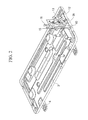
- Fig. 2 is a perspective view showing a state in which an operating-valve bracket has been installed on a baseplate.
- Fig. 3 is a perspective view of the operating-valve bracket.
- Fig. 4 is a longitudinal sectional view of an installation portion where the operating-valve bracket is installed.
- An air conditioner outdoor unit 1 has a chassis 2 comprising a baseplate 3 that is provided with a plurality of mounting legs 4 on a bottom surface thereof, a front panel 5 that is provided with an outlet grille 6 and that is installed on the baseplate 3, right and left side panels 7, 8, and a top panel 9.
- the rear side of the chassis 2 is almost wholly open, and a plate-fin-tube outdoor heat exchanger is installed in alignment with the opening.
- the inside of the chassis 2 is separated into a heat exchanger chamber and a machine chamber by a partition plate.
- the heat exchanger chamber includes the above-described outdoor heat exchanger and an air-blowing fan that makes outside air circulate through the outdoor heat exchanger and that blows it out to the front outside from the outlet grille 6.
- the machine chamber includes a compressor, a four-way switching valve, a control box, an operating-valve bracket 10, and a terminal block 11 to which a power line and a communication line are connected.
- the operating-valve bracket 10 and the terminal block 11 are installed so as to be exposed to the outside from the side panel 7, and the outer surface side thereof is covered with a service cover (also referred to as side cover) (not shown) that is detachably attached to the side panel 7 of the outdoor unit 1.
- a service cover also referred to as side cover
- the baseplate 3 of the chassis 2 is a horizontally elongated rectangular steel plate, portions for installing the outdoor heat exchanger, the air-blowing fan, and the compressor are formed thereon, and a flange portion 3A that extends vertically upward and has a predetermined height is formed on the periphery thereof.
- the operating-valve bracket 10 is fixed to a portion of the flange portion 3A located at the right side of the baseplate 3, via fastening means, such as screws.
- the operating-valve bracket 10 is a vertically elongated rectangular steel part.
- the valves are fixed to the operating-valve bracket 10 by means of screws 14 so that the operating valves 12 and 13 are vertically arranged in a slanted direction.
- the gas-side operating valve 12 and the liquid-side operating valve 13 are provided with refrigerant connection pipes 16 and 15 to be connected to components of the outdoor unit 1.
- a pair of dish-shaped projection portions 17 that are provided with a predetermined distance therebetween and that project toward the flange portion 3A by a certain dimension are formed integrally with the operating-valve bracket 10, and the projection portions are provided at fastening sites to be fixed to the flange portion 3A, which are located at right and left lower portions on the outer surface of the operating-valve bracket 10.
- the pair of dish-shaped projection portions 17 have fastening holes 18 for fastening screws.
- dew condensation water that is produced through dew condensation occurring on the surfaces of the operating-valve bracket 10, the gas-side operating valve 12, and the liquid-side operating valve 13 and that flows downward along the surface of the operating-valve bracket 10 can be recovered in the baseplate 3 via the space S.
- the outdoor unit 1 is usually located outside, even if drainage water produced in the outdoor unit 1 is directly discharged to the outside, this causes little problem.
- a discharge hole is generally provided at a specified location on the baseplate 3, and drainage water is discharged therefrom.
- the space S corresponding to the projection dimension of the dish-shaped projection portions 17, which are provided on the operating-valve bracket 10, can be formed between the side surface of the flange portion 3A on the periphery of the baseplate 3 and the side surface of the operating-valve bracket 10 to be fixed to the flange portion 3A, and the operating-valve bracket 10 can be fixed to the flange portion 3A on the periphery of the baseplate 3.
- dew condensation water that is produced through dew condensation occurring on the surface of the operating-valve bracket 10 when the operating-valve bracket 10 is cooled by the gas-side operating valve 12 and the liquid-side operating valve 13 and that drips down can be recovered in the baseplate 3 via the space S.
- dew condensation water produced through dew condensation on the surface of the operating-valve bracket 10 can be reliably recovered in the baseplate 3, thus making it possible to prevent a situation in which the dew condensation water splashes or leaks out to the outside from the side surface on which the operating valves 12, 13 are provided.
- the pair of the dish-shaped projection portions 17, having a predetermined distance therebetween, are provided at lower portions on the outer surface of the operating-valve bracket 10.
- dew condensation water produced through dew condensation on the surface of the operating-valve bracket 10 can be recovered in the baseplate 3 via the space S, and the dew condensation water can be reliably prevented from splashing or leaking out to the outside from the side surface on which the operating valves 12, 13 are provided.
- the space S corresponding to the projection dimension of the dish-shaped projection portions can be formed between the side surfaces of the flange portion 3A and the operating-valve bracket 10. Therefore, dew condensation water produced through dew condensation on the surface of the operating-valve bracket 10 can be recovered in the baseplate 3 via the space S, and the dew condensation water can be prevented from splashing or leaking out to the outside from the side surface on which the operating valves 12, 13 are provided.
- the space S formed between the side surface of the flange portion 3A and the side surface of the operating-valve bracket 10 can be made to correspond to the sum of the projection dimension of the dish-shaped projection portions 17 and the outward-bulging dimension of the flange portion 3A.
- the space S for guiding dew condensation water produced through dew condensation on the surface of the operating-valve bracket 10 to the inside of the baseplate 3 can be made even larger, thus facilitating the recovery of the dew condensation water in the baseplate 3.
- the present invention is not limited to the inventions according to the above-described embodiments and can be appropriately modified without departing from the scope of the present invention.
- the operating-valve bracket 10 is fixed to the flange portion 3A with screws, screws are not necessarily used for fixing the bracket, and, another means, for example, welding, can be used.
- the shape of the operating-valve bracket 10 and the specific structure of the gas-side operating valve 12 and the liquid-side operating valve 13 are not limited to those of the above-described embodiments, and various modifications can be adopted.
Landscapes
- Engineering & Computer Science (AREA)
- Chemical & Material Sciences (AREA)
- Combustion & Propulsion (AREA)
- Mechanical Engineering (AREA)
- General Engineering & Computer Science (AREA)
- Other Air-Conditioning Systems (AREA)
Abstract
Description
- The present invention relates to an air conditioner outdoor unit in which an operating-valve bracket is installed on a baseplate of the outdoor unit.
- In an air conditioner outdoor unit, an operating-valve bracket that is provided with operating valves to which refrigerant pipes are connected is installed inside a machine chamber in the outdoor unit so as to be exposed to the outside from a side panel. As disclosed in PTL 1, this operating-valve bracket is fixed to a flange portion that is provided on the periphery of a baseplate of the outdoor unit so as to extend vertically upward. Furthermore, in order to allow access to the operating valves from the outside, the operating-valve bracket is installed such that the operating valves are exposed to the outside from the side panel.
- As the operating valves, two valves, specifically, a gas-side operating valve and a liquid-side operating valve, are vertically arranged in a slanted direction, and a gas-side refrigerant pipe and a liquid-side refrigerant pipe that are connected to an indoor unit can be connected to these operating valves. The operating valves and the outer surface of the operating-valve bracket are covered with a service cover (also referred to as side cover) that is detachably attached to a side panel of the outdoor unit.
- {PTL 1} Japanese Unexamined Patent Application, Publication No.
H10-259932 - In the above-described outdoor unit, the gas-side operating valve and the liquid-side operating valve are provided on the operating-valve bracket. When a low-pressure refrigerant is circulated through the operating valves, the operating-valve bracket is cooled together with the operating valves, and dew condensation water is produced on the surfaces thereof. The dew condensation water flows downward along the surface of the operating-valve bracket and, in some cases, splashes or leaks out from a portion where the operating-valve bracket is installed to the outside of the baseplate beyond the flange portion provided at the periphery of the base plate, whereas the dew condensation water flowing downward should normally be recovered in the baseplate with the flange portion which extends upward at the periphery thereof.
- This occurs because the side surface of the operating-valve bracket is fixed by being fastened to the inner surface of the flange portion by means of screws, and thus the dew condensation water flowing downward on the surface of the operating-valve bracket flows out beyond the flange portion. When a large quantity of dew condensation water is produced, the quantity of dew condensation water splashing or leaking out is increased, which may lead to trouble depending on how or where the outdoor unit is installed.
- The present invention has been made in view of such circumstances, and an object thereof is to provide an air conditioner outdoor unit capable of reliably recovering, in the baseplate, dew condensation water that is produced through dew condensation on the surfaces of the operating-valve bracket and on the operating valves and that flows downward on the surfaces.
- In order to make an improvement in the abovementined circumstances, the air conditioner outdoor unit of the present invention employs the following solutions.
Specifically, according to a first aspect, the present invention provides an air conditioner outdoor unit in which a flange portion is provided on a periphery of a baseplate so as to extend vertically upward from the periphery, and an operating-valve bracket is fixedly attached to the flange portion, the air conditioner outdoor unit comprising a pair of dish-shaped projection portions provided on one of a side surface of the operating-valve bracket at fastening sites which are fixed to the flange portion and a side surface of the flange portion at fastening sites which are fixed to the operating-valve bracket so that the dish-shaped projection portions project toward the side surface of the other by a certain dimension, the pair of dish-shaped projection portions having a predetermined distance therebetween, wherein the operating-valve bracket is fixed to the flange portion such that a space is formed between the side surface of the operating-valve bracket and the side surface of the flange portion by the dish-shaped projection portions. - According to the first aspect of the present invention, in the air conditioner outdoor unit in which the operating-valve bracket is fixed to the flange portion provided on the periphery of the baseplate, the pair of dish-shaped projection portions, having the predetermined space therebetween, are provided on one of the side surface of the operating-valve bracket at fastening sites which are to be fixed to the flange portion and the side surface of the flange portion at fastening sites which are to be fixed to the operating-valve bracket, so as to project toward the side surface of the other by a fixed dimension, and the operating-valve bracket is fixed to the flange portion such that the certain space is formed between the side surface of the operating-valve bracket and the side surface of the flange portion by the dish-shaped projection portions. Thus, the operating-valve bracket can be fixed to the flange portion on the periphery of the baseplate, such that a space corresponding to the projection dimension of the dish-shaped projection portions is formed between the side surface of the flange portion on the periphery of the baseplate and the side surface of the operating-valve bracket, which is fixed to the flange portion. Then, dew condensation water that is produced through dew condensation occurring on the surface of the operating-valve bracket when the operating-valve bracket is cooled by the operating valves and that drips down can be recovered in the baseplate via that space. Therefore, the dew condensation water produced through dew condensation on the surface of the operating-valve bracket can be reliably recovered in the baseplate and discharged, thus making it possible to prevent a situation in which the dew condensation water splashes or leaks out to the outside from the side surface on which the operating valves are provided.
- Furthermore, according to a second aspect of the present invention, in the above-described air conditioner outdoor unit, the pair of dish-shaped projection portions are provided at lower portions on an outer surface of the operating-valve bracket so as to have the predetermined distance therebetween.
- According to the second aspect of the present invention, the pair of dish-shaped projection portions, having a predetermined distance therebetween, are provided at lower portions on the outer surface of the operating-valve bracket. Thus, by fixing the operating-valve bracket, which is provided with the pair of dish-shaped projection portions projecting from the outer surface thereof toward the flange portion by the certain dimension at the fastening sites which are to be fixed to the flange portion, to the flange portion via the dish-shaped projection portions, the space corresponding to the projection dimension of the dish-shaped projection portions can be formed between the side surfaces of the flange portion and the operating-valve bracket. Therefore, dew condensation water produced through dew condensation on the surface of the operating-valve bracket can be recovered in the baseplate via the space, thus making it possible to reliably prevent the dew condensation water from splashing or leaking out to the outside from the side surface on which the operating valves are provided.
- Furthermore, according to a third aspect of the present invention, in one of the above-described air conditioner outdoor units, a portion of the flange portion between the pair of fastening sites at which the operating-valve bracket is fastened bulges outward by a certain dimension.
- According to the third aspect of the present invention, a portion of the flange portion between the pair of fastening sites at which the operating-valve bracket is fastened bulges outward by the certain dimension. Thus, the space formed between the side surface of the flange portion and the side surface of the operating-valve bracket can be made to correspond to the sum of the projection dimension of the dish-shaped projection portions and the outward-bulging dimension of the flange portion. Therefore, the space for guiding dew condensation water produced through dew condensation on the surface of the operating-valve bracket to the inside of the baseplate can be made even larger, thus facilitating the recovery of the dew condensation water in the baseplate.
- Furthermore, according to a fourth aspect of the present invention, in the above-described air conditioner outdoor unit, the pair of dish-shaped projection portions are provided on an inner surface of the flange portion so as to have the predetermined distance therebetween.
- According to the fourth aspect of the present invention, the pair of dish-shaped projection portions, having the predetermined distance therebetween, are provided on the inner surface of the flange portion. Thus, the pair of dish-shaped projection portions are provided at the fastening sites on the flange portion so as to project from the inner surface thereof toward the operating-valve bracket by the certain dimension, and the operating-valve bracket is fixed to the flange portion via the dish-shaped projection portions, thereby making it possible to form a space corresponding to the projection dimension of the dish-shaped projection portions, between the side surfaces of the flange portion and the operating-valve bracket. Therefore, dew condensation water produced through dew condensation on the surface of the operating-valve bracket can be recovered in the baseplate via the space, and the dew condensation water can be reliably prevented from splashing or leaking out to the outside of the side surface on which the operating valves are provided.
- According to the present invention, it is possible to fix the operating-valve bracket to the flange portion on the periphery of the baseplate, forming a space corresponding to the projection dimension of the dish-shaped projection portions, between the side surface of the flange portion on the periphery of the baseplate and the side surface of the operating-valve bracket fixed to the flange portion. Furthermore, dew condensation water that is produced through dew condensation occurring on the surface of the operating-valve bracket when the operating-valve bracket is cooled by operating valves and that drips down can be recovered in the baseplate via the space. Thus, the dew condensation water produced through dew condensation on the surface of the operating-valve bracket can be reliably recovered in the baseplate and discharged, thus making it possible to prevent a situation in which the dew condensation water splashes or leaks out to the outside from the side surface on which the operating valves are provided.
-
- {
Fig. 1} Fig. 1 is a perspective view showing an air conditioner outdoor unit with a service panel removed from the outdoor unit according to a first embodiment of the present invention. - {
Fig. 2} Fig. 2 is a perspective view showing a state in which an operating-valve bracket has been installed on a baseplate of the outdoor unit shown inFig. 1 . - {
Fig. 3} Fig. 3 is a perspective view of the operating-valve bracket shown inFig. 2 . - {
Fig. 4} Fig. 4 is a longitudinal sectional view of an installation portion where the operating-valve bracket shown inFig. 2 is installed. - {
Fig. 5} Fig. 5 is a partial perspective view of an operating-valve bracket and a flange portion on a baseplate according to another embodiment of the present invention. - Embodiments of the present invention will be described below with reference to the drawings.
- A first embodiment of the present invention will be described below with reference to
Figs. 1 to 4 .
Fig. 1 is a perspective view showing an air conditioner outdoor unit with a service panel removed from the outdoor unit according to the embodiment of the present invention.Fig. 2 is a perspective view showing a state in which an operating-valve bracket has been installed on a baseplate.Fig. 3 is a perspective view of the operating-valve bracket.Fig. 4 is a longitudinal sectional view of an installation portion where the operating-valve bracket is installed.
An air conditioner outdoor unit 1 has achassis 2 comprising abaseplate 3 that is provided with a plurality ofmounting legs 4 on a bottom surface thereof, afront panel 5 that is provided with anoutlet grille 6 and that is installed on thebaseplate 3, right andleft side panels 7, 8, and atop panel 9. - The rear side of the
chassis 2 is almost wholly open, and a plate-fin-tube outdoor heat exchanger is installed in alignment with the opening. As is known, the inside of thechassis 2 is separated into a heat exchanger chamber and a machine chamber by a partition plate. The heat exchanger chamber includes the above-described outdoor heat exchanger and an air-blowing fan that makes outside air circulate through the outdoor heat exchanger and that blows it out to the front outside from theoutlet grille 6. The machine chamber includes a compressor, a four-way switching valve, a control box, an operating-valve bracket 10, and aterminal block 11 to which a power line and a communication line are connected. - As shown in
Fig. 1 , the operating-valve bracket 10 and theterminal block 11 are installed so as to be exposed to the outside from the side panel 7, and the outer surface side thereof is covered with a service cover (also referred to as side cover) (not shown) that is detachably attached to the side panel 7 of the outdoor unit 1. - As shown in
Fig. 2 , thebaseplate 3 of thechassis 2 is a horizontally elongated rectangular steel plate, portions for installing the outdoor heat exchanger, the air-blowing fan, and the compressor are formed thereon, and aflange portion 3A that extends vertically upward and has a predetermined height is formed on the periphery thereof. The operating-valve bracket 10 is fixed to a portion of theflange portion 3A located at the right side of thebaseplate 3, via fastening means, such as screws. - The operating-
valve bracket 10 is a vertically elongated rectangular steel part. Twooperating valves valve bracket 10 by means ofscrews 14 so that the operatingvalves side operating valve 12 and the liquid-side operating valve 13 are provided withrefrigerant connection pipes - Furthermore, as shown in
Fig. 3 , in order to fasten the operating-valve bracket 10 to theflange portion 3A of thebaseplate 3 by means of screws, a pair of dish-shapedprojection portions 17 that are provided with a predetermined distance therebetween and that project toward theflange portion 3A by a certain dimension are formed integrally with the operating-valve bracket 10, and the projection portions are provided at fastening sites to be fixed to theflange portion 3A, which are located at right and left lower portions on the outer surface of the operating-valve bracket 10. The pair of dish-shapedprojection portions 17 havefastening holes 18 for fastening screws. - In this way, by providing the pair of dish-shaped
projection portions 17, which project toward theflange portion 3A by the certain dimension, at the fastening sites on the operating-valve bracket 10 which are to be fixed to theflange portion 3A, and by fixing the operating-valve bracket 10 to an inner surface of theflange portion 3A, as shown inFig. 4 , a space S having the certain dimension is formed between an outer surface of the operating-valve bracket 10 and the inner surface of theflange portion 3A. Thus, dew condensation water that is produced through dew condensation occurring on the surfaces of the operating-valve bracket 10, the gas-side operating valve 12, and the liquid-side operating valve 13 and that flows downward along the surface of the operating-valve bracket 10 can be recovered in thebaseplate 3 via the space S. - With the above-described structure, the following advantageous effects are achieved according to this embodiment.
When the air conditioner is operated, and thus a low-pressure refrigerant circulates through the gas-side operating valve 12 and the liquid-side operating valve 13, the operatingvalves valve bracket 10 on which the operatingvalves valve bracket 10, it is necessary to recover it completely in thebaseplate 3. - Because the outdoor unit 1 is usually located outside, even if drainage water produced in the outdoor unit 1 is directly discharged to the outside, this causes little problem. However, depending on how or where the outdoor unit 1 is located, for example, in a case in which the outdoor unit 1 is suspended from a balcony, in some cases it is necessary to avoid a situation in which drainage water splashes or leaks out to the outside from unspecified locations. In such cases, a discharge hole is generally provided at a specified location on the
baseplate 3, and drainage water is discharged therefrom. - However, in this embodiment, the space S corresponding to the projection dimension of the dish-shaped
projection portions 17, which are provided on the operating-valve bracket 10, can be formed between the side surface of theflange portion 3A on the periphery of thebaseplate 3 and the side surface of the operating-valve bracket 10 to be fixed to theflange portion 3A, and the operating-valve bracket 10 can be fixed to theflange portion 3A on the periphery of thebaseplate 3. Thus, dew condensation water that is produced through dew condensation occurring on the surface of the operating-valve bracket 10 when the operating-valve bracket 10 is cooled by the gas-side operating valve 12 and the liquid-side operating valve 13 and that drips down can be recovered in thebaseplate 3 via the space S. Therefore, dew condensation water produced through dew condensation on the surface of the operating-valve bracket 10 can be reliably recovered in thebaseplate 3, thus making it possible to prevent a situation in which the dew condensation water splashes or leaks out to the outside from the side surface on which the operatingvalves - Furthermore, the pair of the dish-shaped
projection portions 17, having a predetermined distance therebetween, are provided at lower portions on the outer surface of the operating-valve bracket 10. Thus, by fixing the operating-valve bracket 10, which is provided with the pair of dish-shapedprojection portions 17 projecting from the outer surface thereof toward theflange portion 3A by a certain dimension at the fastening sites which are to be fixed to theflange portion 3A, to theflange portion 3A via the dish-shapedprojection portions 17, the space S corresponding to the projection dimension of the dish-shapedprojection portions 17 can be formed between the side surfaces of theflange portion 3A and the operating-valve bracket 10. Therefore, dew condensation water produced through dew condensation on the surface of the operating-valve bracket 10 can be recovered in thebaseplate 3 via the space S, and the dew condensation water can be reliably prevented from splashing or leaking out to the outside from the side surface on which the operatingvalves - Next, other embodiments of the present invention will be described below.
- (1) In the above-described first embodiment, the pair of dish-shaped
projection portions 17, having a predetermined distance therebetween, are provided at the lower portions on the outer surface of the operating-valve bracket 10; however, a pair of similar dish-shaped projection portions that project toward the operating-valve bracket 10 by a certain dimension may be provided at the fastening sites on theflange portion 3A of thebaseplate 3 which are to be fixed to the operating-valve bracket 10. - With this structure, by fixing the operating-
valve bracket 10 to theflange portion 3A via these dish-shaped projection portions, the space S corresponding to the projection dimension of the dish-shaped projection portions can be formed between the side surfaces of theflange portion 3A and the operating-valve bracket 10. Therefore, dew condensation water produced through dew condensation on the surface of the operating-valve bracket 10 can be recovered in thebaseplate 3 via the space S, and the dew condensation water can be prevented from splashing or leaking out to the outside from the side surface on which the operatingvalves - (2) In the above-described embodiments, although the dish-shaped
projection portions 17 are provided at the fastening sites on the operating-valve bracket 10 or on theflange portion 3A, in addition to this, as shown inFig. 5 , a bulgingportion 19 that bulges outward by a certain dimension may be provided at a place between the pair of fastening sites on theflange portion 3A which are to be fixed to the operating-valve bracket 10, to increase the space S. - With this structure, the space S formed between the side surface of the
flange portion 3A and the side surface of the operating-valve bracket 10 can be made to correspond to the sum of the projection dimension of the dish-shapedprojection portions 17 and the outward-bulging dimension of theflange portion 3A. Thus, the space S for guiding dew condensation water produced through dew condensation on the surface of the operating-valve bracket 10 to the inside of thebaseplate 3 can be made even larger, thus facilitating the recovery of the dew condensation water in thebaseplate 3. - Note that the present invention is not limited to the inventions according to the above-described embodiments and can be appropriately modified without departing from the scope of the present invention. For example, in the above-described embodiments, although a description has been given of an example in which the operating-
valve bracket 10 is fixed to theflange portion 3A with screws, screws are not necessarily used for fixing the bracket, and, another means, for example, welding, can be used.
Furthermore, the shape of the operating-valve bracket 10 and the specific structure of the gas-side operating valve 12 and the liquid-side operating valve 13 are not limited to those of the above-described embodiments, and various modifications can be adopted. -
- 1
- outdoor unit
- 3
- baseplate
- 3A
- flange portion
- 7
- side panel
- 10
- operating-valve bracket
- 12
- gas-side operating valve (operating valve)
- 13
- liquid-side operating valve (operating valve)
- 17
- dish-shaped projection portions
- 18
- fastening holes
- 19
- bulging portion
- S
- space
Claims (4)
- An air conditioner outdoor unit (1) in which a flange portion (3A) is provided on a periphery of a baseplate (3)so as to extend vertically upward from the periphery, and an operating-valve bracket (10) is fixed to the flange portion (3A), the air conditioner outdoor unit (1) comprising a pair of dish-shaped projection portions (17) provided on one of a side surface of the operating-valve bracket (10) at fastening sites which are fixed to the flange portion (3A) and a side surface of the flange portion (3A) at fastening sites which are fixed to the operating-valve bracket (10) so that the dish-shaped projection portions (17) project toward the side surface of the other by a certain dimension, the pair of dish-shaped projection portions (17) having a predetermined distance therebetween,
wherein the operating-valve bracket (10) is fixed to the flange portion (3A) such that a space (5) is formed between the side surface of the operating-valve bracket (10) and the side surface of the flange portion (3A) by the dish-shaped projection portions (17). - The air conditioner outdoor unit (1) according to claim 1, wherein the pair of dish-shaped projection portions (17) are provided at lower portions on an outer surface of the operating-valve bracket (10) so as to have the predetermined distance therebetween.
- The air conditioner outdoor unit (1) according to claim 1 or 2, wherein a portion of the flange portion (3A) between the pair of fastening sites at which the operating-valve bracket (10) is fastened bulges outward by a certain dimension.
- The air conditioner outdoor unit (1) according to claim 1, wherein the pair of dish-shaped projection portions (17) are provided on an inner surface of the flange portion (3A) so as to have the predetermined distance therebetween.
Applications Claiming Priority (1)
| Application Number | Priority Date | Filing Date | Title |
|---|---|---|---|
| JP2012222319A JP6099925B2 (en) | 2012-10-04 | 2012-10-04 | Air conditioner outdoor unit |
Publications (2)
| Publication Number | Publication Date |
|---|---|
| EP2716982A2 true EP2716982A2 (en) | 2014-04-09 |
| EP2716982A3 EP2716982A3 (en) | 2018-03-28 |
Family
ID=49303788
Family Applications (1)
| Application Number | Title | Priority Date | Filing Date |
|---|---|---|---|
| EP13186989.3A Withdrawn EP2716982A3 (en) | 2012-10-04 | 2013-10-02 | Air conditioner outdoor unit |
Country Status (2)
| Country | Link |
|---|---|
| EP (1) | EP2716982A3 (en) |
| JP (1) | JP6099925B2 (en) |
Cited By (6)
| Publication number | Priority date | Publication date | Assignee | Title |
|---|---|---|---|---|
| CN106468460A (en) * | 2015-08-13 | 2017-03-01 | Lg电子株式会社 | The indoor set of air conditioner |
| EP3136008A1 (en) * | 2015-08-25 | 2017-03-01 | Lg Electronics Inc. | Outdoor unit for air conditioner |
| CN107076433A (en) * | 2014-12-26 | 2017-08-18 | 三菱电机株式会社 | The outdoor unit |
| EP3399249A4 (en) * | 2016-04-04 | 2019-02-27 | Mitsubishi Heavy Industries Thermal Systems, Ltd. | Outdoor unit of air conditioning system |
| CN111174340A (en) * | 2020-01-03 | 2020-05-19 | 珠海格力电器股份有限公司 | Valve installation device, outdoor unit and air conditioner |
| CN113853501A (en) * | 2019-05-31 | 2021-12-28 | 三菱电机株式会社 | Air conditioner |
Families Citing this family (5)
| Publication number | Priority date | Publication date | Assignee | Title |
|---|---|---|---|---|
| CN106524333B (en) * | 2016-11-17 | 2022-02-01 | 珠海格力电器股份有限公司 | Mounting structure of valve bracket and air conditioner outdoor unit |
| WO2020157826A1 (en) * | 2019-01-29 | 2020-08-06 | 三菱電機株式会社 | Outdoor unit for air conditioning device |
| JP7300313B2 (en) * | 2019-05-23 | 2023-06-29 | 高砂熱学工業株式会社 | Piping connection structure, piping connection method |
| CN115151761B (en) * | 2020-02-28 | 2024-01-02 | 三菱电机株式会社 | The outdoor unit |
| KR20250015240A (en) * | 2023-07-24 | 2025-02-03 | 삼성전자주식회사 | Outdoor unit including kit for adjusting installation position of refrigerant pipe and method for installing refrigerant pipe on outdoor unit |
Citations (1)
| Publication number | Priority date | Publication date | Assignee | Title |
|---|---|---|---|---|
| JPH10259932A (en) | 1997-03-19 | 1998-09-29 | Fujitsu General Ltd | Outdoor unit of air conditioner |
Family Cites Families (6)
| Publication number | Priority date | Publication date | Assignee | Title |
|---|---|---|---|---|
| JPS63108139A (en) * | 1986-10-27 | 1988-05-13 | Sanyo Electric Co Ltd | Heat exchanger |
| JPH05133565A (en) * | 1991-11-15 | 1993-05-28 | Matsushita Electric Ind Co Ltd | Outdoor unit of air conditioner |
| JPH06341680A (en) * | 1993-05-31 | 1994-12-13 | Sharp Corp | Separate type air conditioner |
| JP3565148B2 (en) * | 2000-08-09 | 2004-09-15 | ダイキン工業株式会社 | Outdoor unit of air conditioner |
| JP3922232B2 (en) * | 2003-08-07 | 2007-05-30 | ダイキン工業株式会社 | Air conditioner outdoor unit |
| JP2010281461A (en) * | 2009-06-02 | 2010-12-16 | Sharp Corp | Air conditioner outdoor unit |
-
2012
- 2012-10-04 JP JP2012222319A patent/JP6099925B2/en active Active
-
2013
- 2013-10-02 EP EP13186989.3A patent/EP2716982A3/en not_active Withdrawn
Patent Citations (1)
| Publication number | Priority date | Publication date | Assignee | Title |
|---|---|---|---|---|
| JPH10259932A (en) | 1997-03-19 | 1998-09-29 | Fujitsu General Ltd | Outdoor unit of air conditioner |
Cited By (12)
| Publication number | Priority date | Publication date | Assignee | Title |
|---|---|---|---|---|
| CN107076433A (en) * | 2014-12-26 | 2017-08-18 | 三菱电机株式会社 | The outdoor unit |
| CN107076433B (en) * | 2014-12-26 | 2019-08-27 | 三菱电机株式会社 | The outdoor unit |
| CN106468460A (en) * | 2015-08-13 | 2017-03-01 | Lg电子株式会社 | The indoor set of air conditioner |
| CN106468460B (en) * | 2015-08-13 | 2019-05-14 | Lg电子株式会社 | The indoor unit of air regulator |
| US10302314B2 (en) | 2015-08-13 | 2019-05-28 | Lg Electronics Inc. | Indoor unit of air conditioner |
| EP3136008A1 (en) * | 2015-08-25 | 2017-03-01 | Lg Electronics Inc. | Outdoor unit for air conditioner |
| US10465922B2 (en) | 2015-08-25 | 2019-11-05 | Lg Electronics Inc. | Outdoor unit for air conditioner |
| EP3399249A4 (en) * | 2016-04-04 | 2019-02-27 | Mitsubishi Heavy Industries Thermal Systems, Ltd. | Outdoor unit of air conditioning system |
| CN113853501A (en) * | 2019-05-31 | 2021-12-28 | 三菱电机株式会社 | Air conditioner |
| EP3978822A4 (en) * | 2019-05-31 | 2022-06-08 | Mitsubishi Electric Corporation | AIR CONDITIONING DEVICE |
| US11971202B2 (en) | 2019-05-31 | 2024-04-30 | Mitsubishi Electric Corporation | Air-conditioning apparatus |
| CN111174340A (en) * | 2020-01-03 | 2020-05-19 | 珠海格力电器股份有限公司 | Valve installation device, outdoor unit and air conditioner |
Also Published As
| Publication number | Publication date |
|---|---|
| JP6099925B2 (en) | 2017-03-22 |
| EP2716982A3 (en) | 2018-03-28 |
| JP2014074543A (en) | 2014-04-24 |
Similar Documents
| Publication | Publication Date | Title |
|---|---|---|
| EP2716983A2 (en) | Air conditioner outdoor unit | |
| JP5556676B2 (en) | Air conditioner outdoor unit | |
| JP6099925B2 (en) | Air conditioner outdoor unit | |
| EP2905549A2 (en) | Outdoor unit control for air conditioner | |
| JP5873995B2 (en) | Air conditioner outdoor unit | |
| CN106196332B (en) | Outdoor unit of air conditioner | |
| US20100226104A1 (en) | Electrical equipment assembly and outdoor unit of air conditioner disposed with the electrical equipment assembly | |
| EP3447393B1 (en) | Heat source unit | |
| EP2933574B1 (en) | Indoor unit of air conditioner | |
| JPWO2017208348A1 (en) | Air conditioner indoor unit | |
| JP2012132640A (en) | Air conditioner outdoor unit | |
| KR102168620B1 (en) | Outdoor unit for air conditoiner | |
| EP3051216B1 (en) | Outdoor unit of air conditioner, and air conditioner | |
| JP5873994B2 (en) | Air conditioner outdoor unit | |
| CN202792283U (en) | Outdoor unit of refrigeration device | |
| EP3088814B1 (en) | Indoor unit and refrigeration cycle device | |
| CN102141275B (en) | Outdoor unit for air conditioner | |
| CN108027153B (en) | Outdoor machine | |
| JP6075399B2 (en) | Refrigeration unit heat source unit | |
| JPWO2019069442A1 (en) | Air conditioner indoor unit and air conditioner | |
| CN111033039A (en) | Compressor cover, outdoor unit of air conditioner, and air conditioner | |
| JP7653622B2 (en) | Outdoor unit | |
| JP2012207801A (en) | Wall embedded type air conditioning indoor unit | |
| JP6882716B2 (en) | Outdoor unit of air conditioner | |
| CN103814255A (en) | Air conditioner |
Legal Events
| Date | Code | Title | Description |
|---|---|---|---|
| PUAI | Public reference made under article 153(3) epc to a published international application that has entered the european phase |
Free format text: ORIGINAL CODE: 0009012 |
|
| AK | Designated contracting states |
Kind code of ref document: A2 Designated state(s): AL AT BE BG CH CY CZ DE DK EE ES FI FR GB GR HR HU IE IS IT LI LT LU LV MC MK MT NL NO PL PT RO RS SE SI SK SM TR |
|
| AX | Request for extension of the european patent |
Extension state: BA ME |
|
| RAP1 | Party data changed (applicant data changed or rights of an application transferred) |
Owner name: MITSUBISHI HEAVY INDUSTRIES THERMAL SYSTEMS, LTD. |
|
| PUAL | Search report despatched |
Free format text: ORIGINAL CODE: 0009013 |
|
| AK | Designated contracting states |
Kind code of ref document: A3 Designated state(s): AL AT BE BG CH CY CZ DE DK EE ES FI FR GB GR HR HU IE IS IT LI LT LU LV MC MK MT NL NO PL PT RO RS SE SI SK SM TR |
|
| AX | Request for extension of the european patent |
Extension state: BA ME |
|
| RIC1 | Information provided on ipc code assigned before grant |
Ipc: F24F 1/32 20110101ALI20180220BHEP Ipc: F24F 1/42 20110101ALI20180220BHEP Ipc: F24F 13/22 20060101ALI20180220BHEP Ipc: F24F 1/26 20110101AFI20180220BHEP Ipc: F24F 1/34 20110101ALI20180220BHEP Ipc: F24F 1/56 20110101ALI20180220BHEP |
|
| STAA | Information on the status of an ep patent application or granted ep patent |
Free format text: STATUS: REQUEST FOR EXAMINATION WAS MADE |
|
| 17P | Request for examination filed |
Effective date: 20180928 |
|
| RBV | Designated contracting states (corrected) |
Designated state(s): AL AT BE BG CH CY CZ DE DK EE ES FI FR GB GR HR HU IE IS IT LI LT LU LV MC MK MT NL NO PL PT RO RS SE SI SK SM TR |
|
| STAA | Information on the status of an ep patent application or granted ep patent |
Free format text: STATUS: THE APPLICATION HAS BEEN WITHDRAWN |
|
| 18W | Application withdrawn |
Effective date: 20191009 |