EP2716876A1 - Solid seal with cooling pathways - Google Patents
Solid seal with cooling pathways Download PDFInfo
- Publication number
- EP2716876A1 EP2716876A1 EP13186957.0A EP13186957A EP2716876A1 EP 2716876 A1 EP2716876 A1 EP 2716876A1 EP 13186957 A EP13186957 A EP 13186957A EP 2716876 A1 EP2716876 A1 EP 2716876A1
- Authority
- EP
- European Patent Office
- Prior art keywords
- seal
- high pressure
- cooling
- components
- cooling air
- Prior art date
- Legal status (The legal status is an assumption and is not a legal conclusion. Google has not performed a legal analysis and makes no representation as to the accuracy of the status listed.)
- Withdrawn
Links
- 238000001816 cooling Methods 0.000 title claims abstract description 63
- 230000037361 pathway Effects 0.000 title claims abstract description 23
- 239000007787 solid Substances 0.000 title claims description 10
- 238000000034 method Methods 0.000 claims description 6
- 230000002093 peripheral effect Effects 0.000 claims description 6
- 239000007789 gas Substances 0.000 description 32
- 238000010926 purge Methods 0.000 description 7
- 239000000567 combustion gas Substances 0.000 description 3
- 239000000446 fuel Substances 0.000 description 3
- 239000000463 material Substances 0.000 description 3
- 238000007789 sealing Methods 0.000 description 3
- PXHVJJICTQNCMI-UHFFFAOYSA-N Nickel Chemical compound [Ni] PXHVJJICTQNCMI-UHFFFAOYSA-N 0.000 description 2
- VNWKTOKETHGBQD-UHFFFAOYSA-N methane Chemical compound C VNWKTOKETHGBQD-UHFFFAOYSA-N 0.000 description 2
- 239000000956 alloy Substances 0.000 description 1
- 229910045601 alloy Inorganic materials 0.000 description 1
- 238000005553 drilling Methods 0.000 description 1
- 238000004519 manufacturing process Methods 0.000 description 1
- 230000007246 mechanism Effects 0.000 description 1
- 239000000203 mixture Substances 0.000 description 1
- 239000003345 natural gas Substances 0.000 description 1
- 229910052759 nickel Inorganic materials 0.000 description 1
- 230000003647 oxidation Effects 0.000 description 1
- 238000007254 oxidation reaction Methods 0.000 description 1
- 238000010248 power generation Methods 0.000 description 1
- 239000011343 solid material Substances 0.000 description 1
- 239000010935 stainless steel Substances 0.000 description 1
- 229910001220 stainless steel Inorganic materials 0.000 description 1
Images


Classifications
-
- F—MECHANICAL ENGINEERING; LIGHTING; HEATING; WEAPONS; BLASTING
- F01—MACHINES OR ENGINES IN GENERAL; ENGINE PLANTS IN GENERAL; STEAM ENGINES
- F01D—NON-POSITIVE DISPLACEMENT MACHINES OR ENGINES, e.g. STEAM TURBINES
- F01D11/00—Preventing or minimising internal leakage of working-fluid, e.g. between stages
- F01D11/003—Preventing or minimising internal leakage of working-fluid, e.g. between stages by packing rings; Mechanical seals
-
- F—MECHANICAL ENGINEERING; LIGHTING; HEATING; WEAPONS; BLASTING
- F01—MACHINES OR ENGINES IN GENERAL; ENGINE PLANTS IN GENERAL; STEAM ENGINES
- F01D—NON-POSITIVE DISPLACEMENT MACHINES OR ENGINES, e.g. STEAM TURBINES
- F01D11/00—Preventing or minimising internal leakage of working-fluid, e.g. between stages
- F01D11/005—Sealing means between non relatively rotating elements
-
- F—MECHANICAL ENGINEERING; LIGHTING; HEATING; WEAPONS; BLASTING
- F01—MACHINES OR ENGINES IN GENERAL; ENGINE PLANTS IN GENERAL; STEAM ENGINES
- F01D—NON-POSITIVE DISPLACEMENT MACHINES OR ENGINES, e.g. STEAM TURBINES
- F01D11/00—Preventing or minimising internal leakage of working-fluid, e.g. between stages
- F01D11/005—Sealing means between non relatively rotating elements
- F01D11/006—Sealing the gap between rotor blades or blades and rotor
-
- F—MECHANICAL ENGINEERING; LIGHTING; HEATING; WEAPONS; BLASTING
- F01—MACHINES OR ENGINES IN GENERAL; ENGINE PLANTS IN GENERAL; STEAM ENGINES
- F01D—NON-POSITIVE DISPLACEMENT MACHINES OR ENGINES, e.g. STEAM TURBINES
- F01D11/00—Preventing or minimising internal leakage of working-fluid, e.g. between stages
- F01D11/005—Sealing means between non relatively rotating elements
- F01D11/006—Sealing the gap between rotor blades or blades and rotor
- F01D11/008—Sealing the gap between rotor blades or blades and rotor by spacer elements between the blades, e.g. independent interblade platforms
-
- F—MECHANICAL ENGINEERING; LIGHTING; HEATING; WEAPONS; BLASTING
- F01—MACHINES OR ENGINES IN GENERAL; ENGINE PLANTS IN GENERAL; STEAM ENGINES
- F01D—NON-POSITIVE DISPLACEMENT MACHINES OR ENGINES, e.g. STEAM TURBINES
- F01D25/00—Component parts, details, or accessories, not provided for in, or of interest apart from, other groups
- F01D25/08—Cooling; Heating; Heat-insulation
- F01D25/12—Cooling
-
- F—MECHANICAL ENGINEERING; LIGHTING; HEATING; WEAPONS; BLASTING
- F05—INDEXING SCHEMES RELATING TO ENGINES OR PUMPS IN VARIOUS SUBCLASSES OF CLASSES F01-F04
- F05D—INDEXING SCHEME FOR ASPECTS RELATING TO NON-POSITIVE-DISPLACEMENT MACHINES OR ENGINES, GAS-TURBINES OR JET-PROPULSION PLANTS
- F05D2260/00—Function
- F05D2260/20—Heat transfer, e.g. cooling
Definitions
- the present application and resultant patent relate generally to gas turbine engines and more particularly relate to solid seals and the like having cooling pathways extending therethrough.
- turbo-machinery such as gas turbine engines and the like include a main gas flow path extending therethrough.
- Gas leakage either out of the gas flow path or into the gas flow path, may lower overall gas turbine efficiency, increase fuel costs, and possibly increase emission levels.
- Secondary flows also may be used within the gas turbine engine to cool the various heated components.
- cooling air may be extracted from the later stages of the compressor for use in cooling the heated components and for purging gaps and cavities between adjacent components.
- seals may be placed between turbine components such as stators and the like. These locations, however, may face very high temperatures and velocities that may lead to heavy oxidation and even seal failure. This potential damage may be mitigated somewhat by providing purge air to the gap with the seal therein. This purge air, however, may be a largely inefficient use of the cooling air.
- Such a solid seal may be cooled with less flow than is generally necessary to purge the gap therein for higher overall efficiency and with increased component lifetime.
- the present application and the resultant patent thus provide a seal for use between components facing a high pressure cooling air flow and a hot gas path in a gas turbine engine and the like.
- the seal may include a first surface facing the high pressure cooling air flow, a second surface having a second surface air plenum facing the hot gas path, and a number of cooling pathways extending from the first surface to the second surface air plenum of the second surface for the high pressure cooling air flow to pass therethrough.
- the present application and the resultant patent further provide a method of cooling a seal positioned between components in a gas turbine engine.
- the method may include the steps of flowing high pressure cooling air about a first surface of the seal, drawing the high pressure cooling air through a number of cooling pathways in the seal, and drawing the high pressure cooling air through an air plenum about a second surface of the seal towards a hot gas path.
- the method may include the further step of cooling the components with the high pressure cooling air passing through the air plenum.
- the present application and the resultant patent further provide a solid seal for use between components facing a high pressure cooling air flow and a hot gas path in a gas turbine engine.
- the solid seal may include a first surface with a first surface air plenum facing the high pressure cooling air flow, a second surface with a second surface air plenum facing the hot gas path, and a number of cooling pathways extending from the first surface air plenum of the first surface to the second surface air plenum of the second surface for the high pressure cooling air flow to pass therethrough.
- Fig. 1 shows a schematic view of gas turbine engine 10 as may be used herein.
- the gas turbine engine 10 may include a compressor 15.
- the compressor 15 compresses an incoming flow of air 20.
- the compressor 15 delivers the compressed flow of air 20 to a combustor 25.
- the combustor 25 mixes the compressed flow of air 20 with a pressurized flow of fuel 30 and ignites the mixture to create a flow of combustion gases 35.
- the gas turbine engine 10 may include any number of combustors 25.
- the flow of combustion gases 35 is in turn delivered to a turbine 40.
- the flow of combustion gases 35 drives the turbine 40 so as to produce mechanical work.
- the mechanical work produced in the turbine 40 drives the compressor 15 via a shaft 45 and an external load 50 such as an electrical generator and the like.
- the gas turbine engine 10 may use natural gas, various types of syngas, and/or other types of fuels.
- the gas turbine engine 10 may be any one of a number of different gas turbine engines offered by General Electric Company of Schenectady, New York, including, but not limited to, those such as a 7 or a 9 series heavy duty gas turbine engine and the like.
- the gas turbine engine 10 may have different configurations and may use other types of components.
- Other types of gas turbine engines also may be used herein.
- Multiple gas turbine engines, other types of turbines, and other types of power generation equipment also may be used herein together.
- the seal 100 may have a substantial "I-beam" like shape 180.
- the seal 100 may include a first plenum 190 defined by a first peripheral lip 200 about the top surface 110 thereof and a second plenum 210 defined by a second peripheral lip 220 about the bottom surface 120 thereof.
- the plenums 190, 210 thus may be recessed areas within the top surface 110 and the bottom surface 120 of the seal.
- the plenums 190, 210 and the peripheral lips 200, 220 may have any size, shape, or configuration. Multiple plenums 190, 210 also may be used.
- the peripheral lips 200, 220 may define a first blocked end 230 on the first end 150 and a second blocked end 240 on the second end 160.
- the blocked ends 220, 240 may have any size, shape, or configuration. One or more open ends also may be used. Alternatively, the blocked ends 220, 240 may have cooling holes or slots positioned therein. Other components and other configurations may be used herein.
- the seal 100 also may include a number of cooling pathways 250 extending therethrough from the first plenum 190 to the second plenum 210. Any number of the cooling pathways 250 may be used herein.
- the cooling pathways 250 may have any suitable size, shape, or configuration. Further, the cooling pathways 250 may extend through the seal 100 at a straight and/or an angled configuration. Any angle or combinations of angles may be used.
- the cooling pathways 250 may be formed by drilling or other types of manufacturing techniques. Cooling pathways 250 of differing configurations may be used herein together. Other components and other configurations may be used herein.
- the seal 100 may be positioned between the first component 92 and the second component 94 within the seal slot 95.
- the top surface 110 of the seal 100 may face the high pressure cooling air 96 while the bottom surface 120 may face the lower pressure hot gas path 98.
- the seal 100 may have any number of the cooling pathways 250 extending therethrough in any configuration.
- the seal cooling pathways 250 extending into the second plenum 210 also act as impingement holes and/or purge holes for the seal slot 95.
- the pressure differential between the high pressure cooling air 96 and the lower pressure hot gas path 98 draws the high pressure cooling air 96 through the cooling pathways 250 and into the second plenum 210 about the bottom surface 120 of the seal 100.
- the high pressure cooling air 96 thus enhances heat transfer through the seal 100 and impinges upon/purges the seal slot 95 via the impingement holes.
- the cooling pathways 250 may be positioned strategically near localized hot spots or uniformly along the length of the seal 100.
- the cooling pathways 250 may have any prescribed pitch along the length of the seal 100.
- the use of the blocked ends 230, 240 also substantially limits any gap leakage about the ends 150, 160 of the seal 100.
- the seal 100 and the cooling pathways 250 therethrough thus provide purging and cooling of the bottom surface 120 or the slash face as well as about the sealing slot 95 in an efficient manner.
- the seal 100 described herein may provide increased seal lifetime, reduced secondary flows, higher overall engine efficiency, and a reduced heat rate.
- the seal 100 may be original equipment or part of a retro-fit. Different configurations of the seals 100 may be used together herein.
- the seal 100 also may be applicable for use in other types of sealing locations. Specifically, the seal 100 may be used between any two components with a pressure differential therebetween for a flow of cooling air.
Landscapes
- Engineering & Computer Science (AREA)
- Mechanical Engineering (AREA)
- General Engineering & Computer Science (AREA)
- Turbine Rotor Nozzle Sealing (AREA)
Abstract
The present application provides a seal (100) for use between components (92,94) facing a high pressure cooling air flow and a hot gas path in a gas turbine engine. The seal (100) includes a first surface with a first surface air plenum (190) facing the high pressure cooling air flow, a second surface with a second surface air plenum (210) facing the hot gas path, and a number of cooling pathways (250) extending from the first surface air plenum (190) to the second surface air plenum (210) for the high pressure cooling air flow to pass therethrough.
Description
- The present application and resultant patent relate generally to gas turbine engines and more particularly relate to solid seals and the like having cooling pathways extending therethrough.
- Generally described, turbo-machinery such as gas turbine engines and the like include a main gas flow path extending therethrough. Gas leakage, either out of the gas flow path or into the gas flow path, may lower overall gas turbine efficiency, increase fuel costs, and possibly increase emission levels. Secondary flows also may be used within the gas turbine engine to cool the various heated components. Specifically, cooling air may be extracted from the later stages of the compressor for use in cooling the heated components and for purging gaps and cavities between adjacent components. For example, seals may be placed between turbine components such as stators and the like. These locations, however, may face very high temperatures and velocities that may lead to heavy oxidation and even seal failure. This potential damage may be mitigated somewhat by providing purge air to the gap with the seal therein. This purge air, however, may be a largely inefficient use of the cooling air.
- There is thus a desire for improved solid seal for use between stator components and other components in a heavy duty gas turbine engine. Such a solid seal may be cooled with less flow than is generally necessary to purge the gap therein for higher overall efficiency and with increased component lifetime.
- The present application and the resultant patent thus provide a seal for use between components facing a high pressure cooling air flow and a hot gas path in a gas turbine engine and the like. The seal may include a first surface facing the high pressure cooling air flow, a second surface having a second surface air plenum facing the hot gas path, and a number of cooling pathways extending from the first surface to the second surface air plenum of the second surface for the high pressure cooling air flow to pass therethrough.
- The present application and the resultant patent further provide a method of cooling a seal positioned between components in a gas turbine engine. The method may include the steps of flowing high pressure cooling air about a first surface of the seal, drawing the high pressure cooling air through a number of cooling pathways in the seal, and drawing the high pressure cooling air through an air plenum about a second surface of the seal towards a hot gas path. The method may include the further step of cooling the components with the high pressure cooling air passing through the air plenum.
- The present application and the resultant patent further provide a solid seal for use between components facing a high pressure cooling air flow and a hot gas path in a gas turbine engine. The solid seal may include a first surface with a first surface air plenum facing the high pressure cooling air flow, a second surface with a second surface air plenum facing the hot gas path, and a number of cooling pathways extending from the first surface air plenum of the first surface to the second surface air plenum of the second surface for the high pressure cooling air flow to pass therethrough.
- These and other features and improvements of the present application and the resultant patent will become apparent to one of ordinary skill in the art upon review of the following detailed description when taken in conjunction with the several drawings and the appended claims.
-
-
Fig. 1 is a schematic view of a gas turbine engine showing a compressor, a combustor, and a turbine. -
Fig. 2 is a partial side view of a turbine showing a number of components positioned along a hot gas path. -
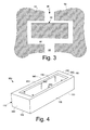
Fig. 3 is a side cross-sectional view of a known seal positioned between adjacent turbine components. -
Fig. 4 is a perspective view of a solid seal as may be described herein with a number of cooling pathways extending therethrough. -
Fig. 5 is a side cross-sectional view of the solid seal ofFig. 4 with the cooling pathways extending therethrough. - Referring now to the drawings, in which like numerals refer to like elements throughout the several views,
Fig. 1 shows a schematic view of gas turbine engine 10 as may be used herein. The gas turbine engine 10 may include acompressor 15. Thecompressor 15 compresses an incoming flow ofair 20. Thecompressor 15 delivers the compressed flow ofair 20 to acombustor 25. Thecombustor 25 mixes the compressed flow ofair 20 with a pressurized flow offuel 30 and ignites the mixture to create a flow ofcombustion gases 35. Although only asingle combustor 25 is shown, the gas turbine engine 10 may include any number ofcombustors 25. The flow ofcombustion gases 35 is in turn delivered to aturbine 40. The flow ofcombustion gases 35 drives theturbine 40 so as to produce mechanical work. The mechanical work produced in theturbine 40 drives thecompressor 15 via ashaft 45 and anexternal load 50 such as an electrical generator and the like. - The gas turbine engine 10 may use natural gas, various types of syngas, and/or other types of fuels. The gas turbine engine 10 may be any one of a number of different gas turbine engines offered by General Electric Company of Schenectady, New York, including, but not limited to, those such as a 7 or a 9 series heavy duty gas turbine engine and the like. The gas turbine engine 10 may have different configurations and may use other types of components. Other types of gas turbine engines also may be used herein. Multiple gas turbine engines, other types of turbines, and other types of power generation equipment also may be used herein together.
-
Fig. 2 shows a portion of theturbine 40. Generally described, theturbine 40 may include afirst stage nozzle 55, afirst stage bucket 60, and afirst stage shroud 62 of afirst stage 65. Also shown is asecond stage nozzle 70 of asecond stage 75. Any number of stages may be used herein. Thenozzles diaphragm 80. Any number ofnozzles 70 anddiaphragms 80 may be positioned circumferentially about anaxis 85. Aseal 90 may be positioned between each pair ofadjacent shrouds 62,diaphragms 80, or other turbine components. Theseal 90 may be used between adjacent turbine components so as to prevent the leakage of the cooling air flows 20 from thecompressor 15 or elsewhere therethrough. As described above, theseals 90 may have many different configurations. Other types of sealing mechanisms also may be used. Other components and other configurations may be used herein. -
Fig. 3 shows an example of theseal 90 positioned between adjacent turbine components, afirst component 92 and asecond component 94. Thecomponents turbine components seal slot 95 therebetween. Theseal 90 may be a solid material seal although other types of seals may be used. Any number of theseals 90 may be used herein. Theseals 90 may prevent or reduce leakage of a flow of highpressure cooling air 96 between thecomponents hot gas path 98. -
Fig. 4 shows an example of aseal 100 as may be described herein. Theseal 100 may have atop surface 110, a bottom surface 120 (a slash face), afirst side 130, an opposedsecond side 140, afirst end 150, and an opposedsecond end 160. (The terms "bottom," "top," "side," "end," "first," "second," and the like are used for the purposes of relative orientation only and not as an absolute position.) Theseal 100 may be a solid seal 170. Alternatively, theseal 100 may have a number of layers of material therein. Theseal 100 may be made out of a high temperature material such as stainless steel, nickel-based alloys, and the like. Other types of materials also may be used herein. Theseal 100 may have any size, shape, or configuration. - As is shown in cross-section in
Fig. 5 , theseal 100 may have a substantial "I-beam" like shape 180. Specifically, theseal 100 may include afirst plenum 190 defined by a firstperipheral lip 200 about thetop surface 110 thereof and asecond plenum 210 defined by a secondperipheral lip 220 about thebottom surface 120 thereof. Theplenums top surface 110 and thebottom surface 120 of the seal. Theplenums peripheral lips Multiple plenums peripheral lips end 230 on thefirst end 150 and a second blockedend 240 on thesecond end 160. The blocked ends 220, 240 may have any size, shape, or configuration. One or more open ends also may be used. Alternatively, the blocked ends 220, 240 may have cooling holes or slots positioned therein. Other components and other configurations may be used herein. - The
seal 100 also may include a number ofcooling pathways 250 extending therethrough from thefirst plenum 190 to thesecond plenum 210. Any number of the coolingpathways 250 may be used herein. The coolingpathways 250 may have any suitable size, shape, or configuration. Further, the coolingpathways 250 may extend through theseal 100 at a straight and/or an angled configuration. Any angle or combinations of angles may be used. The coolingpathways 250 may be formed by drilling or other types of manufacturing techniques. Coolingpathways 250 of differing configurations may be used herein together. Other components and other configurations may be used herein. - In use, the
seal 100 may be positioned between thefirst component 92 and thesecond component 94 within theseal slot 95. Thetop surface 110 of theseal 100 may face the highpressure cooling air 96 while thebottom surface 120 may face the lower pressurehot gas path 98. Theseal 100 may have any number of the coolingpathways 250 extending therethrough in any configuration. Theseal cooling pathways 250 extending into thesecond plenum 210 also act as impingement holes and/or purge holes for theseal slot 95. Specifically, the pressure differential between the highpressure cooling air 96 and the lower pressurehot gas path 98 draws the highpressure cooling air 96 through the coolingpathways 250 and into thesecond plenum 210 about thebottom surface 120 of theseal 100. The highpressure cooling air 96 thus enhances heat transfer through theseal 100 and impinges upon/purges theseal slot 95 via the impingement holes. - The cooling
pathways 250 may be positioned strategically near localized hot spots or uniformly along the length of theseal 100. The coolingpathways 250 may have any prescribed pitch along the length of theseal 100. The use of the blocked ends 230, 240 also substantially limits any gap leakage about theends seal 100. Theseal 100 and the coolingpathways 250 therethrough thus provide purging and cooling of thebottom surface 120 or the slash face as well as about the sealingslot 95 in an efficient manner. - Moreover, the
seal 100 described herein may provide increased seal lifetime, reduced secondary flows, higher overall engine efficiency, and a reduced heat rate. Theseal 100 may be original equipment or part of a retro-fit. Different configurations of theseals 100 may be used together herein. Theseal 100 also may be applicable for use in other types of sealing locations. Specifically, theseal 100 may be used between any two components with a pressure differential therebetween for a flow of cooling air.
Claims (15)
- A seal (100) for use between components facing a high pressure cooling air flow (96) and a hot gas path (98) in a gas turbine engine, comprising:a first surface (190) facing the high pressure cooling air flow;a second surface (210) facing the hot gas path;the second surface comprising a second surface air plenum; anda plurality of cooling pathways (250) extending from the first surface to the second surface air plenum of the second surface for the high pressure cooling air flow to pass therethrough.
- The seal of claim 1, wherein the seal comprises a solid seal.
- The seal of claim 1 or claim 2, wherein the seal comprises a substantial "I" beam-like shape.
- The seal of any preceding claim, wherein the second surface (210) comprises a second surface peripheral lip.
- The seal of any preceding claim, wherein the first surface (190) comprises a first surface air plenum.
- The seal of any preceding claim, wherein the first surface (190) comprises a first surface peripheral lip (200).
- The seal of any preceding claim, wherein the first surface (190) comprises a top surface and wherein the second surface (210) comprises a bottom surface.
- The seal of any preceding claim, further comprising a first blocked end and a second blocked end.
- The seal of any preceding claim, wherein the plurality of cooling holes comprises a straight configuration.
- The seal of any preceding claim, wherein the plurality of cooling holes comprises an angled configuration.
- The seal of any preceding claim, wherein the plurality of cooling holes comprises a plurality of impingement holes.
- The seal of any preceding claim, wherein the components comprise a first stator and a second stator
- The seal of any preceding claim, wherein the components define a seal slot and wherein the seal slot is cooled via the high pressure cooling air flow from the plurality of cooling pathways.
- A method of cooling a seal positioned between components in a gas turbine engine, comprising:flowing high pressure cooling air about a first surface of the seal;drawing the high pressure cooling air through a plurality of cooling pathways in the seal; anddrawing the high pressure cooling air through an air plenum about a second surface of the seal towards a hot gas path.
- The method of claim 14, further comprising the step of cooling the components with the high pressure cooling air leaving the air plenum.
Applications Claiming Priority (1)
| Application Number | Priority Date | Filing Date | Title |
|---|---|---|---|
| US13/633,890 US20140093353A1 (en) | 2012-10-03 | 2012-10-03 | Solid seal with cooling pathways |
Publications (1)
| Publication Number | Publication Date |
|---|---|
| EP2716876A1 true EP2716876A1 (en) | 2014-04-09 |
Family
ID=49322199
Family Applications (1)
| Application Number | Title | Priority Date | Filing Date |
|---|---|---|---|
| EP13186957.0A Withdrawn EP2716876A1 (en) | 2012-10-03 | 2013-10-01 | Solid seal with cooling pathways |
Country Status (4)
| Country | Link |
|---|---|
| US (1) | US20140093353A1 (en) |
| EP (1) | EP2716876A1 (en) |
| JP (1) | JP2014074406A (en) |
| CN (1) | CN103711530A (en) |
Cited By (1)
| Publication number | Priority date | Publication date | Assignee | Title |
|---|---|---|---|---|
| EP3088681A1 (en) * | 2015-04-28 | 2016-11-02 | General Electric Company | Seals with cooling pathways and metered cooling |
Families Citing this family (3)
| Publication number | Priority date | Publication date | Assignee | Title |
|---|---|---|---|---|
| US20130234396A1 (en) * | 2012-03-09 | 2013-09-12 | General Electric Company | Transition Piece Aft-Frame Seals |
| GB201603556D0 (en) * | 2016-03-01 | 2016-04-13 | Rolls Royce Plc | An intercomponent seal for a gas turbine engine |
| JP6650849B2 (en) | 2016-08-25 | 2020-02-19 | 三菱日立パワーシステムズ株式会社 | gas turbine |
Citations (6)
| Publication number | Priority date | Publication date | Assignee | Title |
|---|---|---|---|---|
| GB2195403A (en) * | 1986-09-17 | 1988-04-07 | Rolls Royce Plc | Improvements in or relating to sealing and cooling means |
| US5388962A (en) * | 1993-10-15 | 1995-02-14 | General Electric Company | Turbine rotor disk post cooling system |
| EP1521018A1 (en) * | 2003-10-02 | 2005-04-06 | ALSTOM Technology Ltd | High temperature seal |
| US20060083620A1 (en) * | 2004-10-15 | 2006-04-20 | Siemens Westinghouse Power Corporation | Cooling system for a seal for turbine vane shrouds |
| US20080118346A1 (en) * | 2006-11-21 | 2008-05-22 | Siemens Power Generation, Inc. | Air seal unit adapted to be positioned adjacent blade structure in a gas turbine |
| DE102007062681A1 (en) * | 2007-12-24 | 2009-06-25 | Man Turbo Ag | Sealing segment and sealing segment arrangement |
Family Cites Families (1)
| Publication number | Priority date | Publication date | Assignee | Title |
|---|---|---|---|---|
| US8382424B1 (en) * | 2010-05-18 | 2013-02-26 | Florida Turbine Technologies, Inc. | Turbine vane mate face seal pin with impingement cooling |
-
2012
- 2012-10-03 US US13/633,890 patent/US20140093353A1/en not_active Abandoned
-
2013
- 2013-09-27 JP JP2013200713A patent/JP2014074406A/en active Pending
- 2013-09-29 CN CN201310454279.6A patent/CN103711530A/en active Pending
- 2013-10-01 EP EP13186957.0A patent/EP2716876A1/en not_active Withdrawn
Patent Citations (6)
| Publication number | Priority date | Publication date | Assignee | Title |
|---|---|---|---|---|
| GB2195403A (en) * | 1986-09-17 | 1988-04-07 | Rolls Royce Plc | Improvements in or relating to sealing and cooling means |
| US5388962A (en) * | 1993-10-15 | 1995-02-14 | General Electric Company | Turbine rotor disk post cooling system |
| EP1521018A1 (en) * | 2003-10-02 | 2005-04-06 | ALSTOM Technology Ltd | High temperature seal |
| US20060083620A1 (en) * | 2004-10-15 | 2006-04-20 | Siemens Westinghouse Power Corporation | Cooling system for a seal for turbine vane shrouds |
| US20080118346A1 (en) * | 2006-11-21 | 2008-05-22 | Siemens Power Generation, Inc. | Air seal unit adapted to be positioned adjacent blade structure in a gas turbine |
| DE102007062681A1 (en) * | 2007-12-24 | 2009-06-25 | Man Turbo Ag | Sealing segment and sealing segment arrangement |
Cited By (2)
| Publication number | Priority date | Publication date | Assignee | Title |
|---|---|---|---|---|
| EP3088681A1 (en) * | 2015-04-28 | 2016-11-02 | General Electric Company | Seals with cooling pathways and metered cooling |
| US9581037B2 (en) | 2015-04-28 | 2017-02-28 | General Electric Company | Seals with cooling pathways and metered cooling |
Also Published As
| Publication number | Publication date |
|---|---|
| US20140093353A1 (en) | 2014-04-03 |
| JP2014074406A (en) | 2014-04-24 |
| CN103711530A (en) | 2014-04-09 |
Similar Documents
| Publication | Publication Date | Title |
|---|---|---|
| US9869201B2 (en) | Impingement cooled spline seal | |
| EP3061918B1 (en) | Tapered gas turbine segment seals | |
| EP2612995B1 (en) | Turbine nozzle compartmentalized cooling system | |
| US8613451B2 (en) | Cloth seal for turbo-machinery | |
| EP2634369B1 (en) | Turbine buckets and corresponding forming method | |
| US9816388B1 (en) | Seal in a gas turbine engine having a shim base and a honeycomb structure with a number of cavities formed therein | |
| EP2716875A2 (en) | Spline seal with cooling pathways | |
| US20100329862A1 (en) | Cooling Hole Exits for a Turbine Bucket Tip Shroud | |
| EP2716876A1 (en) | Solid seal with cooling pathways | |
| US9416666B2 (en) | Turbine blade platform cooling systems | |
| EP2615253A1 (en) | Turbine Vane Seal Carrier with Slots for Cooling and Assembly | |
| EP2586994B1 (en) | Metallic stator seal | |
| US9890653B2 (en) | Gas turbine bucket shanks with seal pins | |
| JP6671895B2 (en) | Gas turbine nozzle | |
| EP3088681B1 (en) | Seals with cooling pathways and metered cooling and corresponding method |
Legal Events
| Date | Code | Title | Description |
|---|---|---|---|
| PUAI | Public reference made under article 153(3) epc to a published international application that has entered the european phase |
Free format text: ORIGINAL CODE: 0009012 |
|
| AK | Designated contracting states |
Kind code of ref document: A1 Designated state(s): AL AT BE BG CH CY CZ DE DK EE ES FI FR GB GR HR HU IE IS IT LI LT LU LV MC MK MT NL NO PL PT RO RS SE SI SK SM TR |
|
| AX | Request for extension of the european patent |
Extension state: BA ME |
|
| STAA | Information on the status of an ep patent application or granted ep patent |
Free format text: STATUS: THE APPLICATION IS DEEMED TO BE WITHDRAWN |
|
| 18D | Application deemed to be withdrawn |
Effective date: 20141010 |