EP2716596A1 - Reformer - Google Patents
Reformer Download PDFInfo
- Publication number
- EP2716596A1 EP2716596A1 EP12792000.7A EP12792000A EP2716596A1 EP 2716596 A1 EP2716596 A1 EP 2716596A1 EP 12792000 A EP12792000 A EP 12792000A EP 2716596 A1 EP2716596 A1 EP 2716596A1
- Authority
- EP
- European Patent Office
- Prior art keywords
- reforming
- passage
- layer
- separation
- heating
- Prior art date
- Legal status (The legal status is an assumption and is not a legal conclusion. Google has not performed a legal analysis and makes no representation as to the accuracy of the status listed.)
- Granted
Links
Images




Classifications
-
- B—PERFORMING OPERATIONS; TRANSPORTING
- B01—PHYSICAL OR CHEMICAL PROCESSES OR APPARATUS IN GENERAL
- B01J—CHEMICAL OR PHYSICAL PROCESSES, e.g. CATALYSIS OR COLLOID CHEMISTRY; THEIR RELEVANT APPARATUS
- B01J7/00—Apparatus for generating gases
-
- B—PERFORMING OPERATIONS; TRANSPORTING
- B01—PHYSICAL OR CHEMICAL PROCESSES OR APPARATUS IN GENERAL
- B01J—CHEMICAL OR PHYSICAL PROCESSES, e.g. CATALYSIS OR COLLOID CHEMISTRY; THEIR RELEVANT APPARATUS
- B01J19/00—Chemical, physical or physico-chemical processes in general; Their relevant apparatus
- B01J19/24—Stationary reactors without moving elements inside
- B01J19/248—Reactors comprising multiple separated flow channels
- B01J19/249—Plate-type reactors
-
- C—CHEMISTRY; METALLURGY
- C01—INORGANIC CHEMISTRY
- C01B—NON-METALLIC ELEMENTS; COMPOUNDS THEREOF; METALLOIDS OR COMPOUNDS THEREOF NOT COVERED BY SUBCLASS C01C
- C01B3/00—Hydrogen; Gaseous mixtures containing hydrogen; Separation of hydrogen from mixtures containing it; Purification of hydrogen; Reversible storage of hydrogen
- C01B3/02—Production of hydrogen; Production of gaseous mixtures containing hydrogen
- C01B3/32—Production of hydrogen; Production of gaseous mixtures containing hydrogen by reaction of gaseous or liquid organic compounds with gasifying agents, e.g. water, carbon dioxide or air
- C01B3/34—Production of hydrogen; Production of gaseous mixtures containing hydrogen by reaction of gaseous or liquid organic compounds with gasifying agents, e.g. water, carbon dioxide or air by reaction of hydrocarbons with gasifying agents
- C01B3/38—Production of hydrogen; Production of gaseous mixtures containing hydrogen by reaction of gaseous or liquid organic compounds with gasifying agents, e.g. water, carbon dioxide or air by reaction of hydrocarbons with gasifying agents using catalysts
- C01B3/384—Production of hydrogen; Production of gaseous mixtures containing hydrogen by reaction of gaseous or liquid organic compounds with gasifying agents, e.g. water, carbon dioxide or air by reaction of hydrocarbons with gasifying agents using catalysts with external heating of the catalyst
-
- H—ELECTRICITY
- H01—ELECTRIC ELEMENTS
- H01M—PROCESSES OR MEANS, e.g. BATTERIES, FOR THE DIRECT CONVERSION OF CHEMICAL ENERGY INTO ELECTRICAL ENERGY
- H01M8/00—Fuel cells; Manufacture thereof
- H01M8/06—Combination of fuel cells with means for production of reactants or for treatment of residues
- H01M8/0606—Combination of fuel cells with means for production of reactants or for treatment of residues with means for production of gaseous reactants
- H01M8/0612—Combination of fuel cells with means for production of reactants or for treatment of residues with means for production of gaseous reactants from carbon-containing material
-
- B—PERFORMING OPERATIONS; TRANSPORTING
- B01—PHYSICAL OR CHEMICAL PROCESSES OR APPARATUS IN GENERAL
- B01J—CHEMICAL OR PHYSICAL PROCESSES, e.g. CATALYSIS OR COLLOID CHEMISTRY; THEIR RELEVANT APPARATUS
- B01J2219/00—Chemical, physical or physico-chemical processes in general; Their relevant apparatus
- B01J2219/24—Stationary reactors without moving elements inside
- B01J2219/2401—Reactors comprising multiple separate flow channels
- B01J2219/245—Plate-type reactors
- B01J2219/2451—Geometry of the reactor
- B01J2219/2453—Plates arranged in parallel
-
- B—PERFORMING OPERATIONS; TRANSPORTING
- B01—PHYSICAL OR CHEMICAL PROCESSES OR APPARATUS IN GENERAL
- B01J—CHEMICAL OR PHYSICAL PROCESSES, e.g. CATALYSIS OR COLLOID CHEMISTRY; THEIR RELEVANT APPARATUS
- B01J2219/00—Chemical, physical or physico-chemical processes in general; Their relevant apparatus
- B01J2219/24—Stationary reactors without moving elements inside
- B01J2219/2401—Reactors comprising multiple separate flow channels
- B01J2219/245—Plate-type reactors
- B01J2219/2451—Geometry of the reactor
- B01J2219/2456—Geometry of the plates
- B01J2219/2458—Flat plates, i.e. plates which are not corrugated or otherwise structured, e.g. plates with cylindrical shape
-
- B—PERFORMING OPERATIONS; TRANSPORTING
- B01—PHYSICAL OR CHEMICAL PROCESSES OR APPARATUS IN GENERAL
- B01J—CHEMICAL OR PHYSICAL PROCESSES, e.g. CATALYSIS OR COLLOID CHEMISTRY; THEIR RELEVANT APPARATUS
- B01J2219/00—Chemical, physical or physico-chemical processes in general; Their relevant apparatus
- B01J2219/24—Stationary reactors without moving elements inside
- B01J2219/2401—Reactors comprising multiple separate flow channels
- B01J2219/245—Plate-type reactors
- B01J2219/2461—Heat exchange aspects
- B01J2219/2465—Two reactions in indirect heat exchange with each other
-
- B—PERFORMING OPERATIONS; TRANSPORTING
- B01—PHYSICAL OR CHEMICAL PROCESSES OR APPARATUS IN GENERAL
- B01J—CHEMICAL OR PHYSICAL PROCESSES, e.g. CATALYSIS OR COLLOID CHEMISTRY; THEIR RELEVANT APPARATUS
- B01J2219/00—Chemical, physical or physico-chemical processes in general; Their relevant apparatus
- B01J2219/24—Stationary reactors without moving elements inside
- B01J2219/2401—Reactors comprising multiple separate flow channels
- B01J2219/245—Plate-type reactors
- B01J2219/2474—Mixing means, e.g. fins or baffles attached to the plates
-
- B—PERFORMING OPERATIONS; TRANSPORTING
- B01—PHYSICAL OR CHEMICAL PROCESSES OR APPARATUS IN GENERAL
- B01J—CHEMICAL OR PHYSICAL PROCESSES, e.g. CATALYSIS OR COLLOID CHEMISTRY; THEIR RELEVANT APPARATUS
- B01J2219/00—Chemical, physical or physico-chemical processes in general; Their relevant apparatus
- B01J2219/24—Stationary reactors without moving elements inside
- B01J2219/2401—Reactors comprising multiple separate flow channels
- B01J2219/245—Plate-type reactors
- B01J2219/2476—Construction materials
- B01J2219/2477—Construction materials of the catalysts
- B01J2219/2479—Catalysts coated on the surface of plates or inserts
-
- B—PERFORMING OPERATIONS; TRANSPORTING
- B01—PHYSICAL OR CHEMICAL PROCESSES OR APPARATUS IN GENERAL
- B01J—CHEMICAL OR PHYSICAL PROCESSES, e.g. CATALYSIS OR COLLOID CHEMISTRY; THEIR RELEVANT APPARATUS
- B01J2219/00—Chemical, physical or physico-chemical processes in general; Their relevant apparatus
- B01J2219/24—Stationary reactors without moving elements inside
- B01J2219/2401—Reactors comprising multiple separate flow channels
- B01J2219/245—Plate-type reactors
- B01J2219/2491—Other constructional details
- B01J2219/2492—Assembling means
- B01J2219/2493—Means for assembling plates together, e.g. sealing means, screws, bolts
-
- C—CHEMISTRY; METALLURGY
- C01—INORGANIC CHEMISTRY
- C01B—NON-METALLIC ELEMENTS; COMPOUNDS THEREOF; METALLOIDS OR COMPOUNDS THEREOF NOT COVERED BY SUBCLASS C01C
- C01B2203/00—Integrated processes for the production of hydrogen or synthesis gas
- C01B2203/02—Processes for making hydrogen or synthesis gas
- C01B2203/0266—Processes for making hydrogen or synthesis gas containing a decomposition step
- C01B2203/0277—Processes for making hydrogen or synthesis gas containing a decomposition step containing a catalytic decomposition step
-
- C—CHEMISTRY; METALLURGY
- C01—INORGANIC CHEMISTRY
- C01B—NON-METALLIC ELEMENTS; COMPOUNDS THEREOF; METALLOIDS OR COMPOUNDS THEREOF NOT COVERED BY SUBCLASS C01C
- C01B2203/00—Integrated processes for the production of hydrogen or synthesis gas
- C01B2203/06—Integration with other chemical processes
- C01B2203/066—Integration with other chemical processes with fuel cells
-
- C—CHEMISTRY; METALLURGY
- C01—INORGANIC CHEMISTRY
- C01B—NON-METALLIC ELEMENTS; COMPOUNDS THEREOF; METALLOIDS OR COMPOUNDS THEREOF NOT COVERED BY SUBCLASS C01C
- C01B2203/00—Integrated processes for the production of hydrogen or synthesis gas
- C01B2203/08—Methods of heating or cooling
- C01B2203/0805—Methods of heating the process for making hydrogen or synthesis gas
- C01B2203/0811—Methods of heating the process for making hydrogen or synthesis gas by combustion of fuel
-
- C—CHEMISTRY; METALLURGY
- C01—INORGANIC CHEMISTRY
- C01B—NON-METALLIC ELEMENTS; COMPOUNDS THEREOF; METALLOIDS OR COMPOUNDS THEREOF NOT COVERED BY SUBCLASS C01C
- C01B2203/00—Integrated processes for the production of hydrogen or synthesis gas
- C01B2203/08—Methods of heating or cooling
- C01B2203/0805—Methods of heating the process for making hydrogen or synthesis gas
- C01B2203/0811—Methods of heating the process for making hydrogen or synthesis gas by combustion of fuel
- C01B2203/0822—Methods of heating the process for making hydrogen or synthesis gas by combustion of fuel the fuel containing hydrogen
-
- C—CHEMISTRY; METALLURGY
- C01—INORGANIC CHEMISTRY
- C01B—NON-METALLIC ELEMENTS; COMPOUNDS THEREOF; METALLOIDS OR COMPOUNDS THEREOF NOT COVERED BY SUBCLASS C01C
- C01B2203/00—Integrated processes for the production of hydrogen or synthesis gas
- C01B2203/10—Catalysts for performing the hydrogen forming reactions
- C01B2203/1005—Arrangement or shape of catalyst
- C01B2203/1035—Catalyst coated on equipment surfaces, e.g. reactor walls
-
- Y—GENERAL TAGGING OF NEW TECHNOLOGICAL DEVELOPMENTS; GENERAL TAGGING OF CROSS-SECTIONAL TECHNOLOGIES SPANNING OVER SEVERAL SECTIONS OF THE IPC; TECHNICAL SUBJECTS COVERED BY FORMER USPC CROSS-REFERENCE ART COLLECTIONS [XRACs] AND DIGESTS
- Y02—TECHNOLOGIES OR APPLICATIONS FOR MITIGATION OR ADAPTATION AGAINST CLIMATE CHANGE
- Y02E—REDUCTION OF GREENHOUSE GAS [GHG] EMISSIONS, RELATED TO ENERGY GENERATION, TRANSMISSION OR DISTRIBUTION
- Y02E60/00—Enabling technologies; Technologies with a potential or indirect contribution to GHG emissions mitigation
- Y02E60/30—Hydrogen technology
- Y02E60/50—Fuel cells
-
- Y—GENERAL TAGGING OF NEW TECHNOLOGICAL DEVELOPMENTS; GENERAL TAGGING OF CROSS-SECTIONAL TECHNOLOGIES SPANNING OVER SEVERAL SECTIONS OF THE IPC; TECHNICAL SUBJECTS COVERED BY FORMER USPC CROSS-REFERENCE ART COLLECTIONS [XRACs] AND DIGESTS
- Y02—TECHNOLOGIES OR APPLICATIONS FOR MITIGATION OR ADAPTATION AGAINST CLIMATE CHANGE
- Y02P—CLIMATE CHANGE MITIGATION TECHNOLOGIES IN THE PRODUCTION OR PROCESSING OF GOODS
- Y02P20/00—Technologies relating to chemical industry
- Y02P20/10—Process efficiency
Definitions
- the present invention relates to a reformer including a reforming layer and a heating layer stacked on each other, and particularly to a reformer configured to supply a reformed gas by heating a reforming layer through an exothermic reaction with a combustion catalyst.
- a hydrogen-rich gas is supplied as a fuel gas, and power is generated by an electrochemical reaction of oxygen used as an oxidant with hydrogen, carbon monoxide, and hydrocarbons.
- a method may be adopted which supplies a reformed gas obtained by reforming a liquid fuel.
- a high-carbon organic liquid including gasoline is vaporized and gasified or a fuel gas is used as a reforming fuel.
- the reforming is performed by introducing the reforming fuel into a reformer together with other components necessary for the reforming reaction.
- the reforming fuel is reformed with a reforming catalyst in the reformer. Since the reforming reaction requires heat, it is important to widely supply the whole area of the reforming catalyst with heat in a right amount without excess and deficiency.
- Patent Literature 1 discloses an example of such reformers.
- a combustion passage and a reforming passage are disposed with a wall therebetween, and a combustion gas supplied to the combustion passage is combusted on a combustion catalyst to generate heat. This heat is conducted to a reforming catalyst in the reforming passage for a reforming reaction in the reforming layer.
- a to-be-combusted gas is introduced separately from a combustion-assisting gas by using a pipe to a site where heat is desired to be generated in the combustion passage, so that an exothermic reaction takes place on the entire combustion catalyst.
- Patent Literature 1 Japanese Patent Application Publication No. 2002-80203
- An object of the present invention is to provide a reformer having a simple structure and enabling an exothermic reaction to take place widely on an entire combustion catalyst.
- a reformer according to the present invention is formed by stacking each other a reforming layer configured to reform a reforming fuel with a reforming catalyst, and a heating layer configured to heat the reforming layer through an exothermic reaction with a combustion catalyst.
- a gas mixture obtained by mixing a to-be-combusted gas with a combustion-assisting gas is supplied to a heating passage in the heating layer.
- the heating passage is separated into multiple separation passages by a separation wall parallel to a wall surface coated with the combustion catalyst. The multiple separation passages respectively eject the gas mixture to different positions of the combustion catalyst.
- Fig. 1 shows views for illustrating a structure of a reformer according to the present embodiment.
- Fig. 1(a) is a perspective view for illustrating the entire configuration
- Fig. 1(b) is an exploded perspective view of a reforming layer and a heating layer.
- a reformer 1 includes reforming layers 2 each configured to reform a reforming fuel with a reforming catalyst, heating layers 3 each configured to heat the reforming layer 2 through an exothermic reaction with a combustion catalyst, the layers stacked on each other, and outer walls 4 stacked on the uppermost and lowermost layers.
- the four reforming layers 2 and the three heating layers 3 are stacked, but the number of the layers stacked is not limited thereto.
- the reforming layer 2 is formed by stacking each other: a metal plate 6 coated with a reforming catalyst 5; a metal frame 7 configured to define a height of a reforming passage; and a metal plate 9 having a lower surface closer to the reforming layer and coated with the reforming catalyst 5, and an upper surface closer to the heating layer and coated with a combustion catalyst 8.
- a diffusion structure 15 is disposed on the metal plate 6 so that a reforming fuel flowing thereto can diffuse.
- This diffusion structure 15 is, for example, fins arranged in a zigzag manner shown in Fig. 1 (b) , a porous metal shown in Fig. 2 , a baffle board, or the like.
- the heating layer 3 is formed by stacking each other: the metal plate 9 coated with the combustion catalyst 8; a first metal frame 10 configured to define part of a height of a heating passage; a first separation wall 11, which is a metal plate having a wall surface provided with an opening in a portion thereof; a second metal frame 12 configured to define part of the height of the heating passage; a second separation wall 13, which is a metal plate provided with an opening at a position different from that of the first separation wall 11; a third metal frame 14 configured to define part of the height of the heating passage; and the outer wall 4 formed from a metal plate.
- a diffusion structure 16 is disposed on the metal plate 9 coated with the combustion catalyst 8 so that a to-be-combusted gas and a combustion-assisting gas flowing thereto can diffuse.
- This diffusion structure 16 is, for example, the fins arranged in a zigzag manner shown in Fig. 1(b) , the porous metal shown in Fig. 2 , the baffle board, or the like.
- heights of the first to third metal frames 10, 12, 14 configured to define the parts of the height of the heating passage are equal to a divided height of a normal heating passage, and are not to increase the height of the entire heating passage.
- the height of each of the first to third metal frames 10, 12, 14 is approximately 0.2 mm
- a height of the metal frame 7 defining the height of the reforming passage is approximately 0.5 mm.
- the stacked reformer 1 according to the present embodiment can be produced by stacking each other the reforming layer 2 and the heating layer 3 having such configurations, and joining outer peripheral surfaces thereof together by welding.
- the reformer 1 As shown in Fig. 3(a) , the reformer 1 according to the present embodiment is formed by stacking the reforming layer 2 and the heating layer 3 each other, and a reformed gas reformed by the reforming layer 2 is supplied to a fuel cell 30. Then, components remaining after a reaction by the fuel cell 30 circulate as a to-be-combusted gas to the heating layers 3.
- Fig. 3(b) shows an enlarged sectional view of the reforming layer 2 and the heating layer 3 of the reformer 1 having the configuration as described above.
- each of passage walls 21, 22, which are parallel walls is coated with the reforming catalyst 5; in the heating layer 3, only a passage wall 23 of passage walls 23, 24, which are parallel walls, is coated with the combustion catalyst 8.
- the passage wall 23 is located adjacent to the reforming layer 2.
- a gas mixture obtained by mixing a to-be-combusted gas with a combustion-assisting gas is supplied to a heating passage 25 in the heating layer 3.
- the heating passage 25 is separated into multiple separation passages by the first and second separation walls 11, 13 parallel to the wall surface coated with the combustion catalyst 8.
- the openings of the first separation wall 11 and the second separation wall 13 are arranged at different positions from each other in such a manner that the multiple separation passages respectively eject the gas mixture to different positions of the combustion catalyst 8.
- an opening area of an inlet 26 through which the gas mixture flows into the heating layer 3 is set wider than an opening area of an outlet 27 through which the gas mixture flows out.
- the present embodiment describes an example where the three separation passages are separated by the two separation walls, but the number of separation passages may be two, or may be larger than three.
- a reforming fuel gas is supplied to the reforming passage 28, a reforming reaction takes place with the reforming catalyst 5, and a reformed gas is outputted.
- Fig. 4(a) is an enlarged sectional view of the reforming layer 2 and the heating layer 3
- Figs. 4(b), (c), (d) are respectively cross-sectional views taken along X-X, Y-Y, Z-Z in Fig. 4(a) .
- the description will be given with Fig. 4 of a case where a direction in which a gas flows in the reforming layer 2 is the same as a direction in which a gas flows in the heating layer 3.
- the two first separation wall 11 and second separation wall 13 separate the heating passage 25 in the heating layer 3 into three separation passages 31 a, 31 b, 31 c in the order closest to the reforming layer 2.
- a to-be-combusted gas such as hydrocarbon fuel and hydrogen and a combustion-assisting gas such as air mixed in advance flow into the heating passage 25.
- the gas mixture thus flowed is separated and continues to flow into the three separation passages 31a, 31 b, 31 c.
- the three separation passages 31a, 31b, 31c respectively eject the gas mixture to different positions of the combustion catalyst 8. For example, in Fig.
- the separation passage 31a supplies the gas mixture to a section A of the combustion catalyst 8
- the separation passage 31b ejects the gas mixture to a section B of the combustion catalyst 8
- the separation passage 3 1 c ejects the gas mixture to a section C of the combustion catalyst 8.
- the gas mixture flowed into the separation passage 31a comes into contact with the combustion catalyst 8 immediately after the flowing. Accordingly, heat is generated through a combustion reaction near the inlet of the heating layer 3 to heat the reforming catalyst 5 in the reforming layer 2 with the wall in between, promoting a reforming reaction near an inlet of the reforming layer 2. Meanwhile, the gas mixture flowed into the separation passages 31b, 31c does not come into contact with the combustion catalyst 8 near the inlet of the heating layer 3. Accordingly, the gas mixture further keeps flowing through the heating passage 25 without a combustion reaction.
- the first separation wall 11 separating the separation passage 31b from the separation passage 31 a comes to an end.
- the gas mixture flowing through the separation passage 31b is ejected to the combustion catalyst 8, and a combustion reaction takes place in the section B to generate heat.
- the second separation wall 13 separating the separation passage 31 b from the separation passage 31c comes to an end.
- the gas mixture flowing through the separation passage 31c is ejected to the combustion catalyst 8, and a combustion reaction takes place in the section C to generate heat.
- a wall surface 32 is provided at an outlet of the separation passage 31c, thereby changing the flow of the gas mixture flowing through the separation passage 31 c toward the combustion catalyst 8, and the reaction with the combustion catalyst 8 surely takes place.
- diffusing members 33, 34 are respectively provided, and play a role of changing the flows of the gas mixtures flowing through the separation passages 31 b, 31 c in such a manner that the gas mixtures are guided in a direction to the combustion catalyst 8.
- the exothermic reaction takes place in the entire heating layer 3, and a reforming fuel is reformed into a reformed gas.
- a gas mixture obtained by mixing a to-be-combusted gas with a combustion-assisting gas is supplied to the heating passage 25; the heating passage 25 is separated into the multiple separation passages by the separation walls 11, 13; and the separation passages respectively eject the gas mixture to different positions of the combustion catalyst 8. Accordingly, with a simple structure not using a pipe or the like, an exothermic reaction can take place widely on the entire combustion catalyst 8. This makes it possible to keep a temperature optimal for a reforming reaction in a large area of the reforming layer 2, and a favorable reforming reaction can take place.
- the diffusion structures configured to diffuse gases are provided to the reforming layer 2 and the heating layer 3. Accordingly, flowing gases are diffused, and the reactions can take place in a large area.
- the fins 15, 16 arranged in a zigzag manner are provided as the diffusion structures. This enables efficient diffusion of flowing gases with a simple structure.
- the porous metals are provided as the diffusion structures. Accordingly, flowing gases can be diffused more surely.
- a reformed gas reformed by the reforming layer 2 is supplied as a fuel gas to fuel cells. Accordingly, the utilization as a reformer for fuel cells is possible.
- Fig. 5(a) is an enlarged sectional view of the reforming layer 2 and the heating layer 3
- Figs. 5(b), (c) , (d) are respectively cross-sectional views taken along X-X, Y-Y, Z-Z in Fig. 5(a) .
- the description will be given with Fig. 5 of a case where a direction in which a gas flows in the reforming layer 2 is a direction opposite to a direction in which a gas flows in the heating layer 3.
- the two first separation wall 11 and second separation wall 13 separate the heating passage 25 in the heating layer 3 into the three separation passages 31 a, 31 b, 31 c in the order closest to the reforming layer 2.
- the heating layer 3 needs to increase the temperature of the section C located near the inlet of the reforming layer 2 so that a reforming reaction can take place the most near the inlet of the reforming layer 2 where a reforming fuel gas is supplied. For this reason, positions where the separation passages 31a, 31b, 31c eject the gas mixture need to be shifted closer toward the inlet side of the reforming passage 28 rather than the outlet side thereof.
- a wall surface 51 is provided in such a manner that the gas mixture does not flow into the separation passage 31 a for supplying a gas mixture to the section A located near the outlet of the reforming layer 2.
- the gas mixture thus flowed is separated and continues to flow into the two separation passages 31b, 31c.
- a larger amount of the gas mixture is introduced further into the heating passage 25.
- the gas mixture does not flow into the section A close to the inlet of the heating layer 3, which is not coated with the combustion catalyst 8, either; accordingly, no exothermic reaction takes place there.
- the gas mixture flowing through the separation passage 31b is ejected to the combustion catalyst 8, and a combustion reaction takes place in the section B to generate heat.
- the second separation wall 13 comes to the end in the section C of the heating passage 25 located further than the section B, the gas mixture flowing through the separation passage 31c is ejected to the combustion catalyst 8, and a combustion reaction takes place in the section C to generate heat. This heats the reforming catalyst 5 in the reforming layer 2 with the wall in between, promoting a reforming reaction near the inlet of the reforming layer 2.
- the gas mixture does not flow into the separation passage 31a, and only flows into the separation passages 31b, 31 c.
- This enables the positions where the gas mixture is ejected to the combustion catalyst 8 to be shifted closer toward the inlet side of the reforming passage 28 rather than the outlet side thereof. Thereby, the temperature on the inlet side of the reforming layer 2 is increased, and the reforming reaction can be further promoted.
- the amount of heat generated at each section of the combustion catalyst 8 on the basis of the cross-sectional area of the separation passages 31 a, 31b, 31 c.
- the amount of heat generated in the section C of the combustion catalyst 8 can be set approximately double the amount of heat generated in the section B.
- the reforming reaction of the reforming layer 2 can be further promoted.
- the positions where the separation passages 31a, 31b, 31c eject the gas mixture are shifted closer toward the inlet side of the reforming passage 28 rather than the outlet side thereof. Accordingly, a larger amount of the gas mixture can be supplied to the inlet side of the reforming layer 2 where a large amount of heat generation is required. Thus, the reforming reaction can be promoted by increasing the temperature near the inlet of the reforming layer 2.
- the cross-sectional areas of the separation passages 31a, 31 b, 31 c are set in such a manner that the cross-sectional area is larger for a separation passage ejecting the gas mixture at a position closer to the inlet side of the reforming passage 28. Accordingly, a larger amount of the gas mixture can be supplied to the inlet side of the reforming layer 2 where a large amount of heat generation is required. Thus, the reforming reaction can be promoted by increasing the temperature near the inlet of the reforming layer 2.
- Fig. 6(a) is an enlarged sectional view of the reforming layer 2 and the heating layer 3
- Figs. 6(b), (c), (d) are respectively cross-sectional views taken along X-X, Y-Y, Z-Z in Fig. 6(a) .
- a separation wall 62 separates the heating passage 25 into two separation passages 63a, 63b.
- An arrangement of these the separation passages 63a, 63b viewed from the wall surface coated with the combustion catalyst 8 is switched by a switch section 64 provided in the middle of the heating passage 25. Specifically, on an upstream side of the switch section 64, the separation passage 63a is arranged at a position in contact with the combustion catalyst 8; on a downstream side of the switch section 64, the upper and lower passages are reversed, so that the separation passage 63b is arranged at a position in contact with the combustion catalyst 8.
- the gas mixtures flowing through the respective separation passages 63a, 63b switch the passages in a vertical direction without being mixed at the switch section 64 and continue to flow.
- the gas mixture flowed therein comes into contact with the combustion catalyst 8, and heat is generated in the section A near the inlet of the heating layer 3 to heat the reforming catalyst 5 with the wall in between, promoting a reforming reaction near the inlet of the reforming layer 2.
- the gas mixture flowed into the separation passage 63b does not come into contact with the combustion catalyst 8 before the switch section 64, and further keeps flowing through the heating passage 25 without a reaction. Then, at the switch section 64, the upper and lower positions of the separation passage 63a and the separation passage 64b are reversed.
- a gas mixture flowing through the separation passage 63a on a lower side is shifted to a right side (lower side in Fig. 7 ), while a gas mixture flowing through the separation passage 63b on an upper side is shifted to a left side (upper side in Fig. 7 ).
- the upper and lower positions are reversed.
- the arrangement is altered such that the separation passage 63a having been located on the lower side is then on the upper side, and the separation passage 63b having been located on the upper side is then on the lower side.
- the position where the switch section 64 is provided is preferably located closer to the inlet side of the reforming layer 2 than to the outlet side thereof.
- the switch section 64 is disposed closer to the inlet side of the heating layer 3; when the directions in which gases flow in the reforming layer 2 and in the heating layer 3 are opposite, the switch section 64 is disposed closer to the outlet side of the heating layer 3.
- cross-sectional areas of the separation passages 63a, 63b are preferably larger for a separation passage closer to the combustion catalyst 8 on the inlet side of the reforming passage 28.
- the cross-sectional area of the separation passage 63a is made larger; when the directions in which gases flow in the reforming layer 2 and in the heating layer 3 are opposite, the cross-sectional area of the separation passage 63b is made larger.
- the arrangement of the separation passages is switched in the middle of the heating passage 25. Accordingly, gas mixtures flowing through the respective separation passages are not mixed together, and this makes it possible to prevent dilution of a gas mixture yet to be reacted with a gas mixture having been subjected to a combustion reaction. Thereby, the combustion efficiency can be improved.
- the position of switching the arrangement of the separation passages is located closer to the inlet side of the reforming passage 28 than to the outlet side thereof. Accordingly, more combustion reactions can take place on the inlet side of the reforming layer 2 where a large amount of heat generation is required. Thus, the reforming reaction can be promoted by increasing the temperature near the inlet of the reforming layer 2.
- the cross-sectional area of a separation passage closer to the combustion catalyst 5 on the inlet side of the reforming passage 28 is set larger. Accordingly, a larger amount of the gas mixture can be supplies to the inlet side of the reforming layer 2 where a large amount of heat generation is required. Thus, the reforming reaction can be promoted by increasing the temperature near the inlet of the reforming layer 2.
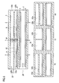
- Fig. 8 shows views for illustrating, in detail, cross-sectional structures of the reforming layers 2 and the heating layer 3.
- a reformer 81 according to the present embodiment has a structure in which the reforming layers 2 are provided adjacent to both sides of the heating layer 3.
- Fig. 8(b) shows an enlarged sectional view of the reforming layers 2 and the heating layer 3 of the reformer 81 having such a configuration.
- Fig. 8(b) shows passage walls on both sides, which are parallel walls, are coated with the reforming catalyst 5; in the heating layer 3 also, passage walls on both sides, which are parallel walls, are coated with the combustion catalyst 8.
- the heating layer 3 is separated into five separation passages 86a to 86e by four separation walls 82 to 85, and has a vertically symmetrical structure around the central separation passage 86c.
- a gas mixture introduced into the heating layer 3 is a to-be-combusted gas and a combustion-assisting gas mixed in advance, and flows into the heating passage 25.
- the gas mixture thus flowed is separated and continues to flow into the five separation passages 86a to 86e.
- the gas mixtures flowed into the separation passages 86a, 86e come into contact with the combustion catalysts 8 immediately after the flowing. Accordingly, heat is generated through a combustion reaction near the inlet of the heating layer 3 to heat the reforming catalysts 5 with walls in between, promoting a reforming reaction near the inlets of the reforming layers 2.
- the gas mixtures flowed into the separation passages 86b to 86d do not come into contact with the combustion catalysts 8 near the inlet of the heating layer 3, and further keeps flowing through the heating passage 25. Then, the separation walls 82, 85 come to ends at the central portion of the heating layer 3, the gas mixtures flowing through the separation passages 86b, 86d are ejected to the combustion catalysts 8, and heat is generated through a combustion reaction to heat the reforming catalysts 5 with the walls in between, promoting a reforming reaction at the central portions of the reforming layers 2.
- the gas mixture flowed into the separation passage 86c keeps flowing through the heating passage 25 much further, and is ejected to the combustion catalysts 8 near the outlet of the heating layer 3 as the separation walls 83, 84 come to ends. Then, a combustion reaction takes place near the outlet of the heating layer 3 to generate heat.
- the reforming catalysts 5 are heated with the walls in between, promoting a reforming reaction near the outlets of the reforming layers 2.
- a gas mixture obtained by mixing a to-be-combusted gas with a combustion-assisting gas is supplied to a heating passage; the heating passage is separated into multiple separation passages by a separation wall; and the separation passages respectively eject the gas mixture to different positions of a combustion catalyst. Accordingly, with a simple structure not using a pipe or the like, an exothermic reaction can take place widely on the entire combustion catalyst. This makes it possible to keep a temperature optimal for a reforming reaction in a large area of a reforming layer, and a favorable reforming reaction can take place. Therefore, the reformer according to one embodiment of the present invention is industrially applicable.
Landscapes
- Chemical & Material Sciences (AREA)
- Chemical Kinetics & Catalysis (AREA)
- Organic Chemistry (AREA)
- Engineering & Computer Science (AREA)
- Life Sciences & Earth Sciences (AREA)
- General Health & Medical Sciences (AREA)
- Combustion & Propulsion (AREA)
- Inorganic Chemistry (AREA)
- Health & Medical Sciences (AREA)
- Manufacturing & Machinery (AREA)
- Sustainable Development (AREA)
- Sustainable Energy (AREA)
- Electrochemistry (AREA)
- General Chemical & Material Sciences (AREA)
- Hydrogen, Water And Hydrids (AREA)
- Fuel Cell (AREA)
Abstract
Description
- The present invention relates to a reformer including a reforming layer and a heating layer stacked on each other, and particularly to a reformer configured to supply a reformed gas by heating a reforming layer through an exothermic reaction with a combustion catalyst.
- Because of increasing concern about global environmental problems, the utilization of various fuel cells has been studied recently. Among these, in a case of a solid oxide fuel cell having a high efficiency, a hydrogen-rich gas is supplied as a fuel gas, and power is generated by an electrochemical reaction of oxygen used as an oxidant with hydrogen, carbon monoxide, and hydrocarbons.
- Moreover, for the fuel gas, a method may be adopted which supplies a reformed gas obtained by reforming a liquid fuel. In such reforming, a high-carbon organic liquid including gasoline is vaporized and gasified or a fuel gas is used as a reforming fuel. The reforming is performed by introducing the reforming fuel into a reformer together with other components necessary for the reforming reaction. In this event, the reforming fuel is reformed with a reforming catalyst in the reformer. Since the reforming reaction requires heat, it is important to widely supply the whole area of the reforming catalyst with heat in a right amount without excess and deficiency.
- Hence, there have been conventionally proposed reformers having a structure, in which a combustion layer and a reforming layer are separated.
Patent Literature 1 discloses an example of such reformers. In the reformer disclosed inPatent Literature 1, a combustion passage and a reforming passage are disposed with a wall therebetween, and a combustion gas supplied to the combustion passage is combusted on a combustion catalyst to generate heat. This heat is conducted to a reforming catalyst in the reforming passage for a reforming reaction in the reforming layer. - Conventionally, in such a reformer, one of simplest ways of supplying a combustion gas is that a to-be-combusted gas and a combustion-assisting gas are mixed together in advance at the outside and are supplied as the combustion gas to the reformer. Nevertheless, in this method, occurrence of an exothermic reaction is localized near an inlet of the combustion passage. This brings about problems that a sufficient amount of heat is not obtained on a downstream side of the combustion passage, and a reforming reaction does not take place sufficiently there.
- For this reason, in the reformer disclosed in
Patent Literature 1, a to-be-combusted gas is introduced separately from a combustion-assisting gas by using a pipe to a site where heat is desired to be generated in the combustion passage, so that an exothermic reaction takes place on the entire combustion catalyst. - Patent Literature 1: Japanese Patent Application Publication No.
2002-80203 - However, in the reformer disclosed in
Patent Literature 1 described above, since the pipe is used to introduce a to-be-combusted gas to each site in the combustion passage, a problem is brought about that the device is complicated by the arrangement of the pipe and so forth. Particularly, the larger the number of combustion layers stacked, the more the complexity of the device. It is important to solve this problem. - Therefore, the present invention has been proposed in view of the above-described circumstances. An object of the present invention is to provide a reformer having a simple structure and enabling an exothermic reaction to take place widely on an entire combustion catalyst.
- A reformer according to the present invention is formed by stacking each other a reforming layer configured to reform a reforming fuel with a reforming catalyst, and a heating layer configured to heat the reforming layer through an exothermic reaction with a combustion catalyst. A gas mixture obtained by mixing a to-be-combusted gas with a combustion-assisting gas is supplied to a heating passage in the heating layer. Moreover, the heating passage is separated into multiple separation passages by a separation wall parallel to a wall surface coated with the combustion catalyst. The multiple separation passages respectively eject the gas mixture to different positions of the combustion catalyst.
-
- [
Fig. 1] Fig. 1 shows views for illustrating a structure of a reformer according to a first embodiment to which the present invention is applied. - [
Fig. 2] Fig. 2 shows a view for illustrating a porous metal disposed in the reformer according to the first embodiment to which the present invention is applied. - [
Fig. 3] Fig. 3 shows views for illustrating, in detail, cross-sectional structures of a reforming layer and a heating layer of the reformer according to the first embodiment to which the present invention is applied. - [
Fig. 4] Fig. 4 shows views for illustrating, in detail, cross-sectional structures of the reforming layer and the heating layer of the reformer according to the first embodiment to which the present invention is applied. - [
Fig. 5] Fig. 5 shows views for illustrating, in detail, cross-sectional structures of a reforming layer and a heating layer of a reformer according to a second embodiment to which the present invention is applied. - [
Fig. 6] Fig. 6 shows views for illustrating, in detail, cross-sectional structures of a reforming layer and a heating layer of a reformer according to a third embodiment to which the present invention is applied. - [
Fig. 7] Fig. 7 shows a view for illustrating a structure of a switch section of the reformer according to the third embodiment to which the present invention is applied. - [
Fig. 8] Fig. 8 shows views for illustrating, in detail, cross-sectional structures of a reforming layer and a heating layer of a reformer according to a fourth embodiment to which the present invention is applied. - Hereinafter, first to fourth embodiments to which the present invention is applied will be described with reference to the drawings.
-
Fig. 1 shows views for illustrating a structure of a reformer according to the present embodiment.Fig. 1(a) is a perspective view for illustrating the entire configuration, andFig. 1(b) is an exploded perspective view of a reforming layer and a heating layer. - As shown in
Fig. 1(a) , areformer 1 according to the present embodiment includes reforminglayers 2 each configured to reform a reforming fuel with a reforming catalyst,heating layers 3 each configured to heat the reforminglayer 2 through an exothermic reaction with a combustion catalyst, the layers stacked on each other, and outer walls 4 stacked on the uppermost and lowermost layers. In the structure illustrated inFig. 1(a) , the four reforminglayers 2 and the threeheating layers 3 are stacked, but the number of the layers stacked is not limited thereto. - Next, structures of the reforming
layer 2 and theheating layer 3 will be described with reference toFig. 1(b) . As shown inFig. 1(b) , the reforminglayer 2 is formed by stacking each other: a metal plate 6 coated with a reformingcatalyst 5; a metal frame 7 configured to define a height of a reforming passage; and a metal plate 9 having a lower surface closer to the reforming layer and coated with the reformingcatalyst 5, and an upper surface closer to the heating layer and coated with acombustion catalyst 8. Here, adiffusion structure 15 is disposed on the metal plate 6 so that a reforming fuel flowing thereto can diffuse. Thisdiffusion structure 15 is, for example, fins arranged in a zigzag manner shown inFig. 1 (b) , a porous metal shown inFig. 2 , a baffle board, or the like. - The
heating layer 3 is formed by stacking each other: the metal plate 9 coated with thecombustion catalyst 8; afirst metal frame 10 configured to define part of a height of a heating passage; afirst separation wall 11, which is a metal plate having a wall surface provided with an opening in a portion thereof; asecond metal frame 12 configured to define part of the height of the heating passage; asecond separation wall 13, which is a metal plate provided with an opening at a position different from that of thefirst separation wall 11; a third metal frame 14 configured to define part of the height of the heating passage; and the outer wall 4 formed from a metal plate. In addition, adiffusion structure 16 is disposed on the metal plate 9 coated with thecombustion catalyst 8 so that a to-be-combusted gas and a combustion-assisting gas flowing thereto can diffuse. Thisdiffusion structure 16 is, for example, the fins arranged in a zigzag manner shown inFig. 1(b) , the porous metal shown inFig. 2 , the baffle board, or the like. - Here, heights of the first to
third metal frames third metal frames - The stacked
reformer 1 according to the present embodiment can be produced by stacking each other the reforminglayer 2 and theheating layer 3 having such configurations, and joining outer peripheral surfaces thereof together by welding. - Next, cross-sectional structures of the reforming
layer 2 and theheating layer 3 will be described in detail with reference toFig. 3 . As shown inFig. 3(a) , thereformer 1 according to the present embodiment is formed by stacking the reforminglayer 2 and theheating layer 3 each other, and a reformed gas reformed by the reforminglayer 2 is supplied to afuel cell 30. Then, components remaining after a reaction by thefuel cell 30 circulate as a to-be-combusted gas to theheating layers 3. -
Fig. 3(b) shows an enlarged sectional view of the reforminglayer 2 and theheating layer 3 of thereformer 1 having the configuration as described above. As shown inFig. 3(b) , in the reforminglayer 2, each ofpassage walls 21, 22, which are parallel walls, is coated with the reformingcatalyst 5; in theheating layer 3, only apassage wall 23 ofpassage walls combustion catalyst 8. Thepassage wall 23 is located adjacent to the reforminglayer 2. - A gas mixture obtained by mixing a to-be-combusted gas with a combustion-assisting gas is supplied to a
heating passage 25 in theheating layer 3. Theheating passage 25 is separated into multiple separation passages by the first andsecond separation walls combustion catalyst 8. Moreover, the openings of thefirst separation wall 11 and thesecond separation wall 13 are arranged at different positions from each other in such a manner that the multiple separation passages respectively eject the gas mixture to different positions of thecombustion catalyst 8. Further, an opening area of aninlet 26 through which the gas mixture flows into theheating layer 3 is set wider than an opening area of anoutlet 27 through which the gas mixture flows out. Note that, the present embodiment describes an example where the three separation passages are separated by the two separation walls, but the number of separation passages may be two, or may be larger than three. - Meanwhile, in the reforming
layer 2, a reforming fuel gas is supplied to the reformingpassage 28, a reforming reaction takes place with the reformingcatalyst 5, and a reformed gas is outputted. - Next, functions of the reforming
layer 2 and theheating layer 3 will be described with reference toFig. 4. Fig. 4(a) is an enlarged sectional view of the reforminglayer 2 and theheating layer 3, andFigs. 4(b), (c), (d) are respectively cross-sectional views taken along X-X, Y-Y, Z-Z inFig. 4(a) . The description will be given withFig. 4 of a case where a direction in which a gas flows in the reforminglayer 2 is the same as a direction in which a gas flows in theheating layer 3. - As shown in
Fig. 4(a) , the twofirst separation wall 11 andsecond separation wall 13 separate theheating passage 25 in theheating layer 3 into threeseparation passages layer 2. - In the
heating layer 3, a to-be-combusted gas such as hydrocarbon fuel and hydrogen and a combustion-assisting gas such as air mixed in advance flow into theheating passage 25. The gas mixture thus flowed is separated and continues to flow into the threeseparation passages separation walls separation passages combustion catalyst 8. For example, inFig. 4(a) , theseparation passage 31a supplies the gas mixture to a section A of thecombustion catalyst 8, theseparation passage 31b ejects the gas mixture to a section B of thecombustion catalyst 8, and theseparation passage 3 1 c ejects the gas mixture to a section C of thecombustion catalyst 8. - In the section A close to the inlet of the
heating layer 3, the gas mixture flowed into theseparation passage 31a comes into contact with thecombustion catalyst 8 immediately after the flowing. Accordingly, heat is generated through a combustion reaction near the inlet of theheating layer 3 to heat the reformingcatalyst 5 in the reforminglayer 2 with the wall in between, promoting a reforming reaction near an inlet of the reforminglayer 2. Meanwhile, the gas mixture flowed into theseparation passages combustion catalyst 8 near the inlet of theheating layer 3. Accordingly, the gas mixture further keeps flowing through theheating passage 25 without a combustion reaction. - In the section B located at a central portion of the
heating layer 3, thefirst separation wall 11 separating theseparation passage 31b from theseparation passage 31 a comes to an end. Thereby, the gas mixture flowing through theseparation passage 31b is ejected to thecombustion catalyst 8, and a combustion reaction takes place in the section B to generate heat. This heats the reformingcatalyst 5 in the reforminglayer 2 with the wall in between, promoting a reforming reaction at a central portion of the reforminglayer 2. - Furthermore, in the section C located near the outlet of the
heating layer 3, thesecond separation wall 13 separating theseparation passage 31 b from theseparation passage 31c comes to an end. Thereby, the gas mixture flowing through theseparation passage 31c is ejected to thecombustion catalyst 8, and a combustion reaction takes place in the section C to generate heat. This heats the reformingcatalyst 5 in the reforminglayer 2 with the wall in between, promoting a reforming reaction near an outlet of the reforminglayer 2. Moreover, awall surface 32 is provided at an outlet of theseparation passage 31c, thereby changing the flow of the gas mixture flowing through theseparation passage 31 c toward thecombustion catalyst 8, and the reaction with thecombustion catalyst 8 surely takes place. - Note that, at portions where the
first separation wall 11 and thesecond separation wall 13 come to the ends, diffusingmembers separation passages combustion catalyst 8. - In this manner, in the
reformer 1 according to the present embodiment, the exothermic reaction takes place in theentire heating layer 3, and a reforming fuel is reformed into a reformed gas. - As has been described above in detail, in the
reformer 1 according to the present embodiment, a gas mixture obtained by mixing a to-be-combusted gas with a combustion-assisting gas is supplied to theheating passage 25; theheating passage 25 is separated into the multiple separation passages by theseparation walls combustion catalyst 8. Accordingly, with a simple structure not using a pipe or the like, an exothermic reaction can take place widely on theentire combustion catalyst 8. This makes it possible to keep a temperature optimal for a reforming reaction in a large area of the reforminglayer 2, and a favorable reforming reaction can take place. - In addition, since the passage can be set wider than a conventional pipe, this makes it possible to introduce the gas mixture to a large area, and an exothermic reaction can take place widely on the
entire combustion catalyst 8. - Moreover, in the
reformer 1 according to the present embodiment, the diffusion structures configured to diffuse gases are provided to the reforminglayer 2 and theheating layer 3. Accordingly, flowing gases are diffused, and the reactions can take place in a large area. - Further, in the
reformer 1 according to the present embodiment, thefins - Additionally, in the
reformer 1 according to the present embodiment, the porous metals are provided as the diffusion structures. Accordingly, flowing gases can be diffused more surely. - Furthermore, in the
reformer 1 according to the present embodiment, a reformed gas reformed by the reforminglayer 2 is supplied as a fuel gas to fuel cells. Accordingly, the utilization as a reformer for fuel cells is possible. - Next, a second embodiment to which the present invention is applied will be described with reference to
Fig. 5 . Note that the same numbers denote the same elements and portions as those in the first embodiment, and the detailed description is omitted.Fig. 5(a) is an enlarged sectional view of the reforminglayer 2 and theheating layer 3, andFigs. 5(b), (c) ,(d) are respectively cross-sectional views taken along X-X, Y-Y, Z-Z inFig. 5(a) . The description will be given withFig. 5 of a case where a direction in which a gas flows in the reforminglayer 2 is a direction opposite to a direction in which a gas flows in theheating layer 3. - As shown in
Fig. 5(a) , in a reformer according to the present embodiment, the twofirst separation wall 11 andsecond separation wall 13 separate theheating passage 25 in theheating layer 3 into the threeseparation passages layer 2. - Here, in order to improve the reforming efficiency as the reformer, the
heating layer 3 needs to increase the temperature of the section C located near the inlet of the reforminglayer 2 so that a reforming reaction can take place the most near the inlet of the reforminglayer 2 where a reforming fuel gas is supplied. For this reason, positions where theseparation passages passage 28 rather than the outlet side thereof. - Accordingly, in the present embodiment, a
wall surface 51 is provided in such a manner that the gas mixture does not flow into theseparation passage 31 a for supplying a gas mixture to the section A located near the outlet of the reforminglayer 2. Thereby, in theheating layer 3 of the present embodiment, the gas mixture thus flowed is separated and continues to flow into the twoseparation passages heating passage 25. Thereby, the gas mixture does not flow into the section A close to the inlet of theheating layer 3, which is not coated with thecombustion catalyst 8, either; accordingly, no exothermic reaction takes place there. - Meanwhile, since the
first separation wall 11 comes to the end in the section B of theheating passage 25 located further than the section A, the gas mixture flowing through theseparation passage 31b is ejected to thecombustion catalyst 8, and a combustion reaction takes place in the section B to generate heat. This heats the reformingcatalyst 5 in the reforminglayer 2 with the wall in between, promoting a reforming reaction at the central portion of the reforminglayer 2. - Furthermore, since the
second separation wall 13 comes to the end in the section C of theheating passage 25 located further than the section B, the gas mixture flowing through theseparation passage 31c is ejected to thecombustion catalyst 8, and a combustion reaction takes place in the section C to generate heat. This heats the reformingcatalyst 5 in the reforminglayer 2 with the wall in between, promoting a reforming reaction near the inlet of the reforminglayer 2. - As described above, in the present embodiment, the gas mixture does not flow into the
separation passage 31a, and only flows into theseparation passages combustion catalyst 8 to be shifted closer toward the inlet side of the reformingpassage 28 rather than the outlet side thereof. Thereby, the temperature on the inlet side of the reforminglayer 2 is increased, and the reforming reaction can be further promoted. - Moreover, it is also possible to change the amount of heat generated at each section of the
combustion catalyst 8 on the basis of the cross-sectional area of theseparation passages separation passage 31c and theseparation passage 31b is 2:1, the amount of heat generated in the section C of thecombustion catalyst 8 can be set approximately double the amount of heat generated in the section B. In this event, by setting a larger cross-sectional area for a separation passage ejecting the gas mixture at a position closer to the inlet side of the reformingpassage 28, the reforming reaction of the reforminglayer 2 can be further promoted. - As has been described above in detail, in the reformer according to the present embodiment, the positions where the
separation passages passage 28 rather than the outlet side thereof. Accordingly, a larger amount of the gas mixture can be supplied to the inlet side of the reforminglayer 2 where a large amount of heat generation is required. Thus, the reforming reaction can be promoted by increasing the temperature near the inlet of the reforminglayer 2. - Moreover, in the reformer according to the present embodiment, the cross-sectional areas of the
separation passages passage 28. Accordingly, a larger amount of the gas mixture can be supplied to the inlet side of the reforminglayer 2 where a large amount of heat generation is required. Thus, the reforming reaction can be promoted by increasing the temperature near the inlet of the reforminglayer 2. - Next, a third embodiment to which the present invention is applied will be described with reference to
Fig. 6 . Note that the same numbers denote the same elements and portions as those in the first and second embodiments, and the detailed description is omitted.Fig. 6(a) is an enlarged sectional view of the reforminglayer 2 and theheating layer 3, andFigs. 6(b), (c), (d) are respectively cross-sectional views taken along X-X, Y-Y, Z-Z inFig. 6(a) . - As shown in
Fig. 6(a) , in a reformer according to the present embodiment, aseparation wall 62 separates theheating passage 25 into twoseparation passages separation passages combustion catalyst 8 is switched by aswitch section 64 provided in the middle of theheating passage 25. Specifically, on an upstream side of theswitch section 64, theseparation passage 63a is arranged at a position in contact with thecombustion catalyst 8; on a downstream side of theswitch section 64, the upper and lower passages are reversed, so that theseparation passage 63b is arranged at a position in contact with thecombustion catalyst 8. - With such a structure, the gas mixtures flowing through the
respective separation passages switch section 64 and continue to flow. Immediately after flowing into theseparation passage 63a, the gas mixture flowed therein comes into contact with thecombustion catalyst 8, and heat is generated in the section A near the inlet of theheating layer 3 to heat the reformingcatalyst 5 with the wall in between, promoting a reforming reaction near the inlet of the reforminglayer 2. - Meanwhile, the gas mixture flowed into the
separation passage 63b does not come into contact with thecombustion catalyst 8 before theswitch section 64, and further keeps flowing through theheating passage 25 without a reaction. Then, at theswitch section 64, the upper and lower positions of theseparation passage 63a and the separation passage 64b are reversed. - Here, an example of the structure of the
switch section 64 will be described with reference toFig. 7 . As shown inFig. 7 , in theswitch section 64, a gas mixture flowing through theseparation passage 63a on a lower side is shifted to a right side (lower side inFig. 7 ), while a gas mixture flowing through theseparation passage 63b on an upper side is shifted to a left side (upper side inFig. 7 ). Then, each separately passes through a vertically-communicating passage. Thus, the upper and lower positions are reversed. The arrangement is altered such that theseparation passage 63a having been located on the lower side is then on the upper side, and theseparation passage 63b having been located on the upper side is then on the lower side. - Thereafter, the gas mixture in the
separation passage 63b not having been in contact with thecombustion catalyst 8 comes into contact with thecombustion catalyst 8, and heat is generated in the section B on the outlet side of theheating layer 3 to heat the reformingcatalyst 5 with the wall in between, promoting a reforming reaction near the outlet of the reforminglayer 2. - Note that, the description has been given with
Fig. 6 of the case of two separation passages as an example. Nevertheless, it is possible to provide three or more separation passages by providingmultiple switch sections 64. - Moreover, the position where the
switch section 64 is provided is preferably located closer to the inlet side of the reforminglayer 2 than to the outlet side thereof. For example, when the directions in which gases flow in the reforminglayer 2 and in theheating layer 3 are the same, theswitch section 64 is disposed closer to the inlet side of theheating layer 3; when the directions in which gases flow in the reforminglayer 2 and in theheating layer 3 are opposite, theswitch section 64 is disposed closer to the outlet side of theheating layer 3. - Further, cross-sectional areas of the
separation passages combustion catalyst 8 on the inlet side of the reformingpassage 28. For example, when the directions in which gases flow in the reforminglayer 2 and in theheating layer 3 are the same, the cross-sectional area of theseparation passage 63a is made larger; when the directions in which gases flow in the reforminglayer 2 and in theheating layer 3 are opposite, the cross-sectional area of theseparation passage 63b is made larger. - As has been described above in detail, in the reformer according to the present embodiment, the arrangement of the separation passages is switched in the middle of the
heating passage 25. Accordingly, gas mixtures flowing through the respective separation passages are not mixed together, and this makes it possible to prevent dilution of a gas mixture yet to be reacted with a gas mixture having been subjected to a combustion reaction. Thereby, the combustion efficiency can be improved. - Moreover, in the reformer according to the present embodiment, the position of switching the arrangement of the separation passages is located closer to the inlet side of the reforming
passage 28 than to the outlet side thereof. Accordingly, more combustion reactions can take place on the inlet side of the reforminglayer 2 where a large amount of heat generation is required. Thus, the reforming reaction can be promoted by increasing the temperature near the inlet of the reforminglayer 2. - Further, in the reformer according to the present embodiment, the cross-sectional area of a separation passage closer to the
combustion catalyst 5 on the inlet side of the reformingpassage 28 is set larger. Accordingly, a larger amount of the gas mixture can be supplies to the inlet side of the reforminglayer 2 where a large amount of heat generation is required. Thus, the reforming reaction can be promoted by increasing the temperature near the inlet of the reforminglayer 2. - Next, a fourth embodiment to which the present invention is applied will be described with reference to
Fig. 8 . Note that the same numbers denote the same elements and portions as those in the first to third embodiments, and the detailed description is omitted.Fig. 8 shows views for illustrating, in detail, cross-sectional structures of the reforminglayers 2 and theheating layer 3. As shown inFig. 8(a) , a reformer 81 according to the present embodiment has a structure in which the reforminglayers 2 are provided adjacent to both sides of theheating layer 3. -
Fig. 8(b) shows an enlarged sectional view of the reforminglayers 2 and theheating layer 3 of the reformer 81 having such a configuration. As shown inFig. 8(b) , in each of the reforminglayers 2, passage walls on both sides, which are parallel walls, are coated with the reformingcatalyst 5; in theheating layer 3 also, passage walls on both sides, which are parallel walls, are coated with thecombustion catalyst 8. - The
heating layer 3 is separated into fiveseparation passages 86a to 86e by fourseparation walls 82 to 85, and has a vertically symmetrical structure around thecentral separation passage 86c. - A gas mixture introduced into the
heating layer 3 is a to-be-combusted gas and a combustion-assisting gas mixed in advance, and flows into theheating passage 25. The gas mixture thus flowed is separated and continues to flow into the fiveseparation passages 86a to 86e. - Near the inlet of the
heating layer 3, the gas mixtures flowed into theseparation passages combustion catalysts 8 immediately after the flowing. Accordingly, heat is generated through a combustion reaction near the inlet of theheating layer 3 to heat the reformingcatalysts 5 with walls in between, promoting a reforming reaction near the inlets of the reforming layers 2. - Meanwhile, the gas mixtures flowed into the
separation passages 86b to 86d do not come into contact with thecombustion catalysts 8 near the inlet of theheating layer 3, and further keeps flowing through theheating passage 25. Then, theseparation walls heating layer 3, the gas mixtures flowing through theseparation passages combustion catalysts 8, and heat is generated through a combustion reaction to heat the reformingcatalysts 5 with the walls in between, promoting a reforming reaction at the central portions of the reforming layers 2. - Moreover, the gas mixture flowed into the
separation passage 86c keeps flowing through theheating passage 25 much further, and is ejected to thecombustion catalysts 8 near the outlet of theheating layer 3 as theseparation walls heating layer 3 to generate heat. The reformingcatalysts 5 are heated with the walls in between, promoting a reforming reaction near the outlets of the reforming layers 2. - In this manner, in the reformer 81 according to the present embodiment, even if the reforming
layers 2 are adjacent to both sides of theheating layer 3, a reforming reaction in the reforminglayers 2 on both sides is promoted. - As has been described above in detail, in the reformer 81 according to the present embodiment, even if the reforming
layers 2 are adjacent on both sides of theheating layer 3, an exothermic reaction can take place widely on theentire combustion catalysts 8 with a simple structure. This makes it possible to keep a temperature optimal for a reforming reaction in a large area of the reforminglayers 2, and a favorable reforming reaction can take place. - It should be noted that the above-described embodiments are examples of the present invention. Hence, the present invention is not limited to the above embodiments. It is a matter of course that, besides these embodiments, various modifications can be made according to designs, as long as such modifications are within the scope not departing from the technical idea according to the present invention.
- This application claims priority based on Japanese Patent Application No.
2011-123128 filed on June 1, 2011 - In a reformer according to one embodiment of the present invention, a gas mixture obtained by mixing a to-be-combusted gas with a combustion-assisting gas is supplied to a heating passage; the heating passage is separated into multiple separation passages by a separation wall; and the separation passages respectively eject the gas mixture to different positions of a combustion catalyst. Accordingly, with a simple structure not using a pipe or the like, an exothermic reaction can take place widely on the entire combustion catalyst. This makes it possible to keep a temperature optimal for a reforming reaction in a large area of a reforming layer, and a favorable reforming reaction can take place. Therefore, the reformer according to one embodiment of the present invention is industrially applicable.
-
- 1
- reformer
- 2
- reforming layer
- 3
- heating layer
- 4
- outer wall
- 5
- reforming catalyst
- 6, 9
- metal plate
- 7
- metal frame
- 8
- combustion catalyst
- 10
- first metal frame
- 11
- first separation wall
- 12
- second metal frame
- 13
- second separation wall
- 14
- third metal frame
- 15, 16
- diffusion structure
- 25
- heating passage
- 31a to 31c, 63a, 63b, 86a to 86e
- separation passage
- 28
- reforming passage
- 30
- fuel cell
- 33, 34
- diffusing member
- 62, 82 to 85
- separation wall
- 64
- switch section
Claims (9)
- A reformer formed by stacking each other a reforming layer configured to reform a reforming fuel with a reforming catalyst, and a heating layer configured to heat the reforming layer through an exothermic reaction with a combustion catalyst, wherein
a gas mixture obtained by mixing a to-be-combusted gas with a combustion-assisting gas is supplied to a heating passage in the heating layer,
the heating passage is separated into a plurality of separation passages by a separation wall parallel to a wall surface coated with the combustion catalyst, and
the plurality of separation passages respectively eject the gas mixture to different positions of the combustion catalyst. - The reformer according to claim 1, wherein
a direction in which the reforming fuel flows in the reforming layer is a direction opposite to a direction in which the gas mixture flows in the heating layer, and
the positions where the plurality of separation passages eject the gas mixture are shifted closer toward an inlet side of a reforming passage in the reforming layer rather than an outlet side thereof. - The reformer according to claim 1, wherein
a direction in which the reforming fuel flows in the reforming layer is a direction opposite to a direction in which the gas mixture flows in the heating layer, and
cross-sectional areas of the plurality of separation passages are set in such a manner that the cross-sectional area is larger for a separation passage ejecting the gas mixture at a position closer to an inlet side of the reforming passage. - The reformer according to claim 1, wherein an arrangement of the plurality of separation passages viewed from the wall surface coated with the combustion catalyst is switched in a middle of the heating passage.
- The reformer according to claim 4, wherein a position of switching the arrangement viewed from the wall surface coated with the combustion catalyst is located closer to an inlet side of the reforming passage than to an outlet side thereof.
- The reformer according to any one of claims 4 and 5, wherein cross-sectional areas of the plurality of separation passages are set in such a manner that the cross-sectional area is larger for a separation passage closer to the combustion catalyst on the inlet side of the reforming passage.
- The reformer according to any one of claims 1 to 6, wherein any one of the reforming layer and the heating layer is provided with a diffusion structure configured to diffuse the gas.
- The reformer according to claim 7, wherein the diffusion structure is fins arranged in a zigzag manner.
- The reformer according to claim 7, wherein the diffusion structure is a porous metal.
Applications Claiming Priority (2)
| Application Number | Priority Date | Filing Date | Title |
|---|---|---|---|
| JP2011123128 | 2011-06-01 | ||
| PCT/JP2012/060439 WO2012165077A1 (en) | 2011-06-01 | 2012-04-18 | Reformer |
Publications (3)
| Publication Number | Publication Date |
|---|---|
| EP2716596A1 true EP2716596A1 (en) | 2014-04-09 |
| EP2716596A4 EP2716596A4 (en) | 2014-11-05 |
| EP2716596B1 EP2716596B1 (en) | 2018-01-24 |
Family
ID=47258941
Family Applications (1)
| Application Number | Title | Priority Date | Filing Date |
|---|---|---|---|
| EP12792000.7A Active EP2716596B1 (en) | 2011-06-01 | 2012-04-18 | Reformer |
Country Status (5)
| Country | Link |
|---|---|
| US (1) | US9308509B2 (en) |
| EP (1) | EP2716596B1 (en) |
| JP (1) | JP5673816B2 (en) |
| CN (1) | CN103097285B (en) |
| WO (1) | WO2012165077A1 (en) |
Family Cites Families (16)
| Publication number | Priority date | Publication date | Assignee | Title |
|---|---|---|---|---|
| US4423022A (en) * | 1979-05-22 | 1983-12-27 | The Lummus Company | Processes for carrying out catalytic exothermic and endothermic high-pressure gas reactions |
| JPH0422827Y2 (en) * | 1987-09-25 | 1992-05-26 | ||
| JPH03208803A (en) * | 1990-01-12 | 1991-09-12 | Mitsubishi Heavy Ind Ltd | Raw hydrogen material reformer |
| JPH0930801A (en) * | 1995-07-19 | 1997-02-04 | Mitsubishi Electric Corp | Reforming reactor |
| JP3129670B2 (en) * | 1997-02-28 | 2001-01-31 | 三菱電機株式会社 | Fuel reformer |
| DE10007764A1 (en) * | 2000-02-20 | 2001-08-23 | Gen Motors Corp | Burner element |
| JP2002080203A (en) | 2000-07-07 | 2002-03-19 | Nippon Soken Inc | Reformer |
| US6936364B2 (en) * | 2001-10-24 | 2005-08-30 | Modine Manufacturing Company | Method and apparatus for vaporizing fuel for a reformer fuel cell system |
| US7014835B2 (en) * | 2002-08-15 | 2006-03-21 | Velocys, Inc. | Multi-stream microchannel device |
| CN1914118B (en) * | 2004-01-30 | 2010-08-11 | 出光兴产株式会社 | Modifier |
| JP2005298260A (en) * | 2004-04-09 | 2005-10-27 | Nissan Motor Co Ltd | Fuel reforming system |
| KR100639008B1 (en) * | 2005-04-13 | 2006-10-25 | 삼성에스디아이 주식회사 | Plate reformer and fuel cell system employing same |
| US9101890B2 (en) * | 2005-05-25 | 2015-08-11 | Velocys, Inc. | Support for use in microchannel processing |
| US8017088B2 (en) * | 2005-09-27 | 2011-09-13 | Samsung Sdi Co., Ltd. | Fuel reformer |
| KR100898855B1 (en) * | 2006-07-21 | 2009-05-21 | 주식회사 엘지화학 | Micro Channel Reforming Reactor With Heat Exchanger |
| JP5611578B2 (en) | 2009-12-08 | 2014-10-22 | Hoya株式会社 | Optical element position control device |
-
2012
- 2012-04-18 WO PCT/JP2012/060439 patent/WO2012165077A1/en not_active Ceased
- 2012-04-18 US US13/819,588 patent/US9308509B2/en active Active
- 2012-04-18 JP JP2013517925A patent/JP5673816B2/en active Active
- 2012-04-18 CN CN201280002827.5A patent/CN103097285B/en active Active
- 2012-04-18 EP EP12792000.7A patent/EP2716596B1/en active Active
Also Published As
| Publication number | Publication date |
|---|---|
| US20130160364A1 (en) | 2013-06-27 |
| JP5673816B2 (en) | 2015-02-18 |
| CN103097285A (en) | 2013-05-08 |
| WO2012165077A1 (en) | 2012-12-06 |
| CN103097285B (en) | 2014-12-31 |
| EP2716596A4 (en) | 2014-11-05 |
| EP2716596B1 (en) | 2018-01-24 |
| JPWO2012165077A1 (en) | 2015-02-23 |
| US9308509B2 (en) | 2016-04-12 |
Similar Documents
| Publication | Publication Date | Title |
|---|---|---|
| US9105894B2 (en) | Fuel cell system containing anode tail gas oxidizer and hybrid heat exchanger/reformer | |
| JP2011530141A (en) | FUEL CELL INTERCONNECTOR AND METHOD FOR PRODUCING FUEL CELL INTERCONNECTOR | |
| US20050188615A1 (en) | Integrated fuel processor subsystem with quasi-autothermal reforming | |
| WO2005077821A1 (en) | Selective oxydation reaction apparatus | |
| US9308509B2 (en) | Reformer | |
| KR20080008831A (en) | Micro Channel Reforming Reactor With Heat Exchanger | |
| JP4809113B2 (en) | Heat exchange type reformer | |
| JP2014191896A (en) | Fuel cell device and fuel cell system | |
| JP6189605B2 (en) | Fuel cell device | |
| US10301999B2 (en) | Combined heat exchanging and fluid mixing apparatus | |
| US8992642B2 (en) | Fuel processing system with temperature-control fluid circuit | |
| JP4963372B2 (en) | REACTOR, REACTOR MANUFACTURING METHOD, AND REACTOR UNIT MEMBER | |
| JP2004247241A (en) | Fuel cell reformer | |
| US20070231650A1 (en) | SOFC thermal management via direct injection | |
| JP2009091181A (en) | Reforming apparatus and fuel cell system | |
| JP5812927B2 (en) | Fuel cell device | |
| JP6771924B2 (en) | Solid oxide fuel cell device | |
| JP4809117B2 (en) | Heat exchange type reformer and reformer | |
| KR101187960B1 (en) | Carbon monoxide removal reactor for modification of reformatted gas and air mixture increases the performance | |
| JP4833597B2 (en) | Hydrogen supply device | |
| KR20150102835A (en) | an integrated equipment of fuel processors and heat exchange units in the fuel cell systems and operating methods using the same | |
| CA2995192C (en) | Prox reactor and fuel cell arrangement comprising prox reactor | |
| JP5239125B2 (en) | Reactor | |
| JP2007015873A (en) | Hydrogen supply device | |
| JP2005154188A (en) | Carbon monoxide reduction device |
Legal Events
| Date | Code | Title | Description |
|---|---|---|---|
| PUAI | Public reference made under article 153(3) epc to a published international application that has entered the european phase |
Free format text: ORIGINAL CODE: 0009012 |
|
| 17P | Request for examination filed |
Effective date: 20130228 |
|
| AK | Designated contracting states |
Kind code of ref document: A1 Designated state(s): AL AT BE BG CH CY CZ DE DK EE ES FI FR GB GR HR HU IE IS IT LI LT LU LV MC MK MT NL NO PL PT RO RS SE SI SK SM TR |
|
| DAX | Request for extension of the european patent (deleted) | ||
| A4 | Supplementary search report drawn up and despatched |
Effective date: 20141009 |
|
| RIC1 | Information provided on ipc code assigned before grant |
Ipc: C01B 3/38 20060101AFI20141002BHEP Ipc: H01M 8/06 20060101ALI20141002BHEP |
|
| GRAP | Despatch of communication of intention to grant a patent |
Free format text: ORIGINAL CODE: EPIDOSNIGR1 |
|
| INTG | Intention to grant announced |
Effective date: 20171013 |
|
| GRAS | Grant fee paid |
Free format text: ORIGINAL CODE: EPIDOSNIGR3 |
|
| GRAA | (expected) grant |
Free format text: ORIGINAL CODE: 0009210 |
|
| AK | Designated contracting states |
Kind code of ref document: B1 Designated state(s): AL AT BE BG CH CY CZ DE DK EE ES FI FR GB GR HR HU IE IS IT LI LT LU LV MC MK MT NL NO PL PT RO RS SE SI SK SM TR |
|
| REG | Reference to a national code |
Ref country code: GB Ref legal event code: FG4D |
|
| REG | Reference to a national code |
Ref country code: CH Ref legal event code: EP |
|
| REG | Reference to a national code |
Ref country code: AT Ref legal event code: REF Ref document number: 965650 Country of ref document: AT Kind code of ref document: T Effective date: 20180215 |
|
| REG | Reference to a national code |
Ref country code: IE Ref legal event code: FG4D |
|
| REG | Reference to a national code |
Ref country code: DE Ref legal event code: R096 Ref document number: 602012042392 Country of ref document: DE |
|
| REG | Reference to a national code |
Ref country code: FR Ref legal event code: PLFP Year of fee payment: 7 |
|
| REG | Reference to a national code |
Ref country code: NL Ref legal event code: MP Effective date: 20180124 |
|
| REG | Reference to a national code |
Ref country code: LT Ref legal event code: MG4D |
|
| REG | Reference to a national code |
Ref country code: AT Ref legal event code: MK05 Ref document number: 965650 Country of ref document: AT Kind code of ref document: T Effective date: 20180124 |
|
| PG25 | Lapsed in a contracting state [announced via postgrant information from national office to epo] |
Ref country code: NL Free format text: LAPSE BECAUSE OF FAILURE TO SUBMIT A TRANSLATION OF THE DESCRIPTION OR TO PAY THE FEE WITHIN THE PRESCRIBED TIME-LIMIT Effective date: 20180124 |
|
| PG25 | Lapsed in a contracting state [announced via postgrant information from national office to epo] |
Ref country code: FI Free format text: LAPSE BECAUSE OF FAILURE TO SUBMIT A TRANSLATION OF THE DESCRIPTION OR TO PAY THE FEE WITHIN THE PRESCRIBED TIME-LIMIT Effective date: 20180124 Ref country code: CY Free format text: LAPSE BECAUSE OF FAILURE TO SUBMIT A TRANSLATION OF THE DESCRIPTION OR TO PAY THE FEE WITHIN THE PRESCRIBED TIME-LIMIT Effective date: 20180124 Ref country code: ES Free format text: LAPSE BECAUSE OF FAILURE TO SUBMIT A TRANSLATION OF THE DESCRIPTION OR TO PAY THE FEE WITHIN THE PRESCRIBED TIME-LIMIT Effective date: 20180124 Ref country code: LT Free format text: LAPSE BECAUSE OF FAILURE TO SUBMIT A TRANSLATION OF THE DESCRIPTION OR TO PAY THE FEE WITHIN THE PRESCRIBED TIME-LIMIT Effective date: 20180124 Ref country code: NO Free format text: LAPSE BECAUSE OF FAILURE TO SUBMIT A TRANSLATION OF THE DESCRIPTION OR TO PAY THE FEE WITHIN THE PRESCRIBED TIME-LIMIT Effective date: 20180424 Ref country code: HR Free format text: LAPSE BECAUSE OF FAILURE TO SUBMIT A TRANSLATION OF THE DESCRIPTION OR TO PAY THE FEE WITHIN THE PRESCRIBED TIME-LIMIT Effective date: 20180124 |
|
| PG25 | Lapsed in a contracting state [announced via postgrant information from national office to epo] |
Ref country code: GR Free format text: LAPSE BECAUSE OF FAILURE TO SUBMIT A TRANSLATION OF THE DESCRIPTION OR TO PAY THE FEE WITHIN THE PRESCRIBED TIME-LIMIT Effective date: 20180425 Ref country code: BG Free format text: LAPSE BECAUSE OF FAILURE TO SUBMIT A TRANSLATION OF THE DESCRIPTION OR TO PAY THE FEE WITHIN THE PRESCRIBED TIME-LIMIT Effective date: 20180424 Ref country code: RS Free format text: LAPSE BECAUSE OF FAILURE TO SUBMIT A TRANSLATION OF THE DESCRIPTION OR TO PAY THE FEE WITHIN THE PRESCRIBED TIME-LIMIT Effective date: 20180124 Ref country code: AT Free format text: LAPSE BECAUSE OF FAILURE TO SUBMIT A TRANSLATION OF THE DESCRIPTION OR TO PAY THE FEE WITHIN THE PRESCRIBED TIME-LIMIT Effective date: 20180124 Ref country code: PL Free format text: LAPSE BECAUSE OF FAILURE TO SUBMIT A TRANSLATION OF THE DESCRIPTION OR TO PAY THE FEE WITHIN THE PRESCRIBED TIME-LIMIT Effective date: 20180124 Ref country code: IS Free format text: LAPSE BECAUSE OF FAILURE TO SUBMIT A TRANSLATION OF THE DESCRIPTION OR TO PAY THE FEE WITHIN THE PRESCRIBED TIME-LIMIT Effective date: 20180524 Ref country code: SE Free format text: LAPSE BECAUSE OF FAILURE TO SUBMIT A TRANSLATION OF THE DESCRIPTION OR TO PAY THE FEE WITHIN THE PRESCRIBED TIME-LIMIT Effective date: 20180124 Ref country code: LV Free format text: LAPSE BECAUSE OF FAILURE TO SUBMIT A TRANSLATION OF THE DESCRIPTION OR TO PAY THE FEE WITHIN THE PRESCRIBED TIME-LIMIT Effective date: 20180124 |
|
| REG | Reference to a national code |
Ref country code: DE Ref legal event code: R097 Ref document number: 602012042392 Country of ref document: DE |
|
| PG25 | Lapsed in a contracting state [announced via postgrant information from national office to epo] |
Ref country code: EE Free format text: LAPSE BECAUSE OF FAILURE TO SUBMIT A TRANSLATION OF THE DESCRIPTION OR TO PAY THE FEE WITHIN THE PRESCRIBED TIME-LIMIT Effective date: 20180124 Ref country code: RO Free format text: LAPSE BECAUSE OF FAILURE TO SUBMIT A TRANSLATION OF THE DESCRIPTION OR TO PAY THE FEE WITHIN THE PRESCRIBED TIME-LIMIT Effective date: 20180124 Ref country code: IT Free format text: LAPSE BECAUSE OF FAILURE TO SUBMIT A TRANSLATION OF THE DESCRIPTION OR TO PAY THE FEE WITHIN THE PRESCRIBED TIME-LIMIT Effective date: 20180124 Ref country code: AL Free format text: LAPSE BECAUSE OF FAILURE TO SUBMIT A TRANSLATION OF THE DESCRIPTION OR TO PAY THE FEE WITHIN THE PRESCRIBED TIME-LIMIT Effective date: 20180124 |
|
| PG25 | Lapsed in a contracting state [announced via postgrant information from national office to epo] |
Ref country code: CZ Free format text: LAPSE BECAUSE OF FAILURE TO SUBMIT A TRANSLATION OF THE DESCRIPTION OR TO PAY THE FEE WITHIN THE PRESCRIBED TIME-LIMIT Effective date: 20180124 Ref country code: MC Free format text: LAPSE BECAUSE OF FAILURE TO SUBMIT A TRANSLATION OF THE DESCRIPTION OR TO PAY THE FEE WITHIN THE PRESCRIBED TIME-LIMIT Effective date: 20180124 Ref country code: SK Free format text: LAPSE BECAUSE OF FAILURE TO SUBMIT A TRANSLATION OF THE DESCRIPTION OR TO PAY THE FEE WITHIN THE PRESCRIBED TIME-LIMIT Effective date: 20180124 Ref country code: DK Free format text: LAPSE BECAUSE OF FAILURE TO SUBMIT A TRANSLATION OF THE DESCRIPTION OR TO PAY THE FEE WITHIN THE PRESCRIBED TIME-LIMIT Effective date: 20180124 Ref country code: SM Free format text: LAPSE BECAUSE OF FAILURE TO SUBMIT A TRANSLATION OF THE DESCRIPTION OR TO PAY THE FEE WITHIN THE PRESCRIBED TIME-LIMIT Effective date: 20180124 |
|
| PLBE | No opposition filed within time limit |
Free format text: ORIGINAL CODE: 0009261 |
|
| REG | Reference to a national code |
Ref country code: CH Ref legal event code: PL |
|
| STAA | Information on the status of an ep patent application or granted ep patent |
Free format text: STATUS: NO OPPOSITION FILED WITHIN TIME LIMIT |
|
| REG | Reference to a national code |
Ref country code: BE Ref legal event code: MM Effective date: 20180430 |
|
| 26N | No opposition filed |
Effective date: 20181025 |
|
| REG | Reference to a national code |
Ref country code: IE Ref legal event code: MM4A |
|
| PG25 | Lapsed in a contracting state [announced via postgrant information from national office to epo] |
Ref country code: LU Free format text: LAPSE BECAUSE OF NON-PAYMENT OF DUE FEES Effective date: 20180418 |
|
| PG25 | Lapsed in a contracting state [announced via postgrant information from national office to epo] |
Ref country code: SI Free format text: LAPSE BECAUSE OF FAILURE TO SUBMIT A TRANSLATION OF THE DESCRIPTION OR TO PAY THE FEE WITHIN THE PRESCRIBED TIME-LIMIT Effective date: 20180124 Ref country code: LI Free format text: LAPSE BECAUSE OF NON-PAYMENT OF DUE FEES Effective date: 20180430 Ref country code: CH Free format text: LAPSE BECAUSE OF NON-PAYMENT OF DUE FEES Effective date: 20180430 Ref country code: BE Free format text: LAPSE BECAUSE OF NON-PAYMENT OF DUE FEES Effective date: 20180430 |
|
| PG25 | Lapsed in a contracting state [announced via postgrant information from national office to epo] |
Ref country code: IE Free format text: LAPSE BECAUSE OF NON-PAYMENT OF DUE FEES Effective date: 20180418 |
|
| PG25 | Lapsed in a contracting state [announced via postgrant information from national office to epo] |
Ref country code: MT Free format text: LAPSE BECAUSE OF NON-PAYMENT OF DUE FEES Effective date: 20180418 |
|
| PG25 | Lapsed in a contracting state [announced via postgrant information from national office to epo] |
Ref country code: TR Free format text: LAPSE BECAUSE OF FAILURE TO SUBMIT A TRANSLATION OF THE DESCRIPTION OR TO PAY THE FEE WITHIN THE PRESCRIBED TIME-LIMIT Effective date: 20180124 |
|
| PG25 | Lapsed in a contracting state [announced via postgrant information from national office to epo] |
Ref country code: HU Free format text: LAPSE BECAUSE OF FAILURE TO SUBMIT A TRANSLATION OF THE DESCRIPTION OR TO PAY THE FEE WITHIN THE PRESCRIBED TIME-LIMIT; INVALID AB INITIO Effective date: 20120418 Ref country code: PT Free format text: LAPSE BECAUSE OF FAILURE TO SUBMIT A TRANSLATION OF THE DESCRIPTION OR TO PAY THE FEE WITHIN THE PRESCRIBED TIME-LIMIT Effective date: 20180124 |
|
| PG25 | Lapsed in a contracting state [announced via postgrant information from national office to epo] |
Ref country code: MK Free format text: LAPSE BECAUSE OF NON-PAYMENT OF DUE FEES Effective date: 20180124 |
|
| REG | Reference to a national code |
Ref country code: DE Ref legal event code: R084 Ref document number: 602012042392 Country of ref document: DE |
|
| REG | Reference to a national code |
Ref country code: GB Ref legal event code: 746 Effective date: 20230922 |
|
| PGFP | Annual fee paid to national office [announced via postgrant information from national office to epo] |
Ref country code: DE Payment date: 20250319 Year of fee payment: 14 |
|
| PGFP | Annual fee paid to national office [announced via postgrant information from national office to epo] |
Ref country code: GB Payment date: 20260319 Year of fee payment: 15 |
|
| PGFP | Annual fee paid to national office [announced via postgrant information from national office to epo] |
Ref country code: FR Payment date: 20260319 Year of fee payment: 15 |