EP2716407A1 - Power tool - Google Patents
Power tool Download PDFInfo
- Publication number
- EP2716407A1 EP2716407A1 EP12792610.3A EP12792610A EP2716407A1 EP 2716407 A1 EP2716407 A1 EP 2716407A1 EP 12792610 A EP12792610 A EP 12792610A EP 2716407 A1 EP2716407 A1 EP 2716407A1
- Authority
- EP
- European Patent Office
- Prior art keywords
- drive motor
- rpm
- condition
- power tool
- transmission
- Prior art date
- Legal status (The legal status is an assumption and is not a legal conclusion. Google has not performed a legal analysis and makes no representation as to the accuracy of the status listed.)
- Granted
Links
Images



Classifications
-
- B—PERFORMING OPERATIONS; TRANSPORTING
- B25—HAND TOOLS; PORTABLE POWER-DRIVEN TOOLS; MANIPULATORS
- B25F—COMBINATION OR MULTI-PURPOSE TOOLS NOT OTHERWISE PROVIDED FOR; DETAILS OR COMPONENTS OF PORTABLE POWER-DRIVEN TOOLS NOT PARTICULARLY RELATED TO THE OPERATIONS PERFORMED AND NOT OTHERWISE PROVIDED FOR
- B25F5/00—Details or components of portable power-driven tools not particularly related to the operations performed and not otherwise provided for
- B25F5/001—Gearings, speed selectors, clutches or the like specially adapted for rotary tools
-
- B—PERFORMING OPERATIONS; TRANSPORTING
- B23—MACHINE TOOLS; METAL-WORKING NOT OTHERWISE PROVIDED FOR
- B23B—TURNING; BORING
- B23B45/00—Hand-held or like portable drilling machines, e.g. drill guns; Equipment therefor
- B23B45/02—Hand-held or like portable drilling machines, e.g. drill guns; Equipment therefor driven by electric power
-
- B—PERFORMING OPERATIONS; TRANSPORTING
- B25—HAND TOOLS; PORTABLE POWER-DRIVEN TOOLS; MANIPULATORS
- B25B—TOOLS OR BENCH DEVICES NOT OTHERWISE PROVIDED FOR, FOR FASTENING, CONNECTING, DISENGAGING, OR HOLDING
- B25B21/00—Portable power-driven screw or nut setting or loosening tools; Attachments for drilling apparatus serving the same purpose
-
- B—PERFORMING OPERATIONS; TRANSPORTING
- B25—HAND TOOLS; PORTABLE POWER-DRIVEN TOOLS; MANIPULATORS
- B25B—TOOLS OR BENCH DEVICES NOT OTHERWISE PROVIDED FOR, FOR FASTENING, CONNECTING, DISENGAGING, OR HOLDING
- B25B21/00—Portable power-driven screw or nut setting or loosening tools; Attachments for drilling apparatus serving the same purpose
- B25B21/008—Portable power-driven screw or nut setting or loosening tools; Attachments for drilling apparatus serving the same purpose with automatic change-over from high speed-low torque mode to low speed-high torque mode
-
- B—PERFORMING OPERATIONS; TRANSPORTING
- B25—HAND TOOLS; PORTABLE POWER-DRIVEN TOOLS; MANIPULATORS
- B25B—TOOLS OR BENCH DEVICES NOT OTHERWISE PROVIDED FOR, FOR FASTENING, CONNECTING, DISENGAGING, OR HOLDING
- B25B23/00—Details of, or accessories for, spanners, wrenches, screwdrivers
- B25B23/14—Arrangement of torque limiters or torque indicators in wrenches or screwdrivers
-
- B—PERFORMING OPERATIONS; TRANSPORTING
- B25—HAND TOOLS; PORTABLE POWER-DRIVEN TOOLS; MANIPULATORS
- B25B—TOOLS OR BENCH DEVICES NOT OTHERWISE PROVIDED FOR, FOR FASTENING, CONNECTING, DISENGAGING, OR HOLDING
- B25B23/00—Details of, or accessories for, spanners, wrenches, screwdrivers
- B25B23/14—Arrangement of torque limiters or torque indicators in wrenches or screwdrivers
- B25B23/147—Arrangement of torque limiters or torque indicators in wrenches or screwdrivers specially adapted for electrically operated wrenches or screwdrivers
-
- B—PERFORMING OPERATIONS; TRANSPORTING
- B25—HAND TOOLS; PORTABLE POWER-DRIVEN TOOLS; MANIPULATORS
- B25F—COMBINATION OR MULTI-PURPOSE TOOLS NOT OTHERWISE PROVIDED FOR; DETAILS OR COMPONENTS OF PORTABLE POWER-DRIVEN TOOLS NOT PARTICULARLY RELATED TO THE OPERATIONS PERFORMED AND NOT OTHERWISE PROVIDED FOR
- B25F5/00—Details or components of portable power-driven tools not particularly related to the operations performed and not otherwise provided for
-
- F—MECHANICAL ENGINEERING; LIGHTING; HEATING; WEAPONS; BLASTING
- F16—ENGINEERING ELEMENTS AND UNITS; GENERAL MEASURES FOR PRODUCING AND MAINTAINING EFFECTIVE FUNCTIONING OF MACHINES OR INSTALLATIONS; THERMAL INSULATION IN GENERAL
- F16H—GEARING
- F16H15/00—Gearings for conveying rotary motion with variable gear ratio, or for reversing rotary motion, by friction between rotary members
- F16H15/48—Gearings for conveying rotary motion with variable gear ratio, or for reversing rotary motion, by friction between rotary members with members having orbital motion
- F16H15/50—Gearings providing a continuous range of gear ratios
- F16H15/52—Gearings providing a continuous range of gear ratios in which a member of uniform effective diameter mounted on a shaft may co-operate with different parts of another member
-
- H—ELECTRICITY
- H02—GENERATION; CONVERSION OR DISTRIBUTION OF ELECTRIC POWER
- H02P—CONTROL OR REGULATION OF ELECTRIC MOTORS, ELECTRIC GENERATORS OR DYNAMO-ELECTRIC CONVERTERS; CONTROLLING TRANSFORMERS, REACTORS OR CHOKE COILS
- H02P25/00—Arrangements or methods for the control of AC motors characterised by the kind of AC motor or by structural details
- H02P25/02—Arrangements or methods for the control of AC motors characterised by the kind of AC motor or by structural details characterised by the kind of motor
- H02P25/10—Commutator motors, e.g. repulsion motors
- H02P25/14—Universal motors
- H02P25/145—Universal motors whereby the speed is regulated by measuring the motor speed and comparing it with a given physical value, speed feedback
Definitions
- the present invention relates to a power tool containing an electric motor as the drive source.
- the present invention for example, relates to a disc grinder, a screw fastening tool, an electric drill for drilling, etc.
- a power tool is equipped with a velocity reduction gear row for reducing (diminishing) the output RPM of a drive motor, or a gear row for changing the output direction thereof.
- a continuously variable transmission (CVT) configured to continuously vary the transmission gear ratio of the above-mentioned gear row is also well-known as a transmission for a drive motor.
- a well-known conventional continuously variable transmission utilizes a so-called traction drive mechanism.
- the traction drive type continuously variable transmission has a plurality of conical planetary rollers supported by a holder, and a sun roller to be rotated by a drive motor.
- the planetary rollers are held in press contact with the sun roller. They rotate by utilizing rolling contact generated between themselves and the sun roller, and orbit around an output shaft together with the holder. As a result, a rotational force is transmitted from the drive motor to the output shaft.
- Each planetary roller is held in press contact with the inner peripheral portion of an annular velocity-change ring. Through axial displacement of the velocity-change ring, the contact position of the velocity-change ring with respect to the planetary roller is displaced between a small diameter region and a large diameter region of the planetary roller. As a result, the orbiting velocity of the planetary roller with respect to the rotation of the planetary roller is determined, whereby the output RPM is determined. Thus, the output RPM can be continuously varied.
- Japanese Laid-Open Patent Publication No. 6-190740 discloses a screw fastening tool containing a continuously variable transmission.
- a velocity-change ring is displaced to the low velocity side as the load torque imparted to a screw fastening bit increases (i.e., as the screw fastening proceeds).
- the output of the drive motor is continuously changed to low velocity and high torque by the continuously variable transmission.
- the RPM of the drive motor is changed in conformity with the operational mode before being output to a tip end cutter such as a drill bit.
- the manner in which the power tool is operated differs from operator to operator.
- the user when performing a screw fastening operation using an electric screw fastener, the user maintains the pulling amount of a starting switch lever in a half-pulled state at the early stage of screw fastening, giving high priority to low velocity rotation of the bit (spindle).
- the user At the final stage of screw fastening, the user maintains the switch lever in a fully pulled state to cause the motor to rotate at a high velocity.
- the user varies the operation amount of the operation member such as a switch lever. This varies the output RPM and the output torque in conformity with the nature of the operation, etc. as appropriate.
- a power tool having a continuously variable transmission, a condition detection device, and an operation control device.
- the continuously variable transmission changes a velocity of a rotational output from a drive motor then outputs the rotational output to a spindle to which a tip end tool is mounted.
- the condition detection device detects a condition of the power tool.
- the operation control device determines a target RPM of the spindle based on the condition of the power tool detected by the condition detection device, and controls an RPM of the drive motor and/or a transmission gear ratio of the continuously variable transmission based on the target RPM.
- the condition detection device detects, as the conditions of the power tool, an operation amount or operational force of an operation member, an electric current value or temperature of the drive motor, the RPM or output torque of the spindle, and changes with passage of time of each condition, etc. Based on these conditions, one or both of the RPM of the drive motor and the transmission gear ratio of the continuously variable transmission, are controlled appropriately. Thus, the RPM of the drive motor and the transmission gear ratio of the continuously variable transmission are controlled automatically and appropriately with a high level of reproducibility according to the operational condition. Thus, it is possible to achieve an improvement in terms of operational efficiency and uniformity.
- a power tool 1 is a rechargeable driver drill.
- the power tool 1 is equipped with a substantially columnar tool main body 2, a handle 3 protruding laterally from a side portion of the tool main body 2, and a battery pack 4 attached to the tip end of the handle 3.
- the tool main body 2 is equipped with a drive motor 6, a CVT (continuously variable transmission) 7, a gear transmission 8, and a spindle 9, which are arranged inside a main body housing 5 in order from the rear side.
- a chuck 10 for attaching a tip cutter is provided at the tip end of the spindle 9.
- the rotational output of the drive motor 6 is continuously varied by the CVT 7, and is further reduced in velocity at a fixed transmission gear ratio by the gear transmission mechanism 8 before being output to the spindle 9.
- a trigger type switch lever 11 which is pulled with a fingertip of a grasping hand of a user, is arranged near a proximal portion of the handle 3.
- a switch main body 12 on the rear side of the switch lever 11 is turned on, and the drive motor 6 is started.
- a so-called variable switch is used as the switch main body 12. In the switch, resistance value varies according to a pulling amount of the switch lever 11, and electric current supplied to the drive motor 6 is changed. Thus, it is possible to arbitrarily vary the output RPM of the drive motor 6.
- the drive motor 6 is started using the battery pack 4 as the power source.
- the battery pack 4 can be repeatedly used by detaching the battery pack 4 from the tip end of the handle 3 and charging the battery pack 4 by a separately prepared charger.
- the gear transmission mechanism 8 is arranged on a front side of the CVT 7 (i.e., on a downstream side in a power transmission route).
- a planetary gear mechanism is used as the gear transmission mechanism 8.
- FIGS. 4 and 5 show in detail the power transmission route from the drive motor 6 to the spindle 9.
- the CVT 7 is a three-point press contact type traction drive mechanism, and has a plurality of planetary rollers 20.
- the plurality of planetary rollers 20 are supported by a single holder 24 at equal intervals peripherally.
- Each planetary roller 20 is held in press contact with a sun roller 21, a pressure roller 22, and a transmission ring 26.
- the sun roller 21 is mounted to an output shaft 6a of the drive motor 6 and rotates integrally therewith.
- the pressure roller 22 is held in press contact with a neck portion of each planetary roller 20 on the side axially opposite the sun roller 21 (on the downstream side in the power transmission route, i.e., on the right-hand side in FIGS. 4 and 5 ).
- an intermediate shaft 30 is arranged coaxially with the output shaft 6a of the drive motor 6.
- the holder 24, the pressure roller 22, a thrust plate 33, and a stationary plate 32 are supported on the intermediate shaft 30.
- a boss portion 22a is provided on a rear surface of the pressure roller 22.
- the holder 24 is supported by the boss portion 22a so as to allow relative rotation.
- a compression spring 34 is provided between the thrust plate 33 and the stationary plate 32.
- a plurality of cam grooves are formed peripherally in a front surface of the thrust plate 33.
- a plurality of cam grooves are formed peripherally in the rear surface of the stationary plate 32.
- Each steel ball 41 is installed between each cam groove of the thrust plate 33 and each cam groove of the stationary plate 32. Due to a force in the torque axial direction generated by an urging force of the compression spring 34 and the steel balls 41, there is generated press contact force of the sun roller 21, the pressure roller 22, and the transmission ring 26 with respect to the planetary rollers 20.
- the transmission ring 26 is of an annular configuration.
- a conical surface 20a of each planetary roller 20 is held in press contact with the inner peripheral surface of the transmission ring 26.
- the transmission ring 26 is fixed in position so as to extend along the inner surface of a ring holder 27.
- the ring holder 27 is supported so as to be capable of displacement within a fixed range in the axial direction (the horizontal direction in the drawing) with respect to the main body housing 5.
- the transmission ring 26 moves in the axial direction of the spindle (the horizontal direction as seen in FIGS. 4 and 5 ).
- the transmission ring 26 contacts a region between a small diameter region and a large diameter region of the conical surface 20a of each planetary roller 20.
- each planetary roller 20 rotates.
- Each planetary roller 20 orbits around the sun roller 21 as the planetary roller 20 is in press contact with the transmission ring 26.
- the orbit direction of each planetary roller 20 and the rotational direction of the pressure roller 22 are opposite.
- FIG. 4 when the transmission ring 26 contacts the small diameter region of each planetary roller 20, the orbiting velocity of the planetary roller 20 is reduced.
- the rotational velocity of the pressure roller 22 is going to be high, and the rotational velocity of the intermediate shaft 30 is going to be high (small transmission gear ratio).
- FIG. 5 when the transmission ring 26 is displaced to the large diameter region of each planetary roller 20, the orbiting velocity of the planetary roller 20 increases.
- the rotational velocity of the pressure ring 22 is going to be low, and the rotational velocity of the intermediate shaft 30 is going to be low (large transmission gear ratio).
- the press contact position of the transmission ring 26 with respect to each planetary roller 20 varies, whereby the intermediate shaft 30 is continuously varied in velocity.
- the gear transmission mechanism 8 is connected to a front portion of the intermediate shaft 30.
- a planetary gear mechanism is used as the gear transmission mechanism 8. Due to the gear transmission mechanism 8, the rotational velocity of the intermediate shaft 30 is reduced at a fixed transmission gear ratio before being output to the spindle 9.
- the ring holder 27 is displaced in the axial direction through the rotation of a transmission sleeve 23 provided in the main body housing 5.
- the transmission ring 26 moves between a position where the transmission ring 26 contacts the small diameter region of the conical surface 20a of each planetary roller 20 and a position where the transmission ring 26 contacts the large diameter region of the conical surface 20a.
- a transmission motor 40 is provided near the proximal portion of the handle 3.
- a pinion gear 40a is mounted to an output shaft of the transmission motor 40.
- the pinion gear 40a meshes with a rack gear portion 23a provided on an outer peripheral surface of a transmission sleeve 23.
- the transmission sleeve 23 moves through the mesh-engagement between the pinion gear 40a and the rack gear portion 23a.
- the ring holder 27 and the transmission ring 26 are integrally displaced in the axial direction.
- the transmission ring 26 contacts the small diameter region of the conical surface 20a of each planetary roller 20 to cause high velocity rotation of the intermediate shaft 30; or the transmission ring 26 contacts the large diameter region of the conical surface 20a to cause high velocity rotation of the intermediate shaft 30.
- the power tool 1 is equipped with an operation control device C0 configured to control the RPM of the drive motor 6 and the transmission gear ratio of the CVT 7.
- the operation control device C0 is equipped with a drive motor control circuit C1 configured to control the output RPM of the drive motor 6, and a transmission motor control circuit C2 configured to control the transmission gear ratio of the CVT 7.
- the transmission motor control circuit C2 changes the transmission gear ratio of the CVT 7 by controlling start/stop timing, rotational direction, and RPM of the transmission motor 40.
- the power tool 1 is provided with condition detection devices J1 to J3 and J5 configured to detect the condition of the power tool 1.
- the first condition detection device J1 detects a pulling amount of the switch lever 11 based on a change in a variable resistance value of the switch main body 12.
- the second condition detection device J2 detects a value of the electric current supplied to the drive motor 6, and during operation a load torque applied to the tip end tool is detected from the electric current value.
- the third condition detection device J3 detects a temperature of the drive motor 6.
- the fifth condition detection device J5, to which the output signals are input from the first to third condition detection devices, detects changes in each signal with passage of time.
- the condition detection devices J1 to J3 and J5 transmit signals to the operation control device C0 including information of various conditions.
- the condition detection devices J1 to J3 and J5 detect the condition of the power tool 1, which undergoes various changes due to factors such as the nature of the operation, the proceeding condition thereof, etc. Based on the signal received, the operation control device C0 controls the output RPM of the drive motor 6 by the drive motor control circuit C1, and controls the transmission gear ratio of the CVT 7 by the transmission motor control circuit C2.
- a device configured to detect the stress condition of each member forming the drive transmission system such as the CVT 7, the intermediate shaft 30, and the spindle 9, is omitted.
- the resistance value of the switch main body 12 is changed according to the pulling amount.
- the RPM of the drive motor 6 increases linearly as indicated by the solid line of FIG. 8 , and a full velocity state is attained.
- the transmission motor 40 is not started as indicated by the dotted line in FIG. 8 , and the transmission gear ratio of the CVT 7 is maintained at 1/4 (L0).
- the RPM of the intermediate shaft 30 increases linear like the RPM of the drive motor 6, and the RPM of the intermediate shaft 30 is 1/4 of the RPM of the drive motor 6.
- the pulling amount of the switch lever 11 continues to increase (S1 to S3); then, as indicated by the solid line of FIG. 8 , the drive motor 6 is maintained in the full velocity state.
- the transmission motor 40 is started, and the transmission ring 26 is displaced from the large diameter region to the small diameter region of each planetary roller 20.
- the transmission gear ratio of the CVT 7 is gradually reduced as indicated by the dotted lie in FIG. 8 (It is increased in FIG. 8 ).
- the transmission gear ratio of the CVT 7 is reduced while the RPM of the drive motor 6 is maintained in the full velocity state.
- the output RPM of the intermediate shaft 30 increases linearly as the pulling amount of the switch lever 11 increases.
- the transmission gear ratio of the CVT 7 is 1/1.67 (approximately 60%), and the drive motor 6 rotates at full velocity.
- the intermediate shaft 30 rotates at an RPM that is approximately 60% of the RPM of the drive motor 6.
- the double line in FIG. 9 indicates a change in the RPM of the intermediate shaft 30 with respect to a change in the external torque.
- the chain double-dashed line in FIG. 9 indicates a comparative example. In the comparative example, the spindle 9 is directly connected with the output shaft of the drive motor 6.
- the chain double-dashed line in FIG. 9 indicates the change in the RPM of the drive motor 6 of the comparative example with respect to the change in external torque.
- the RPM of the drive motor 6 is reduced linearly (S2 to T1). As indicated by the dashed line in FIG. 9 , in the half-pulled state S2 of the switch lever 11, the transmission motor 40 is not started, and the transmission gear ratio of the CVT 7 is maintained at 1.67. Thus, the RPM of the intermediate shaft 30 is also linearly reduced while being maintained at approximately 60% of the RPM of the drive motor 6.
- over-torque is applied to the drive motor 6 when the load torque is T1, and the output RPM is reduced to zero.
- the RPM is reduced by the CVT 7, and the torque applied to the intermediate shaft 30 increases.
- the intermediate shaft 30 can rotate until the load torque attains T2, which is larger than T1.
- the user can perform a drilling operation at a relatively low RPM allowing easy operation with a high motor output. Since it is possible to rotate the drill bit with a high output and at low velocity, it is possible for the user to start the drilling operation carefully and assuredly.
- the operation control device C0 automatically and appropriately controls the RPM of the drive motor 6 and the transmission gear ratio of the CVT 7 in accordance with the pulling amount of the switch lever 11 (the first and fifth condition detection devices J1 and J5) by a drive motor control circuit C1 and a transmission motor control circuit C2, respectively. More specifically, high priority is given so that the RPM of the drive motor 6 is increased while maintaining a high transmission gear ratio for the CVT 7. As a result, it is possible to rotate the drill bit with high torque.
- the operation control device C0 automatically switches the control mode when the pulling amount of the switch lever 11 is fixed to the half-pulled state S2, which corresponds to approximately half of the total operation amount.
- the second and fifth condition detection devices J2 and J5 detect fluctuations in the load torque during operation.
- the RPM of the drive motor 6 is controlled automatically and appropriately by the drive motor control circuit C1. More specifically, when the load torque is received, the transmission gear ratio of the CVT 7 is maintained at a fixed level. As a result, it is possible to perform a drilling operation or the like using the half-pulled state of the switch lever 11 at low velocity and with high output. It is also possible to suppress locking of the drive motor 6 by over-torque. As a result, it is possible to perform a drilling operation or the like carefully and assuredly.
- FIG. 10 shows the RPM of the drive motor 6 and the transmission gear ratio of the CVT 7 when an operation is performed with the switch lever fully pulled (S3 in FIG. 8 ) and with the load torque increased.
- the load torque of the intermediate shaft 30 increases (S3 to T3), the RPM of the drive motor 6 is reduced linearly from the full velocity state.
- the transmission motor 40 is not started, and the transmission gear ratio of the CVT 7 is maintained at 1/1 as indicated by the dashed line in FIG. 10 .
- the RPM of the intermediate shaft 30 is the same RPM as the RPM of the drive motor 6, and is reduced linearly.
- the transmission gear ratio of the CVT 7 increases linearly from 1/1 to 1/4.
- the transmission gear ratio of the CVT 7 is 1/4 at its maximum, and the RPM of the intermediate shaft 30 is 1/4 of the RPM of the drive motor 6.
- the transmission motor 40 is stopped, and the transmission ring 26 is retained in the large-diameter region.
- the transmission gear ratio of the CVT 7 is maintained at 1/4, which is the maximum.
- the second condition detection device J2 detects the value of the electric current supplied to the drive motor 6. In this way, the second condition detection device J2 can obtain the amount of the load torque.
- the drive motor control circuit C1 maintains the RPM of the drive motor 6 at a relatively high level.
- the transmission motor control circuit C2 controls the transmission motor 40 to automatically control the transmission gear ratio of the CVT 7. That is, the transmission gear ratio of the CVT 7 increases with the increase in load torque, and the RPM of the intermediate shaft 30 decreases. As a result, the efficiency of the drive motor 6 is controlled to an optimum level.
- FIG. 11 illustrates a relationship between the value of the electric current supplied to the drive motor 6, the motor efficiency (the left-hand scale), and the motor output (the right-hand scale).
- the solid line in FIG. 11 indicates the change in motor efficiency
- the dashed line indicates the change in motor output.
- the motor efficiency of the drive motor 6 is at its peak within a range of the electric current value (indicated by symbol E in FIG. 11 ), and the motor efficiency is highest when a electric current is supplied.
- the transmission motor 40 is controlled, and the transmission gear ratio of the CVT 7 is controlled with the fluctuation in load torque.
- T3 to T4 shown in FIG. 10 there is executed an eco mode in which high priority is given to motor efficiency.
- the peak of the output of the drive motor 6 (indicated by symbol P in FIG. 11 ) is in a region where the electric current value is higher than the efficiency value.
- the electric current value for the drive motor 6 is detected by the second condition detection device J2, and high priority is given to maintaining the output peak of the electric current value indicated by the dashed line, thus making it possible to control the transmission gear ratio of the CVT 7. As a result, it is possible to execute a power mode in which high priority is given to the motor output.
- the transmission gear ratio of the CVT 7 is maintained at a maximum of 1/4. From this point onward, the RPM of the drive motor 6 is reduced with the increase in load torque, and the RPM of the intermediate shaft 30 is reduced. At the point in time when the load torque of the intermediate shaft 30 is removed with the completion of the operation, the transmission gear ratio of the CVT 7 is maintained at 1/4.
- the operation control device C0 controls both the drive motor 6 and the CVT 7 according to the pulling amount of the switch lever 11.
- the stage (S0 to S1) where the pulling amount of the switch lever 11 is small high priority is given to the motor velocity change.
- S1 to S3 high priority is given to the change of the transmission gear ration of CVT.
- the second condition detection device J2 detects the motor electric current value.
- the transmission gear ratio of the CVT 7 is controlled based on the value of the motor electric current.
- FIG. 12 illustrates the relationship between the RPM of the drive motor 6, the transmission gear ratio of the CVT 7, and the RPM of the intermediate shaft 30 as the operation proceeds in the situation where a drilling operation is performed by using the power tool 1.
- the range of S0 to S3 of FIG. 12 coincides with the relationship from the pulling start S0 to the fully pulled state S3 of the switch lever 11 shown in FIG. 8 .
- the range of S3 - T3 - T4 - drilling completion in FIG. 12 coincides with the relationship when the load torque fluctuates in the fully pulled state S3 of the switch lever 11 shown in FIG. 10 .
- the transmission motor 40 In the initial state (S0 to S1) in which the switch lever 11 has begun to be pulled, the transmission motor 40 is not started, and the transmission gear ratio of the CVT 7 is maintained at 1/4.
- the RPM of the drive motor 6 increases in accordance with the pulling amount of the switch lever 11 (based on the detection by the first condition detection device J1).
- the transmission motor 40 starts at the point in time S 1 when the drive motor 6 has attained the full velocity rotation state, and the transmission ring 26 begins to be displaced to the small-diameter region of each planetary roller 20.
- the transmission gear ratio of the CVT 7 is gradually reduced from 1/4 toward 1/1.
- the RPM of the intermediate shaft 30 continues to increase.
- the electric current value of the drive motor 6 is detected by the second condition detection device J2, and it is indirectly detected that the load torque of the intermediate shaft 30 has attained a fixed value based on the electric current value.
- the control mode is automatically switched from a control mode based on the pulling amount of the switch lever 11 to a control mode based on the load torque.
- the transmission gear ratio increases, the RPM of the drive motor 6 is maintained at a relatively high level.
- the velocity of the intermediate shaft 30 is reduced, there is maintained a state in which the efficiency of the drive motor 6 is at its highest (within the range indicated by symbol E in FIG. 11 ).
- a drilling operation is performed in this state.
- the transmission gear ratio attains a ratio of 1/4 with the increase in the load torque
- the transmission motor 40 stops, and the transmission gear ratio of the CVT 7 begins to be gradually reduced.
- the RPM of the intermediate shaft 30 decreases, and the load torque applied to the intermediate shaft 30, i.e., the output torque, gradually increases, and the drilling operation is completed.
- the drive motor 6 stops.
- the intermediate shaft 30 and the spindle 9 stop, and the CVT 7 is maintained at the transmission gear ratio of the initial state, i.e., 1/4.
- the second condition detection device J2 indirectly detects an increase in the load torque of the intermediate shaft 30, and the transmission gear ratio of the CVT 7 is changed to a maximum of 1/4. After this, the load torque increases, and the RPM of the drive motor 6 decreases. As a result, the output torque of the intermediate shaft 30 and of the spindle 9 corresponding to the load torque increases until the completion of the drilling.
- FIG. 13 shows a control mode in the situation where the drilling operation is completed at the stage T5.
- This stage T5 is halfway through the gradual increase in the transmission gear ratio of the CVT 7 from 1/1 to 1/4 with the increase in the load torque of the intermediate shaft 30.
- the same control mode is adopted in the section S0 to T3 of FIG. 13 as in the section S0 to T3 of FIG. 12 .
- the power tool 1 has the continuously variable transmission 7, the condition detection devices J1 to J3 and J5, and the operation control device C0.
- the continuously variable transmission 7 changes the rotational output from the drive motor 6 with respect to the velocity before outputting it to the spindle 9 to which the tip tool is mounted.
- the condition detection devices J1 to J3 and J5 detect the condition of the power tool 1.
- the operation control device C0 determines the target RPM of the spindle 9 based on the condition of the power tool 1 detected by the condition detection devices J1 to J3 and J5, and controls the RPM of the drive motor 6 and/or the transmission gear ratio of the continuously variable transmission 7 based on the target RPM.
- condition detection devices J1 to J3 and J5 detect the operation amount or operation force applied to the operation member (switch lever 11), the electric current value or temperature of the drive motor 6, the RPM or output torque of the spindle 9, or a change with passage of time of each condition. Based on this, one or both of the RPM of the drive motor 6 as well as the transmission gear ratio of the continuously variable transmission 7 are appropriately controlled. Thus, the RPM of the drive motor 6 and the transmission gear ratio of the continuously variable transmission 7 are controlled automatically and appropriately with a high level of reproducibility in accordance with the operational condition. Thus, it is possible to achieve an improvement in terms of operational efficiency and uniformity.
- the power tool 1 has a plurality of different condition detection devices J1 to J3 and J5. Thus, it is possible to control the power tool 1 sensitively and in an optimum fashion based on the operational condition of the user and the condition of the power tool.
- the power tool 1 is equipped with a device (J1) configured to detect the operational condition of the user, and devices (J2 and J3) configured to detect the condition of the tool main body 2, which changes with the operation by the user.
- the operation control device C0 controls the RPM of the drive motor 6 and/or the transmission gear ratio of the continuously variable transmission 7 based on the operational condition of the user, and controls the condition of the tool main body 2 at a predetermined, optimum state.
- the power tool 1 is controlled in an optimum state within a range allowed by the tool main body 2 with respect to the output required by the user. As a result, it is possible to prevent damage to the power tool 1 due to the load torque, etc. while maintaining an operational efficiency as high as possible.
- the operation control device C0 exhibits a plurality of control patterns with respect to the RPM of the drive motor 6 and the transmission gear ratio of the continuously variable transmission 7. Based on the condition of the power tool 1 detected by the condition detection devices J1 to J3 and J5, the operation control device C0 selects one control pattern out of the plurality of control patterns, and controls the RPM of the drive motor 6 and the transmission gear ratio of the continuously variable transmission 7 by the selected control pattern.
- the plurality of control patterns includes a control pattern (eco mode) in which the efficiency of the drive motor is optimized, and a control pattern (power mode) in which the output of the drive motor is optimized.
- a control pattern eco mode
- a control pattern power mode
- the eco mode and the power mode are automatically selected based on the detection by the condition detection devices J1 to J3 and J5.
- the RPM of the drive motor 6 and the transmission gear ratio of the continuously variable transmission 7 are appropriately controlled.
- the control pattern is automatically selected, the operation can be repeated with a higher level of reproducibility as compared to the situation where the user selects the control pattern.
- condition detection devices J1 to J3 and J5 it is possible for the condition detection devices J1 to J3 and J5 to be provided in the power tool 1, or for some other condition detection devices to be provided in as appropriate.
- condition detection devices J1 to J3 and J5 it is also possible to provide a condition detection device configured to detect the pulling operation force (pressing force) of the operation member, a condition detection device configured to detect the RPM of the drive motor 6, and a condition detection device configured to detect the RPM and load torque of the spindle 9.
- condition detection devices J1 to J3 and J5 it is also possible to provide a condition detection device configured to detect the switching condition of a normal/reverse switching operation member for switching the rotational direction of the drive motor 6. Depending on the difference in the rotational direction of the drive motor 6, it is also possible to perform a different control with respect to the RPM of the drive motor or the transmission gear ratio of the CVT 7.
- condition detection devices J1 to J3 and J5 it is also possible to provide a condition detection device configured to detect the stress condition of the CVT 7, the intermediate shaft 30, or the spindle 9. For example, it is also possible to detect the deformation amount, pressure, etc. of a member by using a strain gauge and a load cell.
- condition detection devices J1 to J3 and J5 it is also possible to provide a condition detection device configured to detect the electric current value and the temperature at the battery pack 4. Alternatively, it is also possible to provide a device configured to detect a member wherein the temperature of the member varies in proportion to the load of the motor housing, bearing, etc. or the motor temperature.
- the power tool 1 may have at least two of the following condition detection devices: the first condition detection device J1 configured to detect the operational condition of the operation member for starting the drive motor, the second condition detection device J2 configured to detect the electric current value, the third condition detection device J3 configured to detect temperature, the fourth condition detection device J4 configured to detect the stress condition of the drive transmission system, and the fifth condition detection device J5 configured to detect changes with passage of time in the first through fourth condition detection devices.
- the first condition detection device J1 configured to detect the operational condition of the operation member for starting the drive motor
- the second condition detection device J2 configured to detect the electric current value
- the third condition detection device J3 configured to detect temperature
- the fourth condition detection device J4 configured to detect the stress condition of the drive transmission system
- the fifth condition detection device J5 configured to detect changes with passage of time in the first through fourth condition detection devices.
- the power tool 1 may have the gear transmission mechanism 8 as shown in FIG. 1 ; or it may also have none.
- the power tool 1 may be a rechargeable driver drill as shown in FIG. 1 , or some other electric tool such as a disc grinder or a cutter.
- the power tool 1 may have an electric motor (drive motor 6) as the drive source as shown in FIG. 1 ; or it may also be an air tool having an air motor as the drive source. It is also possible for the air tool to have a condition detection device configured to detect the pressure of the supplied compressed air.
Landscapes
- Engineering & Computer Science (AREA)
- Mechanical Engineering (AREA)
- General Engineering & Computer Science (AREA)
- Portable Power Tools In General (AREA)
- Details Of Spanners, Wrenches, And Screw Drivers And Accessories (AREA)
- Drilling And Boring (AREA)
- Control Of Transmission Device (AREA)
Abstract
Description
- The present invention relates to a power tool containing an electric motor as the drive source. The present invention, for example, relates to a disc grinder, a screw fastening tool, an electric drill for drilling, etc.
- Generally speaking, a power tool is equipped with a velocity reduction gear row for reducing (diminishing) the output RPM of a drive motor, or a gear row for changing the output direction thereof. Apart from the above-mentioned gear row, a continuously variable transmission (CVT) configured to continuously vary the transmission gear ratio of the above-mentioned gear row is also well-known as a transmission for a drive motor. A well-known conventional continuously variable transmission utilizes a so-called traction drive mechanism. Japanese Laid-Open Patent Publication No.
6-190740 2002-59370 3-73411 - The traction drive type continuously variable transmission has a plurality of conical planetary rollers supported by a holder, and a sun roller to be rotated by a drive motor. The planetary rollers are held in press contact with the sun roller. They rotate by utilizing rolling contact generated between themselves and the sun roller, and orbit around an output shaft together with the holder. As a result, a rotational force is transmitted from the drive motor to the output shaft. Each planetary roller is held in press contact with the inner peripheral portion of an annular velocity-change ring. Through axial displacement of the velocity-change ring, the contact position of the velocity-change ring with respect to the planetary roller is displaced between a small diameter region and a large diameter region of the planetary roller. As a result, the orbiting velocity of the planetary roller with respect to the rotation of the planetary roller is determined, whereby the output RPM is determined. Thus, the output RPM can be continuously varied.
- Japanese Laid-Open Patent Publication No.
6-190740 - However, the manner in which the power tool is operated differs from operator to operator. For example, when performing a screw fastening operation using an electric screw fastener, the user maintains the pulling amount of a starting switch lever in a half-pulled state at the early stage of screw fastening, giving high priority to low velocity rotation of the bit (spindle). At the final stage of screw fastening, the user maintains the switch lever in a fully pulled state to cause the motor to rotate at a high velocity. Thus, in accordance with various factors such as the nature of the operation, operational stage, and operational condition, the user varies the operation amount of the operation member such as a switch lever. This varies the output RPM and the output torque in conformity with the nature of the operation, etc. as appropriate.
- However, there is variation in the operation amount of the operation member, the switching timing for it, etc. in accordance with the user. Further, there is difficulty in repeatedly performing a uniform operation. Thus, there is a need for a power tool configured to appropriately control the RPM of the drive motor and the transmission gear ratio of the continuously variable transmission according to the operational condition, etc., which makes it possible to repeatedly attain a uniform operation.
- According to an aspect of the present invention, there is provided a power tool having a continuously variable transmission, a condition detection device, and an operation control device. The continuously variable transmission changes a velocity of a rotational output from a drive motor then outputs the rotational output to a spindle to which a tip end tool is mounted. The condition detection device detects a condition of the power tool. The operation control device determines a target RPM of the spindle based on the condition of the power tool detected by the condition detection device, and controls an RPM of the drive motor and/or a transmission gear ratio of the continuously variable transmission based on the target RPM.
- Accordingly, the condition detection device detects, as the conditions of the power tool, an operation amount or operational force of an operation member, an electric current value or temperature of the drive motor, the RPM or output torque of the spindle, and changes with passage of time of each condition, etc. Based on these conditions, one or both of the RPM of the drive motor and the transmission gear ratio of the continuously variable transmission, are controlled appropriately. Thus, the RPM of the drive motor and the transmission gear ratio of the continuously variable transmission are controlled automatically and appropriately with a high level of reproducibility according to the operational condition. Thus, it is possible to achieve an improvement in terms of operational efficiency and uniformity.
- Brief Description of Drawings
-
FIG. 1 is a vertical cross-sectional view of a rechargeable driver drill as a power tool according to an embodiment of the present invention; -
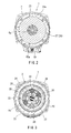
FIG. 2 is a cross-sectional view taken along line II-II inFIG. 1 ; -
FIG. 3 is a cross-sectional view taken along line III-III inFIG. 1 ; -
FIG. 4 is a cross-sectional view of a tool main body when a continuously variable transmission is set at a high velocity rotation through a transmission ring contacting a small diameter region of a planetary roller; -
FIG. 5 is a cross-sectional view of the tool main body when the continuously variable transmission is set at a low velocity rotation through the transmission ring contacting a large-diameter region of the planetary roller; -
FIG. 6 is a view for showing the operation of a control device of the power tool; -
FIG. 7 is a schematic view of a power transmission route of the power tool; -
FIG. 8 is a graph for showing a rotational velocity of a drive motor, a transmission gear ratio of the continuously variable transmission and a rotational output velocity in relation to operational amounts of a switch lever; -
FIG. 9 is a graph for showing the rotational velocity of the drive motor, the transmission gear ratio of the continuously variable transmission and the rotational output velocity in relation to load torque amounts in the condition that the operational amount of the switch lever is maintained constantly; -
FIG. 10 is a graph for showing the rotational velocity of the drive motor, the transmission gear ratio of the continuously variable transmission and the rotational output velocity in relation to load torque amounts in the condition that the operational amount of the switch lever is at its maximum; -
FIG. 11 is a graph for showing efficiencies and output of the drive motor in relation to electric currents supplied to the drive motor; -
FIG. 12 is a graph for showing relationships the gear ratios of the continuously variable transmission and the rotational output velocity when the gear ratios of the continuously variable transmission are shifted from a high velocity state to a low velocity state during an operation; and -
FIG. 13 is a graph for showing relationships between the gear ratios of the continuously variable transmission and the rotational output velocity when a pulling of the switch lever is released while the gear ratios of the continuously variable transmission are shifted from the high velocity state to the low velocity state during operation. - An embodiment of the present invention will be described with reference to
FIGS. 1 to 13 . Apower tool 1 is a rechargeable driver drill. Thepower tool 1 is equipped with a substantially columnar toolmain body 2, ahandle 3 protruding laterally from a side portion of the toolmain body 2, and abattery pack 4 attached to the tip end of thehandle 3. - As shown in
FIG. 1 , the toolmain body 2 is equipped with adrive motor 6, a CVT (continuously variable transmission) 7, agear transmission 8, and aspindle 9, which are arranged inside amain body housing 5 in order from the rear side. Achuck 10 for attaching a tip cutter is provided at the tip end of thespindle 9. The rotational output of thedrive motor 6 is continuously varied by theCVT 7, and is further reduced in velocity at a fixed transmission gear ratio by thegear transmission mechanism 8 before being output to thespindle 9. - As shown in
FIG. 1 , a triggertype switch lever 11, which is pulled with a fingertip of a grasping hand of a user, is arranged near a proximal portion of thehandle 3. When theswitch lever 11 is pulled, a switchmain body 12 on the rear side of theswitch lever 11 is turned on, and thedrive motor 6 is started. A so-called variable switch is used as the switchmain body 12. In the switch, resistance value varies according to a pulling amount of theswitch lever 11, and electric current supplied to thedrive motor 6 is changed. Thus, it is possible to arbitrarily vary the output RPM of thedrive motor 6. - The
drive motor 6 is started using thebattery pack 4 as the power source. Thebattery pack 4 can be repeatedly used by detaching thebattery pack 4 from the tip end of thehandle 3 and charging thebattery pack 4 by a separately prepared charger. - As shown in
FIG. 7 , thegear transmission mechanism 8 is arranged on a front side of the CVT 7 (i.e., on a downstream side in a power transmission route). A planetary gear mechanism is used as thegear transmission mechanism 8.FIGS. 4 and5 show in detail the power transmission route from thedrive motor 6 to thespindle 9. - The
CVT 7 is a three-point press contact type traction drive mechanism, and has a plurality ofplanetary rollers 20. The plurality ofplanetary rollers 20 are supported by asingle holder 24 at equal intervals peripherally. Eachplanetary roller 20 is held in press contact with asun roller 21, apressure roller 22, and atransmission ring 26. - The
sun roller 21 is mounted to anoutput shaft 6a of thedrive motor 6 and rotates integrally therewith. Thepressure roller 22 is held in press contact with a neck portion of eachplanetary roller 20 on the side axially opposite the sun roller 21 (on the downstream side in the power transmission route, i.e., on the right-hand side inFIGS. 4 and5 ). - As shown in
FIG. 4 , anintermediate shaft 30 is arranged coaxially with theoutput shaft 6a of thedrive motor 6. Theholder 24, thepressure roller 22, athrust plate 33, and astationary plate 32 are supported on theintermediate shaft 30. Aboss portion 22a is provided on a rear surface of thepressure roller 22. Theholder 24 is supported by theboss portion 22a so as to allow relative rotation. Acompression spring 34 is provided between thethrust plate 33 and thestationary plate 32. A plurality of cam grooves are formed peripherally in a front surface of thethrust plate 33. A plurality of cam grooves are formed peripherally in the rear surface of thestationary plate 32. Eachsteel ball 41 is installed between each cam groove of thethrust plate 33 and each cam groove of thestationary plate 32. Due to a force in the torque axial direction generated by an urging force of thecompression spring 34 and thesteel balls 41, there is generated press contact force of thesun roller 21, thepressure roller 22, and thetransmission ring 26 with respect to theplanetary rollers 20. - As shown in
FIGS. 3 and4 , thetransmission ring 26 is of an annular configuration. Aconical surface 20a of eachplanetary roller 20 is held in press contact with the inner peripheral surface of thetransmission ring 26. Thetransmission ring 26 is fixed in position so as to extend along the inner surface of aring holder 27. Thering holder 27 is supported so as to be capable of displacement within a fixed range in the axial direction (the horizontal direction in the drawing) with respect to themain body housing 5. When thering holder 27 moves in the axial direction, thetransmission ring 26 moves in the axial direction of the spindle (the horizontal direction as seen inFIGS. 4 and5 ). As a result, thetransmission ring 26 contacts a region between a small diameter region and a large diameter region of theconical surface 20a of eachplanetary roller 20. - As the
sun roller 21 rotates, eachplanetary roller 20 rotates. Eachplanetary roller 20 orbits around thesun roller 21 as theplanetary roller 20 is in press contact with thetransmission ring 26. The orbit direction of eachplanetary roller 20 and the rotational direction of thepressure roller 22 are opposite. Thus, as shown inFIG. 4 , when thetransmission ring 26 contacts the small diameter region of eachplanetary roller 20, the orbiting velocity of theplanetary roller 20 is reduced. As a result, the rotational velocity of thepressure roller 22 is going to be high, and the rotational velocity of theintermediate shaft 30 is going to be high (small transmission gear ratio). As shown inFIG. 5 , when thetransmission ring 26 is displaced to the large diameter region of eachplanetary roller 20, the orbiting velocity of theplanetary roller 20 increases. As a result, the rotational velocity of thepressure ring 22 is going to be low, and the rotational velocity of theintermediate shaft 30 is going to be low (large transmission gear ratio). In this way, the press contact position of thetransmission ring 26 with respect to eachplanetary roller 20 varies, whereby theintermediate shaft 30 is continuously varied in velocity. - As shown in
FIG. 4 , thegear transmission mechanism 8 is connected to a front portion of theintermediate shaft 30. A planetary gear mechanism is used as thegear transmission mechanism 8. Due to thegear transmission mechanism 8, the rotational velocity of theintermediate shaft 30 is reduced at a fixed transmission gear ratio before being output to thespindle 9. - As shown in
FIGS. 4 and5 , thering holder 27 is displaced in the axial direction through the rotation of atransmission sleeve 23 provided in themain body housing 5. When thering holder 27 is displaced in the axial direction, thetransmission ring 26 moves between a position where thetransmission ring 26 contacts the small diameter region of theconical surface 20a of eachplanetary roller 20 and a position where thetransmission ring 26 contacts the large diameter region of theconical surface 20a. - As shown in
FIGS. 4 and5 , atransmission motor 40 is provided near the proximal portion of thehandle 3. Apinion gear 40a is mounted to an output shaft of thetransmission motor 40. Thepinion gear 40a meshes with arack gear portion 23a provided on an outer peripheral surface of atransmission sleeve 23. When thetransmission motor 40 generates normal or reverse rotation, thetransmission sleeve 23 moves through the mesh-engagement between thepinion gear 40a and therack gear portion 23a. Through the movement of thetransmission sleeve 23, thering holder 27 and thetransmission ring 26 are integrally displaced in the axial direction. As a result, thetransmission ring 26 contacts the small diameter region of theconical surface 20a of eachplanetary roller 20 to cause high velocity rotation of theintermediate shaft 30; or thetransmission ring 26 contacts the large diameter region of theconical surface 20a to cause high velocity rotation of theintermediate shaft 30. - As shown in
FIG. 6 , thepower tool 1 is equipped with an operation control device C0 configured to control the RPM of thedrive motor 6 and the transmission gear ratio of theCVT 7. The operation control device C0 is equipped with a drive motor control circuit C1 configured to control the output RPM of thedrive motor 6, and a transmission motor control circuit C2 configured to control the transmission gear ratio of theCVT 7. The transmission motor control circuit C2 changes the transmission gear ratio of theCVT 7 by controlling start/stop timing, rotational direction, and RPM of thetransmission motor 40. - The
power tool 1 is provided with condition detection devices J1 to J3 and J5 configured to detect the condition of thepower tool 1. The first condition detection device J1 detects a pulling amount of theswitch lever 11 based on a change in a variable resistance value of the switchmain body 12. The second condition detection device J2 detects a value of the electric current supplied to thedrive motor 6, and during operation a load torque applied to the tip end tool is detected from the electric current value. The third condition detection device J3 detects a temperature of thedrive motor 6. The fifth condition detection device J5, to which the output signals are input from the first to third condition detection devices, detects changes in each signal with passage of time. The condition detection devices J1 to J3 and J5 transmit signals to the operation control device C0 including information of various conditions. - The condition detection devices J1 to J3 and J5 detect the condition of the
power tool 1, which undergoes various changes due to factors such as the nature of the operation, the proceeding condition thereof, etc. Based on the signal received, the operation control device C0 controls the output RPM of thedrive motor 6 by the drive motor control circuit C1, and controls the transmission gear ratio of theCVT 7 by the transmission motor control circuit C2. In the present embodiment, a device (a fourth detection device) configured to detect the stress condition of each member forming the drive transmission system such as theCVT 7, theintermediate shaft 30, and thespindle 9, is omitted. - In the initial state S0, in which the
switch lever 11 has not been pulled yet, thedrive motor 6 is at rest, so that, as shown inFIG. 8 , the output RPM (right-hand scale) of theintermediate shaft 30 is zero. An initial setting is made such that the transmission gear ratio of theCVT 7 is 1/4 (L0), signifying a low velocity state. - At the stage (S0 to S1), in which the
switch lever 11 has only begun to be pulled and in which the pulling amount is small, the resistance value of the switchmain body 12 is changed according to the pulling amount. As a result, the RPM of thedrive motor 6 increases linearly as indicated by the solid line ofFIG. 8 , and a full velocity state is attained. During this time, thetransmission motor 40 is not started as indicated by the dotted line inFIG. 8 , and the transmission gear ratio of theCVT 7 is maintained at 1/4 (L0). Thus, the RPM of theintermediate shaft 30 increases linear like the RPM of thedrive motor 6, and the RPM of theintermediate shaft 30 is 1/4 of the RPM of thedrive motor 6. - After the RPM of the
drive motor 6 attains the full velocity state (S1), the pulling amount of theswitch lever 11 continues to increase (S1 to S3); then, as indicated by the solid line ofFIG. 8 , thedrive motor 6 is maintained in the full velocity state. At this time, thetransmission motor 40 is started, and thetransmission ring 26 is displaced from the large diameter region to the small diameter region of eachplanetary roller 20. The transmission gear ratio of theCVT 7 is gradually reduced as indicated by the dotted lie inFIG. 8 (It is increased inFIG. 8 ). Thus, the transmission gear ratio of theCVT 7 is reduced while the RPM of thedrive motor 6 is maintained in the full velocity state. Thus, the output RPM of theintermediate shaft 30 increases linearly as the pulling amount of theswitch lever 11 increases. In the totally pulled state (S3), in which theswitch lever 11 has been pulled to the utmost, thedrive motor 6 is in the full velocity state, and a transmission gear ratio of 1/1 is attained in theCVT 7. As a result, theintermediate shaft 30 rotates at the same RPM as thedrive motor 6. Thespindle 9 and the tip cutter are rotated at an RPM reduced by thegear transmission mechanism 8. - Thus, solely through the operation of pulling the
switch lever 11, it is possible to perform both transmission control of thedrive motor 6 and transmission control of theCVT 7. Thus, solely through the operation of theswitch lever 11, it is possible to widely set the RPM of theintermediate shaft 30 and thespindle 9. At the stage where theswitch lever 11 begins to be pulled, high priority is given to the RPM of thedrive motor 6 to increase the same. In the full velocity state (high-output state) of thedrive motor 6, transmission of theCVT 7 is effected. Thus, thepower tool 1 is enhanced in efficiency, and thedrive motor 6 is not easily locked due to over-torque. - As shown in
FIG. 8 , in the case where the pulling amount of theswitch lever 11 is maintained in the half-pulled state S2, the transmission gear ratio of theCVT 7 is 1/1.67 (approximately 60%), and thedrive motor 6 rotates at full velocity. Thus, theintermediate shaft 30 rotates at an RPM that is approximately 60% of the RPM of thedrive motor 6. When a drilling operation or the like is performed while maintaining the half-pulled state S2, there is a change in the external torque (load torque) applied to theintermediate shaft 30 via the tip cutter and thespindle 9. - The double line in
FIG. 9 indicates a change in the RPM of theintermediate shaft 30 with respect to a change in the external torque. The chain double-dashed line inFIG. 9 indicates a comparative example. In the comparative example, thespindle 9 is directly connected with the output shaft of thedrive motor 6. The chain double-dashed line inFIG. 9 indicates the change in the RPM of thedrive motor 6 of the comparative example with respect to the change in external torque. - When the load torque in the second
intermediate shaft 30 increases, the RPM of thedrive motor 6 is reduced linearly (S2 to T1). As indicated by the dashed line inFIG. 9 , in the half-pulled state S2 of theswitch lever 11, thetransmission motor 40 is not started, and the transmission gear ratio of theCVT 7 is maintained at 1.67. Thus, the RPM of theintermediate shaft 30 is also linearly reduced while being maintained at approximately 60% of the RPM of thedrive motor 6. - In the comparative example, over-torque is applied to the
drive motor 6 when the load torque is T1, and the output RPM is reduced to zero. On the other hand, in the present embodiment, the RPM is reduced by theCVT 7, and the torque applied to theintermediate shaft 30 increases. Thus, theintermediate shaft 30 can rotate until the load torque attains T2, which is larger than T1. Thus, it is possible to avoid a stop in the rotation due to over-torque of thedrive motor 6. As a result, the user can perform a drilling operation at a relatively low RPM allowing easy operation with a high motor output. Since it is possible to rotate the drill bit with a high output and at low velocity, it is possible for the user to start the drilling operation carefully and assuredly. - As shown in
FIG. 8 , the operation control device C0 automatically and appropriately controls the RPM of thedrive motor 6 and the transmission gear ratio of theCVT 7 in accordance with the pulling amount of the switch lever 11 (the first and fifth condition detection devices J1 and J5) by a drive motor control circuit C1 and a transmission motor control circuit C2, respectively. More specifically, high priority is given so that the RPM of thedrive motor 6 is increased while maintaining a high transmission gear ratio for theCVT 7. As a result, it is possible to rotate the drill bit with high torque. - As shown in
FIG. 9 , the operation control device C0 automatically switches the control mode when the pulling amount of theswitch lever 11 is fixed to the half-pulled state S2, which corresponds to approximately half of the total operation amount. The second and fifth condition detection devices J2 and J5 detect fluctuations in the load torque during operation. The RPM of thedrive motor 6 is controlled automatically and appropriately by the drive motor control circuit C1. More specifically, when the load torque is received, the transmission gear ratio of theCVT 7 is maintained at a fixed level. As a result, it is possible to perform a drilling operation or the like using the half-pulled state of theswitch lever 11 at low velocity and with high output. It is also possible to suppress locking of thedrive motor 6 by over-torque. As a result, it is possible to perform a drilling operation or the like carefully and assuredly. -
FIG. 10 shows the RPM of thedrive motor 6 and the transmission gear ratio of theCVT 7 when an operation is performed with the switch lever fully pulled (S3 inFIG. 8 ) and with the load torque increased. As the load torque of theintermediate shaft 30 increases (S3 to T3), the RPM of thedrive motor 6 is reduced linearly from the full velocity state. At the stage where the load torque is small (S3 to T3), thetransmission motor 40 is not started, and the transmission gear ratio of theCVT 7 is maintained at 1/1 as indicated by the dashed line inFIG. 10 . Thus, the RPM of theintermediate shaft 30 is the same RPM as the RPM of thedrive motor 6, and is reduced linearly. - As indicated by the dashed line in
FIG. 10 , when the load torque of theintermediate shaft 30 attains a predetermined value (T3), thetransmission motor 40 is started, and thetransmission ring 26 begins to be displaced to the large-diameter region of eachplanetary roller 20. As a result, the transmission gear ratio increases. At the point in time T3, it is possible to maintain an RPM which is somewhat lower than the RPM of thedrive motor 6 in the full velocity state but which is a relatively high RPM. - As indicated by the solid line in
FIG. 10 , at the stage of T3 to T4, it is possible for the RPM of thedrive motor 6 to be maintained at a relatively high RPM. As indicated by the dashed line inFIG. 10 , with the increase in the load torque of theintermediate shaft 30, the transmission gear ratio of theCVT 7 increases linearly from 1/1 to 1/4. When the load torque attains T4, the transmission gear ratio of theCVT 7 is 1/4 at its maximum, and the RPM of theintermediate shaft 30 is 1/4 of the RPM of thedrive motor 6. At this point in time T4, thetransmission motor 40 is stopped, and thetransmission ring 26 is retained in the large-diameter region. As a result, the transmission gear ratio of theCVT 7 is maintained at 1/4, which is the maximum. When the load torque of theintermediate shaft 30 further increases, the RPM of thedrive motor 6 decreases. As a result, the RPM of theintermediate shaft 30 also decreases. - The second condition detection device J2 detects the value of the electric current supplied to the
drive motor 6. In this way, the second condition detection device J2 can obtain the amount of the load torque. When the load torque is in the range of T3 to T4, the drive motor control circuit C1 maintains the RPM of thedrive motor 6 at a relatively high level. The transmission motor control circuit C2 controls thetransmission motor 40 to automatically control the transmission gear ratio of theCVT 7. That is, the transmission gear ratio of theCVT 7 increases with the increase in load torque, and the RPM of theintermediate shaft 30 decreases. As a result, the efficiency of thedrive motor 6 is controlled to an optimum level. -
FIG. 11 illustrates a relationship between the value of the electric current supplied to thedrive motor 6, the motor efficiency (the left-hand scale), and the motor output (the right-hand scale). The solid line inFIG. 11 indicates the change in motor efficiency, and the dashed line indicates the change in motor output. As indicated by the solid line ofFIG. 11 , the motor efficiency of thedrive motor 6 is at its peak within a range of the electric current value (indicated by symbol E inFIG. 11 ), and the motor efficiency is highest when a electric current is supplied. Giving high priority to the electric current value at which the motor efficiency is at its peak, thetransmission motor 40 is controlled, and the transmission gear ratio of theCVT 7 is controlled with the fluctuation in load torque. Thus, in the range of T3 to T4 shown inFIG. 10 , there is executed an eco mode in which high priority is given to motor efficiency. - As indicated by the dashed line in
FIG. 11 , the peak of the output of the drive motor 6 (indicated by symbol P inFIG. 11 ) is in a region where the electric current value is higher than the efficiency value. The electric current value for thedrive motor 6 is detected by the second condition detection device J2, and high priority is given to maintaining the output peak of the electric current value indicated by the dashed line, thus making it possible to control the transmission gear ratio of theCVT 7. As a result, it is possible to execute a power mode in which high priority is given to the motor output. - At the point in time, when the load torque of the
intermediate shaft 30 has been increased to T4 ofFIG. 10 , the transmission gear ratio of theCVT 7 is maintained at a maximum of 1/4. From this point onward, the RPM of thedrive motor 6 is reduced with the increase in load torque, and the RPM of theintermediate shaft 30 is reduced. At the point in time when the load torque of theintermediate shaft 30 is removed with the completion of the operation, the transmission gear ratio of theCVT 7 is maintained at 1/4. - As described above and shown in
FIG. 8 , the operation control device C0 controls both thedrive motor 6 and theCVT 7 according to the pulling amount of theswitch lever 11. At the stage (S0 to S1) where the pulling amount of theswitch lever 11 is small, high priority is given to the motor velocity change. At the stage where the pulling amount is large (S1 to S3), high priority is given to the change of the transmission gear ration of CVT. Thus, it is possible for the user to easily obtain the requisite RPM for the rotary cutter solely through the operation of theswitch lever 11. - Further, as shown in
FIG. 9 , when an operation is performed while maintaining theswitch lever 11 in the half-pulled state S2 the RPM of thedrive motor 6 is controlled with the transmission gear ratio of theCVT 7 maintained at a fixed level. In other words, control is performed so as to maintain a fixed transmission gear ratio for theCVT 7. As a result, thedrive motor 6 is not easily locked due to over-torque. - In the fully pulled state S3 of the
switch lever 11, the second condition detection device J2 detects the motor electric current value. The transmission gear ratio of theCVT 7 is controlled based on the value of the motor electric current. As a result, it is possible to automatically switch between an eco mode in which high priority is given to the motor efficiency and a power mode in which high priority is given to the motor output. -
FIG. 12 illustrates the relationship between the RPM of thedrive motor 6, the transmission gear ratio of theCVT 7, and the RPM of theintermediate shaft 30 as the operation proceeds in the situation where a drilling operation is performed by using thepower tool 1. The range of S0 to S3 ofFIG. 12 coincides with the relationship from the pulling start S0 to the fully pulled state S3 of theswitch lever 11 shown inFIG. 8 . The range of S3 - T3 - T4 - drilling completion inFIG. 12 coincides with the relationship when the load torque fluctuates in the fully pulled state S3 of theswitch lever 11 shown inFIG. 10 . - As shown in
FIG. 12 , in the initial state (S0) in which theswitch lever 11 has not been pulled yet, theintermediate shaft 30 and thespindle 9 are at rest (which means their RPM is zero), and the transmission gear ratio of theCVT 7 is set to 1/4. - In the initial state (S0 to S1) in which the
switch lever 11 has begun to be pulled, thetransmission motor 40 is not started, and the transmission gear ratio of theCVT 7 is maintained at 1/4. The RPM of thedrive motor 6 increases in accordance with the pulling amount of the switch lever 11 (based on the detection by the first condition detection device J1). When the pulling amount of theswitch lever 11 is increased, thetransmission motor 40 starts at the point intime S 1 when thedrive motor 6 has attained the full velocity rotation state, and thetransmission ring 26 begins to be displaced to the small-diameter region of eachplanetary roller 20. As a result, the transmission gear ratio of theCVT 7 is gradually reduced from 1/4 toward 1/1. Thus, even when thedrive motor 6 is maintained in the full velocity state, the RPM of theintermediate shaft 30 continues to increase. - When the
switch lever 11 attains the fully pulled state S3, thetransmission ring 26 is displaced to the small-diameter region of eachplanetary roller 20 by thetransmission motor 40. As a result, the transmission gear ratio of theCVT 7 attains a minimum of 1/1. In the fully pulled state S3, thedrive motor 6 makes full velocity rotation, and theintermediate shaft 30 rotates at maximum velocity. Thereafter, in the stage where the drilling operation proceeds with theswitch lever 11 in the fully pulled state S3, the transmission gear ratio of theCVT 7 is maintained at 1/1. Due to the increase in the load torque of theintermediate shaft 30, the RPM of thedrive motor 6 and of theintermediate shaft 30 is reduced. - The electric current value of the
drive motor 6 is detected by the second condition detection device J2, and it is indirectly detected that the load torque of theintermediate shaft 30 has attained a fixed value based on the electric current value. At the fixed load torque of T3, the control mode is automatically switched from a control mode based on the pulling amount of theswitch lever 11 to a control mode based on the load torque. Thus, from here onward, as described with reference toFIG. 10 , thetransmission motor 40 is started in the reverse direction as the load torque of the intermediate shaft 30 (the electric current value of the drive motor 6) increases, and thetransmission ring 26 begins to be displaced to the large-diameter region of eachplanetary roller 20. As a result, the transmission gear ratio of theCVT 7 gradually increases. - On the other hand, while the transmission gear ratio increases, the RPM of the
drive motor 6 is maintained at a relatively high level. Thus, although the velocity of theintermediate shaft 30 is reduced, there is maintained a state in which the efficiency of thedrive motor 6 is at its highest (within the range indicated by symbol E inFIG. 11 ). A drilling operation is performed in this state. At the point in time T4 when the transmission gear ratio attains a ratio of 1/4 with the increase in the load torque, thetransmission motor 40 stops, and the transmission gear ratio of theCVT 7 begins to be gradually reduced. Thus, the RPM of theintermediate shaft 30 decreases, and the load torque applied to theintermediate shaft 30, i.e., the output torque, gradually increases, and the drilling operation is completed. When, thereafter, the pulling operation on theswitch lever 11 is released, thedrive motor 6 stops. Thus, theintermediate shaft 30 and thespindle 9 stop, and theCVT 7 is maintained at the transmission gear ratio of the initial state, i.e., 1/4. - In the control mode shown in
FIG. 12 , the second condition detection device J2 indirectly detects an increase in the load torque of theintermediate shaft 30, and the transmission gear ratio of theCVT 7 is changed to a maximum of 1/4. After this, the load torque increases, and the RPM of thedrive motor 6 decreases. As a result, the output torque of theintermediate shaft 30 and of thespindle 9 corresponding to the load torque increases until the completion of the drilling. -
FIG. 13 shows a control mode in the situation where the drilling operation is completed at the stage T5. This stage T5 is halfway through the gradual increase in the transmission gear ratio of theCVT 7 from 1/1 to 1/4 with the increase in the load torque of theintermediate shaft 30. The same control mode is adopted in the section S0 to T3 ofFIG. 13 as in the section S0 to T3 ofFIG. 12 . - As shown in
FIG. 13 , when the drilling is completed at the stage T5, which is halfway through the gradual increase in the transmission gear ration of theCVT 7, the load torque of thespindle 9 is reduced in a short period of time. This is detected by the second and fifth condition detection devices J2 and J5. When it is detected at the point in time T5 that the drilling has been completed, the rotational velocity of thetransmission motor 40 increases, and thetransmission ring 26 is displaced to the large-diameter region of eachplanetary roller 20. The transmission gear ratio here is restored to the initial value, i.e., 1/4. When, upon the completion of the drilling, the user releases the pulling operation on theswitch lever 11, and the switchmain body 12 is turned off, the rotation of thedrive motor 6, which has been maintained at a RPM at the stage of T3 to T5, is stopped. Thus, theintermediate shaft 30 and thespindle 9 stop. - As described above and shown in
FIG.6 , thepower tool 1 has the continuouslyvariable transmission 7, the condition detection devices J1 to J3 and J5, and the operation control device C0. The continuouslyvariable transmission 7 changes the rotational output from thedrive motor 6 with respect to the velocity before outputting it to thespindle 9 to which the tip tool is mounted. The condition detection devices J1 to J3 and J5 detect the condition of thepower tool 1. The operation control device C0 determines the target RPM of thespindle 9 based on the condition of thepower tool 1 detected by the condition detection devices J1 to J3 and J5, and controls the RPM of thedrive motor 6 and/or the transmission gear ratio of the continuouslyvariable transmission 7 based on the target RPM. - Thus, as a condition of the
power tool 1, the condition detection devices J1 to J3 and J5 detect the operation amount or operation force applied to the operation member (switch lever 11), the electric current value or temperature of thedrive motor 6, the RPM or output torque of thespindle 9, or a change with passage of time of each condition. Based on this, one or both of the RPM of thedrive motor 6 as well as the transmission gear ratio of the continuouslyvariable transmission 7 are appropriately controlled. Thus, the RPM of thedrive motor 6 and the transmission gear ratio of the continuouslyvariable transmission 7 are controlled automatically and appropriately with a high level of reproducibility in accordance with the operational condition. Thus, it is possible to achieve an improvement in terms of operational efficiency and uniformity. - The
power tool 1 has a plurality of different condition detection devices J1 to J3 and J5. Thus, it is possible to control thepower tool 1 sensitively and in an optimum fashion based on the operational condition of the user and the condition of the power tool. - As the plurality of different condition detection devices, the
power tool 1 is equipped with a device (J1) configured to detect the operational condition of the user, and devices (J2 and J3) configured to detect the condition of the toolmain body 2, which changes with the operation by the user. The operation control device C0 controls the RPM of thedrive motor 6 and/or the transmission gear ratio of the continuouslyvariable transmission 7 based on the operational condition of the user, and controls the condition of the toolmain body 2 at a predetermined, optimum state. - Thus, the
power tool 1 is controlled in an optimum state within a range allowed by the toolmain body 2 with respect to the output required by the user. As a result, it is possible to prevent damage to thepower tool 1 due to the load torque, etc. while maintaining an operational efficiency as high as possible. - The operation control device C0 exhibits a plurality of control patterns with respect to the RPM of the
drive motor 6 and the transmission gear ratio of the continuouslyvariable transmission 7. Based on the condition of thepower tool 1 detected by the condition detection devices J1 to J3 and J5, the operation control device C0 selects one control pattern out of the plurality of control patterns, and controls the RPM of thedrive motor 6 and the transmission gear ratio of the continuouslyvariable transmission 7 by the selected control pattern. - The plurality of control patterns includes a control pattern (eco mode) in which the efficiency of the drive motor is optimized, and a control pattern (power mode) in which the output of the drive motor is optimized. Thus, according to the nature of the operation or the operational stage, the eco mode and the power mode are automatically selected based on the detection by the condition detection devices J1 to J3 and J5. In accordance with the selected control pattern, the RPM of the
drive motor 6 and the transmission gear ratio of the continuouslyvariable transmission 7 are appropriately controlled. Thus, it is possible to improve the operational efficiency. Since the control pattern is automatically selected, the operation can be repeated with a higher level of reproducibility as compared to the situation where the user selects the control pattern. - While the embodiments of invention have been described with reference to specific configurations, it will be apparent to those skilled in the art that many alternatives, modifications and variations may be made without departing from the scope of the present invention. Accordingly, embodiments of the present invention are intended to embrace all such alternatives, modifications and variations that may fall within the spirit and scope of the appended claims. For example, embodiments of the present invention should not be limited to the representative configurations, but may be modified, for example, as described below.
- As shown in
FIG. 6 , it is possible for the condition detection devices J1 to J3 and J5 to be provided in thepower tool 1, or for some other condition detection devices to be provided in as appropriate. For example, instead of or in addition to the condition detection devices J1 to J3 and J5, it is also possible to provide a condition detection device configured to detect the pulling operation force (pressing force) of the operation member, a condition detection device configured to detect the RPM of thedrive motor 6, and a condition detection device configured to detect the RPM and load torque of thespindle 9. - Instead of or in addition to the condition detection devices J1 to J3 and J5, it is also possible to provide a condition detection device configured to detect the switching condition of a normal/reverse switching operation member for switching the rotational direction of the
drive motor 6. Depending on the difference in the rotational direction of thedrive motor 6, it is also possible to perform a different control with respect to the RPM of the drive motor or the transmission gear ratio of theCVT 7. - Instead of or in addition to the condition detection devices J1 to J3 and J5, it is also possible to provide a condition detection device configured to detect the stress condition of the
CVT 7, theintermediate shaft 30, or thespindle 9. For example, it is also possible to detect the deformation amount, pressure, etc. of a member by using a strain gauge and a load cell. - Instead of or in addition to the condition detection devices J1 to J3 and J5, it is also possible to provide a condition detection device configured to detect the electric current value and the temperature at the
battery pack 4. Alternatively, it is also possible to provide a device configured to detect a member wherein the temperature of the member varies in proportion to the load of the motor housing, bearing, etc. or the motor temperature. - As the plurality of different condition detection devices, the
power tool 1 may have at least two of the following condition detection devices: the first condition detection device J1 configured to detect the operational condition of the operation member for starting the drive motor, the second condition detection device J2 configured to detect the electric current value, the third condition detection device J3 configured to detect temperature, the fourth condition detection device J4 configured to detect the stress condition of the drive transmission system, and the fifth condition detection device J5 configured to detect changes with passage of time in the first through fourth condition detection devices. As a result, it is possible to improve the operational efficiency and uniformity. - The
power tool 1 may have thegear transmission mechanism 8 as shown inFIG. 1 ; or it may also have none. - The
power tool 1 may be a rechargeable driver drill as shown inFIG. 1 , or some other electric tool such as a disc grinder or a cutter. Thepower tool 1 may have an electric motor (drive motor 6) as the drive source as shown inFIG. 1 ; or it may also be an air tool having an air motor as the drive source. It is also possible for the air tool to have a condition detection device configured to detect the pressure of the supplied compressed air.
Claims (6)
- A power tool comprising:a continuously variable transmission configured to change a velocity of a rotational output from a drive motor and to output the rotational output to a spindle to which a tip end tool is mounted;a condition detection device is configured to detect a condition of the power tool; andan operation control device configured to determine a target RPM of the spindle based on the condition of the power tool detected by the condition detection device, and to control an RPM of the drive motor and/or a transmission gear ratio of the continuously variable transmission based on the target RPM.
- The power tool of claim 1, wherein the power tool comprises a plurality of different condition detection devices.
- The power tool of claim 2, wherein as the plurality of different condition detection devices, the power tool comprises a device configured to detect an operational condition of a user, and a device configured to detect a condition of a tool main body which changes with an operation by the user, and
wherein the operation control device is configured to control the RPM of the drive motor and/or the transmission gear ratio of the continuously variable transmission based on the operational condition of the user, and control a condition of the tool main body to a predetermined optimum state. - The power tool of claim 2, wherein as the plurality of different condition detection devices, the power tool comprises at least two of the following condition detection devices: a first condition detection device J1 configured to detect an operational condition of the operation member for starting the drive motor, a second condition detection device J2 configured to detect an electric current value, a third condition detection device J3 configured to detect temperature, a fourth condition detection device J4 configured to detect a stress condition of a drive transmission system, and a fifth condition detection device J5 configured to detect changes with passage of time in any of the first to fourth condition detection devices.
- The power tool of any one of claims 1 to 4, wherein the operation control device is configured to exhibit a plurality of control patterns with respect to the RPM of the drive motor and the transmission gear ratio of the continuously variable transmission, the operation control device is configured to select one control pattern out of the plurality of control patterns based on the condition of the power tool detected by the condition detection device, and the operation control device is configured to control the RPM of the drive motor and the transmission gear ratio of the continuously variable transmission by the selected control pattern.
- The power tool of claim 5, wherein the plurality of control patterns includes a control pattern in which an efficiency of the drive motor is optimized, and a control pattern in which the output of the drive motor is optimized.
Applications Claiming Priority (2)
| Application Number | Priority Date | Filing Date | Title |
|---|---|---|---|
| JP2011124056A JP5653843B2 (en) | 2011-06-02 | 2011-06-02 | Power tools |
| PCT/JP2012/061951 WO2012165113A1 (en) | 2011-06-02 | 2012-05-10 | Power tool |
Publications (3)
| Publication Number | Publication Date |
|---|---|
| EP2716407A1 true EP2716407A1 (en) | 2014-04-09 |
| EP2716407A4 EP2716407A4 (en) | 2015-06-17 |
| EP2716407B1 EP2716407B1 (en) | 2017-02-01 |
Family
ID=47258977
Family Applications (1)
| Application Number | Title | Priority Date | Filing Date |
|---|---|---|---|
| EP12792610.3A Not-in-force EP2716407B1 (en) | 2011-06-02 | 2012-05-10 | Power tool |
Country Status (5)
| Country | Link |
|---|---|
| US (1) | US9469023B2 (en) |
| EP (1) | EP2716407B1 (en) |
| JP (1) | JP5653843B2 (en) |
| CN (1) | CN103561913B (en) |
| WO (1) | WO2012165113A1 (en) |
Cited By (1)
| Publication number | Priority date | Publication date | Assignee | Title |
|---|---|---|---|---|
| EP3311958A1 (en) * | 2016-10-21 | 2018-04-25 | Robert Bosch GmbH | Method for regulating a rotational speed of an electric motor of an electric tool |
Families Citing this family (13)
| Publication number | Priority date | Publication date | Assignee | Title |
|---|---|---|---|---|
| JP6383960B2 (en) * | 2013-11-28 | 2018-09-05 | ニューデルタ工業株式会社 | Walking type management machine |
| DE102014208980A1 (en) * | 2014-01-27 | 2015-07-30 | Robert Bosch Gmbh | Machine tool device |
| DE102014209009A1 (en) * | 2014-01-27 | 2015-07-30 | Robert Bosch Gmbh | Machine tool device |
| CN104362910A (en) * | 2014-10-22 | 2015-02-18 | 常州格力博有限公司 | Constant power and double speed control system and control method based on direct current brushless electric tool |
| CN105598503B (en) * | 2016-03-02 | 2018-03-20 | 东莞辰达电器有限公司 | Electric drill |
| JP6480388B2 (en) * | 2016-08-26 | 2019-03-06 | 株式会社スギノマシン | attachment |
| DE102016223678B4 (en) * | 2016-11-29 | 2022-10-13 | Robert Bosch Gmbh | Hand machine tool device |
| DE112018003483B4 (en) | 2017-09-29 | 2021-06-24 | Koki Holdings Co., Ltd. | Electric tool with control unit |
| CN111716554A (en) * | 2019-03-20 | 2020-09-29 | 株式会社吴英制作所 | Punching device |
| JP2020157444A (en) * | 2019-03-27 | 2020-10-01 | オムロン株式会社 | Work tools and control systems equipped with them |
| US20210094139A1 (en) * | 2019-09-30 | 2021-04-01 | Storm Pneumatic Tool Co., Ltd. | Handheld power tool with low speed |
| JP7704580B2 (en) * | 2021-06-10 | 2025-07-08 | 株式会社マキタ | Rotary impact tool |
| US12395044B2 (en) | 2023-02-14 | 2025-08-19 | Hamilton Sundstrand Corporation | CAC motor auxiliary water cooling system |
Family Cites Families (41)
| Publication number | Priority date | Publication date | Assignee | Title |
|---|---|---|---|---|
| DE1938660C3 (en) * | 1969-07-30 | 1975-05-15 | Metabowerke Kg, Closs, Rauch & Schnizler, 7440 Nuertingen | Hammer drill |
| DE6945346U (en) | 1969-11-22 | 1971-04-29 | Bosch Gmbh Robert | ELECTRIC TOOL WITH CONTINUOUSLY ADJUSTABLE SPEED. |
| US4201271A (en) * | 1978-07-10 | 1980-05-06 | Larry Evans | Quill drive with variable feed |
| DE2926111A1 (en) * | 1979-06-28 | 1981-01-08 | Scintilla Ag | ELECTRIC HAND TOOL |
| EP0033353A1 (en) * | 1980-02-05 | 1981-08-12 | Black & Decker Inc. | Method of controlling the speed of a drill, hammer-drill, or rotary hammer and apparatus therefor |
| US4412158A (en) * | 1980-02-21 | 1983-10-25 | Black & Decker Inc. | Speed control circuit for an electric power tool |
| EP0052507B1 (en) * | 1980-11-18 | 1985-02-13 | Black & Decker Inc. | Percussive drills |
| JPH0142692Y2 (en) * | 1984-11-30 | 1989-12-13 | ||
| US4622500A (en) * | 1985-07-11 | 1986-11-11 | The Machlett Laboratories, Inc. | Electric motor controller |
| JPS62255028A (en) | 1986-04-25 | 1987-11-06 | Shimpo Ind Co Ltd | automatic screw tightening machine |
| US4851743A (en) * | 1987-10-27 | 1989-07-25 | Eaton Corporation | DC motor speed controller having protection |
| GB8812292D0 (en) * | 1988-05-24 | 1988-06-29 | Black & Decker Inc | Improvements in/relating to power tools |
| JP2847567B2 (en) | 1989-05-25 | 1999-01-20 | 日立マクセル株式会社 | Magnetic recording media |
| JPH06190740A (en) | 1992-12-22 | 1994-07-12 | Shimpo Ind Co Ltd | Screw driving machine |
| US5986417A (en) * | 1995-04-26 | 1999-11-16 | Sgs-Thomson Mocroelectronics S.A. | Sensorless universal motor speed controller |
| US5738177A (en) * | 1995-07-28 | 1998-04-14 | Black & Decker Inc. | Production assembly tool |
| US6107762A (en) * | 1996-02-06 | 2000-08-22 | S-B Power Tool Company | Speed control device for electrical motor-driven apparatus |
| JPH09314476A (en) * | 1996-05-27 | 1997-12-09 | Black & Decker Inc | Motor-driven tool having motor control circuit for controlling torque output |
| DE19632401A1 (en) * | 1996-08-12 | 1998-02-19 | Delmag Maschinenfabrik | Drill |
| EP0838613B1 (en) | 1996-10-25 | 2002-08-14 | Aisin Aw Co., Ltd. | Infinitely variable transmission |
| JP3376892B2 (en) * | 1996-10-25 | 2003-02-10 | アイシン・エィ・ダブリュ株式会社 | Continuously variable transmission |
| US6536536B1 (en) * | 1999-04-29 | 2003-03-25 | Stephen F. Gass | Power tools |
| CN2409024Y (en) * | 1999-09-01 | 2000-12-06 | 上海星特浩企业有限公司 | Chargeable multipurpose combined tool |
| JP4517456B2 (en) * | 2000-06-08 | 2010-08-04 | ソニー株式会社 | Motor control device |
| JP2002059370A (en) | 2000-08-21 | 2002-02-26 | Fuji Photo Film Co Ltd | Portable torquing device and electric screwdriver |
| AU1386602A (en) * | 2000-09-01 | 2002-03-13 | Black & Decker Incorporated | Optimising method for regulating the operating state of a guided machine tool comprising a rotating percussion tool during a boring process |
| JP2002066960A (en) * | 2000-09-01 | 2002-03-05 | Makita Corp | Power tool |
| US20030089511A1 (en) * | 2001-11-12 | 2003-05-15 | Yukio Tsuneda | Electric tool |
| JP4300840B2 (en) * | 2003-03-26 | 2009-07-22 | パナソニック電工株式会社 | Screw tightening electric tool |
| DE10353302A1 (en) * | 2003-11-11 | 2005-06-09 | C. & E. Fein Gmbh | Electric tool and method for controlling a power tool |
| JP4400519B2 (en) * | 2005-06-30 | 2010-01-20 | パナソニック電工株式会社 | Impact rotary tool |
| US7551411B2 (en) * | 2005-10-12 | 2009-06-23 | Black & Decker Inc. | Control and protection methodologies for a motor control module |
| US7602137B2 (en) * | 2006-02-20 | 2009-10-13 | Black & Decker Inc. | Electronically commutated motor and control system |
| JP5242974B2 (en) * | 2007-08-24 | 2013-07-24 | 株式会社マキタ | Electric tool |
| CN101637906A (en) | 2008-07-31 | 2010-02-03 | 苏州宝时得电动工具有限公司 | Speed changer |
| JP5360344B2 (en) * | 2007-09-21 | 2013-12-04 | 日立工機株式会社 | Electric tool |
| DE102008010136A1 (en) * | 2008-02-20 | 2009-08-27 | Aeg Electric Tools Gmbh | Portable, hand-operated electric machine has working spindle for operating tool, where electric motor operates working spindle by gear arrangement which has automatic transmission for changing transmission ratio |
| JP5112956B2 (en) * | 2008-05-30 | 2013-01-09 | 株式会社マキタ | Rechargeable power tool |
| JP5408535B2 (en) | 2009-07-10 | 2014-02-05 | 日立工機株式会社 | Electric tool |
| US9071188B2 (en) * | 2009-09-04 | 2015-06-30 | Black & Decker Inc. | Protective redundant subsystem for power tools |
| JP5653820B2 (en) | 2011-03-31 | 2015-01-14 | 株式会社マキタ | Power tools |
-
2011
- 2011-06-02 JP JP2011124056A patent/JP5653843B2/en not_active Expired - Fee Related
-
2012
- 2012-05-10 CN CN201280025970.6A patent/CN103561913B/en not_active Expired - Fee Related
- 2012-05-10 EP EP12792610.3A patent/EP2716407B1/en not_active Not-in-force
- 2012-05-10 US US14/114,548 patent/US9469023B2/en not_active Expired - Fee Related
- 2012-05-10 WO PCT/JP2012/061951 patent/WO2012165113A1/en not_active Ceased
Cited By (2)
| Publication number | Priority date | Publication date | Assignee | Title |
|---|---|---|---|---|
| EP3311958A1 (en) * | 2016-10-21 | 2018-04-25 | Robert Bosch GmbH | Method for regulating a rotational speed of an electric motor of an electric tool |
| US10333441B2 (en) | 2016-10-21 | 2019-06-25 | Robert Bosch Gmbh | Method for regulating a speed of an electric motor of a power tool |
Also Published As
| Publication number | Publication date |
|---|---|
| US9469023B2 (en) | 2016-10-18 |
| EP2716407A4 (en) | 2015-06-17 |
| JP2012250308A (en) | 2012-12-20 |
| WO2012165113A1 (en) | 2012-12-06 |
| CN103561913A (en) | 2014-02-05 |
| CN103561913B (en) | 2015-11-25 |
| US20140374131A1 (en) | 2014-12-25 |
| EP2716407B1 (en) | 2017-02-01 |
| JP5653843B2 (en) | 2015-01-14 |
Similar Documents
| Publication | Publication Date | Title |
|---|---|---|
| EP2716407B1 (en) | Power tool | |
| US8485275B2 (en) | Power tool | |
| JP5899471B2 (en) | Electric tool | |
| EP2394797B1 (en) | Power tool | |
| EP2110921B1 (en) | Battery management system for a cordless tool | |
| JP5974616B2 (en) | Electric tool | |
| EP2529895A1 (en) | Power tool | |
| US20170274963A1 (en) | Drive unit for bicycle | |
| AU2005229696A1 (en) | Mode selector mechanism for an impact driver | |
| US10099353B2 (en) | Nut-fastening tool | |
| US11858105B2 (en) | Power tool and torque-responsive gear unit for a power tool | |
| GB2476372A (en) | Torque coupling with axially displaceable ring gear | |
| US10751869B2 (en) | Speed-changing tool | |
| US20120255755A1 (en) | Power tool | |
| JP5493272B2 (en) | Rotary impact tool | |
| JP5262559B2 (en) | Continuously variable transmission | |
| JP2002066960A (en) | Power tool | |
| CN113692333A (en) | Screw fastening tool | |
| EP2724823B1 (en) | Power tool | |
| WO2023110230A1 (en) | Power tool and load-responsive power transmission for a power tool | |
| JP5620338B2 (en) | Power tools | |
| JP2019141945A (en) | Screwing tool | |
| JP2011179567A (en) | Belt type continuously variable transmission | |
| JP5963050B2 (en) | Impact rotary tool | |
| CN223120591U (en) | Gear shifting mechanism and transmission |
Legal Events
| Date | Code | Title | Description |
|---|---|---|---|
| PUAI | Public reference made under article 153(3) epc to a published international application that has entered the european phase |
Free format text: ORIGINAL CODE: 0009012 |
|
| 17P | Request for examination filed |
Effective date: 20131107 |
|
| AK | Designated contracting states |
Kind code of ref document: A1 Designated state(s): AL AT BE BG CH CY CZ DE DK EE ES FI FR GB GR HR HU IE IS IT LI LT LU LV MC MK MT NL NO PL PT RO RS SE SI SK SM TR |
|
| DAX | Request for extension of the european patent (deleted) | ||
| RA4 | Supplementary search report drawn up and despatched (corrected) |
Effective date: 20150519 |
|
| RIC1 | Information provided on ipc code assigned before grant |
Ipc: F16H 15/50 20060101ALI20150512BHEP Ipc: B23P 19/06 20060101ALI20150512BHEP Ipc: B23B 45/02 20060101ALI20150512BHEP Ipc: B25B 23/14 20060101AFI20150512BHEP Ipc: B25F 5/00 20060101ALI20150512BHEP Ipc: B25B 21/00 20060101ALI20150512BHEP Ipc: B25B 23/147 20060101ALI20150512BHEP |
|
| GRAP | Despatch of communication of intention to grant a patent |
Free format text: ORIGINAL CODE: EPIDOSNIGR1 |
|
| INTG | Intention to grant announced |
Effective date: 20160819 |
|
| GRAS | Grant fee paid |
Free format text: ORIGINAL CODE: EPIDOSNIGR3 |
|
| GRAJ | Information related to disapproval of communication of intention to grant by the applicant or resumption of examination proceedings by the epo deleted |
Free format text: ORIGINAL CODE: EPIDOSDIGR1 |
|
| GRAL | Information related to payment of fee for publishing/printing deleted |
Free format text: ORIGINAL CODE: EPIDOSDIGR3 |
|
| GRAR | Information related to intention to grant a patent recorded |
Free format text: ORIGINAL CODE: EPIDOSNIGR71 |
|
| GRAA | (expected) grant |
Free format text: ORIGINAL CODE: 0009210 |
|
| INTC | Intention to grant announced (deleted) | ||
| INTG | Intention to grant announced |
Effective date: 20161222 |
|
| AK | Designated contracting states |
Kind code of ref document: B1 Designated state(s): AL AT BE BG CH CY CZ DE DK EE ES FI FR GB GR HR HU IE IS IT LI LT LU LV MC MK MT NL NO PL PT RO RS SE SI SK SM TR |
|
| REG | Reference to a national code |
Ref country code: GB Ref legal event code: FG4D |
|
| REG | Reference to a national code |
Ref country code: CH Ref legal event code: EP Ref country code: AT Ref legal event code: REF Ref document number: 865149 Country of ref document: AT Kind code of ref document: T Effective date: 20170215 |
|
| REG | Reference to a national code |
Ref country code: IE Ref legal event code: FG4D |
|
| REG | Reference to a national code |
Ref country code: DE Ref legal event code: R096 Ref document number: 602012028354 Country of ref document: DE |
|
| REG | Reference to a national code |
Ref country code: FR Ref legal event code: PLFP Year of fee payment: 6 |
|
| REG | Reference to a national code |
Ref country code: NL Ref legal event code: MP Effective date: 20170201 |
|
| REG | Reference to a national code |
Ref country code: LT Ref legal event code: MG4D |
|
| REG | Reference to a national code |
Ref country code: AT Ref legal event code: MK05 Ref document number: 865149 Country of ref document: AT Kind code of ref document: T Effective date: 20170201 |
|
| PG25 | Lapsed in a contracting state [announced via postgrant information from national office to epo] |
Ref country code: FI Free format text: LAPSE BECAUSE OF FAILURE TO SUBMIT A TRANSLATION OF THE DESCRIPTION OR TO PAY THE FEE WITHIN THE PRESCRIBED TIME-LIMIT Effective date: 20170201 Ref country code: IS Free format text: LAPSE BECAUSE OF FAILURE TO SUBMIT A TRANSLATION OF THE DESCRIPTION OR TO PAY THE FEE WITHIN THE PRESCRIBED TIME-LIMIT Effective date: 20170601 Ref country code: NO Free format text: LAPSE BECAUSE OF FAILURE TO SUBMIT A TRANSLATION OF THE DESCRIPTION OR TO PAY THE FEE WITHIN THE PRESCRIBED TIME-LIMIT Effective date: 20170501 Ref country code: HR Free format text: LAPSE BECAUSE OF FAILURE TO SUBMIT A TRANSLATION OF THE DESCRIPTION OR TO PAY THE FEE WITHIN THE PRESCRIBED TIME-LIMIT Effective date: 20170201 Ref country code: LT Free format text: LAPSE BECAUSE OF FAILURE TO SUBMIT A TRANSLATION OF THE DESCRIPTION OR TO PAY THE FEE WITHIN THE PRESCRIBED TIME-LIMIT Effective date: 20170201 Ref country code: GR Free format text: LAPSE BECAUSE OF FAILURE TO SUBMIT A TRANSLATION OF THE DESCRIPTION OR TO PAY THE FEE WITHIN THE PRESCRIBED TIME-LIMIT Effective date: 20170502 |
|
| PG25 | Lapsed in a contracting state [announced via postgrant information from national office to epo] |
Ref country code: ES Free format text: LAPSE BECAUSE OF FAILURE TO SUBMIT A TRANSLATION OF THE DESCRIPTION OR TO PAY THE FEE WITHIN THE PRESCRIBED TIME-LIMIT Effective date: 20170201 Ref country code: BG Free format text: LAPSE BECAUSE OF FAILURE TO SUBMIT A TRANSLATION OF THE DESCRIPTION OR TO PAY THE FEE WITHIN THE PRESCRIBED TIME-LIMIT Effective date: 20170501 Ref country code: PT Free format text: LAPSE BECAUSE OF FAILURE TO SUBMIT A TRANSLATION OF THE DESCRIPTION OR TO PAY THE FEE WITHIN THE PRESCRIBED TIME-LIMIT Effective date: 20170601 Ref country code: LU Free format text: LAPSE BECAUSE OF NON-PAYMENT OF DUE FEES Effective date: 20170531 Ref country code: PL Free format text: LAPSE BECAUSE OF FAILURE TO SUBMIT A TRANSLATION OF THE DESCRIPTION OR TO PAY THE FEE WITHIN THE PRESCRIBED TIME-LIMIT Effective date: 20170201 Ref country code: RS Free format text: LAPSE BECAUSE OF FAILURE TO SUBMIT A TRANSLATION OF THE DESCRIPTION OR TO PAY THE FEE WITHIN THE PRESCRIBED TIME-LIMIT Effective date: 20170201 Ref country code: SE Free format text: LAPSE BECAUSE OF FAILURE TO SUBMIT A TRANSLATION OF THE DESCRIPTION OR TO PAY THE FEE WITHIN THE PRESCRIBED TIME-LIMIT Effective date: 20170201 Ref country code: NL Free format text: LAPSE BECAUSE OF FAILURE TO SUBMIT A TRANSLATION OF THE DESCRIPTION OR TO PAY THE FEE WITHIN THE PRESCRIBED TIME-LIMIT Effective date: 20170201 Ref country code: LV Free format text: LAPSE BECAUSE OF FAILURE TO SUBMIT A TRANSLATION OF THE DESCRIPTION OR TO PAY THE FEE WITHIN THE PRESCRIBED TIME-LIMIT Effective date: 20170201 Ref country code: AT Free format text: LAPSE BECAUSE OF FAILURE TO SUBMIT A TRANSLATION OF THE DESCRIPTION OR TO PAY THE FEE WITHIN THE PRESCRIBED TIME-LIMIT Effective date: 20170201 |
|
| PG25 | Lapsed in a contracting state [announced via postgrant information from national office to epo] |
Ref country code: EE Free format text: LAPSE BECAUSE OF FAILURE TO SUBMIT A TRANSLATION OF THE DESCRIPTION OR TO PAY THE FEE WITHIN THE PRESCRIBED TIME-LIMIT Effective date: 20170201 Ref country code: IT Free format text: LAPSE BECAUSE OF FAILURE TO SUBMIT A TRANSLATION OF THE DESCRIPTION OR TO PAY THE FEE WITHIN THE PRESCRIBED TIME-LIMIT Effective date: 20170201 Ref country code: RO Free format text: LAPSE BECAUSE OF FAILURE TO SUBMIT A TRANSLATION OF THE DESCRIPTION OR TO PAY THE FEE WITHIN THE PRESCRIBED TIME-LIMIT Effective date: 20170201 Ref country code: CZ Free format text: LAPSE BECAUSE OF FAILURE TO SUBMIT A TRANSLATION OF THE DESCRIPTION OR TO PAY THE FEE WITHIN THE PRESCRIBED TIME-LIMIT Effective date: 20170201 Ref country code: SK Free format text: LAPSE BECAUSE OF FAILURE TO SUBMIT A TRANSLATION OF THE DESCRIPTION OR TO PAY THE FEE WITHIN THE PRESCRIBED TIME-LIMIT Effective date: 20170201 |
|
| REG | Reference to a national code |
Ref country code: DE Ref legal event code: R097 Ref document number: 602012028354 Country of ref document: DE |
|
| PG25 | Lapsed in a contracting state [announced via postgrant information from national office to epo] |
Ref country code: SM Free format text: LAPSE BECAUSE OF FAILURE TO SUBMIT A TRANSLATION OF THE DESCRIPTION OR TO PAY THE FEE WITHIN THE PRESCRIBED TIME-LIMIT Effective date: 20170201 Ref country code: DK Free format text: LAPSE BECAUSE OF FAILURE TO SUBMIT A TRANSLATION OF THE DESCRIPTION OR TO PAY THE FEE WITHIN THE PRESCRIBED TIME-LIMIT Effective date: 20170201 |
|
| PLBE | No opposition filed within time limit |
Free format text: ORIGINAL CODE: 0009261 |
|
| STAA | Information on the status of an ep patent application or granted ep patent |
Free format text: STATUS: NO OPPOSITION FILED WITHIN TIME LIMIT |
|
| REG | Reference to a national code |
Ref country code: CH Ref legal event code: PL |
|
| 26N | No opposition filed |
Effective date: 20171103 |
|
| PG25 | Lapsed in a contracting state [announced via postgrant information from national office to epo] |
Ref country code: MC Free format text: LAPSE BECAUSE OF FAILURE TO SUBMIT A TRANSLATION OF THE DESCRIPTION OR TO PAY THE FEE WITHIN THE PRESCRIBED TIME-LIMIT Effective date: 20170201 |
|
| REG | Reference to a national code |
Ref country code: IE Ref legal event code: MM4A |
|
| PG25 | Lapsed in a contracting state [announced via postgrant information from national office to epo] |
Ref country code: CH Free format text: LAPSE BECAUSE OF NON-PAYMENT OF DUE FEES Effective date: 20170531 Ref country code: LI Free format text: LAPSE BECAUSE OF NON-PAYMENT OF DUE FEES Effective date: 20170531 Ref country code: SI Free format text: LAPSE BECAUSE OF FAILURE TO SUBMIT A TRANSLATION OF THE DESCRIPTION OR TO PAY THE FEE WITHIN THE PRESCRIBED TIME-LIMIT Effective date: 20170201 |
|
| PG25 | Lapsed in a contracting state [announced via postgrant information from national office to epo] |
Ref country code: LU Free format text: LAPSE BECAUSE OF NON-PAYMENT OF DUE FEES Effective date: 20170510 |
|
| REG | Reference to a national code |
Ref country code: FR Ref legal event code: PLFP Year of fee payment: 7 |
|
| REG | Reference to a national code |
Ref country code: BE Ref legal event code: MM Effective date: 20170531 |
|
| PG25 | Lapsed in a contracting state [announced via postgrant information from national office to epo] |
Ref country code: IE Free format text: LAPSE BECAUSE OF NON-PAYMENT OF DUE FEES Effective date: 20170510 |
|
| PG25 | Lapsed in a contracting state [announced via postgrant information from national office to epo] |
Ref country code: BE Free format text: LAPSE BECAUSE OF NON-PAYMENT OF DUE FEES Effective date: 20170531 |
|
| PG25 | Lapsed in a contracting state [announced via postgrant information from national office to epo] |
Ref country code: MT Free format text: LAPSE BECAUSE OF NON-PAYMENT OF DUE FEES Effective date: 20170510 |
|
| PG25 | Lapsed in a contracting state [announced via postgrant information from national office to epo] |
Ref country code: HU Free format text: LAPSE BECAUSE OF FAILURE TO SUBMIT A TRANSLATION OF THE DESCRIPTION OR TO PAY THE FEE WITHIN THE PRESCRIBED TIME-LIMIT; INVALID AB INITIO Effective date: 20120510 |
|
| PGFP | Annual fee paid to national office [announced via postgrant information from national office to epo] |
Ref country code: DE Payment date: 20190430 Year of fee payment: 8 |
|
| PGFP | Annual fee paid to national office [announced via postgrant information from national office to epo] |
Ref country code: FR Payment date: 20190410 Year of fee payment: 8 |
|
| PG25 | Lapsed in a contracting state [announced via postgrant information from national office to epo] |
Ref country code: CY Free format text: LAPSE BECAUSE OF NON-PAYMENT OF DUE FEES Effective date: 20170201 |
|
| PGFP | Annual fee paid to national office [announced via postgrant information from national office to epo] |
Ref country code: GB Payment date: 20190508 Year of fee payment: 8 |
|
| PG25 | Lapsed in a contracting state [announced via postgrant information from national office to epo] |
Ref country code: MK Free format text: LAPSE BECAUSE OF FAILURE TO SUBMIT A TRANSLATION OF THE DESCRIPTION OR TO PAY THE FEE WITHIN THE PRESCRIBED TIME-LIMIT Effective date: 20170201 |
|
| PG25 | Lapsed in a contracting state [announced via postgrant information from national office to epo] |
Ref country code: TR Free format text: LAPSE BECAUSE OF FAILURE TO SUBMIT A TRANSLATION OF THE DESCRIPTION OR TO PAY THE FEE WITHIN THE PRESCRIBED TIME-LIMIT Effective date: 20170201 |
|
| PG25 | Lapsed in a contracting state [announced via postgrant information from national office to epo] |
Ref country code: AL Free format text: LAPSE BECAUSE OF FAILURE TO SUBMIT A TRANSLATION OF THE DESCRIPTION OR TO PAY THE FEE WITHIN THE PRESCRIBED TIME-LIMIT Effective date: 20170201 |
|
| REG | Reference to a national code |
Ref country code: DE Ref legal event code: R119 Ref document number: 602012028354 Country of ref document: DE |
|
| GBPC | Gb: european patent ceased through non-payment of renewal fee |
Effective date: 20200510 |
|
| PG25 | Lapsed in a contracting state [announced via postgrant information from national office to epo] |
Ref country code: GB Free format text: LAPSE BECAUSE OF NON-PAYMENT OF DUE FEES Effective date: 20200510 Ref country code: FR Free format text: LAPSE BECAUSE OF NON-PAYMENT OF DUE FEES Effective date: 20200531 |
|
| PG25 | Lapsed in a contracting state [announced via postgrant information from national office to epo] |
Ref country code: DE Free format text: LAPSE BECAUSE OF NON-PAYMENT OF DUE FEES Effective date: 20201201 |