EP2715298B1 - Method for buffering thermal energy and thermal energy buffer system - Google Patents
Method for buffering thermal energy and thermal energy buffer system Download PDFInfo
- Publication number
- EP2715298B1 EP2715298B1 EP12729056.7A EP12729056A EP2715298B1 EP 2715298 B1 EP2715298 B1 EP 2715298B1 EP 12729056 A EP12729056 A EP 12729056A EP 2715298 B1 EP2715298 B1 EP 2715298B1
- Authority
- EP
- European Patent Office
- Prior art keywords
- thermal energy
- thermal
- temperature
- amount
- buffer
- Prior art date
- Legal status (The legal status is an assumption and is not a legal conclusion. Google has not performed a legal analysis and makes no representation as to the accuracy of the status listed.)
- Not-in-force
Links
Images


Classifications
-
- F—MECHANICAL ENGINEERING; LIGHTING; HEATING; WEAPONS; BLASTING
- F24—HEATING; RANGES; VENTILATING
- F24H—FLUID HEATERS, e.g. WATER OR AIR HEATERS, HAVING HEAT-GENERATING MEANS, e.g. HEAT PUMPS, IN GENERAL
- F24H9/00—Details
- F24H9/20—Arrangement or mounting of control or safety devices
- F24H9/2007—Arrangement or mounting of control or safety devices for water heaters
- F24H9/2014—Arrangement or mounting of control or safety devices for water heaters using electrical energy supply
-
- F—MECHANICAL ENGINEERING; LIGHTING; HEATING; WEAPONS; BLASTING
- F24—HEATING; RANGES; VENTILATING
- F24D—DOMESTIC- OR SPACE-HEATING SYSTEMS, e.g. CENTRAL HEATING SYSTEMS; DOMESTIC HOT-WATER SUPPLY SYSTEMS; ELEMENTS OR COMPONENTS THEREFOR
- F24D19/00—Details
- F24D19/10—Arrangement or mounting of control or safety devices
- F24D19/1006—Arrangement or mounting of control or safety devices for water heating systems
- F24D19/1051—Arrangement or mounting of control or safety devices for water heating systems for domestic hot water
- F24D19/1063—Arrangement or mounting of control or safety devices for water heating systems for domestic hot water counting of energy consumption
-
- F—MECHANICAL ENGINEERING; LIGHTING; HEATING; WEAPONS; BLASTING
- F24—HEATING; RANGES; VENTILATING
- F24H—FLUID HEATERS, e.g. WATER OR AIR HEATERS, HAVING HEAT-GENERATING MEANS, e.g. HEAT PUMPS, IN GENERAL
- F24H15/00—Control of fluid heaters
- F24H15/10—Control of fluid heaters characterised by the purpose of the control
- F24H15/144—Measuring or calculating energy consumption
-
- F—MECHANICAL ENGINEERING; LIGHTING; HEATING; WEAPONS; BLASTING
- F24—HEATING; RANGES; VENTILATING
- F24H—FLUID HEATERS, e.g. WATER OR AIR HEATERS, HAVING HEAT-GENERATING MEANS, e.g. HEAT PUMPS, IN GENERAL
- F24H15/00—Control of fluid heaters
- F24H15/20—Control of fluid heaters characterised by control inputs
- F24H15/212—Temperature of the water
- F24H15/223—Temperature of the water in the water storage tank
- F24H15/225—Temperature of the water in the water storage tank at different heights of the tank
-
- F—MECHANICAL ENGINEERING; LIGHTING; HEATING; WEAPONS; BLASTING
- F24—HEATING; RANGES; VENTILATING
- F24H—FLUID HEATERS, e.g. WATER OR AIR HEATERS, HAVING HEAT-GENERATING MEANS, e.g. HEAT PUMPS, IN GENERAL
- F24H15/00—Control of fluid heaters
- F24H15/40—Control of fluid heaters characterised by the type of controllers
- F24H15/414—Control of fluid heaters characterised by the type of controllers using electronic processing, e.g. computer-based
- F24H15/45—Control of fluid heaters characterised by the type of controllers using electronic processing, e.g. computer-based remotely accessible
-
- F—MECHANICAL ENGINEERING; LIGHTING; HEATING; WEAPONS; BLASTING
- F24—HEATING; RANGES; VENTILATING
- F24H—FLUID HEATERS, e.g. WATER OR AIR HEATERS, HAVING HEAT-GENERATING MEANS, e.g. HEAT PUMPS, IN GENERAL
- F24H9/00—Details
- F24H9/20—Arrangement or mounting of control or safety devices
- F24H9/2007—Arrangement or mounting of control or safety devices for water heaters
- F24H9/2014—Arrangement or mounting of control or safety devices for water heaters using electrical energy supply
- F24H9/2021—Storage heaters
-
- F—MECHANICAL ENGINEERING; LIGHTING; HEATING; WEAPONS; BLASTING
- F28—HEAT EXCHANGE IN GENERAL
- F28D—HEAT-EXCHANGE APPARATUS, NOT PROVIDED FOR IN ANOTHER SUBCLASS, IN WHICH THE HEAT-EXCHANGE MEDIA DO NOT COME INTO DIRECT CONTACT
- F28D20/00—Heat storage plants or apparatus in general; Regenerative heat-exchange apparatus not covered by groups F28D17/00 or F28D19/00
- F28D20/0034—Heat storage plants or apparatus in general; Regenerative heat-exchange apparatus not covered by groups F28D17/00 or F28D19/00 using liquid heat storage material
- F28D20/0039—Heat storage plants or apparatus in general; Regenerative heat-exchange apparatus not covered by groups F28D17/00 or F28D19/00 using liquid heat storage material with stratification of the heat storage material
-
- F—MECHANICAL ENGINEERING; LIGHTING; HEATING; WEAPONS; BLASTING
- F28—HEAT EXCHANGE IN GENERAL
- F28F—DETAILS OF HEAT-EXCHANGE AND HEAT-TRANSFER APPARATUS, OF GENERAL APPLICATION
- F28F27/00—Control arrangements or safety devices specially adapted for heat-exchange or heat-transfer apparatus
-
- G—PHYSICS
- G01—MEASURING; TESTING
- G01K—MEASURING TEMPERATURE; MEASURING QUANTITY OF HEAT; THERMALLY-SENSITIVE ELEMENTS NOT OTHERWISE PROVIDED FOR
- G01K17/00—Measuring quantity of heat
-
- G—PHYSICS
- G01—MEASURING; TESTING
- G01K—MEASURING TEMPERATURE; MEASURING QUANTITY OF HEAT; THERMALLY-SENSITIVE ELEMENTS NOT OTHERWISE PROVIDED FOR
- G01K17/00—Measuring quantity of heat
- G01K17/06—Measuring quantity of heat conveyed by flowing media, e.g. in heating systems e.g. the quantity of heat in a transporting medium, delivered to or consumed in an expenditure device
-
- G—PHYSICS
- G05—CONTROLLING; REGULATING
- G05D—SYSTEMS FOR CONTROLLING OR REGULATING NON-ELECTRIC VARIABLES
- G05D23/00—Control of temperature
- G05D23/19—Control of temperature characterised by the use of electric means
- G05D23/1919—Control of temperature characterised by the use of electric means characterised by the type of controller
- G05D23/1923—Control of temperature characterised by the use of electric means characterised by the type of controller using thermal energy, the cost of which varies in function of time
-
- G—PHYSICS
- G05—CONTROLLING; REGULATING
- G05D—SYSTEMS FOR CONTROLLING OR REGULATING NON-ELECTRIC VARIABLES
- G05D23/00—Control of temperature
- G05D23/19—Control of temperature characterised by the use of electric means
- G05D23/1927—Control of temperature characterised by the use of electric means using a plurality of sensors
- G05D23/193—Control of temperature characterised by the use of electric means using a plurality of sensors sensing the temperaure in different places in thermal relationship with one or more spaces
- G05D23/1931—Control of temperature characterised by the use of electric means using a plurality of sensors sensing the temperaure in different places in thermal relationship with one or more spaces to control the temperature of one space
-
- F—MECHANICAL ENGINEERING; LIGHTING; HEATING; WEAPONS; BLASTING
- F24—HEATING; RANGES; VENTILATING
- F24D—DOMESTIC- OR SPACE-HEATING SYSTEMS, e.g. CENTRAL HEATING SYSTEMS; DOMESTIC HOT-WATER SUPPLY SYSTEMS; ELEMENTS OR COMPONENTS THEREFOR
- F24D2240/00—Characterizing positions, e.g. of sensors, inlets, outlets
- F24D2240/26—Vertically distributed at fixed positions, e.g. multiple sensors distributed over the height of a tank, or a vertical inlet distribution pipe having a plurality of orifices
-
- F—MECHANICAL ENGINEERING; LIGHTING; HEATING; WEAPONS; BLASTING
- F24—HEATING; RANGES; VENTILATING
- F24H—FLUID HEATERS, e.g. WATER OR AIR HEATERS, HAVING HEAT-GENERATING MEANS, e.g. HEAT PUMPS, IN GENERAL
- F24H15/00—Control of fluid heaters
- F24H15/20—Control of fluid heaters characterised by control inputs
- F24H15/281—Input from user
-
- F—MECHANICAL ENGINEERING; LIGHTING; HEATING; WEAPONS; BLASTING
- F24—HEATING; RANGES; VENTILATING
- F24H—FLUID HEATERS, e.g. WATER OR AIR HEATERS, HAVING HEAT-GENERATING MEANS, e.g. HEAT PUMPS, IN GENERAL
- F24H15/00—Control of fluid heaters
- F24H15/30—Control of fluid heaters characterised by control outputs; characterised by the components to be controlled
- F24H15/395—Information to users, e.g. alarms
-
- F—MECHANICAL ENGINEERING; LIGHTING; HEATING; WEAPONS; BLASTING
- F28—HEAT EXCHANGE IN GENERAL
- F28D—HEAT-EXCHANGE APPARATUS, NOT PROVIDED FOR IN ANOTHER SUBCLASS, IN WHICH THE HEAT-EXCHANGE MEDIA DO NOT COME INTO DIRECT CONTACT
- F28D20/00—Heat storage plants or apparatus in general; Regenerative heat-exchange apparatus not covered by groups F28D17/00 or F28D19/00
- F28D2020/0065—Details, e.g. particular heat storage tanks, auxiliary members within tanks
- F28D2020/0078—Heat exchanger arrangements
-
- Y—GENERAL TAGGING OF NEW TECHNOLOGICAL DEVELOPMENTS; GENERAL TAGGING OF CROSS-SECTIONAL TECHNOLOGIES SPANNING OVER SEVERAL SECTIONS OF THE IPC; TECHNICAL SUBJECTS COVERED BY FORMER USPC CROSS-REFERENCE ART COLLECTIONS [XRACs] AND DIGESTS
- Y02—TECHNOLOGIES OR APPLICATIONS FOR MITIGATION OR ADAPTATION AGAINST CLIMATE CHANGE
- Y02E—REDUCTION OF GREENHOUSE GAS [GHG] EMISSIONS, RELATED TO ENERGY GENERATION, TRANSMISSION OR DISTRIBUTION
- Y02E60/00—Enabling technologies; Technologies with a potential or indirect contribution to GHG emissions mitigation
- Y02E60/14—Thermal energy storage
Definitions
- the current invention relates to a method for buffering thermal energy according to the preamble of the first claim.
- the present invention also relates to a thermal energy buffer system for buffering thermal energy.
- the present invention also relates to software for executing the method or for implementing the above system.
- thermal energy buffer is for example a water heating unit of a domestic hot water system.
- a thermal energy buffer contains a thermal buffering medium, often water, contained in a tank and a controller controlling a heater of the thermal buffer.
- the heater can for example be an electrical heater provided at the bottom of the tank. In such water heating units, water often enters the tank at the bottom of the tank and exits the tank at the top.
- the controller is provided to receive a signal representing three signals representing thermal energy values related to the thermal energy buffer.
- the minimum temperature represents the predetermined minimum amount of energy present in the thermal energy buffer.
- JP9068369 , JP2004218873 , WO88/05160 , EP2146309 and US2005/019631 are examples of known methods and systems for buffering thermal energy in a thermal buffering medium.
- the controller calculates values representing amounts of thermal energy, comprising a minimal amount of heating energy representing the amount of energy (E min ) required to, using the heater, heat all the thermal buffering medium to a predetermined minimum temperature starting from the amount of thermal energy present in the thermal energy buffer.
- the predetermined minimum temperature is preferably the preferred minimum temperature at which water leaves the thermal energy buffer.
- the thermal energy values comprise also a maximal amount of heating energy (E max ) representing the amount of energy required to, using the heater, heat all the thermal buffering medium to a predetermined maximum temperature starting from the amount of thermal energy present in the thermal energy buffer.
- the controller calculates the amount of thermal energy present in the thermal energy buffer by dividing the value representing the amount of thermal energy present in the thermal energy buffer with the value representing the maximum amount of thermal energy stored in the thermal energy buffer.
- the value is the State of Charge (SoC).
- SoC State of Charge
- the controller calculates SOC, i.e. the amount of thermal energy present in the thermal energy buffer by dividing the value representing the amount of thermal energy present in the thermal energy buffer with the total volume of the thermal buffering medium multiplied with the difference between the predetermined minimum and maximum temperature.
- another value calculated by the controller is the total amount, of thermal energy present in the thermal energy buffer, said value being the sum of values each representing the thermal energy measured for a different part of the thermal buffering medium and each calculated by multiplying the temperature measured by the sensor of at least one part of the thermal buffering medium with the volume of the part of thermal buffering medium such as to obtain at least one value representing the partial thermal energy contained in the at least one part by the thermal buffering medium.
- Such a calculated thermal energy value next to taking into account the temperature of the volume of thermal buffering medium, such as for example water, also takes into account the volume itself of the thermal buffering medium such that a better representation of the energy content of the thermal buffering medium is obtained.
- Such an energy content can then be used to represent the thermal energy values and it has been found that, for example, thermal energy values represented in this way can be successfully used to control completely different thermal energy buffers with a single controller.
- thermo energy buffer can be used in a smart grid control system such as for example the method described in the European patent application EP11162735.2 .
- Embodiments of the present invention can provide one or more advantageous technical solutions:
- the thermal energy buffer is a water heating unit of a domestic hot water system.
- the thermal buffering medium is water.
- the controller calculates the minimal amount of heating energy by multiplying the difference of the predetermined minimum temperature and the temperature measured by the one or more temperature sensors of the one or more parts containing thermal buffering medium having a temperature measured by their respective sensors which is lower than the predetermined minimum temperature with the respective volumes of the parts containing thermal buffering medium having a temperature measured by their respective sensors which is lower than the predetermined minimum temperature and adding the resulting values to each other.
- the controller calculates the maximum amount of heating energy by at least multiplying the difference of the predetermined maximum temperature and the temperature measured by the one or more temperature sensors with the respective volume of the part corresponding to the temperature sensor and adding the resulting values to each other.
- Such a calculated minimal and/or maximal thermal energy value next to taking into account the temperature of the volume of thermal buffering medium, such as for example water, also takes into account the volume itself of the thermal buffering medium considered.
- Such an energy content can be easily used to represent the thermal energy values and it has been found that, for example, thermal energy values represented in this way can be successfully used to control completely different thermal energy buffers with a single controller. For example, it has been found that such a thermal energy buffer can be used in the method described in the European patent application EP11162735.2 .
- the controller uses the temperature measured by the one or more temperature sensors with respect to the predetermined minimum temperature. This allows to calculate the amount of thermal energy present in the thermal energy buffer relative to the maximum total amount of energy which can be present in the thermal energy buffer, defined by the multiplication of the predetermined maximum temperature and the total volume of the thermal buffering medium, and with respect to the predetermined minimum temperature.
- the controller further calculates the amount of thermal energy present in the thermal energy buffer by only using the parts containing thermal buffering medium having a temperature measured by their respective sensor which is higher than or equal to the predetermined minimum temperature.
- the amount of thermal energy present in the thermal energy buffer calculated by the controller for example range from 0 to 1, such that an indication of the state of charge of the thermal energy buffer can be provided by the controller which can be interpreted independently from other parameters and which therefore can be incorporated in smart grid network with increased ease. If required the indication of the state of charge can be represented as a percentage by multiplying it by 100.
- the one or more parts subdividing the volume of the thermal energy medium are provided on top of each other along an upright direction forming a stack of parts.
- a subdivision of the volume of the thermal buffering medium has been found to result in good representations of the amount of thermal energy present in the thermal energy buffer. Indeed, in such thermal buffers, such as for example water heating units of domestic hot water systems, a vertical distribution of temperatures of the thermal buffering medium is present, which can be relatively good approximated by such a stack of parts.
- the heater is positioned below the lowest temperature sensor. It has been found that such a positioning allows a better representation of the thermal energy present in the thermal energy buffer.
- wires interconnecting the different temperature sensors to the controller are guided to the outside of the thermal energy buffer at substantially the respective locations of the temperature sensors.
- Such an interconnection of the different wires interconnecting the temperature sensors to the controller prevents that temperature sensors near wires leaving the thermal energy buffer at the same location are unwontedly affected by a leakage of heat along these wires giving rise to an unwanted disturbance of the temperature measurement by the temperature sensor, as is for example the case when the different wires coming from the different temperature sensors are assembled within the thermal energy buffer and leave the thermal energy buffer at substantially that same location, the different wires, often being made of material having good thermal conducting properties, in such a case forming a heat or cold bridge to the outside having an increased risk for heat leaving the thermal energy buffer along it.
- the invention also relates to a thermal energy buffer system provided for performing the method according to the invention, comprising a thermal energy buffer and a controller according to any of the claims 7-14.
- the present invention also provides a computer program product according to claim 15 having code segments which when executed on a processing engine execute any of the methods according to the present invention.
- the present invention also provides a non-transient signal storage medium according to claim 15 for storing the computer program product.
- the storage medium can be for example an optical disk such as a CD-Rom or DVD-ROM, a magnetic tape, a magnetic disk, a solid state memory etc.
- the controller can be implemented as a microcontroller and may include a processor such as a microprocessor or an FPGA and one or more memories.
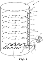
- the thermal energy system 1 is provided for performing the method according to the invention and thereto comprises a thermal energy buffer 10 and a controller 3 provided to perform the method according to the invention.
- Figure 1 shows that the thermal energy buffer 10 and the controller 3 are incorporated in a single device, in this case a domestic system, more specifically a domestic hot water system, even more specific a water heating unit 18 of a domestic hot water system.
- a domestic system more specifically a domestic hot water system
- a water heating unit 18 of a domestic hot water system for example allows to replace an older water heating unit by a new water heating unit 18 with a controller without having to adapt the contacts with, for example, the power grid, etc.
- the controller 3 and the thermal energy buffer 10 can also be physically different devices, for example when several thermal energy buffers 10 are connected to a single controller 3, allowing reduction of the number of controllers 3 necessary.
- the thermal energy buffer 10 contains thermal buffering medium 2 which preferably is a liquid thermal buffering medium.
- the thermal buffering medium 2 can be any medium known to the person skilled in the art which allows to store thermal energy in it, but preferably is water as water is known to have good thermal storage properties, is safe and is widely available.
- the thermal energy buffer can also be used to provide a household with warm water making it a water heating unit 18 of a domestic hot water system. This is however not critical for the invention and the thermal energy buffer 10 can also be used in combination with a heat pump such that heat recovered by the heat pump can be temporarily stored in the thermal energy buffer 10.
- buffering media are however also possible, such as for example gels having good thermal storage properties.
- the controller 3 is provided to control a heater 4 of the thermal buffer 10.
- the heater 4 shown in figure 1 is an electric heater and is situated at the bottom of a tank inside the thermal energy buffer 10. Such a configuration is however not critical for the invention. It is for example possible to provide a heater 4 which is not electric but which, for example, uses gas, petrol, diesel fuel, etc. Also, the position of the heater 4 is not critical for the invention and can be at the bottom, near the middle, near the top, etc. However, by providing the heater 4 near the bottom it has been found that natural heat convection of the thermal buffering medium 2 when heated by the heater 4 allows that the thermal buffering medium 2 is heated homogeneously, as depicted for example in figure 2a which will be explained in more detail below.
- the thermal energy buffer 10 shown in figure 1 comprises an inlet 5 and an outlet 6.
- the inlet 5 is positioned such that the thermal buffering medium 2 enters the thermal energy buffer at the bottom and the outlet 6 is positioned such that the thermal buffering medium 2 exits the thermal energy buffer 10 at the top.
- heated thermal buffering medium 2 which rises to the top due to convection, becomes near to the outlet 6.
- the heater 4 preferably is located near the bottom, cold thermal buffering medium 2 entering near the bottom through the inlet 5, is heated by the heater 4 and afterwards rises to the top where the outlet 6 is located.
- Such a configuration has been found to further improve the homogeneous heating of the thermal buffering medium 2.
- inlet 5 and the outlet 6 are not critical for the invention. Although they are shown here as pipes entering and leaving the thermal energy buffer 10 at the bottom and the top respectively, this is not critical for the invention.
- the inlet pipe 5 could for example enter the thermal energy buffer at the top of the thermal energy buffer going down through the thermal energy buffer 10 such that the thermal buffering medium 2 exits the inlet 5 near the bottom of the thermal energy buffer 10.
- the inlet 5 and the outlet 6 are configured such that the thermal energy buffer 10, preferably the tank provided in it, is substantially always, preferably always, filled with thermal buffering medium.
- this is obtained by configuring the inlet 5 and the outlet 6 such that when thermal buffering medium 2 is drawn from the thermal energy buffer 10 through the outlet 6, new thermal buffering medium 2 is led into the thermal energy buffer through the inlet 5 until the thermal energy buffer 2 is, preferably its tank, is filled again with thermal buffering medium 2 such that the tank remains substantially filled, preferably filled.
- the volume of the thermal buffering medium 2, and accordingly the tank of the thermal energy buffer in which it is contained, is subdivided in at least one part 21 and suitably in a number of parts 21, 22, 23, 24, 25, 26, 27.
- at least two parts are provided, more preferably even more such as for example at least three, four, five, six, seven eight, etc.
- the number of parts is not limited and can be determined by the person skilled in the art.
- the parts 21, 22, 23, 24, 25, 26, 27 subdividing the volume of the thermal energy medium are provided on top of each other along an upright direction forming a stack of parts 21, 22, 23, 24, 25, 26, 27.
- the different parts 21, 22, 23, 24, 25, 26, 27 of the volume of the thermal buffering medium 2 together form the total thermal buffering medium 2 present in the thermal energy buffer 10 and the thermal energy buffer 10 comprises a number of respective one or more temperature sensors 11, 12, 13, 14, 15, 16, 17 for each part 21, 22, 23, 24, 25, 26, 27 for sensing a temperature of the thermal buffering medium 2 contained in the corresponding part 21, 22, 23, 24, 25, 26, 27.
- the number of temperature sensors is not limited and can be determined by the person skilled in the art.
- the sensors 11, 12, 13, 14, 15, 16, 17 are placed along the thermal energy buffer 10 such that the position of each of these sensors corresponds to the position of each of the corresponding parts 21, 22, 23, 24, 25, 26, 27 subdividing the total volume of the thermal buffering medium 2.
- the temperature sensors are equidistantially distributed along the height of the thermal energy buffer 10, or along the height of the tank 18 comprised by the thermal energy buffer 10 and containing the thermal buffering medium 2.
- the controller 3 is provided with at least one signal representing at least one thermal value related to the thermal energy buffer, wherein the at least one thermal energy value comprises a predetermined minimum amount of energy present in the thermal energy buffer and an amount of thermal energy present in the thermal energy buffer.
- the controller 3 for buffering thermal energy of a thermal energy buffer is adapted to perform a method according to the present invention or implement a system in accordance with the present invention.
- the controller can be implemented as a microcontroller and may include a processor such as a microprocessor or an FPGA and one or more memories.
- the processor can be adapted to execute any of the software of the present invention.
- the predetermined minimum amount of energy preferably can be set by a user through an interface which is connected to the controller.
- the interface can for example be provided on the thermal energy buffer 10 in the form of a screen, possibly with buttons added to the screen, reflecting information of the thermal energy buffer 10.
- This is however not critical for the invention and the interface can also be a computer 8 which is connected to the controller 3, over for example a computer network 7.
- the computer network 7 can for example be a LAN or the internet and can be a physical wire or, for example, wireless network such as for example WIFI.
- the controller 3, for example, is provided with a server application, for example a web server application, allowing the computer 8 to log in to the website to set, for example, the predetermined values of the thermal energy values.
- the controller 3 is provided to calculate a value representing the amount of total thermal energy present in the thermal energy buffer by multiplying the temperature measured by each sensor 11, 12, 13, 14, 15, 16, or 17 corresponding to respectively part 21, 22, 23, 24, 25, 26, 27 of the thermal buffering medium 2 with the volume of the corresponding part of thermal buffering medium 2 such as to obtain a value representing the partial thermal energy contained in the corresponding part of the thermal buffering medium 2 and adding the resulting partial thermal energy values to each other.
- the controller 3 shown in figure 1 directly interconnects the heater 4 to the power grid through power lines 19, 20. This is however not critical for the invention and the controller 3 could also control a separate switch connecting/disconnecting the heater 4 to the power grid. Naturally, in stead of a power grid, depending o the type of heater 4, a different source of heat can be used such as for example diesel fuel, gas, etc.
- the controller 3 further calculates the amount of thermal energy present in the thermal energy buffer 10 by only using the parts 21, 22, 23, 24, 25, 26, 27 containing thermal buffering medium 2 having a temperature measured by their respective sensor which is higher than or equal to a predetermined minimum temperature, which may be part of the thermal energy values.
- a predetermined minimum temperature which may be part of the thermal energy values.
- the temperature sensors at the bottom will record a temperature which may be lower than the predetermined minimum temperature such that these parts are not taken into account when calculating the thermal energy present in the thermal energy buffer 10.
- the controller 3 uses the temperature measured by the temperature sensors 11, 12, 13, 14, 15, 16, 17 with respect to the predetermined minimum temperature. This is preferably done by a subtraction of the measured temperature with the predetermined minimum temperature.
- the thermal energy values also comprise a predetermined maximum temperature, which preferably can be set by a user according to his preferences, such as for example the desired level of comfort.
- the predetermined maximum temperature is determined such that the thermal buffering medium, which preferably liquid or semi-liquid, does not start boiling as in such case the pressure inside the preferred tank of the thermal energy buffer would start to rise such that the risk that explosions occur would increase.
- the controller 3 further calculates the amount of thermal energy present in the thermal energy buffer 10 by dividing the value representing the amount of thermal energy present in the thermal energy buffer with the value representing the maximum amount of thermal energy stored in the thermal energy buffer.
- the value is the State of Charge (SoC).
- SoC State of Charge
- the controller calculates SoC, i.e.
- the controller calculates SOC, i.e. the amount of thermal energy present in the thermal energy buffer by dividing the value representing the amount of thermal energy present in the thermal energy buffer with the total volume of the thermal buffering medium 2 multiplied with the difference between the predetermined minimum and maximum temperature.
- the thermal energy values comprise a minimal amount of heating energy representing the amount of energy required to heat all the thermal buffering medium 2 to a predetermined minimum temperature, using the heater 4, starting from the amount of thermal energy present in the thermal energy buffer 10.
- the controller 3 calculates the minimal amount of heating energy by multiplying the difference of the predetermined minimum temperature and the temperature measured by the temperature sensors sensing the temperature of the parts 21, 22, 23, 24, 25, 26, 27 containing thermal buffering medium having a temperature measured by their respective sensors 11, 12, 13, 14, 15, 16, 17 which is lower than the predetermined minimum temperature within the respective volumes of the parts 21, 22, 23, 24, 25, 26, 27 containing thermal buffering medium 2 having a temperature measured by their respective sensors 11, 12, 13, 14, 15, 16, 17 which is lower than the predetermined minimum temperature and adding the resulting values to each other.
- the thermal energy values comprise a maximal amount of heating energy representing the amount of energy required to, using the heater, heat all the thermal buffering medium to a maximum temperature starting from the amount of thermal energy present in the thermal energy buffer.
- the controller 3 calculates the maximal amount of heating energy by at least multiplying the difference of the predetermined maximum temperature and the temperature measured by the at least one temperature sensor 11, 12, 13, 14, 15, 16, 17 with the respective volume of the part 21, 22, 23, 24, 25, 26, 27 corresponding to the temperature sensor 11, 12, 13, 14, 15, 16, 17 and adding the resulting values to each other.
- SoC ⁇ i i : 0 ⁇ n , ⁇ j j : 0 ⁇ n , T j ⁇ T min ⁇ ⁇ 100 ⁇ j V j T j ⁇ T min ⁇ ⁇ i V i T max ⁇ T min ⁇ wherein:
- the state of charge is calculated as a percentage, this is not critical for the invention and the state of charge can also be calculated as a value between 0 and 1 by leaving out the multiplication by 100.
- the SoC min can be calculated and used as a control variable. SoC min is the minimum SoC that must be maintained by any demand response control system to ensure that hot water is available to meet users' immediate demands.
- E max E min + 4.186 3600 T max ⁇ T min ⁇ 1 ⁇ SoC 100 V t
- E min E max ⁇ 4.186 3600 T max ⁇ T min ⁇ 1 ⁇ SoC 100 V t
- the predetermined energy values which can be set by a user according to his preferences, such as for example corresponding to a "comfort" status, for example are 35°C - 50°C, preferably 40°C, for T min , 60°C -90°C, preferably 70°C, for T max , 5% - 50%, preferably 20%, for the predetermined minimum amount of energy present in the thermal energy buffer.
- the controller 3 is provided to control a heater 4 of the thermal buffer 10 in function of the thermal energy values such that the amount of thermal energy present in the thermal energy buffer 10 is higher than or equals the predetermined minimum amount of energy present in the thermal energy buffer 10.
- wires 19 interconnecting the different temperature sensors 11, 12, 13, 14, 15, 16, 17 to the controller are guided to the outside of the thermal energy buffer 10 at substantially the respective locations of the temperature sensors 11, 12, 13, 14, 15, 16, 17 and are subsequently connected to the controller 3, which is schematically shown in figure 1 .
- the heater 4 is positioned below the lowest temperature sensor 17 as shown in figure 1 .
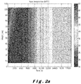
- Figure 2a shows a simulation of the temperature sensed by the different sensors along height direction of the thermal energy buffer 10, in this case a water heating unit 18, in function of time after initially using all heater water contained in the thermal energy buffer 10 and subsequently heating the newly added water.
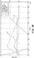
- Figure 2b shows different thermal energy values such as the state of charge 28 (%, with the scale shown at the right-hand side), the E max 29 (kWh) and the E min 30 (kWh).
- Figure 3a shows a simulation of the temperature sensed by the different sensors along height direction of the thermal energy buffer 10, in this case a water heating unit 18, in function of time after initially using all heater water contained in the thermal energy buffer 10 and subsequently heating the newly added water.
- the heater 4 is not situated below the lowest temperature sensor and it can be observed that a distorted temperature profile is being measured making it distorting a the representation of the different thermal energy values shown in figure 3b such as the state of charge 28, the E max 29, the E min 30 and the measured energy.
- the present invention comprises a controller for carrying out any of the methods of the present invention.
- the controller may have a processing engine such as a microprocessor or an FPGA which is able to execute a program.
- This program may include software having code segments which when executed on the processing engine, are adapted to receive at least one signal representing at least one thermal energy value related to the thermal energy buffer, and to calculate an at least one thermal energy value comprising a predetermined minimum amount of thermal energy present in the thermal energy buffer and an amount of thermal energy present in the thermal energy buffer.
- the software may be adapted to provide signals to control a heater of the thermal buffer in function of the thermal energy values such that the amount of thermal energy present in the thermal energy buffer is higher than or equals the predetermined minimum amount of energy present in the thermal energy buffer.
- the software may also be adapted to calculate a value representing the amount of thermal energy present in the thermal energy buffer, whereby the thermal energy values comprise a minimal amount of heating energy representing the amount of energy required to, using the heater, heat all the thermal buffering medium to a predetermined minimum temperature starting from the amount of thermal energy present in the thermal energy buffer, and the thermal energy values also comprise a maximal amount of heating energy representing the amount of energy required to heat all the thermal buffering medium to a predetermined maximum temperature, using the heater, starting from the amount of thermal energy present in the thermal energy buffer.
- the software may be adapted to calculate a thermal energy value that comprises the amount of thermal energy present in the thermal energy buffer by dividing the value representing the amount of thermal energy present in the thermal energy buffer with the value representing the maximum amount of thermal energy stored in the thermal energy buffer.
- the value is the State of Charge (SoC).
- SoC State of Charge
- the controller calculates SOC, i.e. the amount of thermal energy present in the thermal energy buffer by dividing the value representing the amount of thermal energy present in the thermal energy buffer with the total volume of the thermal buffering medium multiplied with the difference between a predetermined minimum and maximum temperature.
- the volume of the thermal buffering medium can be subdivided in one or more different parts such that the different parts of the volume of the thermal buffering medium together form the total thermal buffering medium present in the thermal energy buffer; and the thermal energy buffer can comprise a respective temperature sensor for each part for sensing a temperature of the thermal buffering medium contained in the part.
- the software can be adapted to calculate a value representing the amount of thermal energy present in the thermal energy buffer by multiplying the temperature measured by the one or more sensors sensing the temperature of the one or more different parts of the thermal buffering medium with the volume of the part of thermal buffering medium such as to obtain at least one value representing the partial thermal energy contained in the at least one part by the thermal buffering medium and adding the resulting at least one partial thermal energy value to each other.
- the software may be adapted to calculate the minimal amount of heating energy by multiplying the difference of the predetermined minimum temperature and the temperature measured by the one or more temperature sensors of the one or more parts containing thermal buffering medium having a temperature measured by their respective sensors which is lower than the predetermined minimum temperature with the respective volumes of the parts containing thermal buffering medium having a temperature measured by their respective sensors which is lower than the predetermined minimum temperature and adding the resulting values to each other.
- the software can be adapted to calculate the maximal amount of heating energy by at least multiplying the difference of the predetermined maximum temperature and the temperature measured by the one or more temperature sensors with the respective volume of the part corresponding to the temperature sensor (and adding the resulting values to each other.
- the software can be adapted to calculate the amount of thermal energy present in the thermal energy buffer by only using the parts containing thermal buffering medium having a temperature measured by their respective sensor which is higher than or equal to the predetermined minimum temperature.
- the software may be compiled for a target processing engine in the controller.
- the software may be written in an interpretative language such as Java and the controller may include a processor with an interpreter configured as a virtual machine.
- the software may be supplied in executable form on a non-transient signal storage medium such as an optical disk (e.g. DVD- or CD-ROM), magnetic tape, magnetic disk (diskette, hard drive), solid state memory (RAM, USB memory stick, solid state drive).
- a non-transient signal storage medium such as an optical disk (e.g. DVD- or CD-ROM), magnetic tape, magnetic disk (diskette, hard drive), solid state memory (RAM, USB memory stick, solid state drive).
Landscapes
- Engineering & Computer Science (AREA)
- Physics & Mathematics (AREA)
- General Engineering & Computer Science (AREA)
- Chemical & Material Sciences (AREA)
- Combustion & Propulsion (AREA)
- Thermal Sciences (AREA)
- Mechanical Engineering (AREA)
- General Physics & Mathematics (AREA)
- Automation & Control Theory (AREA)
- Remote Sensing (AREA)
- Computer Hardware Design (AREA)
- Heat-Pump Type And Storage Water Heaters (AREA)
- Control Of Temperature (AREA)
- Central Heating Systems (AREA)
Description
- The current invention relates to a method for buffering thermal energy according to the preamble of the first claim.
- The present invention also relates to a thermal energy buffer system for buffering thermal energy.
- The present invention also relates to software for executing the method or for implementing the above system.
- Methods for buffering thermal energy and thermal energy buffers are already known to the person skilled in the art. An example of a thermal energy buffer is for example a water heating unit of a domestic hot water system. Such a thermal energy buffer contains a thermal buffering medium, often water, contained in a tank and a controller controlling a heater of the thermal buffer. The heater can for example be an electrical heater provided at the bottom of the tank. In such water heating units, water often enters the tank at the bottom of the tank and exits the tank at the top. The controller is provided to receive a signal representing three signals representing thermal energy values related to the thermal energy buffer. These values purely represent temperatures and often are a minimum temperature, a maximum temperature and the temperature of the water in the tank measured by, for example, a sensor present in the tank at a certain location. When the temperature measured by the sensor drops below the minimum temperature, the controller activates the heater, for example until the maximum temperature is obtained. In such a configuration the minimum temperature represents the predetermined minimum amount of energy present in the thermal energy buffer.
- However, such methods and corresponding water heating units can not be readily implemented in a so called smart-grid in which agents determine the functioning of the heater in function of energy price, amount of energy needed, flexibility of the energy consumption of the water heating unit, availability of renewable energy, etc.
- Moreover, it has been found that when multiple water heating units of domestic hot water systems are for example controlled by a single controller using the thermal energy values provided by the different thermal energy buffers to the controller, the thermal energy values being expressed in, for example, degrees Celsius, controlling the water heating units in a consistent way such that the amount of energy of the different water heating units can be compared is not easy as the different thermal energy values are determined for different water heating units having different volumes for the tank, have different positions of the sensor sensing the temperature of the water in the waterheating unit, etc.
- Although domestic water boilers of a complete population consume a great deal of energy and hence could contribute to maintaining stable network values if properly controlled, little progress has been made in coordinating the switching of these boilers other than to switch them on at night to make use of a night tariff. Any network connections at domestic premises are a potential security threat as they become easily accessible. It is not obvious how to improve this situation.
-
JP9068369 JP2004218873 WO88/05160 EP2146309 andUS2005/019631 are examples of known methods and systems for buffering thermal energy in a thermal buffering medium. - Therefore, it is an object of the current invention to provide an alternative method for buffering thermal energy and an alternative thermal energy buffer system. To achieve certain improvements embodiments of the present invention can provide one or more advantages:
- at least one thermal energy buffer can be controlled more easily by a controller regardless of specific details of the thermal energy buffer,
- local controllers can be used which do not require access to wide area networks and their security threats while still providing more flexibility of local control of heating energy,
- in case of hierarchical market based control systems the demand bid curve can be controlled effectively by provision of a suitable control variable,
- in case of a time of use (ToU) demand response system such as based on variable day-ahead prices for multiple fixed time blocks per day, the scheduling of the energy buffer can be based on the cheapest allocation of a first parameter with a planning horizon proportional to a second parameter, and/or
- with Variable Connection Capacity in which real time limits are set on a household level for both consumption and production, the scheduling of the energy buffer can also be based on the cheapest allocation of a first parameter with a planning horizon proportional to a second parameter.
- Such benefits can be achieved according to the method for buffering thermal energy according to any of claims 1-6.
- According to the invention, the controller calculates values representing amounts of thermal energy, comprising a minimal amount of heating energy representing the amount of energy (Emin) required to, using the heater, heat all the thermal buffering medium to a predetermined minimum temperature starting from the amount of thermal energy present in the thermal energy buffer. The predetermined minimum temperature is preferably the preferred minimum temperature at which water leaves the thermal energy buffer. According to the invention, the thermal energy values comprise also a maximal amount of heating energy (Emax) representing the amount of energy required to, using the heater, heat all the thermal buffering medium to a predetermined maximum temperature starting from the amount of thermal energy present in the thermal energy buffer.
- It has been found that such a minimal and/or maximal amount of heating energy allows the method or system to be employed together with other devices in a smart grid control system with an increased ease.
- According to preferred embodiments of the current invention, the controller calculates the amount of thermal energy present in the thermal energy buffer by dividing the value representing the amount of thermal energy present in the thermal energy buffer with the value representing the maximum amount of thermal energy stored in the thermal energy buffer. The value is the State of Charge (SoC). In a specific embodiment, the controller calculates SOC, i.e. the amount of thermal energy present in the thermal energy buffer by dividing the value representing the amount of thermal energy present in the thermal energy buffer with the total volume of the thermal buffering medium multiplied with the difference between the predetermined minimum and maximum temperature.
- According to the invention, another value calculated by the controller is the total amount, of thermal energy present in the thermal energy buffer, said value being the sum of values each representing the thermal energy measured for a different part of the thermal buffering medium and each calculated by multiplying the temperature measured by the sensor of at least one part of the thermal buffering medium with the volume of the part of thermal buffering medium such as to obtain at least one value representing the partial thermal energy contained in the at least one part by the thermal buffering medium.
- Such a calculated thermal energy value, next to taking into account the temperature of the volume of thermal buffering medium, such as for example water, also takes into account the volume itself of the thermal buffering medium such that a better representation of the energy content of the thermal buffering medium is obtained. Such an energy content can then be used to represent the thermal energy values and it has been found that, for example, thermal energy values represented in this way can be successfully used to control completely different thermal energy buffers with a single controller.
- Moreover, it has been found that such a thermal energy buffer can be used in a smart grid control system such as for example the method described in the European patent application
EP11162735.2 - at least one thermal energy buffer can be controlled more easily by a controller regardless of specific details of the thermal energy buffer by using an interface that provides certain energy values that can be used for control purposes. These values can include any of , any combination of, or
- all of Emax, Emin, State of charge (SoC) and optionally for example SoCmin which is the minimum SoC that must be maintained by any demand response control system to ensure that hot water is available to meet users' immediate demands and/or P, the electrical power consumption of the buffer;
- local controllers can be used which do not require access to wide area networks and their security threats while still providing more flexibility of local control of heating energy,
- in case of hierarchical market based control systems the demand bid curve can be controlled effectively by provision of a suitable control variable such as a slope or priority inversely proportional to SoC - SoCmin, weighted proportional to Emin;
- in case of a time of use (ToU) demand response system such as based on variable day-ahead prices for multiple fixed time blocks per day, the scheduling of the energy buffer can be based on the cheapest allocation of a first parameter such as tmax with a planning horizon proportional to a second parameter such as SoC - SoCmin, and/or
- with Variable Connection Capacity (VCC) in which real time limits are set on a household level for both consumption and production, the scheduling of the energy buffer can also be based on the cheapest allocation of a first parameter tmax with a planning horizon proportional to a second parameter such as SoC- SoCmin. tmax is the time required to fully charge the buffer.
- According to preferred embodiments of the current invention, the thermal energy buffer is a water heating unit of a domestic hot water system.
- According to preferred embodiments of the current invention, the thermal buffering medium is water.
- According to the current invention, the controller calculates the minimal amount of heating energy by multiplying the difference of the predetermined minimum temperature and the temperature measured by the one or more temperature sensors of the one or more parts containing thermal buffering medium having a temperature measured by their respective sensors which is lower than the predetermined minimum temperature with the respective volumes of the parts containing thermal buffering medium having a temperature measured by their respective sensors which is lower than the predetermined minimum temperature and adding the resulting values to each other.
- According to the current invention, the controller calculates the maximum amount of heating energy by at least multiplying the difference of the predetermined maximum temperature and the temperature measured by the one or more temperature sensors with the respective volume of the part corresponding to the temperature sensor and adding the resulting values to each other.
- Such a calculated minimal and/or maximal thermal energy value, next to taking into account the temperature of the volume of thermal buffering medium, such as for example water, also takes into account the volume itself of the thermal buffering medium considered. Such an energy content can be easily used to represent the thermal energy values and it has been found that, for example, thermal energy values represented in this way can be successfully used to control completely different thermal energy buffers with a single controller. For example, it has been found that such a thermal energy buffer can be used in the method described in the European patent application
EP11162735.2 - According to the current invention the controller uses the temperature measured by the one or more temperature sensors with respect to the predetermined minimum temperature. This allows to calculate the amount of thermal energy present in the thermal energy buffer relative to the maximum total amount of energy which can be present in the thermal energy buffer, defined by the multiplication of the predetermined maximum temperature and the total volume of the thermal buffering medium, and with respect to the predetermined minimum temperature.
- According to preferred embodiments of the current invention, the controller further calculates the amount of thermal energy present in the thermal energy buffer by only using the parts containing thermal buffering medium having a temperature measured by their respective sensor which is higher than or equal to the predetermined minimum temperature. According to such embodiments, the amount of thermal energy present in the thermal energy buffer calculated by the controller for example range from 0 to 1, such that an indication of the state of charge of the thermal energy buffer can be provided by the controller which can be interpreted independently from other parameters and which therefore can be incorporated in smart grid network with increased ease. If required the indication of the state of charge can be represented as a percentage by multiplying it by 100.
- According to preferred embodiments of the current invention, the one or more parts subdividing the volume of the thermal energy medium are provided on top of each other along an upright direction forming a stack of parts. Such a subdivision of the volume of the thermal buffering medium has been found to result in good representations of the amount of thermal energy present in the thermal energy buffer. Indeed, in such thermal buffers, such as for example water heating units of domestic hot water systems, a vertical distribution of temperatures of the thermal buffering medium is present, which can be relatively good approximated by such a stack of parts.
- According to preferred embodiments of the current invention, the heater is positioned below the lowest temperature sensor. It has been found that such a positioning allows a better representation of the thermal energy present in the thermal energy buffer.
- According to preferred embodiments of the current invention, wires interconnecting the different temperature sensors to the controller are guided to the outside of the thermal energy buffer at substantially the respective locations of the temperature sensors. Such an interconnection of the different wires interconnecting the temperature sensors to the controller prevents that temperature sensors near wires leaving the thermal energy buffer at the same location are unwontedly affected by a leakage of heat along these wires giving rise to an unwanted disturbance of the temperature measurement by the temperature sensor, as is for example the case when the different wires coming from the different temperature sensors are assembled within the thermal energy buffer and leave the thermal energy buffer at substantially that same location, the different wires, often being made of material having good thermal conducting properties, in such a case forming a heat or cold bridge to the outside having an increased risk for heat leaving the thermal energy buffer along it.
- The invention also relates to a thermal energy buffer system provided for performing the method according to the invention, comprising a thermal energy buffer and a controller according to any of the claims 7-14. The present invention also provides a computer program product according to claim 15 having code segments which when executed on a processing engine execute any of the methods according to the present invention. The present invention also provides a non-transient signal storage medium according to claim 15 for storing the computer program product. The storage medium can be for example an optical disk such as a CD-Rom or DVD-ROM, a magnetic tape, a magnetic disk, a solid state memory etc.
- The controller can be implemented as a microcontroller and may include a processor such as a microprocessor or an FPGA and one or more memories.
- In the following detailed description, numerous specific details are set forth in order to provide a thorough understanding of the invention and how it may be practiced in particular embodiments. However, it will be understood that the present invention may be practiced without these specific details. In other instances, well-known methods, procedures and techniques have not been described in detail, so as not to obscure the present invention.
- The present invention will be described with respect to particular embodiments and with reference to certain drawings but the invention is not limited thereto but only by the claims. The drawings described are only schematic and are non-limiting. In the drawings, the size of some of the elements may be exaggerated and not drawn on scale for illustrative purposes. The dimensions and the relative dimensions do not necessarily correspond to actual reductions to practice of the invention.
- Furthermore, the terms first, second, third and the like in the description and in the claims, are used for distinguishing between similar elements and not necessarily for describing a sequential or chronological order. The terms are interchangeable under appropriate circumstances and the embodiments of the invention can operate in other sequences than described or illustrated herein.
- Moreover, the terms top, bottom, over, under and the like in the description and the claims are used for descriptive purposes and not necessarily for describing relative positions. It is to be understood that the terms so used are interchangeable under appropriate circumstances and that the embodiments of the invention described herein are capable of operation in other orientations than described or illustrated herein.
- The term "comprising", used in the claims, should not be interpreted as being restricted to the means listed thereafter; it does not exclude other elements or steps. It needs to be interpreted as specifying the presence of the stated features, integers, steps or components as referred to, but does not preclude the presence or addition of one or more other features, integers, steps or components, or groups thereof. Thus, the scope of the expression "a device comprising means A and B" should not be limited to devices consisting only of components A and B.
-
Figure 1 shows an overview of a thermal energy buffer system according to the invention. -
Figure 2a shows a simulation of the temperature sensed by the different sensors along height direction of thethermal energy buffer 10, in this case awater heating unit 18, in function of time after initially using all heater water contained in thethermal energy buffer 10 and subsequently heating the newly added water which initially entered the heating unit at about 15°C. -
Figure 2b shows different thermal energy values such as the state ofcharge 28, theE max 29 and theE min 30. -
Figure 3a and3b show the results of a different simulation as the one shown infigures 2a and2b . - The
thermal energy system 1 is provided for performing the method according to the invention and thereto comprises athermal energy buffer 10 and acontroller 3 provided to perform the method according to the invention. -
Figure 1 shows that thethermal energy buffer 10 and thecontroller 3 are incorporated in a single device, in this case a domestic system, more specifically a domestic hot water system, even more specific awater heating unit 18 of a domestic hot water system. Such a configuration for example allows to replace an older water heating unit by a newwater heating unit 18 with a controller without having to adapt the contacts with, for example, the power grid, etc. This is however not critical for the invention and thecontroller 3 and thethermal energy buffer 10 can also be physically different devices, for example when severalthermal energy buffers 10 are connected to asingle controller 3, allowing reduction of the number ofcontrollers 3 necessary. - The
thermal energy buffer 10 containsthermal buffering medium 2 which preferably is a liquid thermal buffering medium. Thethermal buffering medium 2 can be any medium known to the person skilled in the art which allows to store thermal energy in it, but preferably is water as water is known to have good thermal storage properties, is safe and is widely available. Moreover, but not limited thereto, in such case the thermal energy buffer can also be used to provide a household with warm water making it awater heating unit 18 of a domestic hot water system. This is however not critical for the invention and thethermal energy buffer 10 can also be used in combination with a heat pump such that heat recovered by the heat pump can be temporarily stored in thethermal energy buffer 10. - Other buffering media are however also possible, such as for example gels having good thermal storage properties.
- The
controller 3 is provided to control aheater 4 of thethermal buffer 10. Theheater 4 shown infigure 1 is an electric heater and is situated at the bottom of a tank inside thethermal energy buffer 10. Such a configuration is however not critical for the invention. It is for example possible to provide aheater 4 which is not electric but which, for example, uses gas, petrol, diesel fuel, etc. Also, the position of theheater 4 is not critical for the invention and can be at the bottom, near the middle, near the top, etc. However, by providing theheater 4 near the bottom it has been found that natural heat convection of thethermal buffering medium 2 when heated by theheater 4 allows that thethermal buffering medium 2 is heated homogeneously, as depicted for example infigure 2a which will be explained in more detail below. - The
thermal energy buffer 10 shown infigure 1 comprises aninlet 5 and anoutlet 6. Theinlet 5 is positioned such that thethermal buffering medium 2 enters the thermal energy buffer at the bottom and theoutlet 6 is positioned such that thethermal buffering medium 2 exits thethermal energy buffer 10 at the top. This has as a consequence that heatedthermal buffering medium 2, which rises to the top due to convection, becomes near to theoutlet 6. As theheater 4 preferably is located near the bottom, coldthermal buffering medium 2 entering near the bottom through theinlet 5, is heated by theheater 4 and afterwards rises to the top where theoutlet 6 is located. Such a configuration has been found to further improve the homogeneous heating of thethermal buffering medium 2. - The exact configuration of the
inlet 5 and theoutlet 6 is not critical for the invention. Although they are shown here as pipes entering and leaving thethermal energy buffer 10 at the bottom and the top respectively, this is not critical for the invention. For example theinlet pipe 5 could for example enter the thermal energy buffer at the top of the thermal energy buffer going down through thethermal energy buffer 10 such that thethermal buffering medium 2 exits theinlet 5 near the bottom of thethermal energy buffer 10. - Preferably, the
inlet 5 and theoutlet 6 are configured such that thethermal energy buffer 10, preferably the tank provided in it, is substantially always, preferably always, filled with thermal buffering medium. Preferably this is obtained by configuring theinlet 5 and theoutlet 6 such that whenthermal buffering medium 2 is drawn from thethermal energy buffer 10 through theoutlet 6, newthermal buffering medium 2 is led into the thermal energy buffer through theinlet 5 until thethermal energy buffer 2 is, preferably its tank, is filled again withthermal buffering medium 2 such that the tank remains substantially filled, preferably filled. - The volume of the
thermal buffering medium 2, and accordingly the tank of the thermal energy buffer in which it is contained, is subdivided in at least onepart 21 and suitably in a number ofparts figure 1 , theparts parts - As can be seen in
figure 1 , thedifferent parts thermal buffering medium 2 together form the totalthermal buffering medium 2 present in thethermal energy buffer 10 and thethermal energy buffer 10 comprises a number of respective one ormore temperature sensors part thermal buffering medium 2 contained in thecorresponding part parts thermal buffering medium 2 as the temperature varies substantially only in height direction. As for the parts, the number of temperature sensors is not limited and can be determined by the person skilled in the art. - Although the
parts figure 1 , it is to be understood that theparts thermal buffering medium 2 and not physically. - Preferably, the
sensors thermal energy buffer 10 such that the position of each of these sensors corresponds to the position of each of the correspondingparts thermal buffering medium 2. Thereto, preferably the temperature sensors are equidistantially distributed along the height of thethermal energy buffer 10, or along the height of thetank 18 comprised by thethermal energy buffer 10 and containing thethermal buffering medium 2. - The
controller 3 is provided with at least one signal representing at least one thermal value related to the thermal energy buffer, wherein the at least one thermal energy value comprises a predetermined minimum amount of energy present in the thermal energy buffer and an amount of thermal energy present in the thermal energy buffer. - The
controller 3 for buffering thermal energy of a thermal energy buffer is adapted to perform a method according to the present invention or implement a system in accordance with the present invention. The controller can be implemented as a microcontroller and may include a processor such as a microprocessor or an FPGA and one or more memories. The processor can be adapted to execute any of the software of the present invention. - The predetermined minimum amount of energy preferably can be set by a user through an interface which is connected to the controller. The interface can for example be provided on the
thermal energy buffer 10 in the form of a screen, possibly with buttons added to the screen, reflecting information of thethermal energy buffer 10. This is however not critical for the invention and the interface can also be acomputer 8 which is connected to thecontroller 3, over for example acomputer network 7. Thecomputer network 7 can for example be a LAN or the internet and can be a physical wire or, for example, wireless network such as for example WIFI. Thecontroller 3, for example, is provided with a server application, for example a web server application, allowing thecomputer 8 to log in to the website to set, for example, the predetermined values of the thermal energy values. - The
controller 3 is provided to calculate a value representing the amount of total thermal energy present in the thermal energy buffer by multiplying the temperature measured by eachsensor part thermal buffering medium 2 with the volume of the corresponding part ofthermal buffering medium 2 such as to obtain a value representing the partial thermal energy contained in the corresponding part of thethermal buffering medium 2 and adding the resulting partial thermal energy values to each other. - The
controller 3 shown infigure 1 directly interconnects theheater 4 to the power grid throughpower lines controller 3 could also control a separate switch connecting/disconnecting theheater 4 to the power grid. Naturally, in stead of a power grid, depending o the type ofheater 4, a different source of heat can be used such as for example diesel fuel, gas, etc. - Preferably, the
controller 3 further calculates the amount of thermal energy present in thethermal energy buffer 10 by only using theparts thermal buffering medium 2 having a temperature measured by their respective sensor which is higher than or equal to a predetermined minimum temperature, which may be part of the thermal energy values. For example, when newthermal buffering medium 2 has entered thethermal energy buffer 10 at the bottom of thethermal energy buffer 10, the temperature sensors at the bottom will record a temperature which may be lower than the predetermined minimum temperature such that these parts are not taken into account when calculating the thermal energy present in thethermal energy buffer 10. - Preferably, the
controller 3 uses the temperature measured by thetemperature sensors - Preferably, the thermal energy values also comprise a predetermined maximum temperature, which preferably can be set by a user according to his preferences, such as for example the desired level of comfort. Preferably, the predetermined maximum temperature is determined such that the thermal buffering medium, which preferably liquid or semi-liquid, does not start boiling as in such case the pressure inside the preferred tank of the thermal energy buffer would start to rise such that the risk that explosions occur would increase.
- The
controller 3 further calculates the amount of thermal energy present in thethermal energy buffer 10 by dividing the value representing the amount of thermal energy present in the thermal energy buffer with the value representing the maximum amount of thermal energy stored in the thermal energy buffer. The value is the State of Charge (SoC). In a specific embodiment, the controller calculates SoC, i.e. In a specific embodiment, the controller calculates SOC, i.e. the amount of thermal energy present in the thermal energy buffer by dividing the value representing the amount of thermal energy present in the thermal energy buffer with the total volume of thethermal buffering medium 2 multiplied with the difference between the predetermined minimum and maximum temperature. The thermal energy values comprise a minimal amount of heating energy representing the amount of energy required to heat all thethermal buffering medium 2 to a predetermined minimum temperature, using theheater 4, starting from the amount of thermal energy present in thethermal energy buffer 10. Thecontroller 3 calculates the minimal amount of heating energy by multiplying the difference of the predetermined minimum temperature and the temperature measured by the temperature sensors sensing the temperature of theparts respective sensors parts thermal buffering medium 2 having a temperature measured by theirrespective sensors 
- Tmin is a predefined minimum temperature
- n is the number of
parts - Tj is the temperature measured by the
respective temperature sensors - Vj is the volume of the
respective parts - Preferably, the thermal energy values comprise a maximal amount of heating energy representing the amount of energy required to, using the heater, heat all the thermal buffering medium to a maximum temperature starting from the amount of thermal energy present in the thermal energy buffer.
- More preferably, the
controller 3 calculates the maximal amount of heating energy by at least multiplying the difference of the predetermined maximum temperature and the temperature measured by the at least onetemperature sensor part temperature sensor 
- Tmax is a predefined maximum temperature
- n is the number of
parts - Ti is the temperature measured by the
respective temperature sensors - Vi is the volume of the
respective parts - The preferred way of calculating the amount of thermal energy present in the thermal energy buffer in such case can be mathematically represented by:

- Tmin is a predefined minimum temperature
- Tmax is a predefined maximum temperature
- n is the number of
parts - Tj is the temperature measured by the
respective temperature sensors - Vj or Vj is the volume of the
respective parts - SoC represents the state of charge, representing the amount of energy present in the thermal energy buffer as a percentage with respect to the maximum amount of energy present in the thermal energy buffer with respect to the minimal amount of heating energy.
- Although in the shown formula, the state of charge is calculated as a percentage, this is not critical for the invention and the state of charge can also be calculated as a value between 0 and 1 by leaving out the multiplication by 100. Optionally for example the SoCmin can be calculated and used as a control variable. SoCmin is the minimum SoC that must be maintained by any demand response control system to ensure that hot water is available to meet users' immediate demands.
- Although the
controller 3 can be provided to calculate the state of charge as described above the state of charge can also be calculated by thecontroller 3 by the following mathematical formula:
- Of course, the other way around it is possible to calculate the state of charge using the earlier method and to calculate Emax and Emin using either one of the following mathematical formula:


- Using these thermal energy values, the predetermined energy values, which can be set by a user according to his preferences, such as for example corresponding to a "comfort" status, for example are 35°C - 50°C, preferably 40°C, for Tmin, 60°C -90°C, preferably 70°C, for Tmax, 5% - 50%, preferably 20%, for the predetermined minimum amount of energy present in the thermal energy buffer.
- The
controller 3 is provided to control aheater 4 of thethermal buffer 10 in function of the thermal energy values such that the amount of thermal energy present in thethermal energy buffer 10 is higher than or equals the predetermined minimum amount of energy present in thethermal energy buffer 10. - Preferably,
wires 19 interconnecting thedifferent temperature sensors thermal energy buffer 10 at substantially the respective locations of thetemperature sensors controller 3, which is schematically shown infigure 1 . - Preferably, the
heater 4 is positioned below thelowest temperature sensor 17 as shown infigure 1 . -
Figure 2a shows a simulation of the temperature sensed by the different sensors along height direction of thethermal energy buffer 10, in this case awater heating unit 18, in function of time after initially using all heater water contained in thethermal energy buffer 10 and subsequently heating the newly added water. -
Figure 2b shows different thermal energy values such as the state of charge 28 (%, with the scale shown at the right-hand side), the Emax 29 (kWh) and the Emin 30 (kWh). -
Figure 3a shows a simulation of the temperature sensed by the different sensors along height direction of thethermal energy buffer 10, in this case awater heating unit 18, in function of time after initially using all heater water contained in thethermal energy buffer 10 and subsequently heating the newly added water. However in this simulation theheater 4 is not situated below the lowest temperature sensor and it can be observed that a distorted temperature profile is being measured making it distorting a the representation of the different thermal energy values shown infigure 3b such as the state ofcharge 28, theE max 29, theE min 30 and the measured energy. - The present invention comprises a controller for carrying out any of the methods of the present invention. In particular the controller may have a processing engine such as a microprocessor or an FPGA which is able to execute a program. This program may include software having code segments which when executed on the processing engine, are adapted to receive at least one signal representing at least one thermal energy value related to the thermal energy buffer, and to calculate an at least one thermal energy value comprising a predetermined minimum amount of thermal energy present in the thermal energy buffer and an amount of thermal energy present in the thermal energy buffer.
- The software may be adapted to provide signals to control a heater of the thermal buffer in function of the thermal energy values such that the amount of thermal energy present in the thermal energy buffer is higher than or equals the predetermined minimum amount of energy present in the thermal energy buffer.
- The software may also be adapted to calculate a value representing the amount of thermal energy present in the thermal energy buffer, whereby the thermal energy values comprise a minimal amount of heating energy representing the amount of energy required to, using the heater, heat all the thermal buffering medium to a predetermined minimum temperature starting from the amount of thermal energy present in the thermal energy buffer, and the thermal energy values also comprise a maximal amount of heating energy representing the amount of energy required to heat all the thermal buffering medium to a predetermined maximum temperature, using the heater, starting from the amount of thermal energy present in the thermal energy buffer.
- The software may be adapted to calculate a thermal energy value that comprises the amount of thermal energy present in the thermal energy buffer by dividing the value representing the amount of thermal energy present in the thermal energy buffer with the value representing the maximum amount of thermal energy stored in the thermal energy buffer. The value is the State of Charge (SoC). In a specific embodiment, the controller calculates SOC, i.e. the amount of thermal energy present in the thermal energy buffer by dividing the value representing the amount of thermal energy present in the thermal energy buffer with the total volume of the thermal buffering medium multiplied with the difference between a predetermined minimum and maximum temperature.
- For use with the software the volume of the thermal buffering medium can be subdivided in one or more different parts such that the different parts of the volume of the thermal buffering medium together form the total thermal buffering medium present in the thermal energy buffer; and the thermal energy buffer can comprise a respective temperature sensor for each part for sensing a temperature of the thermal buffering medium contained in the part. The software can be adapted to calculate a value representing the amount of thermal energy present in the thermal energy buffer by multiplying the temperature measured by the one or more sensors sensing the temperature of the one or more different parts of the thermal buffering medium with the volume of the part of thermal buffering medium such as to obtain at least one value representing the partial thermal energy contained in the at least one part by the thermal buffering medium and adding the resulting at least one partial thermal energy value to each other.
- The software may be adapted to calculate the minimal amount of heating energy by multiplying the difference of the predetermined minimum temperature and the temperature measured by the one or more temperature sensors of the one or more parts containing thermal buffering medium having a temperature measured by their respective sensors which is lower than the predetermined minimum temperature with the respective volumes of the parts containing thermal buffering medium having a temperature measured by their respective sensors which is lower than the predetermined minimum temperature and adding the resulting values to each other.
- The software can be adapted to calculate the maximal amount of heating energy by at least multiplying the difference of the predetermined maximum temperature and the temperature measured by the one or more temperature sensors with the respective volume of the part corresponding to the temperature sensor (and adding the resulting values to each other.
- The software can be adapted to calculate the amount of thermal energy present in the thermal energy buffer by only using the parts containing thermal buffering medium having a temperature measured by their respective sensor which is higher than or equal to the predetermined minimum temperature.
- The software may be compiled for a target processing engine in the controller. Alternatively the software may be written in an interpretative language such as Java and the controller may include a processor with an interpreter configured as a virtual machine.
- The software may be supplied in executable form on a non-transient signal storage medium such as an optical disk (e.g. DVD- or CD-ROM), magnetic tape, magnetic disk (diskette, hard drive), solid state memory (RAM, USB memory stick, solid state drive).
Claims (15)
- Method for buffering thermal energy in a thermal buffering medium (2) contained within a thermal energy buffer (10) having a controller (3) and a heater (4),
wherein at least one signal representing predetermined values related to the thermal energy buffer is provided to the controller (3), the predetermined values comprising :- a predetermined maximum temperature (Tmax) settable by a user,- a predetermined minimum temperature (Tmin), and- a predetermined minimum amount of thermal energy present in the thermal energy buffer settable by a user,wherein the controller (3) calculates the following thermal values:- a value representing the amount of thermal energy present in the thermal energy buffer,- a minimal amount of heating energy representing an amount of energy required to, using the heater (4), heat all the thermal buffering medium (2) to said predetermined minimum temperature starting from the amount of thermal energy present in the thermal energy buffer (10), and- a maximal amount of heating energy representing an amount of energy required to heat all the thermal buffering medium (2) to said predetermined maximum temperature, using the heater (4), starting from the amount of thermal energy present in the thermal energy buffer (10),wherein the controller (3) controls the heater (4) of the thermal buffer (10) in function of said thermal energy values such that the amount of energy present in the thermal energy buffer (10) is higher than or equals the predetermined minimum energy present in the thermal energy buffer (10),
wherein the volume of the thermal buffering medium (2) is subdivided in one or more different parts (21) such that the different parts (21) of the volume of the thermal buffering medium (2) together form the total thermal buffering medium (2) present in the thermal energy buffer (10); and the thermal energy buffer (10) comprises a respective temperature sensor (11) for each different part (21) for sensing a temperature of the thermal buffering medium (2) contained in the part (21), characterised in that
the controller (3) calculates a value representing the amount of thermal energy present in the thermal energy buffer by multiplying the temperature measured by the one or more sensors (11) sensing the temperature of the one or more different parts (21) of the thermal buffering medium (2) with the volume of the at least one part of thermal buffering medium (2) such as to obtain at least one value representing the partial thermal energy contained in the at least one part by the thermal buffering medium (2) and adding the resulting at least one partial thermal energy value to each other, wherein the controller (3) calculates the minimal amount of heating energy by multiplying the difference between the predetermined minimum temperature and the temperature measured by the one or more temperature sensors (11) of the one or more different parts (21) containing thermal buffering medium having a temperature measured by their respective sensors (11), which is lower than the predetermined minimum temperature, with the respective volume of the different parts (21) containing thermal buffering medium (2) having a temperature measured by the respective sensors (11) which is lower than the predetermined minimum temperature (Tmin), and adding the resulting values to each other, and wherein the controller (3) calculates the maximal amount of heating energy by at least multiplying the difference of the predetermined maximum temperature and the temperature measured by the one or more temperature sensors (11) with the respective volume of the part (21) corresponding to the temperature sensor (11) and adding the resulting values to each other. - Method for buffering thermal energy according to claim 1, characterized in that the thermal energy buffer (10) is a water heating unit (18) of a domestic hot water system.
- Method for buffering thermal energy according to any one of claims 1 or 2, characterized in that the controller (3) further calculates a state of charge by dividing the value representing the amount of thermal energy present in the thermal energy buffer with the value representing the maximum amount of thermal energy stored in the thermal energy buffer or the controller calculates the state of charge by dividing the value representing the amount of thermal energy present in the thermal energy buffer with the total volume of the thermal buffering medium multiplied with the difference between the predetermined minimum and maximum temperature.
- Method for buffering thermal energy according to any one of claims 1 to 3, characterized in that the controller (3) uses the temperature measured by the one or more temperature sensors (11) with respect to the predetermined minimum temperature.
- Method for buffering thermal energy according to any one of claims 1 - 4, characterized in that the controller (3) further calculates the amount of thermal energy present in the thermal energy buffer (10) by only using the different parts (21) containing thermal buffering medium (2) having a temperature measured by their respective sensor (11) which is higher than or equal to the predetermined minimum temperature.
- Method for buffering thermal energy according to any one of claims 1 - 5, characterized in that the one or more different parts (21) subdividing the volume of the thermal energy medium are provided on top of each other along an upright direction forming a stack of different parts (21).
- A thermal energy buffering system comprising
a thermal energy buffer (10) having a controller (3),
a thermal buffering medium (2) contained within said thermal energy buffer (10),
means for providing at least one signal representing predetermined values related to the thermal energy buffer (10) to the controller (3), the predetermined values comprising :- a maximum temperature (Tmax) settable by a user,- a predetermined minimum amount of thermal energy present in the thermal energy buffer (10) settable by a user, and- a predetermined minimum temperature (Tmin)wherein the controller (3) is adapted to calculate the following thermal energy values:- a value representing the amount of thermal energy present in the thermal energy buffer,- a minimal amount of heating energy representing the amount of energy required to, using the heater (4), heat all the thermal buffering medium (2) to said predetermined minimum temperature starting from the amount of thermal energy present in the thermal energy buffer (10), and- an amount of energy required to heat all the thermal buffering medium (2) to said predetermined maximum temperature, using the heater (4), starting from the amount of thermal energy present in the thermal energy buffer (10), wherein the controller (3) is adapted to control the heater (4) of the thermal buffer (10) in function of said thermal energy values such that the amount of energy present in the thermal energy buffer (10) is higher than or equals the predetermined minimum energy present in the thermal energy buffer (10), andwherein the volume of the thermal buffering medium (2) is subdivided in one or more different parts (21) such that the different parts (21) of the volume of the thermal buffering medium (2) together form the total thermal buffering medium (2) present in the thermal energy buffer (10); and the thermal energy buffer (10) comprises a respective temperature sensor (11) for each different part (21) for sensing a temperature of the thermal buffering medium (2) contained in the part (21),
characterised in that
the controller (3) is adapted to calculate a value representing the amount of thermal energy present in the thermal energy buffer by multiplying the temperature measured by the one or more sensors (11) sensing the temperature of the one or more different parts (21) of the thermal buffering medium (2) with the volume of the at least one part of thermal buffering medium (2) such as to obtain at least one value representing the partial thermal energy contained in the at least one part by the thermal buffering medium (2) and adding the resulting at least one partial thermal energy value to each other, and in that the controller (3) is adapted to calculate the minimal amount of heating energy by multiplying the difference between the predetermined minimum temperature and the temperature measured by the one or more temperature sensors of the one or more different parts (21) containing thermal buffering medium having a temperature measured by their respective sensors (11) which is lower than the predetermined minimum temperature with the respective volumes of the different parts (21) containing thermal buffering medium (2) having a temperature measured by their respective sensor (11) which is lower than the predetermined minimum temperature and adding the resulting values to each other, and in that the controller (3) is adapted to calculate the maximal amount of heating energy by at least multiplying the difference between the predetermined maximum temperature and the temperature measured by the one or more temperature sensors (11) with the respective volume of the part (21) corresponding to the temperature sensor (11) and adding the resulting values to each other. - The system according to claim 7, characterized in that the thermal energy buffer (10) is a water heating unit (18) of a domestic hot water system.
- The system according to claim 7 or 8, characterized in that the controller (3) is adapted to further calculate the state of charge by dividing the value representing the amount of thermal energy present in the thermal energy buffer with the value representing the maximum amount of thermal energy stored in the thermal energy buffer or the controller calculates the state of charge by dividing the value representing the amount of thermal energy present in the thermal energy buffer with the total volume of the thermal buffering medium multiplied with the difference between the predetermined minimum and maximum temperature.
- The system according to any one of claims 7 - 9, characterized in that the controller (3) is adapted to use the temperature measured by the one or more temperature sensors (11) with respect to the predetermined minimum temperature.
- The system according to any one of claims 7 - 10, characterized in that the controller (3) is adapted to further calculate the amount of thermal energy present in the thermal energy buffer (10) by only using the different parts (21) containing thermal buffering medium (2) having a temperature measured by their respective sensor (11) which is higher than or equal to the predetermined minimum temperature.
- The system according to any one of claims 7 - 11, characterized in that the one or more different parts (21) subdividing the volume of the thermal energy medium are provided on top of each other along an upright direction forming a stack of different parts (21).
- The system according to any one of the claims 7 - 12, characterized in that the heater (4) is positioned below the lowest temperature sensor (17).
- The system according to any one of claims 7 - 13, characterized in that wires (19) interconnecting the different temperature sensors (11) to the controller (3) are guided to the outside of the thermal energy buffer (10) at substantially the respective locations of the temperature sensors (11).
- A computer program product having code segments which when executed on a processing engine execute any of the methods according to any of the claims 1 to 6, or
a non-transient signal storage medium storing the computer program product having code segments which when executed on a processing engine execute any of the methods according to any of the claims 1 to 6.
Priority Applications (4)
| Application Number | Priority Date | Filing Date | Title |
|---|---|---|---|
| DK17160676.7T DK3214420T3 (en) | 2011-06-03 | 2012-06-04 | REGULATOR FOR BUFFERING THERMAL ENERGY |
| EP12729056.7A EP2715298B1 (en) | 2011-06-03 | 2012-06-04 | Method for buffering thermal energy and thermal energy buffer system |
| EP17160676.7A EP3214420B1 (en) | 2011-06-03 | 2012-06-04 | Controller for buffering thermal energy |
| PL17160676T PL3214420T3 (en) | 2011-06-03 | 2012-06-04 | Controller for buffering thermal energy |
Applications Claiming Priority (3)
| Application Number | Priority Date | Filing Date | Title |
|---|---|---|---|
| EP11168672 | 2011-06-03 | ||
| EP12729056.7A EP2715298B1 (en) | 2011-06-03 | 2012-06-04 | Method for buffering thermal energy and thermal energy buffer system |
| PCT/EP2012/060527 WO2012164102A2 (en) | 2011-06-03 | 2012-06-04 | Method and system for buffering thermal energy and thermal energy buffer system |
Related Child Applications (2)
| Application Number | Title | Priority Date | Filing Date |
|---|---|---|---|
| EP17160676.7A Division EP3214420B1 (en) | 2011-06-03 | 2012-06-04 | Controller for buffering thermal energy |
| EP17160676.7A Division-Into EP3214420B1 (en) | 2011-06-03 | 2012-06-04 | Controller for buffering thermal energy |
Publications (2)
| Publication Number | Publication Date |
|---|---|
| EP2715298A2 EP2715298A2 (en) | 2014-04-09 |
| EP2715298B1 true EP2715298B1 (en) | 2017-04-19 |
Family
ID=44856248
Family Applications (2)
| Application Number | Title | Priority Date | Filing Date |
|---|---|---|---|
| EP12729056.7A Not-in-force EP2715298B1 (en) | 2011-06-03 | 2012-06-04 | Method for buffering thermal energy and thermal energy buffer system |
| EP17160676.7A Not-in-force EP3214420B1 (en) | 2011-06-03 | 2012-06-04 | Controller for buffering thermal energy |
Family Applications After (1)
| Application Number | Title | Priority Date | Filing Date |
|---|---|---|---|
| EP17160676.7A Not-in-force EP3214420B1 (en) | 2011-06-03 | 2012-06-04 | Controller for buffering thermal energy |
Country Status (8)
| Country | Link |
|---|---|
| US (1) | US9506670B2 (en) |
| EP (2) | EP2715298B1 (en) |
| JP (1) | JP6014125B2 (en) |
| DK (2) | DK2715298T3 (en) |
| ES (2) | ES2711197T3 (en) |
| PL (2) | PL2715298T3 (en) |
| PT (1) | PT2715298T (en) |
| WO (1) | WO2012164102A2 (en) |
Families Citing this family (17)
| Publication number | Priority date | Publication date | Assignee | Title |
|---|---|---|---|---|
| US9429455B2 (en) * | 2013-08-14 | 2016-08-30 | Chromalox, Inc. | Powering sensors in a heat trace system |
| US10054558B2 (en) * | 2013-12-27 | 2018-08-21 | Owens-Brockway Glass Container Inc. | System and method for testing thermal properties of a container |
| US10326276B2 (en) | 2015-04-06 | 2019-06-18 | Solarreserve Technology, Llc | Electrical power systems incorporating thermal energy storage |
| FR3036778A1 (en) | 2015-05-29 | 2016-12-02 | Electricite De France | METHOD OF ESTIMATING A TEMPERATURE PROFILE OF A WATER TANK OF A WATER HEATER |
| FR3036776B1 (en) | 2015-05-29 | 2017-06-30 | Electricite De France | METHOD FOR ESTIMATING A PHYSICAL SIZE OF A WATER TANK OF A WATER HEATER |
| WO2017064115A1 (en) * | 2015-10-12 | 2017-04-20 | Vito Nv | Energy buffer control and system |
| WO2017114810A1 (en) | 2015-12-31 | 2017-07-06 | Vito Nv | Methods, controllers and systems for the control of distribution systems using a neural network arhcitecture |
| US10278265B2 (en) * | 2016-08-29 | 2019-04-30 | Chromalox, Inc. | Heat trace signal light |
| EP3343128A1 (en) | 2016-12-27 | 2018-07-04 | Vito NV | Profiling of hot water use from electrical thermal storage vessels |
| CN107368118A (en) * | 2017-03-31 | 2017-11-21 | 深圳市银河风云网络系统股份有限公司 | Adjust the method and device of fluid temperature |
| US20210063053A1 (en) * | 2018-07-20 | 2021-03-04 | Stiebel Eltron Gmbh & Co. Kg | Method for Monitoring the Energy Content of a Water Storage Tank System |
| US20200025417A1 (en) * | 2018-07-20 | 2020-01-23 | Stiebel Eltron Gmbh & Co. Kg | Method for Monitoring the Energy Content of a Water Storage Tank System |
| US10852008B2 (en) | 2018-12-20 | 2020-12-01 | Aerco International, Inc. | Water heater with mix tank fluid time delay for causal feedforward control of hot water temperature |
| EP3702875A1 (en) | 2019-02-28 | 2020-09-02 | Institut für Solarenergieforschung GmbH | Method for controlling the post-heating of heat accumulators |
| AT523078B1 (en) * | 2019-11-14 | 2021-05-15 | Austria Email Ag | Energy storage device and method for operating an energy storage device |
| IL271794B (en) * | 2020-01-01 | 2020-11-30 | Doron Klempner | An intelligent hot water supply system and operational method thereof |
| CN113467590B (en) * | 2021-09-06 | 2021-12-17 | 南京大学 | Many-core chip temperature reconstruction method based on correlation and artificial neural network |
Family Cites Families (13)
| Publication number | Priority date | Publication date | Assignee | Title |
|---|---|---|---|---|
| JPS58173334A (en) * | 1982-03-31 | 1983-10-12 | Matsushita Electric Ind Co Ltd | Hot water feeder |
| JPS60134140A (en) * | 1983-12-23 | 1985-07-17 | Matsushita Electric Ind Co Ltd | Hot water supplying device |
| WO1988005160A1 (en) * | 1986-12-24 | 1988-07-14 | Rheem Australia Limited | Integrating temperature-averaging sensor |
| JPH0968369A (en) | 1995-08-31 | 1997-03-11 | Matsushita Electric Works Ltd | Heat pump hot-water supplier |
| KR100722012B1 (en) | 1999-06-03 | 2007-05-25 | 코닌클리즈케 필립스 일렉트로닉스 엔.브이. | Semiconductor devices |
| JP3982416B2 (en) * | 2003-01-10 | 2007-09-26 | 株式会社デンソー | Hot water storage water heater |
| US20050019631A1 (en) | 2003-07-23 | 2005-01-27 | Matsushita Electric Industrial Co., Ltd. | Fuel cell cogeneration system |
| DE602006017805D1 (en) * | 2005-01-28 | 2010-12-09 | Kyungdong Network Co Ltd | METHOD FOR THE MOST EFFICIENT USE OF HEATING UNITS THAT ARE NOT BURNING VALVES |
| JP5203855B2 (en) * | 2007-10-10 | 2013-06-05 | パナソニック株式会社 | Hot water storage type hot water supply apparatus, operation planning apparatus, and operation planning method |
| FR2934037B1 (en) | 2008-07-16 | 2014-09-05 | Commissariat Energie Atomique | ASSISTING THE LOADING OF A SOLID FUEL BOILER COUPLED WITH AN ACCUMULATION SYSTEM |
| JP5228700B2 (en) * | 2008-08-25 | 2013-07-03 | 三浦工業株式会社 | Control program, control device and boiler system |
| JP2011033246A (en) * | 2009-07-30 | 2011-02-17 | Aisin Seiki Co Ltd | Cogeneration system |
| JP5534062B1 (en) * | 2013-02-22 | 2014-06-25 | 三浦工業株式会社 | Boiler system |
-
2012
- 2012-06-04 DK DK12729056.7T patent/DK2715298T3/en active
- 2012-06-04 PL PL12729056T patent/PL2715298T3/en unknown
- 2012-06-04 EP EP12729056.7A patent/EP2715298B1/en not_active Not-in-force
- 2012-06-04 JP JP2014513217A patent/JP6014125B2/en not_active Expired - Fee Related
- 2012-06-04 ES ES17160676T patent/ES2711197T3/en active Active
- 2012-06-04 PT PT127290567T patent/PT2715298T/en unknown
- 2012-06-04 EP EP17160676.7A patent/EP3214420B1/en not_active Not-in-force
- 2012-06-04 ES ES12729056.7T patent/ES2633162T3/en active Active
- 2012-06-04 US US14/122,420 patent/US9506670B2/en not_active Expired - Fee Related
- 2012-06-04 DK DK17160676.7T patent/DK3214420T3/en active
- 2012-06-04 PL PL17160676T patent/PL3214420T3/en unknown
- 2012-06-04 WO PCT/EP2012/060527 patent/WO2012164102A2/en not_active Ceased
Non-Patent Citations (1)
| Title |
|---|
| None * |
Also Published As
| Publication number | Publication date |
|---|---|
| PL3214420T3 (en) | 2019-05-31 |
| US9506670B2 (en) | 2016-11-29 |
| EP2715298A2 (en) | 2014-04-09 |
| EP3214420B1 (en) | 2018-11-14 |
| US20140190680A1 (en) | 2014-07-10 |
| EP3214420A1 (en) | 2017-09-06 |
| DK3214420T3 (en) | 2019-03-11 |
| JP2014522475A (en) | 2014-09-04 |
| JP6014125B2 (en) | 2016-10-25 |
| WO2012164102A3 (en) | 2013-03-21 |
| ES2711197T3 (en) | 2019-04-30 |
| PT2715298T (en) | 2017-07-10 |
| ES2633162T3 (en) | 2017-09-19 |
| DK2715298T3 (en) | 2017-07-24 |
| WO2012164102A2 (en) | 2012-12-06 |
| PL2715298T3 (en) | 2017-09-29 |
| US20150153071A2 (en) | 2015-06-04 |
Similar Documents
| Publication | Publication Date | Title |
|---|---|---|
| EP3214420B1 (en) | Controller for buffering thermal energy | |
| Ghazvini et al. | Demand response implementation in smart households | |
| Schütz et al. | A comparison of thermal energy storage models for building energy system optimization | |
| Shaad et al. | Parameter identification of thermal models for domestic electric water heaters in a direct load control program | |
| JP6275342B2 (en) | Power control apparatus, power control method, and program | |
| Wang et al. | A novel traversal-and-pruning algorithm for household load scheduling | |
| WO2010114934A1 (en) | Healthy home graphical user interface method and device | |
| CN103398417A (en) | Heat metering control system based on indoor and outdoor temperature differences and heat metering proportional calculation and control method | |
| JP2013242125A (en) | Hot water supply system | |
| Huang et al. | Multi-mode control method for the existing domestic hot water storage tanks with district heating supply | |
| KR20130138800A (en) | Domestic appliance device | |
| JP6525642B2 (en) | Contract menu creation method | |
| Bianchini et al. | An integrated MPC approach for demand-response heating and energy storage operation in smart buildings | |
| Yemula | Architecture for demand responsive HVAC in a commercial building for transformer lifetime improvement | |
| Nielsen et al. | Aggregated control of domestic heat pumps | |
| Antonopoulos et al. | Optimal scheduling of smart homes' appliances for the minimization of energy cost under dynamic pricing | |
| JP5183377B2 (en) | All electrification trial calculation system and all electrification trial calculation program | |
| Oprea | Informatics solutions for electricity consumption optimization | |
| JP6261217B2 (en) | Bath water supply system | |
| JP6251116B2 (en) | Thermal storage control system, control device, and control method | |
| JP6537817B2 (en) | Display system for displaying the target usage of energy and display system for displaying the target usage of energy | |
| Avendano et al. | Digital twin technology for energy flexibility and saving | |
| Sinha | Flexible Control for Local Heating and Transportation Units in Low Voltage Distribution System | |
| Chan et al. | Simulation of a smart home energy management system with dynamic price response | |
| Upadhye et al. | Using Locational Marginal Pricing to Implement Peak Load Shifting With a Grid Connected Water Heater. |
Legal Events
| Date | Code | Title | Description |
|---|---|---|---|
| PUAI | Public reference made under article 153(3) epc to a published international application that has entered the european phase |
Free format text: ORIGINAL CODE: 0009012 |
|
| 17P | Request for examination filed |
Effective date: 20131202 |
|
| AK | Designated contracting states |
Kind code of ref document: A2 Designated state(s): AL AT BE BG CH CY CZ DE DK EE ES FI FR GB GR HR HU IE IS IT LI LT LU LV MC MK MT NL NO PL PT RO RS SE SI SK SM TR |
|
| DAX | Request for extension of the european patent (deleted) | ||
| 17Q | First examination report despatched |
Effective date: 20150428 |
|
| GRAP | Despatch of communication of intention to grant a patent |
Free format text: ORIGINAL CODE: EPIDOSNIGR1 |
|
| RIC1 | Information provided on ipc code assigned before grant |
Ipc: G01K 17/00 20060101AFI20160927BHEP Ipc: F24D 19/10 20060101ALI20160927BHEP Ipc: F28D 20/00 20060101ALI20160927BHEP Ipc: F28F 27/00 20060101ALI20160927BHEP Ipc: F24H 9/20 20060101ALI20160927BHEP Ipc: G05D 23/19 20060101ALI20160927BHEP Ipc: G01K 17/06 20060101ALI20160927BHEP |
|
| INTG | Intention to grant announced |
Effective date: 20161018 |
|
| GRAS | Grant fee paid |
Free format text: ORIGINAL CODE: EPIDOSNIGR3 |
|
| STAA | Information on the status of an ep patent application or granted ep patent |
Free format text: STATUS: GRANT OF PATENT IS INTENDED |
|
| GRAJ | Information related to disapproval of communication of intention to grant by the applicant or resumption of examination proceedings by the epo deleted |
Free format text: ORIGINAL CODE: EPIDOSDIGR1 |
|
| GRAL | Information related to payment of fee for publishing/printing deleted |
Free format text: ORIGINAL CODE: EPIDOSDIGR3 |
|
| STAA | Information on the status of an ep patent application or granted ep patent |
Free format text: STATUS: EXAMINATION IS IN PROGRESS |
|
| GRAR | Information related to intention to grant a patent recorded |
Free format text: ORIGINAL CODE: EPIDOSNIGR71 |
|
| STAA | Information on the status of an ep patent application or granted ep patent |
Free format text: STATUS: GRANT OF PATENT IS INTENDED |
|
| GRAA | (expected) grant |
Free format text: ORIGINAL CODE: 0009210 |
|
| STAA | Information on the status of an ep patent application or granted ep patent |
Free format text: STATUS: THE PATENT HAS BEEN GRANTED |
|
| INTC | Intention to grant announced (deleted) | ||
| AK | Designated contracting states |
Kind code of ref document: B1 Designated state(s): AL AT BE BG CH CY CZ DE DK EE ES FI FR GB GR HR HU IE IS IT LI LT LU LV MC MK MT NL NO PL PT RO RS SE SI SK SM TR |
|
| INTG | Intention to grant announced |
Effective date: 20170313 |
|
| REG | Reference to a national code |
Ref country code: GB Ref legal event code: FG4D |
|
| REG | Reference to a national code |
Ref country code: CH Ref legal event code: EP |
|
| REG | Reference to a national code |
Ref country code: AT Ref legal event code: REF Ref document number: 886427 Country of ref document: AT Kind code of ref document: T Effective date: 20170515 |
|
| REG | Reference to a national code |
Ref country code: IE Ref legal event code: FG4D |
|
| REG | Reference to a national code |
Ref country code: FR Ref legal event code: PLFP Year of fee payment: 6 |
|
| REG | Reference to a national code |
Ref country code: DE Ref legal event code: R096 Ref document number: 602012031326 Country of ref document: DE |
|
| REG | Reference to a national code |
Ref country code: PT Ref legal event code: SC4A Ref document number: 2715298 Country of ref document: PT Date of ref document: 20170710 Kind code of ref document: T Free format text: AVAILABILITY OF NATIONAL TRANSLATION Effective date: 20170627 |
|
| REG | Reference to a national code |
Ref country code: DK Ref legal event code: T3 Effective date: 20170721 |
|
| REG | Reference to a national code |
Ref country code: NL Ref legal event code: FP |
|
| REG | Reference to a national code |
Ref country code: LT Ref legal event code: MG4D |
|
| REG | Reference to a national code |
Ref country code: AT Ref legal event code: MK05 Ref document number: 886427 Country of ref document: AT Kind code of ref document: T Effective date: 20170419 |
|
| REG | Reference to a national code |
Ref country code: ES Ref legal event code: FG2A Ref document number: 2633162 Country of ref document: ES Kind code of ref document: T3 Effective date: 20170919 |
|
| PG25 | Lapsed in a contracting state [announced via postgrant information from national office to epo] |
Ref country code: AT Free format text: LAPSE BECAUSE OF FAILURE TO SUBMIT A TRANSLATION OF THE DESCRIPTION OR TO PAY THE FEE WITHIN THE PRESCRIBED TIME-LIMIT Effective date: 20170419 Ref country code: LT Free format text: LAPSE BECAUSE OF FAILURE TO SUBMIT A TRANSLATION OF THE DESCRIPTION OR TO PAY THE FEE WITHIN THE PRESCRIBED TIME-LIMIT Effective date: 20170419 Ref country code: GR Free format text: LAPSE BECAUSE OF FAILURE TO SUBMIT A TRANSLATION OF THE DESCRIPTION OR TO PAY THE FEE WITHIN THE PRESCRIBED TIME-LIMIT Effective date: 20170720 Ref country code: NO Free format text: LAPSE BECAUSE OF FAILURE TO SUBMIT A TRANSLATION OF THE DESCRIPTION OR TO PAY THE FEE WITHIN THE PRESCRIBED TIME-LIMIT Effective date: 20170719 Ref country code: FI Free format text: LAPSE BECAUSE OF FAILURE TO SUBMIT A TRANSLATION OF THE DESCRIPTION OR TO PAY THE FEE WITHIN THE PRESCRIBED TIME-LIMIT Effective date: 20170419 Ref country code: HR Free format text: LAPSE BECAUSE OF FAILURE TO SUBMIT A TRANSLATION OF THE DESCRIPTION OR TO PAY THE FEE WITHIN THE PRESCRIBED TIME-LIMIT Effective date: 20170419 |
|
| PG25 | Lapsed in a contracting state [announced via postgrant information from national office to epo] |
Ref country code: IS Free format text: LAPSE BECAUSE OF FAILURE TO SUBMIT A TRANSLATION OF THE DESCRIPTION OR TO PAY THE FEE WITHIN THE PRESCRIBED TIME-LIMIT Effective date: 20170819 Ref country code: BG Free format text: LAPSE BECAUSE OF FAILURE TO SUBMIT A TRANSLATION OF THE DESCRIPTION OR TO PAY THE FEE WITHIN THE PRESCRIBED TIME-LIMIT Effective date: 20170719 Ref country code: SE Free format text: LAPSE BECAUSE OF FAILURE TO SUBMIT A TRANSLATION OF THE DESCRIPTION OR TO PAY THE FEE WITHIN THE PRESCRIBED TIME-LIMIT Effective date: 20170419 Ref country code: LV Free format text: LAPSE BECAUSE OF FAILURE TO SUBMIT A TRANSLATION OF THE DESCRIPTION OR TO PAY THE FEE WITHIN THE PRESCRIBED TIME-LIMIT Effective date: 20170419 Ref country code: RS Free format text: LAPSE BECAUSE OF FAILURE TO SUBMIT A TRANSLATION OF THE DESCRIPTION OR TO PAY THE FEE WITHIN THE PRESCRIBED TIME-LIMIT Effective date: 20170419 |
|
| REG | Reference to a national code |
Ref country code: DE Ref legal event code: R097 Ref document number: 602012031326 Country of ref document: DE |
|
| PG25 | Lapsed in a contracting state [announced via postgrant information from national office to epo] |
Ref country code: EE Free format text: LAPSE BECAUSE OF FAILURE TO SUBMIT A TRANSLATION OF THE DESCRIPTION OR TO PAY THE FEE WITHIN THE PRESCRIBED TIME-LIMIT Effective date: 20170419 Ref country code: MC Free format text: LAPSE BECAUSE OF FAILURE TO SUBMIT A TRANSLATION OF THE DESCRIPTION OR TO PAY THE FEE WITHIN THE PRESCRIBED TIME-LIMIT Effective date: 20170419 Ref country code: RO Free format text: LAPSE BECAUSE OF FAILURE TO SUBMIT A TRANSLATION OF THE DESCRIPTION OR TO PAY THE FEE WITHIN THE PRESCRIBED TIME-LIMIT Effective date: 20170419 Ref country code: CZ Free format text: LAPSE BECAUSE OF FAILURE TO SUBMIT A TRANSLATION OF THE DESCRIPTION OR TO PAY THE FEE WITHIN THE PRESCRIBED TIME-LIMIT Effective date: 20170419 Ref country code: SK Free format text: LAPSE BECAUSE OF FAILURE TO SUBMIT A TRANSLATION OF THE DESCRIPTION OR TO PAY THE FEE WITHIN THE PRESCRIBED TIME-LIMIT Effective date: 20170419 |
|
| REG | Reference to a national code |
Ref country code: CH Ref legal event code: PL |
|
| PLBE | No opposition filed within time limit |
Free format text: ORIGINAL CODE: 0009261 |
|
| STAA | Information on the status of an ep patent application or granted ep patent |
Free format text: STATUS: NO OPPOSITION FILED WITHIN TIME LIMIT |
|
| PG25 | Lapsed in a contracting state [announced via postgrant information from national office to epo] |
Ref country code: SM Free format text: LAPSE BECAUSE OF FAILURE TO SUBMIT A TRANSLATION OF THE DESCRIPTION OR TO PAY THE FEE WITHIN THE PRESCRIBED TIME-LIMIT Effective date: 20170419 |
|
| REG | Reference to a national code |
Ref country code: IE Ref legal event code: MM4A |
|
| 26N | No opposition filed |
Effective date: 20180122 |
|
| PG25 | Lapsed in a contracting state [announced via postgrant information from national office to epo] |
Ref country code: CH Free format text: LAPSE BECAUSE OF NON-PAYMENT OF DUE FEES Effective date: 20170630 Ref country code: IE Free format text: LAPSE BECAUSE OF NON-PAYMENT OF DUE FEES Effective date: 20170604 Ref country code: LI Free format text: LAPSE BECAUSE OF NON-PAYMENT OF DUE FEES Effective date: 20170630 |
|
| REG | Reference to a national code |
Ref country code: FR Ref legal event code: PLFP Year of fee payment: 7 |
|
| PG25 | Lapsed in a contracting state [announced via postgrant information from national office to epo] |
Ref country code: SI Free format text: LAPSE BECAUSE OF FAILURE TO SUBMIT A TRANSLATION OF THE DESCRIPTION OR TO PAY THE FEE WITHIN THE PRESCRIBED TIME-LIMIT Effective date: 20170419 |
|
| PG25 | Lapsed in a contracting state [announced via postgrant information from national office to epo] |
Ref country code: MT Free format text: LAPSE BECAUSE OF NON-PAYMENT OF DUE FEES Effective date: 20170604 |
|
| PG25 | Lapsed in a contracting state [announced via postgrant information from national office to epo] |
Ref country code: HU Free format text: LAPSE BECAUSE OF FAILURE TO SUBMIT A TRANSLATION OF THE DESCRIPTION OR TO PAY THE FEE WITHIN THE PRESCRIBED TIME-LIMIT; INVALID AB INITIO Effective date: 20120604 |
|
| PG25 | Lapsed in a contracting state [announced via postgrant information from national office to epo] |
Ref country code: CY Free format text: LAPSE BECAUSE OF NON-PAYMENT OF DUE FEES Effective date: 20170419 |
|
| PG25 | Lapsed in a contracting state [announced via postgrant information from national office to epo] |
Ref country code: MK Free format text: LAPSE BECAUSE OF FAILURE TO SUBMIT A TRANSLATION OF THE DESCRIPTION OR TO PAY THE FEE WITHIN THE PRESCRIBED TIME-LIMIT Effective date: 20170419 |
|
| PG25 | Lapsed in a contracting state [announced via postgrant information from national office to epo] |
Ref country code: TR Free format text: LAPSE BECAUSE OF FAILURE TO SUBMIT A TRANSLATION OF THE DESCRIPTION OR TO PAY THE FEE WITHIN THE PRESCRIBED TIME-LIMIT Effective date: 20170419 |
|
| PG25 | Lapsed in a contracting state [announced via postgrant information from national office to epo] |
Ref country code: AL Free format text: LAPSE BECAUSE OF FAILURE TO SUBMIT A TRANSLATION OF THE DESCRIPTION OR TO PAY THE FEE WITHIN THE PRESCRIBED TIME-LIMIT Effective date: 20170419 |
|
| PGFP | Annual fee paid to national office [announced via postgrant information from national office to epo] |
Ref country code: NL Payment date: 20220523 Year of fee payment: 11 |
|
| PGFP | Annual fee paid to national office [announced via postgrant information from national office to epo] |
Ref country code: PT Payment date: 20220518 Year of fee payment: 11 Ref country code: LU Payment date: 20220523 Year of fee payment: 11 Ref country code: IT Payment date: 20220518 Year of fee payment: 11 Ref country code: GB Payment date: 20220520 Year of fee payment: 11 Ref country code: FR Payment date: 20220519 Year of fee payment: 11 Ref country code: DK Payment date: 20220518 Year of fee payment: 11 Ref country code: DE Payment date: 20220518 Year of fee payment: 11 |
|
| PGFP | Annual fee paid to national office [announced via postgrant information from national office to epo] |
Ref country code: PL Payment date: 20220526 Year of fee payment: 11 Ref country code: BE Payment date: 20220523 Year of fee payment: 11 |
|
| PGFP | Annual fee paid to national office [announced via postgrant information from national office to epo] |
Ref country code: ES Payment date: 20220701 Year of fee payment: 11 |
|
| P01 | Opt-out of the competence of the unified patent court (upc) registered |
Effective date: 20230528 |
|
| REG | Reference to a national code |
Ref country code: DE Ref legal event code: R119 Ref document number: 602012031326 Country of ref document: DE |
|
| REG | Reference to a national code |
Ref country code: DK Ref legal event code: EBP Effective date: 20230630 |
|
| PG25 | Lapsed in a contracting state [announced via postgrant information from national office to epo] |
Ref country code: PT Free format text: LAPSE BECAUSE OF NON-PAYMENT OF DUE FEES Effective date: 20231204 |
|
| REG | Reference to a national code |
Ref country code: NL Ref legal event code: MM Effective date: 20230701 |
|
| REG | Reference to a national code |
Ref country code: BE Ref legal event code: MM Effective date: 20230630 |
|
| GBPC | Gb: european patent ceased through non-payment of renewal fee |
Effective date: 20230604 |
|
| PG25 | Lapsed in a contracting state [announced via postgrant information from national office to epo] |
Ref country code: LU Free format text: LAPSE BECAUSE OF NON-PAYMENT OF DUE FEES Effective date: 20230604 |
|
| PG25 | Lapsed in a contracting state [announced via postgrant information from national office to epo] |
Ref country code: NL Free format text: LAPSE BECAUSE OF NON-PAYMENT OF DUE FEES Effective date: 20230701 Ref country code: LU Free format text: LAPSE BECAUSE OF NON-PAYMENT OF DUE FEES Effective date: 20230604 |
|
| PG25 | Lapsed in a contracting state [announced via postgrant information from national office to epo] |
Ref country code: DE Free format text: LAPSE BECAUSE OF NON-PAYMENT OF DUE FEES Effective date: 20240103 Ref country code: GB Free format text: LAPSE BECAUSE OF NON-PAYMENT OF DUE FEES Effective date: 20230604 |
|
| PG25 | Lapsed in a contracting state [announced via postgrant information from national office to epo] |
Ref country code: FR Free format text: LAPSE BECAUSE OF NON-PAYMENT OF DUE FEES Effective date: 20230630 Ref country code: BE Free format text: LAPSE BECAUSE OF NON-PAYMENT OF DUE FEES Effective date: 20230630 |
|
| PG25 | Lapsed in a contracting state [announced via postgrant information from national office to epo] |
Ref country code: DK Free format text: LAPSE BECAUSE OF NON-PAYMENT OF DUE FEES Effective date: 20230630 |
|
| REG | Reference to a national code |
Ref country code: ES Ref legal event code: FD2A Effective date: 20240729 |
|
| PG25 | Lapsed in a contracting state [announced via postgrant information from national office to epo] |
Ref country code: IT Free format text: LAPSE BECAUSE OF NON-PAYMENT OF DUE FEES Effective date: 20230604 Ref country code: DK Free format text: LAPSE BECAUSE OF NON-PAYMENT OF DUE FEES Effective date: 20230630 |
|
| PG25 | Lapsed in a contracting state [announced via postgrant information from national office to epo] |
Ref country code: ES Free format text: LAPSE BECAUSE OF NON-PAYMENT OF DUE FEES Effective date: 20230605 |
|
| PG25 | Lapsed in a contracting state [announced via postgrant information from national office to epo] |
Ref country code: PL Free format text: LAPSE BECAUSE OF NON-PAYMENT OF DUE FEES Effective date: 20230604 |
|
| PG25 | Lapsed in a contracting state [announced via postgrant information from national office to epo] |
Ref country code: PL Free format text: LAPSE BECAUSE OF NON-PAYMENT OF DUE FEES Effective date: 20230604 Ref country code: ES Free format text: LAPSE BECAUSE OF NON-PAYMENT OF DUE FEES Effective date: 20230605 |