EP2714371B1 - Flexible plastic hose and method for its manufacture - Google Patents
Flexible plastic hose and method for its manufacture Download PDFInfo
- Publication number
- EP2714371B1 EP2714371B1 EP12735009.8A EP12735009A EP2714371B1 EP 2714371 B1 EP2714371 B1 EP 2714371B1 EP 12735009 A EP12735009 A EP 12735009A EP 2714371 B1 EP2714371 B1 EP 2714371B1
- Authority
- EP
- European Patent Office
- Prior art keywords
- profile
- hose
- flexible plastic
- previous
- plastic hose
- Prior art date
- Legal status (The legal status is an assumption and is not a legal conclusion. Google has not performed a legal analysis and makes no representation as to the accuracy of the status listed.)
- Active
Links
Images


Classifications
-
- H—ELECTRICITY
- H01—ELECTRIC ELEMENTS
- H01B—CABLES; CONDUCTORS; INSULATORS; SELECTION OF MATERIALS FOR THEIR CONDUCTIVE, INSULATING OR DIELECTRIC PROPERTIES
- H01B7/00—Insulated conductors or cables characterised by their form
-
- B—PERFORMING OPERATIONS; TRANSPORTING
- B29—WORKING OF PLASTICS; WORKING OF SUBSTANCES IN A PLASTIC STATE IN GENERAL
- B29C—SHAPING OR JOINING OF PLASTICS; SHAPING OF MATERIAL IN A PLASTIC STATE, NOT OTHERWISE PROVIDED FOR; AFTER-TREATMENT OF THE SHAPED PRODUCTS, e.g. REPAIRING
- B29C53/00—Shaping by bending, folding, twisting, straightening or flattening; Apparatus therefor
- B29C53/56—Winding and joining, e.g. winding spirally
- B29C53/58—Winding and joining, e.g. winding spirally helically
- B29C53/78—Winding and joining, e.g. winding spirally helically using profiled sheets or strips
-
- B—PERFORMING OPERATIONS; TRANSPORTING
- B29—WORKING OF PLASTICS; WORKING OF SUBSTANCES IN A PLASTIC STATE IN GENERAL
- B29D—PRODUCING PARTICULAR ARTICLES FROM PLASTICS OR FROM SUBSTANCES IN A PLASTIC STATE
- B29D23/00—Producing tubular articles
-
- F—MECHANICAL ENGINEERING; LIGHTING; HEATING; WEAPONS; BLASTING
- F16—ENGINEERING ELEMENTS AND UNITS; GENERAL MEASURES FOR PRODUCING AND MAINTAINING EFFECTIVE FUNCTIONING OF MACHINES OR INSTALLATIONS; THERMAL INSULATION IN GENERAL
- F16L—PIPES; JOINTS OR FITTINGS FOR PIPES; SUPPORTS FOR PIPES, CABLES OR PROTECTIVE TUBING; MEANS FOR THERMAL INSULATION IN GENERAL
- F16L11/00—Hoses, i.e. flexible pipes
- F16L11/04—Hoses, i.e. flexible pipes made of rubber or flexible plastics
- F16L11/12—Hoses, i.e. flexible pipes made of rubber or flexible plastics with arrangements for particular purposes, e.g. specially profiled, with protecting layer, heated, electrically conducting
- F16L11/127—Hoses, i.e. flexible pipes made of rubber or flexible plastics with arrangements for particular purposes, e.g. specially profiled, with protecting layer, heated, electrically conducting electrically conducting
-
- F—MECHANICAL ENGINEERING; LIGHTING; HEATING; WEAPONS; BLASTING
- F16—ENGINEERING ELEMENTS AND UNITS; GENERAL MEASURES FOR PRODUCING AND MAINTAINING EFFECTIVE FUNCTIONING OF MACHINES OR INSTALLATIONS; THERMAL INSULATION IN GENERAL
- F16L—PIPES; JOINTS OR FITTINGS FOR PIPES; SUPPORTS FOR PIPES, CABLES OR PROTECTIVE TUBING; MEANS FOR THERMAL INSULATION IN GENERAL
- F16L11/00—Hoses, i.e. flexible pipes
- F16L11/14—Hoses, i.e. flexible pipes made of rigid material, e.g. metal or hard plastics
- F16L11/16—Hoses, i.e. flexible pipes made of rigid material, e.g. metal or hard plastics wound from profiled strips or bands
-
- F—MECHANICAL ENGINEERING; LIGHTING; HEATING; WEAPONS; BLASTING
- F16—ENGINEERING ELEMENTS AND UNITS; GENERAL MEASURES FOR PRODUCING AND MAINTAINING EFFECTIVE FUNCTIONING OF MACHINES OR INSTALLATIONS; THERMAL INSULATION IN GENERAL
- F16L—PIPES; JOINTS OR FITTINGS FOR PIPES; SUPPORTS FOR PIPES, CABLES OR PROTECTIVE TUBING; MEANS FOR THERMAL INSULATION IN GENERAL
- F16L11/00—Hoses, i.e. flexible pipes
- F16L11/24—Hoses, i.e. flexible pipes wound from strips or bands
-
- B—PERFORMING OPERATIONS; TRANSPORTING
- B29—WORKING OF PLASTICS; WORKING OF SUBSTANCES IN A PLASTIC STATE IN GENERAL
- B29L—INDEXING SCHEME ASSOCIATED WITH SUBCLASS B29C, RELATING TO PARTICULAR ARTICLES
- B29L2023/00—Tubular articles
- B29L2023/18—Pleated or corrugated hoses
Definitions
- EP 1557257 A1 discloses a plastic hose comprising a flexible wall made out of a plurality of laterally connected windings of a helically wound profile, wherein the windings of the profile are attached to each other by means of a weld, wherein the profile comprises a web part with predetermined properties for providing flexibility to the hose, and wherein the profile ends on both sides in a upright part, wherein the weld is located between the upright parts of adjacent windings and together with these upright parts forms a helical reinforcement rib on the flexible wall of the hose with predetermined properties for providing hub strength to the hose.
- the hose of figure 3 and 4 is manufactured by successively: extruding the profile, cooling down the profile, winding the cooled profile for obtaining the adjacent windings that make up the exterior of the hose, and applying the welding material between the upright parts.
- the welding material is heated to a temperature above the softening temperature (semi-liquid phase), for example 150 to 270 °C, depending on the used plastic materials.
- Figure 5 and 6 respectively show a cross section of an extruded plastic profile and two adjacent windings of a hose according to a second embodiment of the invention.
- the extruded profile is equivalent to that of figure 3 and 4 and comprises two inverted T-shaped parts 16, 18 with in between a web part 17.
- the inverted T-shaped parts 16, 18 of the adjacent windings are folded towards each other on the top, in such a way that they substantially completely enclose the welding material 19. In this way, a hose is obtained which looks well finished on the outside.
- the folding can be done after the application of the welding material 19 between the upright parts 16, 18.
- the profile can also be extruded in this shape, in which the weld needle which is used to apply the weld, will then be positioned under the surface of the hanging part when inserting the profile in the winding device.
- two electrical conductors 24, 25 are integrated into the welding material 19.
- the web part 36 shows an unfoldable part that is provided to be unfolded when an axial tensile force is exerted onto the hose, such as to provide an elongation of the hose.
- the rib part has predetermined properties, more in particular choice of material and strength, predetermined for the provision of a certain hub strength to the hose.
- the advantage of this construction with a rib on top of the web parts is that a hose with a smoother inside can be obtained.
- the web part is manufactured of a conductive material and the adjacent web parts are laterally in contact with each other, it is possible to obtain an improved electrical conductivity of the hose than in case the web parts are not in contact with each other (in that case, the conduction of the electrical current occurs helically, such that the length of the conducting track and the overall resistance increases proportionally to the circumference and the number of windings).
Landscapes
- Engineering & Computer Science (AREA)
- General Engineering & Computer Science (AREA)
- Mechanical Engineering (AREA)
- Rigid Pipes And Flexible Pipes (AREA)
- Shaping Of Tube Ends By Bending Or Straightening (AREA)
- Extrusion Moulding Of Plastics Or The Like (AREA)
Description
- This invention relates to a flexible plastic hose according to the preamble of the first independent claim.
- This invention also relates to a method of manufacturing the flexible plastic hose according to the preamble of the second independent claim.
-
US 3,910,808 describes a method to wind an extruded profile into a flexible hose which can be used for medical applications. -
US 4,375,381 describes a method wherein a U-shaped profile is being wound up. The U-shaped profile is helically welded to a second hot extruded profile, which is positioned on top of the end of the upright legs of two parallel profile windings. - These methods have as foremost disadvantage that the profiles need to be wound when hot, such that the axial production rate is fairly low (up to 1 - 1.5 m/min).
-
EP 1557257 A1 discloses a plastic hose comprising a flexible wall made out of a plurality of laterally connected windings of a helically wound profile, wherein the windings of the profile are attached to each other by means of a weld, wherein the profile comprises a web part with predetermined properties for providing flexibility to the hose, and wherein the profile ends on both sides in a upright part, wherein the weld is located between the upright parts of adjacent windings and together with these upright parts forms a helical reinforcement rib on the flexible wall of the hose with predetermined properties for providing hub strength to the hose. - It is an object of the invention to provide a hose that can be produced at a higher production rate.
- This object can be reached according to the invention by means of a hose which shows all the features of the first independent claim.
- It is also an object of the invention to provide a method for manufacturing the hose by means of helically winding a profile, with which a higher production rate can be attained.
- This object can be reached according to the invention with a method which shows all of the steps of the second independent claim.
- The invention concerns a flexible plastic hose comprising a flexible wall made out of a plurality of laterally connected windings of a helically wound profile, wherein the windings of the profile are attached to each other by means of a weld, wherein the profile comprises a web part with predetermined properties for providing flexibility to the hose, and wherein the profile ends on both sides in an upright part. The weld is located between the upright parts of adjacent windings and together with these upright parts forms a helical reinforcement rib on the flexible wall of the hose with predetermined properties for providing a given hub strength to the hose. This means that the rib ensures that, when the hose is bent, it will not buckle, and when compressed, the hose will return to its original shape in absence of the compressive force.
- Hoses of the type that have a web part alternating with a rib part are already known, as well as the predetermined properties that the web part and rib part need to have in order to obtain the desired flexibility and hub strength. Hence, these predetermined properties require herein no further explanation.
- With the hose according to the invention, it is possible to obtain higher production rates, because the extruded profile can be cooled before the helical winding and hence, no extra cooling is required during or after the helical winding of the profile for forming the flexible wall of the hose. The hot welding material will be placed between the upright parts of the adjacent profiles. The upright parts move along the weld which therefore does not come in contact with the tooling of the production facility. As a result, an axial production rate of for example 5 m/min can be obtained. Also, it turns out that the profile of the hose according to the invention shows the surprising effect that hoses can be produced with smaller internal diameters (for example 19 mm or smaller) than with the prior art profiles.
- Also, it turns out that the profile of the hose according to the invention shows the surprising effect that the total weight of the hose can be reduced.
- Also, it is possible with the profile of the hose according to the invention to make hoses of which the inside is substantially smooth, that is to say that there are almost no ridges or notches that will open up when the hose is bent or pulled and in which dirt of the medium transported through the hose can accumulate.
- In preferred embodiments of the hose according to the invention, the upright parts on one side or on both sides of the profile are provided with a horizontal leg, which extends in line with the web part and in the direction of the adjacent winding. These horizontal legs form spacers which creates a well-defined area between the upright parts, provided for incorporating the weld.
- In preferred embodiments of the hose according to the invention, the upright parts are folded towards each other at the top, in such a way that they substantially completely enclose the weld. Preferably, the folding of the upright parts occurs in the production process after the application of the welding material. However, the upright parts can also be formed in this manner in the extrusion step.
- In preferred embodiments of the hose according to the invention, the upright parts comprise protrusions directed towards the adjacent winding in such a way that these protrusions overlap. These protrusions ensure a larger contact area between the welding material and the profile windings, in such a way that the connection of two adjacent windings by means of the weld can be reinforced.
- In preferred embodiments of the invention, one or more electrical conductors/cables are incorporated into the rib part (in the upright parts, in the weld or between upright parts and the weld) and/or the web part. These can be heating wires, but also communication lines, temperature-sensitive wires, signalling wires etc.
- One of the advantages of the technique according to the invention is that it is simpler to incorporate such conductors/cables into the web part. Existing production methods according to the prior art use a hot wound profile. However, it is rather difficult to check and secure the position of the conductors/cables in the heated web part when these are helically wound whilst hot. Hence, the plastic material of the web part is in the semi-liquid stage and has little strength to keep the wires in place.
- According to the invention, the profile can be cooled down after extrusion to a temperature below the softening temperature of the used plastic material(s). Therefore, it is possible, for example, to extrude the profile in a straight way without bending it in a water tank. The web part with the electrical (or other) wires will then be cooled down and will fixate the wires in the web in a specific position. Only when the profile is sufficiently cooled down (for example maximum 60 °C, depending on the plastic material) and the wires are fixated in the web part, the profile will be helically wound.
- The invention shall now be explained in more detail by means of the description below and the added drawings.
-
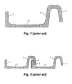
Figure 1 and 2 show cross sections of a part of a hose according to the prior art. -
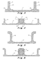
Figure 3 and 4 show cross sections of a part of a hose according to a first preferred embodiment of the invention. -
Figure 5 and 6 show cross sections of a part of a hose according to the second preferred embodiment of the invention. -
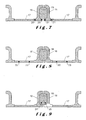
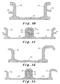
Figure 7-17 show cross sections of a part of a hose according to alternative embodiments of the invention. - Hereafter, the present invention will be described by means of specific embodiments and with reference to certain drawings, yet the invention is not limited thereto and will only be defined by the claims. The drawings provided here are merely schematic representations and are not limiting. In the drawings, dimensions of certain parts can be shown enlarged, which means that the parts involved are not depicted on scale, and this merely for illustrative purposes. The dimensions en the relative dimensions do not necessarily correspond with the practical embodiments of the invention.
- Furthermore, certain terms such as "first", "second", "third" and the like will be used in the description and claims to make a distinction between similar elements and are not necessarily meant to indicate a sequential or chronological order. The terms in question are interchangeable in the conditions appropriate therefore, and the embodiments of the invention may work in other sequences than those that are illustrated or described here.
- Furthermore, terms such as "top", "bottom", "above", "under", and the like in the description and in the claims are used for descriptive purposes and not necessarily to indicate relative positions. The said terms used are interchangeable in the conditions appropriate therefore, and the embodiments of the invention may work in other orientations than described or illustrated here.
- The term "comprising" and derivative terms, as they are used in the claims, should not be interpreted as limited to the means that are mentioned thereafter; the term does not exclude other elements or steps. The term should be interpreted as a specification of the mentioned properties, integers, steps, or components that are referred to, without excluding the presence or the addition of additional properties, integers, steps, or components, or groups thereof. The scope of an expression such as "a device comprising means A and B" is therefore not only restricted to devices that merely consist of components A and B. On the other hand, what is meant is that, as far as the present invention is concerned, the only relevant components are A and B.
-
Figure 1 and 2 respectively show a cross section of an extruded plastic profile and two adjacent windings of a hose according to the prior art. The extruded profile comprises anupright part 1, aflat web part 2 and an invertedU-shaped part 3, which forms the rib part of the hose. Theweld 4 is applied in this classic embodiment between theupright part 1 and thehanging part 5 and therib part 3. -
Figure 3 and 4 respectively show a cross section of an extruded plastic material profile and two adjacent windings of a hose according to the first embodiment of the invention. The extruded profile comprises on both sides an inverted T-shapedpart flat web part 7. The inverted T-shapedpart upright part horizontal leg web part 7. Thesehorizontal legs upright parts upright parts upright parts - The hose of
figure 3 and 4 is manufactured by successively: extruding the profile, cooling down the profile, winding the cooled profile for obtaining the adjacent windings that make up the exterior of the hose, and applying the welding material between the upright parts. The welding material is heated to a temperature above the softening temperature (semi-liquid phase), for example 150 to 270 °C, depending on the used plastic materials. -
Figure 5 and 6 respectively show a cross section of an extruded plastic profile and two adjacent windings of a hose according to a second embodiment of the invention. The extruded profile is equivalent to that offigure 3 and 4 and comprises two inverted T-shapedparts web part 17. The inverted T-shapedparts welding material 19. In this way, a hose is obtained which looks well finished on the outside. The folding can be done after the application of thewelding material 19 between theupright parts - The embodiment according to
figure 7 is substantially equivalent to that offigure 5 and 6 . The difference is that the inverted T-parts electrical conductors - The embodiment according to
figure 8 is substantially equivalent to that offigure 7 . The difference is that theelectrical conductors web part 17. - In the embodiment according to
figure 9 , twoelectrical conductors welding material 19. - In alternative embodiments, the conductors may also be installed between the upright parts and the weld.
- In the embodiment of
figure 10 and 11 , theupright parts web part 27 compriseprotrusions protrusions welding material 31 and theupright parts weld 31 can be reinforced. - In the embodiment of
figure 12 and 13 the extruded profile is equivalent to that offigure 5 and 6 and comprises two inverted T-shapedparts web part 33. The inverted T-shapedparts welding material 35 is completely enclosed. Because of this, a hose is provided that looks well finished on the outside. The folding can be done after the application of thewelding material 35 between theupright parts - In the embodiment of
figure 14 , theweb part 36 shows an unfoldable part that is provided to be unfolded when an axial tensile force is exerted onto the hose, such as to provide an elongation of the hose. - In the embodiment of
figure 15 and 16 ,web part figure 15 and 16 ) and a extended position (not depicted). Such folding parts with two stable positions are known from the hinge parts of straws, but can also be applied to this type of hose. - In all shown embodiments of the invention, the rib part has predetermined properties, more in particular choice of material and strength, predetermined for the provision of a certain hub strength to the hose.
- In all shown embodiments of the invention the web part has predetermined properties, more in particular choice of material and wall thickness, predetermined for the provision of a certain flexibility to the hose.
- The materials for the web part could be: PE, PP, PVC, polyester, PU, or other known plastic materials.
- The materials for the upright parts of the profile could be: PE, PP, polyester, PU, or other known plastic materials.
- The welding material needs to be compatible with the material used for the upright legs of the U-profile. Therefore the weld can, for example, comprise a coating of the same material.
- In the above, the invention was illustrated for the sake of simplicity on the basis of a single profile that is helically wound. It is also possible, according to the invention, to winding more than one profile next to each other in order to obtain a hose according to the invention with a multiple winding pitch, wherein the adjacent profiles need not necessarily to have the same shape with regard to their cross section. In the latter case, each profile can either be welded separately, or multiple profiles can be extruded as a whole. In this manner, it is for example possible for a hose with a pitch of three profiles, that the three profiles are connected with three different welds. But it is also possible to extrude all three different profiles as one profile, and to connect this profile with one weld.
- In the above, welding of the profiles according to the invention was described as welding by extrusion of a welding material. However, it is also possible to connect the profiles to each other by means of another method (ex. hot air, laser, IR-radiation, ...).
- In further embodiments according to the invention, it is possible to embed an electrical conductor/cable in the web part or rib part, which is connected to a sensor, which is, for example, located near a coupling element at an end of the hose and which is provided in order to measure, for example, temperature, humidity, or other parameters of the medium transported through the hose.
- In embodiments according to the invention, it is possible to provide a tube on the inside of the flexible wall (which is formed by the concatenated profiles), that extends in the longitudinal direction of the hose and which is provided to transport a second medium, or to absorb a stress relief, or to incorporate an electrical conductor/cable, or for other purposes.
- In embodiments according to the invention, it is possible to provide an electrical conductor/cable on the inside of the flexible wall (which is formed by the concatenated profiles), for example a resistance wire with a helical configuration course to heat the medium inside the hose.
- In embodiments according to the invention, it is possible to provide a wire or cable (for example an electrical conductor/cable, signalling wire or others) on the outside of the flexible wall (which is formed by the concatenated profiles) that is kept in place around the flexible wall by means of a jacket, which is applied around the outside for example by means of extrusion.
- In the embodiment of
figure 17 , the profile for manufacturing the hose is achieved in a different manner. The hose comprises theweb part 47, thewelding material 49, as well as theupright parts 48 at the ends of the profile. - As is the case with all the other embodiments mentioned herein, the profile is manufactured by co-extrusion of two
materials - In these embodiments, the
web parts 47 of the adjacent windings touch or practically touch each other. The reinforcement ribs, which are formed by theupright parts welding material 49 that is applied in between, will substantially be placed on top of theweb parts 47. Thewelding material 49 can be applied entirely between theupright parts web parts 47, but in alternative embodiments, for example solely between the parts facing each other at the top and at the bottom of theupright parts - The advantage of this construction with a rib on top of the web parts is that a hose with a smoother inside can be obtained. In addition, in case the web part is manufactured of a conductive material and the adjacent web parts are laterally in contact with each other, it is possible to obtain an improved electrical conductivity of the hose than in case the web parts are not in contact with each other (in that case, the conduction of the electrical current occurs helically, such that the length of the conducting track and the overall resistance increases proportionally to the circumference and the number of windings).
- As with the other herein described embodiments, electrical wires can be incorporated in this profile at different designated locations, or a hollow space can be provided in the profile. Instead of an electrical wire, a reinforcement wire can also be provided (for example in metal or a hard plastic material, such as in the case of stretchable hoses).
- The
web part 47 can be produced, for example, in a TPE material. The rib (upright parts
Claims (20)
- Flexible plastic hose comprising a flexible wall made out of a plurality of laterally connected windings of a helically wound profile, wherein the windings of the profile are attached to each other by means of a weld (9; 19; 31; 35; 49), wherein the profile comprises a web part (7; 17; 27; 33; 47) with predetermined properties for providing flexibility to the hose, wherein the profile ends on both sides in a upright part (6, 8; 16, 18; 26, 28; 32, 34; 46, 48), wherein the weld is located between the upright parts of adjacent windings and together with these upright parts forms a helical reinforcement rib on the flexible wall of the hose with predetermined properties for providing hub strength to the hose, characterized in that the upright parts (6, 8; 16, 18; 26, 28; 32, 34) are provided, on both sides of the profile, with a horizontal leg (62, 82) that extends in line with the web part and in the direction of the adjacent winding.
- Flexible plastic hose according to claim 1, characterized in that the upright parts (26, 28) comprise protrusions (29, 30), directed towards the adjacent winding and in such a way that they overlap each other.
- Flexible plastic hose according to any one of the previous claims, characterized in that the upright parts (16, 18) of the adjacent windings are folded towards each other at the top and substantially completely enclose the weld (19).
- Flexible plastic hose according to claim 3, characterized in that the upright parts (32, 34) of the adjacent windings overlap each other at the top.
- Flexible plastic hose according to any one of the previous claims, characterized in that the profile is essentially U-shaped.
- Flexible plastic hose according to any one of the previous claims, characterized in that the upright parts of the profile have an inverted T-shape.
- Flexible plastic hose according to any one of the previous claims, characterized in that the profile is symmetrical.
- Flexible plastic hose according to any one of the previous claims, characterized in that the flexible wall has an inside diameter of 10 to 19 mm.
- Flexible plastic hose according to any one of the previous claims, characterized in that one or more electrical conductors or cables (20, 21, 24, 25) is/are embedded in the reinforcement rib.
- Flexible plastic hose according to any one of the previous claims, characterized in that one or more electrical conductors or cables (22, 23) is/are embedded in the web part.
- Flexible plastic hose according to any one of the previous claims, characterized in that the web part comprises an unfoldable part (36) that is provided to be unfolded when an axial tensile force is exerted onto the hose, such as to provide an elongation of the hose.
- Flexible plastic hose according to any one of the previous claims, characterized in that the web part comprises collapsible parts (37, 38).
- Flexible plastic hose according to any one of the previous claims, characterized in that the upright parts and the weld are manufactured from compatible materials.
- Flexible plastic hose according to any one of the previous claims, characterized in that the upright parts and the weld are manufactured from the same material.
- Flexible plastic hose according to any one of the previous claims, characterized in that the web parts of adjacent windings of the hose are laterally in contact with each other.
- Flexible plastic hose according to claim 15, characterized in that the web parts are manufactured from a conductive material.
- Method for manufacturing a flexible plastic hose, comprising the following steps:extruding a plastic profile containing a web part with predetermined properties for providing flexibility to the hose, and which ends on both sides in an upright part,helically winding the profile, wherein the windings of the profile are attached to each other by means of a weld, for forming a flexible wall of the hose, and wherein the weld is applied between the upright parts of the adjacent windings of the profile, in such a way that the weld forms, together with the upright parts, a helical reinforcement rib on the flexible wall of the hose with predetermined properties for providing hub strength to the hose,characterized in that the upright parts (6, 8; 16, 18; 26, 28; 32, 34) are provided, on both sides of the profile, with a horizontal leg (62, 82) that extends in line with the web part and in the direction of the adjacent winding.
- Method according to claim 17, characterized in that the profile is cooled between the extrusion and the helically winding.
- Method according to claim 18, characterized in that the profile is cooled in a water tank.
- Method according to any one of the claims -17-19, characterized in that the profile is extruded at a temperature above the melting temperature of the plastic material or materials of which the profile is made, and in that the profile is cooled to a temperature below the softening temperature of these plastic material or materials, before helically winding the profile.
Priority Applications (1)
| Application Number | Priority Date | Filing Date | Title |
|---|---|---|---|
| PL12735009T PL2714371T3 (en) | 2011-05-23 | 2012-05-23 | Flexible plastic hose and method for its manufacture |
Applications Claiming Priority (2)
| Application Number | Priority Date | Filing Date | Title |
|---|---|---|---|
| BE2011/0314A BE1019918A3 (en) | 2011-05-23 | 2011-05-23 | FLEXIBLE PLASTIC HOSE AND METHOD OF MANUFACTURING THEM. |
| PCT/IB2012/052586 WO2012160524A1 (en) | 2011-05-23 | 2012-05-23 | Flexible plastic hose and method for its manufacture |
Publications (2)
| Publication Number | Publication Date |
|---|---|
| EP2714371A1 EP2714371A1 (en) | 2014-04-09 |
| EP2714371B1 true EP2714371B1 (en) | 2015-02-11 |
Family
ID=46508117
Family Applications (1)
| Application Number | Title | Priority Date | Filing Date |
|---|---|---|---|
| EP12735009.8A Active EP2714371B1 (en) | 2011-05-23 | 2012-05-23 | Flexible plastic hose and method for its manufacture |
Country Status (13)
| Country | Link |
|---|---|
| US (1) | US9230712B2 (en) |
| EP (1) | EP2714371B1 (en) |
| JP (1) | JP2014518792A (en) |
| KR (1) | KR20140031922A (en) |
| CN (1) | CN103547436B (en) |
| BE (1) | BE1019918A3 (en) |
| BR (1) | BR112013030081A2 (en) |
| CA (1) | CA2835011A1 (en) |
| ES (1) | ES2532382T3 (en) |
| MX (1) | MX2013013564A (en) |
| MY (1) | MY161230A (en) |
| PL (1) | PL2714371T3 (en) |
| WO (1) | WO2012160524A1 (en) |
Families Citing this family (13)
| Publication number | Priority date | Publication date | Assignee | Title |
|---|---|---|---|---|
| DE102008022663B4 (en) | 2008-05-07 | 2012-10-31 | Schauenburg Hose Technology Gmbh | Stretch hose |
| US9505164B2 (en) | 2009-12-30 | 2016-11-29 | Schauenburg Technology Se | Tapered helically reinforced hose and its manufacture |
| US9964238B2 (en) | 2009-01-15 | 2018-05-08 | Globalmed, Inc. | Stretch hose and hose production method |
| GB0922122D0 (en) | 2009-12-18 | 2010-02-03 | Wellstream Int Ltd | Flexible pipe having a carcass layer |
| JP6177066B2 (en) * | 2013-09-19 | 2017-08-09 | タイガースポリマー株式会社 | Synthetic resin hose |
| JP6177082B2 (en) * | 2013-10-02 | 2017-08-09 | タイガースポリマー株式会社 | Flexible hose |
| CA3033944C (en) | 2017-01-30 | 2020-02-18 | Globalmed, Inc. | Heated respiratory hose assembly |
| WO2018234235A1 (en) | 2017-06-19 | 2018-12-27 | Plastiflex Group | COMPOSITION COMPRISING POLYPROPYLENE, PROFILE AND FLEXIBLE PIPE MANUFACTURED THEREFROM |
| DE202017107890U1 (en) | 2017-12-22 | 2018-03-29 | Plastiflex Group | Flexible hose with conductive path |
| EP3524641A1 (en) | 2018-02-09 | 2019-08-14 | Plastiflex Group | Polymer material with high melt index and high flexural fatigue |
| WO2020094741A1 (en) | 2018-11-08 | 2020-05-14 | Plastiflex Group | Moisture permeable conduit for a breathing circuit |
| JP7098668B2 (en) * | 2020-02-19 | 2022-07-11 | 矢崎総業株式会社 | How to make a spiral tube |
| DE102020006493A1 (en) | 2020-10-22 | 2022-04-28 | Truplast Kunststofftechnik Gesellschaft mit beschränkter Haftung | FLEXIBLE HOSE, IN PARTICULAR VACUUM CLEANER HOSE, PROCESS FOR PRODUCTION THEREOF AND DEVICE USED THEREOF |
Family Cites Families (15)
| Publication number | Priority date | Publication date | Assignee | Title |
|---|---|---|---|---|
| US3273600A (en) * | 1963-06-10 | 1966-09-20 | Air Reduction | Flexible tube |
| US3910808A (en) | 1972-08-30 | 1975-10-07 | Steward Plastics | Apparatus for making helically wound plastic tubing |
| US4121624A (en) * | 1975-05-23 | 1978-10-24 | Fabricated Plastics, Inc. | Electrically conductive flexible tube |
| US4337800A (en) * | 1980-07-07 | 1982-07-06 | Steward Plastics, Inc. | Two piece extruded hose |
| US4375381A (en) | 1980-07-07 | 1983-03-01 | Steward Plastics, Inc. | Two piece extruded hose |
| US4354051A (en) * | 1981-04-15 | 1982-10-12 | Automation Industries, Inc. | Electrical current-carrying flexible hose and method of making same |
| US4420019A (en) * | 1982-04-05 | 1983-12-13 | Dillon Joseph C | Flexible, non-kinkable hose and method for making the same |
| US4589448A (en) * | 1984-07-25 | 1986-05-20 | Electrolux Corporation | Flexible helically wound hose with hinged strip |
| US4719945A (en) * | 1986-12-05 | 1988-01-19 | Fabricated Plastics, Inc. | Hose with composite joints |
| US4928735A (en) * | 1987-05-21 | 1990-05-29 | Fabricated Plastics, Inc. | Reinforced strip and flexible hoses produced therewith |
| JPH04160283A (en) * | 1990-10-24 | 1992-06-03 | Shiro Kanao | Hard polyvinyl chloride pipe |
| DE9408929U1 (en) * | 1994-06-01 | 1994-08-04 | Ortwin M. Zeissig GmbH & Co. KG, 45481 Mülheim | Plastic profile for hoses and pipes |
| FI107522B (en) * | 1999-11-03 | 2001-08-31 | Kwh Pipe Ab Oy | Method and apparatus for producing spirally wound tubes |
| KR20040009538A (en) * | 2002-07-24 | 2004-01-31 | 이현미 | Hose for vacuum cleaner |
| ATE330775T1 (en) * | 2004-01-24 | 2006-07-15 | Norres Schlauchtechnik Gmbh & | METHOD FOR PRODUCING A WRAPPED HOSE MADE OF THERMOPLASTIC PLASTIC |
-
2011
- 2011-05-23 BE BE2011/0314A patent/BE1019918A3/en not_active IP Right Cessation
-
2012
- 2012-05-23 JP JP2014511995A patent/JP2014518792A/en active Pending
- 2012-05-23 WO PCT/IB2012/052586 patent/WO2012160524A1/en not_active Ceased
- 2012-05-23 CN CN201280024510.1A patent/CN103547436B/en active Active
- 2012-05-23 KR KR1020137031828A patent/KR20140031922A/en not_active Withdrawn
- 2012-05-23 MX MX2013013564A patent/MX2013013564A/en active IP Right Grant
- 2012-05-23 CA CA2835011A patent/CA2835011A1/en not_active Abandoned
- 2012-05-23 EP EP12735009.8A patent/EP2714371B1/en active Active
- 2012-05-23 MY MYPI2013003926A patent/MY161230A/en unknown
- 2012-05-23 BR BR112013030081A patent/BR112013030081A2/en not_active IP Right Cessation
- 2012-05-23 ES ES12735009.8T patent/ES2532382T3/en active Active
- 2012-05-23 PL PL12735009T patent/PL2714371T3/en unknown
- 2012-05-23 US US14/119,385 patent/US9230712B2/en active Active
Also Published As
| Publication number | Publication date |
|---|---|
| US9230712B2 (en) | 2016-01-05 |
| CA2835011A1 (en) | 2012-11-29 |
| MY161230A (en) | 2017-04-14 |
| BR112013030081A2 (en) | 2016-09-20 |
| ES2532382T3 (en) | 2015-03-26 |
| PL2714371T3 (en) | 2015-05-29 |
| KR20140031922A (en) | 2014-03-13 |
| NZ617568A (en) | 2014-12-24 |
| US20140076605A1 (en) | 2014-03-20 |
| CN103547436B (en) | 2015-08-19 |
| BE1019918A3 (en) | 2013-02-05 |
| CN103547436A (en) | 2014-01-29 |
| EP2714371A1 (en) | 2014-04-09 |
| JP2014518792A (en) | 2014-08-07 |
| WO2012160524A1 (en) | 2012-11-29 |
| MX2013013564A (en) | 2014-02-27 |
Similar Documents
| Publication | Publication Date | Title |
|---|---|---|
| US9230712B2 (en) | Flexible plastic hose and method for its manufacture | |
| US7965930B2 (en) | Flexible tubing with imbedded helical conductors and method of making | |
| CN101443068B (en) | Steerable catheter using flat pull wires and method of making same | |
| US6069997A (en) | Hot pipe and apparatus for producing same | |
| US9625066B2 (en) | Helically wound plastic tubing with variable profile thickness and methods of making the same | |
| EP2494248B1 (en) | Flexible stretch hose | |
| EP3093542B1 (en) | Flexible tubing with embedded helical conductors and method of making | |
| JP2014097390A5 (en) | ||
| US20090238547A1 (en) | Heatable fluid line with a heating power which can be set | |
| US20110168287A1 (en) | Flexible tubing with dual-level imbedded helical conductors and method of making | |
| EP2788646B1 (en) | Assembled media line and method for assembling a media line comprising inner heating elements | |
| CA2380885A1 (en) | An improved duct and method of construction | |
| CN104040814B (en) | For the supporting-core of cold shrink tube | |
| NZ617568B2 (en) | Flexible plastic hose and method for its manufacture | |
| JP6037333B2 (en) | cable | |
| EP3234434B1 (en) | Heatable media line and method for producing a heatable media line | |
| CN105189087B (en) | Tubular element and the equipment for producing tubular element | |
| WO2018025454A1 (en) | Method for continuously producing resin-metal composite pipe, and resin-metal composite pipe resulting from said production method | |
| CN203805390U (en) | Bendable shaping pipe | |
| JP6959112B2 (en) | Vacuum cleaner hose | |
| KR100900338B1 (en) | Spiral support | |
| CN104733822A (en) | A radio frequency coaxial cable for antenna feeder and its manufacturing method | |
| JPH11265620A (en) | Flat cable | |
| DE102012109796B4 (en) | Locating aid for detecting plastic pipes |
Legal Events
| Date | Code | Title | Description |
|---|---|---|---|
| PUAI | Public reference made under article 153(3) epc to a published international application that has entered the european phase |
Free format text: ORIGINAL CODE: 0009012 |
|
| 17P | Request for examination filed |
Effective date: 20131203 |
|
| AK | Designated contracting states |
Kind code of ref document: A1 Designated state(s): AL AT BE BG CH CY CZ DE DK EE ES FI FR GB GR HR HU IE IS IT LI LT LU LV MC MK MT NL NO PL PT RO RS SE SI SK SM TR |
|
| DAX | Request for extension of the european patent (deleted) | ||
| GRAP | Despatch of communication of intention to grant a patent |
Free format text: ORIGINAL CODE: EPIDOSNIGR1 |
|
| INTG | Intention to grant announced |
Effective date: 20140924 |
|
| GRAS | Grant fee paid |
Free format text: ORIGINAL CODE: EPIDOSNIGR3 |
|
| GRAA | (expected) grant |
Free format text: ORIGINAL CODE: 0009210 |
|
| AK | Designated contracting states |
Kind code of ref document: B1 Designated state(s): AL AT BE BG CH CY CZ DE DK EE ES FI FR GB GR HR HU IE IS IT LI LT LU LV MC MK MT NL NO PL PT RO RS SE SI SK SM TR |
|
| REG | Reference to a national code |
Ref country code: GB Ref legal event code: FG4D |
|
| REG | Reference to a national code |
Ref country code: CH Ref legal event code: EP |
|
| REG | Reference to a national code |
Ref country code: IE Ref legal event code: FG4D |
|
| REG | Reference to a national code |
Ref country code: AT Ref legal event code: REF Ref document number: 709767 Country of ref document: AT Kind code of ref document: T Effective date: 20150315 |
|
| REG | Reference to a national code |
Ref country code: DE Ref legal event code: R096 Ref document number: 602012005247 Country of ref document: DE Effective date: 20150326 Ref country code: ES Ref legal event code: FG2A Ref document number: 2532382 Country of ref document: ES Kind code of ref document: T3 Effective date: 20150326 |
|
| REG | Reference to a national code |
Ref country code: PL Ref legal event code: T3 |
|
| REG | Reference to a national code |
Ref country code: SK Ref legal event code: T3 Ref document number: E 18172 Country of ref document: SK |
|
| REG | Reference to a national code |
Ref country code: NL Ref legal event code: VDEP Effective date: 20150211 |
|
| REG | Reference to a national code |
Ref country code: AT Ref legal event code: MK05 Ref document number: 709767 Country of ref document: AT Kind code of ref document: T Effective date: 20150211 |
|
| PG25 | Lapsed in a contracting state [announced via postgrant information from national office to epo] |
Ref country code: SE Free format text: LAPSE BECAUSE OF FAILURE TO SUBMIT A TRANSLATION OF THE DESCRIPTION OR TO PAY THE FEE WITHIN THE PRESCRIBED TIME-LIMIT Effective date: 20150211 Ref country code: NO Free format text: LAPSE BECAUSE OF FAILURE TO SUBMIT A TRANSLATION OF THE DESCRIPTION OR TO PAY THE FEE WITHIN THE PRESCRIBED TIME-LIMIT Effective date: 20150511 Ref country code: FI Free format text: LAPSE BECAUSE OF FAILURE TO SUBMIT A TRANSLATION OF THE DESCRIPTION OR TO PAY THE FEE WITHIN THE PRESCRIBED TIME-LIMIT Effective date: 20150211 Ref country code: HR Free format text: LAPSE BECAUSE OF FAILURE TO SUBMIT A TRANSLATION OF THE DESCRIPTION OR TO PAY THE FEE WITHIN THE PRESCRIBED TIME-LIMIT Effective date: 20150211 |
|
| PG25 | Lapsed in a contracting state [announced via postgrant information from national office to epo] |
Ref country code: IS Free format text: LAPSE BECAUSE OF FAILURE TO SUBMIT A TRANSLATION OF THE DESCRIPTION OR TO PAY THE FEE WITHIN THE PRESCRIBED TIME-LIMIT Effective date: 20150611 Ref country code: NL Free format text: LAPSE BECAUSE OF FAILURE TO SUBMIT A TRANSLATION OF THE DESCRIPTION OR TO PAY THE FEE WITHIN THE PRESCRIBED TIME-LIMIT Effective date: 20150211 Ref country code: RS Free format text: LAPSE BECAUSE OF FAILURE TO SUBMIT A TRANSLATION OF THE DESCRIPTION OR TO PAY THE FEE WITHIN THE PRESCRIBED TIME-LIMIT Effective date: 20150211 Ref country code: AT Free format text: LAPSE BECAUSE OF FAILURE TO SUBMIT A TRANSLATION OF THE DESCRIPTION OR TO PAY THE FEE WITHIN THE PRESCRIBED TIME-LIMIT Effective date: 20150211 Ref country code: LV Free format text: LAPSE BECAUSE OF FAILURE TO SUBMIT A TRANSLATION OF THE DESCRIPTION OR TO PAY THE FEE WITHIN THE PRESCRIBED TIME-LIMIT Effective date: 20150211 Ref country code: GR Free format text: LAPSE BECAUSE OF FAILURE TO SUBMIT A TRANSLATION OF THE DESCRIPTION OR TO PAY THE FEE WITHIN THE PRESCRIBED TIME-LIMIT Effective date: 20150512 |
|
| PG25 | Lapsed in a contracting state [announced via postgrant information from national office to epo] |
Ref country code: RO Free format text: LAPSE BECAUSE OF FAILURE TO SUBMIT A TRANSLATION OF THE DESCRIPTION OR TO PAY THE FEE WITHIN THE PRESCRIBED TIME-LIMIT Effective date: 20150211 Ref country code: DK Free format text: LAPSE BECAUSE OF FAILURE TO SUBMIT A TRANSLATION OF THE DESCRIPTION OR TO PAY THE FEE WITHIN THE PRESCRIBED TIME-LIMIT Effective date: 20150211 Ref country code: EE Free format text: LAPSE BECAUSE OF FAILURE TO SUBMIT A TRANSLATION OF THE DESCRIPTION OR TO PAY THE FEE WITHIN THE PRESCRIBED TIME-LIMIT Effective date: 20150211 |
|
| REG | Reference to a national code |
Ref country code: DE Ref legal event code: R097 Ref document number: 602012005247 Country of ref document: DE |
|
| PLBE | No opposition filed within time limit |
Free format text: ORIGINAL CODE: 0009261 |
|
| STAA | Information on the status of an ep patent application or granted ep patent |
Free format text: STATUS: NO OPPOSITION FILED WITHIN TIME LIMIT |
|
| PG25 | Lapsed in a contracting state [announced via postgrant information from national office to epo] |
Ref country code: IT Free format text: LAPSE BECAUSE OF FAILURE TO SUBMIT A TRANSLATION OF THE DESCRIPTION OR TO PAY THE FEE WITHIN THE PRESCRIBED TIME-LIMIT Effective date: 20150211 |
|
| REG | Reference to a national code |
Ref country code: CH Ref legal event code: PL |
|
| 26N | No opposition filed |
Effective date: 20151112 |
|
| PG25 | Lapsed in a contracting state [announced via postgrant information from national office to epo] |
Ref country code: CH Free format text: LAPSE BECAUSE OF NON-PAYMENT OF DUE FEES Effective date: 20150531 Ref country code: LU Free format text: LAPSE BECAUSE OF FAILURE TO SUBMIT A TRANSLATION OF THE DESCRIPTION OR TO PAY THE FEE WITHIN THE PRESCRIBED TIME-LIMIT Effective date: 20150523 Ref country code: MC Free format text: LAPSE BECAUSE OF FAILURE TO SUBMIT A TRANSLATION OF THE DESCRIPTION OR TO PAY THE FEE WITHIN THE PRESCRIBED TIME-LIMIT Effective date: 20150211 Ref country code: LI Free format text: LAPSE BECAUSE OF NON-PAYMENT OF DUE FEES Effective date: 20150531 |
|
| PG25 | Lapsed in a contracting state [announced via postgrant information from national office to epo] |
Ref country code: SI Free format text: LAPSE BECAUSE OF FAILURE TO SUBMIT A TRANSLATION OF THE DESCRIPTION OR TO PAY THE FEE WITHIN THE PRESCRIBED TIME-LIMIT Effective date: 20150211 |
|
| REG | Reference to a national code |
Ref country code: FR Ref legal event code: PLFP Year of fee payment: 5 |
|
| PG25 | Lapsed in a contracting state [announced via postgrant information from national office to epo] |
Ref country code: MT Free format text: LAPSE BECAUSE OF FAILURE TO SUBMIT A TRANSLATION OF THE DESCRIPTION OR TO PAY THE FEE WITHIN THE PRESCRIBED TIME-LIMIT Effective date: 20150211 |
|
| REG | Reference to a national code |
Ref country code: FR Ref legal event code: PLFP Year of fee payment: 6 |
|
| PG25 | Lapsed in a contracting state [announced via postgrant information from national office to epo] |
Ref country code: SM Free format text: LAPSE BECAUSE OF FAILURE TO SUBMIT A TRANSLATION OF THE DESCRIPTION OR TO PAY THE FEE WITHIN THE PRESCRIBED TIME-LIMIT Effective date: 20150211 Ref country code: HU Free format text: LAPSE BECAUSE OF FAILURE TO SUBMIT A TRANSLATION OF THE DESCRIPTION OR TO PAY THE FEE WITHIN THE PRESCRIBED TIME-LIMIT; INVALID AB INITIO Effective date: 20120523 Ref country code: BG Free format text: LAPSE BECAUSE OF FAILURE TO SUBMIT A TRANSLATION OF THE DESCRIPTION OR TO PAY THE FEE WITHIN THE PRESCRIBED TIME-LIMIT Effective date: 20150211 |
|
| PG25 | Lapsed in a contracting state [announced via postgrant information from national office to epo] |
Ref country code: CY Free format text: LAPSE BECAUSE OF FAILURE TO SUBMIT A TRANSLATION OF THE DESCRIPTION OR TO PAY THE FEE WITHIN THE PRESCRIBED TIME-LIMIT Effective date: 20150211 |
|
| REG | Reference to a national code |
Ref country code: FR Ref legal event code: PLFP Year of fee payment: 7 |
|
| PG25 | Lapsed in a contracting state [announced via postgrant information from national office to epo] |
Ref country code: PT Free format text: LAPSE BECAUSE OF FAILURE TO SUBMIT A TRANSLATION OF THE DESCRIPTION OR TO PAY THE FEE WITHIN THE PRESCRIBED TIME-LIMIT Effective date: 20150211 Ref country code: MK Free format text: LAPSE BECAUSE OF FAILURE TO SUBMIT A TRANSLATION OF THE DESCRIPTION OR TO PAY THE FEE WITHIN THE PRESCRIBED TIME-LIMIT Effective date: 20150211 |
|
| PG25 | Lapsed in a contracting state [announced via postgrant information from national office to epo] |
Ref country code: AL Free format text: LAPSE BECAUSE OF FAILURE TO SUBMIT A TRANSLATION OF THE DESCRIPTION OR TO PAY THE FEE WITHIN THE PRESCRIBED TIME-LIMIT Effective date: 20150211 |
|
| P01 | Opt-out of the competence of the unified patent court (upc) registered |
Effective date: 20230524 |
|
| PGFP | Annual fee paid to national office [announced via postgrant information from national office to epo] |
Ref country code: IE Payment date: 20240527 Year of fee payment: 13 |
|
| PGFP | Annual fee paid to national office [announced via postgrant information from national office to epo] |
Ref country code: LT Payment date: 20240502 Year of fee payment: 13 |
|
| PGFP | Annual fee paid to national office [announced via postgrant information from national office to epo] |
Ref country code: ES Payment date: 20240603 Year of fee payment: 13 |
|
| PGFP | Annual fee paid to national office [announced via postgrant information from national office to epo] |
Ref country code: CZ Payment date: 20240507 Year of fee payment: 13 |
|
| PGFP | Annual fee paid to national office [announced via postgrant information from national office to epo] |
Ref country code: SK Payment date: 20240502 Year of fee payment: 13 |
|
| PGFP | Annual fee paid to national office [announced via postgrant information from national office to epo] |
Ref country code: PL Payment date: 20240508 Year of fee payment: 13 |
|
| PGFP | Annual fee paid to national office [announced via postgrant information from national office to epo] |
Ref country code: DE Payment date: 20250529 Year of fee payment: 14 |
|
| PGFP | Annual fee paid to national office [announced via postgrant information from national office to epo] |
Ref country code: GB Payment date: 20250527 Year of fee payment: 14 |
|
| PGFP | Annual fee paid to national office [announced via postgrant information from national office to epo] |
Ref country code: BE Payment date: 20250527 Year of fee payment: 14 |
|
| PGFP | Annual fee paid to national office [announced via postgrant information from national office to epo] |
Ref country code: FR Payment date: 20250526 Year of fee payment: 14 |
|
| PGFP | Annual fee paid to national office [announced via postgrant information from national office to epo] |
Ref country code: TR Payment date: 20250515 Year of fee payment: 14 |
|
| REG | Reference to a national code |
Ref country code: LT Ref legal event code: MM4D Effective date: 20250523 |
|
| PG25 | Lapsed in a contracting state [announced via postgrant information from national office to epo] |
Ref country code: LT Free format text: LAPSE BECAUSE OF NON-PAYMENT OF DUE FEES Effective date: 20250523 |
|
| REG | Reference to a national code |
Ref country code: SK Ref legal event code: MM4A Ref document number: E 18172 Country of ref document: SK Effective date: 20250523 |
|
| PG25 | Lapsed in a contracting state [announced via postgrant information from national office to epo] |
Ref country code: CZ Free format text: LAPSE BECAUSE OF NON-PAYMENT OF DUE FEES Effective date: 20250523 |
|
| PG25 | Lapsed in a contracting state [announced via postgrant information from national office to epo] |
Ref country code: SK Free format text: LAPSE BECAUSE OF NON-PAYMENT OF DUE FEES Effective date: 20250523 |
|
| PG25 | Lapsed in a contracting state [announced via postgrant information from national office to epo] |
Ref country code: IE Free format text: LAPSE BECAUSE OF NON-PAYMENT OF DUE FEES Effective date: 20250523 |