EP2714290B1 - Screen module, processing apparatus and processing plant for mineral material - Google Patents
Screen module, processing apparatus and processing plant for mineral material Download PDFInfo
- Publication number
- EP2714290B1 EP2714290B1 EP12733168.4A EP12733168A EP2714290B1 EP 2714290 B1 EP2714290 B1 EP 2714290B1 EP 12733168 A EP12733168 A EP 12733168A EP 2714290 B1 EP2714290 B1 EP 2714290B1
- Authority
- EP
- European Patent Office
- Prior art keywords
- screen
- screen module
- screening means
- processing apparatus
- fixing
- Prior art date
- Legal status (The legal status is an assumption and is not a legal conclusion. Google has not performed a legal analysis and makes no representation as to the accuracy of the status listed.)
- Active
Links
- 239000000463 material Substances 0.000 title claims description 54
- 229910052500 inorganic mineral Inorganic materials 0.000 title claims description 30
- 239000011707 mineral Substances 0.000 title claims description 30
- 238000012216 screening Methods 0.000 claims description 104
- 230000000149 penetrating effect Effects 0.000 claims description 4
- 238000010276 construction Methods 0.000 description 9
- 238000012423 maintenance Methods 0.000 description 9
- 230000008859 change Effects 0.000 description 4
- 230000032258 transport Effects 0.000 description 4
- 230000008901 benefit Effects 0.000 description 2
- 238000004519 manufacturing process Methods 0.000 description 2
- 238000000034 method Methods 0.000 description 2
- 230000005540 biological transmission Effects 0.000 description 1
- 239000011449 brick Substances 0.000 description 1
- 238000004140 cleaning Methods 0.000 description 1
- 239000002131 composite material Substances 0.000 description 1
- 239000004035 construction material Substances 0.000 description 1
- -1 for example Substances 0.000 description 1
- 239000002184 metal Substances 0.000 description 1
- 230000008569 process Effects 0.000 description 1
- 239000011435 rock Substances 0.000 description 1
- 239000002689 soil Substances 0.000 description 1
Images
Classifications
-
- B—PERFORMING OPERATIONS; TRANSPORTING
- B07—SEPARATING SOLIDS FROM SOLIDS; SORTING
- B07B—SEPARATING SOLIDS FROM SOLIDS BY SIEVING, SCREENING, SIFTING OR BY USING GAS CURRENTS; SEPARATING BY OTHER DRY METHODS APPLICABLE TO BULK MATERIAL, e.g. LOOSE ARTICLES FIT TO BE HANDLED LIKE BULK MATERIAL
- B07B1/00—Sieving, screening, sifting, or sorting solid materials using networks, gratings, grids, or the like
- B07B1/04—Stationary flat screens
-
- B—PERFORMING OPERATIONS; TRANSPORTING
- B07—SEPARATING SOLIDS FROM SOLIDS; SORTING
- B07B—SEPARATING SOLIDS FROM SOLIDS BY SIEVING, SCREENING, SIFTING OR BY USING GAS CURRENTS; SEPARATING BY OTHER DRY METHODS APPLICABLE TO BULK MATERIAL, e.g. LOOSE ARTICLES FIT TO BE HANDLED LIKE BULK MATERIAL
- B07B1/00—Sieving, screening, sifting, or sorting solid materials using networks, gratings, grids, or the like
- B07B1/46—Constructional details of screens in general; Cleaning or heating of screens
- B07B1/4609—Constructional details of screens in general; Cleaning or heating of screens constructional details of screening surfaces or meshes
- B07B1/4627—Repairing of screening surfaces
-
- B—PERFORMING OPERATIONS; TRANSPORTING
- B07—SEPARATING SOLIDS FROM SOLIDS; SORTING
- B07B—SEPARATING SOLIDS FROM SOLIDS BY SIEVING, SCREENING, SIFTING OR BY USING GAS CURRENTS; SEPARATING BY OTHER DRY METHODS APPLICABLE TO BULK MATERIAL, e.g. LOOSE ARTICLES FIT TO BE HANDLED LIKE BULK MATERIAL
- B07B1/00—Sieving, screening, sifting, or sorting solid materials using networks, gratings, grids, or the like
- B07B1/46—Constructional details of screens in general; Cleaning or heating of screens
- B07B1/4609—Constructional details of screens in general; Cleaning or heating of screens constructional details of screening surfaces or meshes
- B07B1/4645—Screening surfaces built up of modular elements
-
- B—PERFORMING OPERATIONS; TRANSPORTING
- B07—SEPARATING SOLIDS FROM SOLIDS; SORTING
- B07B—SEPARATING SOLIDS FROM SOLIDS BY SIEVING, SCREENING, SIFTING OR BY USING GAS CURRENTS; SEPARATING BY OTHER DRY METHODS APPLICABLE TO BULK MATERIAL, e.g. LOOSE ARTICLES FIT TO BE HANDLED LIKE BULK MATERIAL
- B07B1/00—Sieving, screening, sifting, or sorting solid materials using networks, gratings, grids, or the like
- B07B1/46—Constructional details of screens in general; Cleaning or heating of screens
- B07B1/4609—Constructional details of screens in general; Cleaning or heating of screens constructional details of screening surfaces or meshes
- B07B1/4663—Multi-layer screening surfaces
-
- B—PERFORMING OPERATIONS; TRANSPORTING
- B07—SEPARATING SOLIDS FROM SOLIDS; SORTING
- B07B—SEPARATING SOLIDS FROM SOLIDS BY SIEVING, SCREENING, SIFTING OR BY USING GAS CURRENTS; SEPARATING BY OTHER DRY METHODS APPLICABLE TO BULK MATERIAL, e.g. LOOSE ARTICLES FIT TO BE HANDLED LIKE BULK MATERIAL
- B07B1/00—Sieving, screening, sifting, or sorting solid materials using networks, gratings, grids, or the like
- B07B1/46—Constructional details of screens in general; Cleaning or heating of screens
- B07B1/48—Stretching devices for screens
- B07B1/49—Stretching devices for screens stretching more than one screen or screen section by the same or different stretching means
-
- B—PERFORMING OPERATIONS; TRANSPORTING
- B07—SEPARATING SOLIDS FROM SOLIDS; SORTING
- B07B—SEPARATING SOLIDS FROM SOLIDS BY SIEVING, SCREENING, SIFTING OR BY USING GAS CURRENTS; SEPARATING BY OTHER DRY METHODS APPLICABLE TO BULK MATERIAL, e.g. LOOSE ARTICLES FIT TO BE HANDLED LIKE BULK MATERIAL
- B07B2201/00—Details applicable to machines for screening using sieves or gratings
- B07B2201/04—Multiple deck screening devices comprising one or more superimposed screens
Definitions
- the invention relates to a screen module, a processing apparatus and a processing plant which are suitable for mineral material screening.
- the invention relates particularly, though not exclusively, to a multi-deck screen in which screen means equipped with holes or openings such as screen elements, screen meshes or perforated screen plates are arranged on top of each other.
- each screen deck is fixed above cross beams of the deck.
- the cross beams fixed at their ends to the body of the screen such as a screen basket, are arranged crosswise relative to the direction of movement of the material to be screened.
- the successive cross beams are connected to each other by longitudinal supports which are arranged in the movement direction of the material to be screened that is parallel to the length of the screen.
- a screening means forming the screen deck is formed for example of a mesh or a perforated plate.
- the screen decks are tensioned on the longitudinal supports and tensioned from perimeters of the screen deck to the body of the screen at the sides, for example, to a side plate comprised by the body.
- a known four-deck screen is shown in Fig. 1 .
- mineral material means soil, for example, rock material, which is gained from the earth by excavating, exploding or crushing, and construction material such as bricks and concrete.
- a two deck screen module according to the preamble of claim 1 is disclosed in the document US-A-1,997,713 .
- An object of the invention is to create a screen solution by which problems of the prior art can be eliminated or at least reduced.
- a particular object is to lower a screening apparatus.
- a particular object is to lighten a screening apparatus.
- a particular object is to create a multipurpose screen module having a simple construction.
- a particular object is to simplify change of a screening means.
- a particular object is to reduce material used and work in production and maintenance of a screen apparatus:
- a screen module for mineral material as defined in claim 1.
- the screen module comprises as support structures cross beams for fixing the screen module to a side body of the mineral material processing apparatus and for fixing the upper screening means above the cross beams, and lower longitudinal supports which are fixed below the cross beams for supporting the lower screening means below the lower longitudinal supports:
- the screen module comprises as support structures longitudinal beams for fixing the screen module to an end body of the mineral material processing apparatus and upper longitudinal supports fixed above the longitudinal beams for supporting the upper screening means above the longitudinal beams, and lower longitudinal supports which are fixed below the longitudinal beams for supporting the lower screening means below the lower longitudinal supports.
- the screen module comprises an auxiliary body for fixing the screen module to the body of the mineral material processing apparatus and the cross beams fixed to the auxiliary body.
- the screen module comprises a lower support region which is defined by the height of the lower longitudinal supports and the lower screening means is fixable at its at least two sides to the body or the auxiliary body for fixing the lower screening means relative to the cross beams.
- the screen module comprises upper longitudinal supports which are fixed above the cross beams and by which the cross beams supporting the upper longitudinal supports are fixed to each other, and an upper support region for supporting the upper screening means on the upper longitudinal supports, which upper support region is defined by the height of the upper longitudinal supports, and the upper screening means is fixable at its at least two sides to the body or the auxiliary body for fixing the upper screening means relative to the cross beams.
- the screening means comprises a screen mesh, a screen element or a perforated screen plate.
- the height of the lower longitudinal supports is defining a penetrating distance between the cross beams and the lower screening plate for the through-flow path of the material to be processed.
- changeable wear plates are fixed on a surface of the lower longitudinal supports.
- the screen module comprises first cross beams and second cross beams.
- the first cross beams may be on a higher height and the second cross beams may be on a lower height or the first and second cross beams may be adjacent on the same level.
- the lower longitudinal supports are fixed to the second cross beams under the second cross beams.
- the upper longitudinal supports are fixed to the first cross beams above the first cross beams.
- a processing apparatus for mineral material screening as defined in claim 9 comprising a body and at least one screen module according to claims 1 to 8.
- the screen module is fixed to the body of the processing apparatus.
- An upper screening means may be fixed to the screen module.
- An upper and a lower screening means may be fixed to the screen module.
- a lower screening means may be fixed to the screen module.
- the screening means may be fixed at least at its/their two opposite sides to the body or an auxiliary body comprised by the screen module.
- the upper and/or the lower screening means comprises in its sides gripping points
- the processing apparatus comprises fixing means for fixing the screening means through the gripping points to the body or the auxiliary body.
- the gripping point of the screening means comprises a hook-like form for the gripping of the fixing means.
- the fixing means comprises a fixing member enabling a fixing and opening movement by which the fixing means is movable to and from the body or the auxiliary body, for supporting the screening means such that the screening means is kept supported by the fixing means in a non-tensioned state of the fixing means.
- the fixing member comprises a screw with long stroke which may be a bolt.
- two screen modules are arranged on top of each other in the processing apparatus.
- at least two screen modules are arranged successively in the processing apparatus.
- screen decks of the successive screen modules are arranged in an angle position relative to each other.
- one screening means is arranged in an upper screening module or a lower screening module.
- only one screening means is arranged above the cross beams in the lowermost screen module of a processing apparatus which comprises screen modules on top of each other.
- a mineral material processing plant as defined in claim 15 comprising a screen module according to claims 1 to 8 or a processing apparatus according to claims 9 to 14.
- the processing plant is a fixed plant, an independent movable plant or a plant which is transportable on road.
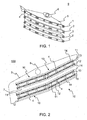
- Fig. 1 shows a 4-deck screen 9 having screen decks 1, 2, 3 and 3' which each are fixed above the cross beams 4 of the decks.
- the cross beams 4 are fixed to the body 5 of the screen at their ends and arranged crosswise relative to the movement direction of the material to be screened.
- a screen deck is formed of for example a mesh or a perforated plate.
- the screen decks are fixed at their sides to a side plate of the body 5 at the sides of the screen deck. Own cross beams 4 are required for each screen deck.
- a vibration apparatus 6 (for example, an eccentric actuator) of the screen is fixed to the body 5.
- the vibration apparatus 6 may be equipped with one axis or with two or more axes.
- the own cross beams required by each screen deck make the screen heavy and high. Additionally, three separate maintenance spaces are required for changing the screen decks 2, 3, and 3'.
- the maintenance spaces shall be dimensioned such that the changing of the screen decks is safe and sufficiently quick.
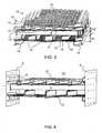
- Fig. 2 shows a 4-deck screen 100 according to a preferable embodiment of the invention.
- the screen is formed of screen modules 10 fixable to the body (screen basket) 5 which are described in more detail in connection with Fig. 3 .
- the screen 100 comprises additionally vibration dampers (not shown in the Fig.) such as springs in each corner of the screen by which traveling of vibration from the body of the screen to support structures such as for example the body of a processing apparatus supporting the body is dampened.
- Two screen decks are fixed to the same cross beam 4 in the screen module solution.
- Two upper screen modules 10 are fixed successively on a first height and two lower screen modules 10 are fixed successively on a lower second height to the 4-deck screen 100 shown in the Figure.
- the screen modules 10 in both levels comprise two screen decks.
- a maintenance space 7 is left between the upper and lower screen modules which can be utilized when a screening means is fixed at its sides to the body 5, for example to body plates, at the sides of the screen 100.
- the maintenance space 7 is formed between a lower screen deck 12 of an upper screen module and an upper screen deck 11 of a lower screen module.
- Sufficiently space can be arranged for the height of the maintenance space 7, for example about a half meter, such that meshes of the second and third decks can be changed. Accordingly, only one maintenance space is required for the four-deck screen of the invention.
- the fourth deck can be changed from below the screen, for example at a conveyor or a hopper of a mineral material processing plant 400.
- a compact screen the height and weight of which can be reduced compared to known solutions, can be formed by one screen module, by several screen modules arranged in one level and screen modules which are arranged on top of each other.
- a multipurpose module construction which comprises two screen decks can be formed which can be placed on top of each other and/or successively.
- every second increase of height due to the maintenance space can be avoided compared to the prior art.
- some of the screen decks can be left without a screening means wherein it is further possible to save in weight and height compared to the prior art.
- a single screen module can also be used in place of a single-deck screen wherein a very low two-deck screen is gained.
- Used screens 100 and processing plants can be modernized by the screen modules and functions thereof can be made more effective. The making more effective can be gained by placing more screen decks than prior to the space which is utilized. By a more compact screen than prior which is assembled of the screen modules mineral material processing can be made more effective also in freeing space to be utilized by other apparatuses of the process.
- Two successive screen modules 10, particularly the successive screen decks of the screen modules, are arranged in an angled position relative to each other in Fig. 2 .
- the screen deck used as a screening means is formed of for example one or more meshes, mesh or perforated plate elements, or perforated plates.
- Fig. 3 shows a screen module 10 which comprises cross beams 4 to be fixed to the body (not shown in the Figure) above which is fixed an upper screening means 11 and below which is fixed a lower screening means 12. It can be observed in Fig. 3 that the upper screening means 11 and the lower screening means 12 of the screen module 10 do not necessarily form a unitary planar screening region because a preferable fixing method of the screening mesh or plate by tensioning over the cross beams 4 may form to the screening means such a screening region which is divided in several planar regions. Two successive screen modules 10 are arranged in an angled position relative to each other in Fig. 3 .
- a profile height 4" of the cross beam 4 is selected such that the cross beam 4 is bearing the load caused by the own mass of the screen module, by the mass of the mineral material located the screen decks and by the loading of the mineral material.
- the profile height 4" is about 120 mm in one preferable embodiment.
- the screen module 10 comprises upper longitudinal supports 13 above the cross beams 4. Five upper longitudinal supports 13 are shown side by side in Fig. 3 .
- the cross beams 4 are fixed to each other by the upper longitudinal supports 13 which are fixed above the cross beams.
- the amount of the upper longitudinal supports can alternate among others according to application, rigidity of the screening means and size of the screen module.
- the upper screening means 11 such as a screen mesh is fixable at its sides to for example the body 5 of the screen 100 of Fig. 2 .
- Upper surfaces of the upper longitudinal supports 13 or corresponding uppermost points in connection with the upper longitudinal supports are defining an upper support region 13' for supporting the upper screening means 11 on the upper longitudinal supports.
- the screening means 11 is mounted on the upper longitudinal supports 13 and fixed to the body from the sides, located at the sides of the upper screening means 11, by fixing means 14 wherein the screening means is tensioned against the upper longitudinal supports.
- a desired mounting distance 13" between the cross beams and the upper screening means 11 can be formed by the upper longitudinal supports 13 for straining the upper screening means.
- the mounting distance 13" is about 150 mm in a preferable embodiment.
- the screen module 10 comprises lower longitudinal supports 15 below the cross beams 4. Lower surfaces of the lower longitudinal supports 15 or corresponding lowermost points in connection with the lower longitudinal supports (lowermost points of wear plates 16) are defining a lower support region 15' for supporting the lower screening means 12 to and below the lower longitudinal supports. Thus, no maintenance space is required to be left between these two screen decks (11, 12), only sufficiently space for the material to be screened. Wear plates 16 are arranged on side surfaces of the lower longitudinal supports for slowing down wear of the lower longitudinal supports. The material to be screened can be compartmented by the lower longitudinal supports 15.
- a desired penetrating distance 15" for a through-flow path of the material flow above the lower screening means 12 can be formed between the cross beams 4 and the lower screening means 12 (under the cross beams).
- the penetrating distance 15" of the through-flow path is about 150 to 200 mm.
- the material to be screened can be guided by the lower longitudinal supports 15 to proceed in a desired direction, preferably longitudinally with reference to the screen module.
- the amount of the lower longitudinal supports can alternate among others according to application, rigidity of the screening means and size of the screen module.
- the lower longitudinal supports are easy detachable from and attachable to the cross beams that they can be changed because of the wear of the material to be screened.
- the lower screening means 12 such as the screen mesh is fixable at its sides, over the lower longitudinal supports 15, to the body at the side of the screen.
- the lower screening means 12 is mounted from below against the lower longitudinal supports 15/wear plates 16 and fixed to the body from the sides of the screening means by fixing means 14 wherein the screening means is tensioned towards the cross beams 4.
- the tensioning of the upper 11 and lower 12 screening means relative to the cross beams 4 is reducing unnecessary vibration and wear of parts of the apparatus, particularly the wear of the screening means 11, 12. Additionally, the screening becomes more effective when deflection of the screen mesh is minor. In some cases the same screening means can be used for the upper and the lower fixing. If necessary, the lower screening means can be fixed centrally to the lower longitudinal support 15 because the lower screening means is bearing load. Thus, wear can be reduced.
- the upper 11 and/or the lower 12 screening means can be fixed to the body 5 (or to an auxiliary body shown in Fig. 4 ) from at least two sides at the side, from at least two end sides or from at least two sides at the side and at the end.
- the fixing means 14 is fixable to the body of the screen by long fixing members such as bolts.
- the fixing members 14 are tensioned wherein the fixing members 14 are pulling the sides of the screening means 11, 12 towards the body of the screen and the screening means is tensioned against the cross beams 4.
- the fixing means of the lower screening means 12 are preferably formed such that the fixing means are holding in support the mesh which is mounted to be supported wherein the screening means does not drop on the person making the change. When the fixing means is/are opened the screening means is not wholly detached but is lowering slightly downwards and can be changed quickly.
- Fig. 4 shows a screen module 10' which comprises an auxiliary body 5' which can be fixed to a body of a processing plant (not shown in the Figs.).
- the cross beams 4 are fixed to the auxiliary body 5'.
- the upper screening means 11 is fixed above and the lower screening means 12 is fixed below the cross beams 4.
- the screening means 11, 12 are fixed at their sides to the auxiliary body wherein the screen module 10' is formed a self-supporting construction.
- the screening means 11, 12 are fixed to the auxiliary body by long-stroke screws 17.
- the self-supporting screen module can be assembled outside the processing plant and mounted as one unit.
- the module construction together with the auxiliary body enables a more liberal and wide-ranging location of the screen decks relative to each other.
- the body and/or the auxiliary body 5' of the screen may comprise many alternative fixing points wherein the angle between successive screen elements and/or screen elements on top of each other can be changed according to demands of each material to be screened.
- each screen module comprises an own vibration apparatus.
- Each auxiliary body is acting as an own screen basket and successive modules are preferably located such relative to each other that side walls of a preceding screen basket are extending inside side walls of a latter screen basket wherein the flowing material does not drop uncontrolled from between the screen baskets.
- Rotation speed and/or force of stroke and, in case of a directing vibration screen additionally direction of stroke, is/are possible to be adjusted separately by the before described arrangement.
- FIGS. 5a to 5c Alternative embodiments for support structures of the screen are shown in Figs. 5a to 5c wherein the support structures are longitudinal beams and fixed to end structures 503 of the screen 500.
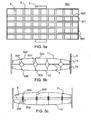
- Fig. 5a shows a top view of the construction of the screen (alternatively a bottom view).
- the screen 500 comprises a body structure, that is a side plate 5 and an end plate 503. Further the screen comprises longitudinal beams 501 which are fixed to the end plate 503 and correspondingly to an end plate at the second end of the screen by a bolt or another corresponding fixing.
- Upper longitudinal supports 502, 502' (lower longitudinal supports 506, 506') are fixed above (alternatively or additionally below) the longitudinal beams 501 for supporting an upper screening means 11 (a lower screening means 12) above (below) the longitudinal supports 502, 502'.
- the upper screen mesh 11 and correspondingly the lower screen mesh 12 are fixed to the body 5 or correspondingly to the auxiliary body of the screen by fixing means 14.
- the longitudinal beam can be according to Fig. 5b a square beam 501 and produced for example of metal or a composite material.
- the longitudinal beam can also be a parallelogram box beam 501' what is advantageous particularly when it is desired that the beam withstands vertical loads. Further the form of such a beam is preferably directed more in the flow direction of the material to be screened than a fully square beam.
- Fig. 5c shows a cross section of a screen construction in which the longitudinal beam 505 is a plate-like beam such as an I-beam.
- the longitudinal beam is fixed to the cross beams 4 and the side most cross beams are fixed at their first ends to the body or the auxiliary body of the screen and at their second ends to the longitudinal beam 505 preferably by a flange joint 504.
- the next cross beam is fixed between the longitudinal beams 505 and 505' by a corresponding way for example by flange joints 504'.
- the longitudinal beams 501, 505 are preferably higher at the centre region of the screen and lower at the side regions wherein in the case of a side-tensioned screen mesh a curved form is gained which is required for an even tensioning.
- the longitudinal beams 501, 505 shown in Fig. 5c are forming at the same time a load bearing support structure and the upper and lower longitudinal supports for supporting the screening means in connection with the support structure.
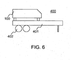
- Fig. 6 shows a mineral material processing plant 400 which is suitable for mineral material screening for example in open pits.
- the processing plant 400 comprises a body 401 and one or more screens 100 as mineral material processing apparatuses fixed to the body.
- a wheel base 402 is fixed to the body 401 for enabling independent moving.
- the processing plant may comprise additionally a crusher such as a jaw, gyratory, cone crusher or a vertical or horizontal shaft impactor (not shown in the Figures) as the mineral material processing apparatus.
- the material to be processed may be loaded for example by a loader directly on the screen where from the material can be lead to the crusher. Alternatively the material may be loaded on a conveyor which transports the material to the screen.
- the processing plant may comprise as the mineral material processing apparatus also a feeder (not shown in the Figures) for feeding the screened material from the screen to the crusher and the processing plant may comprise one or more conveyors (not shown in the Figures) for transporting the crushed and/or screened material further to one or more piles beside the processing plant.
- the processing plant may further comprise an energy source such as an electric, diesel or other type motor and a transmission from the energy source to the crusher.
- the movement may be enabled also by legs, runners or rollers.
- the processing plant can track based be transported on road by a carriage or a corresponding transport arrangement. Wheel based it may be towable on road preferably by a truck.
- the screen 100 may also be placed in a fixed mineral material processing plant.
Description
- The invention relates to a screen module, a processing apparatus and a processing plant which are suitable for mineral material screening. The invention relates particularly, though not exclusively, to a multi-deck screen in which screen means equipped with holes or openings such as screen elements, screen meshes or perforated screen plates are arranged on top of each other.
- In a known screen each screen deck is fixed above cross beams of the deck. The cross beams, fixed at their ends to the body of the screen such as a screen basket, are arranged crosswise relative to the direction of movement of the material to be screened. The successive cross beams are connected to each other by longitudinal supports which are arranged in the movement direction of the material to be screened that is parallel to the length of the screen. A screening means forming the screen deck is formed for example of a mesh or a perforated plate. The screen decks are tensioned on the longitudinal supports and tensioned from perimeters of the screen deck to the body of the screen at the sides, for example, to a side plate comprised by the body. A known four-deck screen is shown in
Fig. 1 . Own cross beams are required for each screen deck. There is required much space between the decks in the known solution that a change of a screen mesh is possible. Therefore, screens with several decks are very high and heavy. The large height is complicating handling and transport of mineral material processing apparatuses, increasing the height of mineral material processing apparatuses, and the loading height of the screen may become high. Placing to an allowable load height, particularly of wheel based screening plants towable on road or track based screening plants transportable on a carriage, is often complicated in case of multi-deck screens. - In this connection mineral material means soil, for example, rock material, which is gained from the earth by excavating, exploding or crushing, and construction material such as bricks and concrete.
- A two deck screen module according to the preamble of
claim 1 is disclosed in the documentUS-A-1,997,713 . - An object of the invention is to create a screen solution by which problems of the prior art can be eliminated or at least reduced. A particular object is to lower a screening apparatus. A particular object is to lighten a screening apparatus. A particular object is to create a multipurpose screen module having a simple construction. A particular object is to simplify change of a screening means. A particular object is to reduce material used and work in production and maintenance of a screen apparatus:
- According to a first aspect of the invention there is provided a screen module for mineral material as defined in
claim 1. - Longitudinal supports against which lower perforated plates are mounted are known, for example from
FR-A-1.089.947 - Preferably the screen module comprises as support structures cross beams for fixing the screen module to a side body of the mineral material processing apparatus and for fixing the upper screening means above the cross beams, and lower longitudinal supports which are fixed below the cross beams for supporting the lower screening means below the lower longitudinal supports:
- Preferably the screen module comprises as support structures longitudinal beams for fixing the screen module to an end body of the mineral material processing apparatus and upper longitudinal supports fixed above the longitudinal beams for supporting the upper screening means above the longitudinal beams, and lower longitudinal supports which are fixed below the longitudinal beams for supporting the lower screening means below the lower longitudinal supports.
- Preferably the screen module comprises an auxiliary body for fixing the screen module to the body of the mineral material processing apparatus and the cross beams fixed to the auxiliary body.
- Preferably the screen module comprises a lower support region which is defined by the height of the lower longitudinal supports and the lower screening means is fixable at its at least two sides to the body or the auxiliary body for fixing the lower screening means relative to the cross beams.
- Preferably the screen module comprises upper longitudinal supports which are fixed above the cross beams and by which the cross beams supporting the upper longitudinal supports are fixed to each other, and an upper support region for supporting the upper screening means on the upper longitudinal supports, which upper support region is defined by the height of the upper longitudinal supports, and the upper screening means is fixable at its at least two sides to the body or the auxiliary body for fixing the upper screening means relative to the cross beams.
- Preferably the screening means comprises a screen mesh, a screen element or a perforated screen plate.
- Preferably the height of the lower longitudinal supports is defining a penetrating distance between the cross beams and the lower screening plate for the through-flow path of the material to be processed.
- Preferably changeable wear plates are fixed on a surface of the lower longitudinal supports.
- Preferably the screen module comprises first cross beams and second cross beams. The first cross beams may be on a higher height and the second cross beams may be on a lower height or the first and second cross beams may be adjacent on the same level. Preferably the lower longitudinal supports are fixed to the second cross beams under the second cross beams. Preferably the upper longitudinal supports are fixed to the first cross beams above the first cross beams.
- According to a second aspect of the invention there is provided a processing apparatus for mineral material screening as defined in
claim 9 comprising a body and at least one screen module according toclaims 1 to 8. - Preferably the screen module is fixed to the body of the processing apparatus. An upper screening means may be fixed to the screen module. An upper and a lower screening means may be fixed to the screen module. A lower screening means may be fixed to the screen module. The screening means may be fixed at least at its/their two opposite sides to the body or an auxiliary body comprised by the screen module.
- Preferably the upper and/or the lower screening means comprises in its sides gripping points, and the processing apparatus comprises fixing means for fixing the screening means through the gripping points to the body or the auxiliary body. Preferably the gripping point of the screening means comprises a hook-like form for the gripping of the fixing means. Preferably the fixing means comprises a fixing member enabling a fixing and opening movement by which the fixing means is movable to and from the body or the auxiliary body, for supporting the screening means such that the screening means is kept supported by the fixing means in a non-tensioned state of the fixing means. Preferably the fixing member comprises a screw with long stroke which may be a bolt.
- Preferably two screen modules are arranged on top of each other in the processing apparatus. Preferably at least two screen modules are arranged successively in the processing apparatus. Preferably screen decks of the successive screen modules are arranged in an angle position relative to each other. Preferably in a processing apparatus which comprises two screen modules on top of each other, one screening means is arranged in an upper screening module or a lower screening module. Preferably only one screening means is arranged above the cross beams in the lowermost screen module of a processing apparatus which comprises screen modules on top of each other.
- According to a third aspect of the invention there is provided a mineral material processing plant as defined in
claim 15 comprising a screen module according toclaims 1 to 8 or a processing apparatus according toclaims 9 to 14. Preferably the processing plant is a fixed plant, an independent movable plant or a plant which is transportable on road. - Further preferable embodiments and advantages of the invention are shown in the following description and claims. In a screen solution in which two screen decks are fixed to the same cross beam, use of space can be reduced so that the change of the screen mesh is possible. Thus, height and weight of multi-deck screens, for example, four-deck screens can be reduced. Lowering of the screen makes easier the handling and transport of mineral material processing apparatuses, and it is possible to lower the loading height of the screen. A lighter construction of the screen is leading to reduced production costs. In the solution mounting of the lower screen deck to the cross beam of the screen module can be arranged user friendly.
- The invention will be described, by way of example, with reference to the accompanying drawings, in which:
-
Fig. 1 shows a known four-deck screen; -
Fig. 2 shows a side view of a four-deck screen which is formed of screen modules according to a preferable embodiment of the invention; -
Fig. 3 shows a front view of a structure of a screen module according to a first preferable embodiment of the invention; -
Fig. 4 shows a front view of a structure of a screen module according to a second preferable embodiment of the invention; -
Fig. 5a shows a top view of a structure of a screen module according to a third preferable embodiment of the invention; -
Fig. 5b shows a front view in cross section of a first variant of the screen module ofFig. 5a ; -
Fig. 5c shows a second variant of the screen module ofFig. 5a ; and -
Fig. 6 shows a movable mineral material processing plant comprising a screen. - In the following description, like numbers denote like elements. It should be appreciated that the illustrated drawings are not entirely in scale, and that the drawings mainly serve the purpose of illustrating some example embodiments of the invention.
-
Fig. 1 shows a 4-deck screen 9 havingscreen decks body 5 of the screen at their ends and arranged crosswise relative to the movement direction of the material to be screened. A screen deck is formed of for example a mesh or a perforated plate. The screen decks are fixed at their sides to a side plate of thebody 5 at the sides of the screen deck. Own cross beams 4 are required for each screen deck. A vibration apparatus 6 (for example, an eccentric actuator) of the screen is fixed to thebody 5. Thevibration apparatus 6 may be equipped with one axis or with two or more axes. The own cross beams required by each screen deck make the screen heavy and high. Additionally, three separate maintenance spaces are required for changing thescreen decks -
Fig. 2 shows a 4-deck screen 100 according to a preferable embodiment of the invention. The screen is formed ofscreen modules 10 fixable to the body (screen basket) 5 which are described in more detail in connection withFig. 3 . Typically, thescreen 100 comprises additionally vibration dampers (not shown in the Fig.) such as springs in each corner of the screen by which traveling of vibration from the body of the screen to support structures such as for example the body of a processing apparatus supporting the body is dampened. Two screen decks are fixed to thesame cross beam 4 in the screen module solution. Twoupper screen modules 10 are fixed successively on a first height and twolower screen modules 10 are fixed successively on a lower second height to the 4-deck screen 100 shown in the Figure. Thescreen modules 10 in both levels comprise two screen decks. - When screen modules are mounted on top of each other in the screen, a
maintenance space 7 is left between the upper and lower screen modules which can be utilized when a screening means is fixed at its sides to thebody 5, for example to body plates, at the sides of thescreen 100. Themaintenance space 7 is formed between alower screen deck 12 of an upper screen module and anupper screen deck 11 of a lower screen module. Sufficiently space can be arranged for the height of themaintenance space 7, for example about a half meter, such that meshes of the second and third decks can be changed. Accordingly, only one maintenance space is required for the four-deck screen of the invention. The fourth deck can be changed from below the screen, for example at a conveyor or a hopper of a mineralmaterial processing plant 400. - A compact screen, the height and weight of which can be reduced compared to known solutions, can be formed by one screen module, by several screen modules arranged in one level and screen modules which are arranged on top of each other. By one screen module a multipurpose module construction which comprises two screen decks can be formed which can be placed on top of each other and/or successively. In case of the screen modules on top of each other every second increase of height due to the maintenance space can be avoided compared to the prior art. In some cases some of the screen decks can be left without a screening means wherein it is further possible to save in weight and height compared to the prior art. A single screen module can also be used in place of a single-deck screen wherein a very low two-deck screen is gained.
Used screens 100 and processing plants can be modernized by the screen modules and functions thereof can be made more effective. The making more effective can be gained by placing more screen decks than prior to the space which is utilized. By a more compact screen than prior which is assembled of the screen modules mineral material processing can be made more effective also in freeing space to be utilized by other apparatuses of the process. - Two
successive screen modules 10, particularly the successive screen decks of the screen modules, are arranged in an angled position relative to each other inFig. 2 . The screen deck used as a screening means is formed of for example one or more meshes, mesh or perforated plate elements, or perforated plates. -
Fig. 3 shows ascreen module 10 which comprisescross beams 4 to be fixed to the body (not shown in the Figure) above which is fixed an upper screening means 11 and below which is fixed a lower screening means 12. It can be observed inFig. 3 that the upper screening means 11 and the lower screening means 12 of thescreen module 10 do not necessarily form a unitary planar screening region because a preferable fixing method of the screening mesh or plate by tensioning over the cross beams 4 may form to the screening means such a screening region which is divided in several planar regions. Twosuccessive screen modules 10 are arranged in an angled position relative to each other inFig. 3 . - A
profile height 4" of thecross beam 4 is selected such that thecross beam 4 is bearing the load caused by the own mass of the screen module, by the mass of the mineral material located the screen decks and by the loading of the mineral material. Theprofile height 4" is about 120 mm in one preferable embodiment. - The
screen module 10 comprises upperlongitudinal supports 13 above the cross beams 4. Five upperlongitudinal supports 13 are shown side by side inFig. 3 . The cross beams 4 are fixed to each other by the upperlongitudinal supports 13 which are fixed above the cross beams. The amount of the upper longitudinal supports can alternate among others according to application, rigidity of the screening means and size of the screen module. The upper screening means 11 such as a screen mesh is fixable at its sides to for example thebody 5 of thescreen 100 ofFig. 2 . - Upper surfaces of the upper
longitudinal supports 13 or corresponding uppermost points in connection with the upper longitudinal supports are defining an upper support region 13' for supporting the upper screening means 11 on the upper longitudinal supports. The screening means 11 is mounted on the upperlongitudinal supports 13 and fixed to the body from the sides, located at the sides of the upper screening means 11, by fixingmeans 14 wherein the screening means is tensioned against the upper longitudinal supports. A desired mountingdistance 13" between the cross beams and the upper screening means 11 can be formed by the upperlongitudinal supports 13 for straining the upper screening means. The mountingdistance 13" is about 150 mm in a preferable embodiment. - The
screen module 10 comprises lowerlongitudinal supports 15 below the cross beams 4. Lower surfaces of the lowerlongitudinal supports 15 or corresponding lowermost points in connection with the lower longitudinal supports (lowermost points of wear plates 16) are defining a lower support region 15' for supporting the lower screening means 12 to and below the lower longitudinal supports. Thus, no maintenance space is required to be left between these two screen decks (11, 12), only sufficiently space for the material to be screened. Wearplates 16 are arranged on side surfaces of the lower longitudinal supports for slowing down wear of the lower longitudinal supports. The material to be screened can be compartmented by the lower longitudinal supports 15. When the height of the lower longitudinal supports is selected in a suitable way, a desiredpenetrating distance 15" for a through-flow path of the material flow above the lower screening means 12 can be formed between the cross beams 4 and the lower screening means 12 (under the cross beams). The penetratingdistance 15" of the through-flow path is about 150 to 200 mm. The material to be screened can be guided by the lowerlongitudinal supports 15 to proceed in a desired direction, preferably longitudinally with reference to the screen module. The amount of the lower longitudinal supports can alternate among others according to application, rigidity of the screening means and size of the screen module. Preferably the lower longitudinal supports are easy detachable from and attachable to the cross beams that they can be changed because of the wear of the material to be screened. The lower screening means 12 such as the screen mesh is fixable at its sides, over the lowerlongitudinal supports 15, to the body at the side of the screen. The lower screening means 12 is mounted from below against the lowerlongitudinal supports 15/wear plates 16 and fixed to the body from the sides of the screening means by fixingmeans 14 wherein the screening means is tensioned towards the cross beams 4. - The tensioning of the upper 11 and lower 12 screening means relative to the cross beams 4 is reducing unnecessary vibration and wear of parts of the apparatus, particularly the wear of the screening means 11, 12. Additionally, the screening becomes more effective when deflection of the screen mesh is minor. In some cases the same screening means can be used for the upper and the lower fixing. If necessary, the lower screening means can be fixed centrally to the lower
longitudinal support 15 because the lower screening means is bearing load. Thus, wear can be reduced. - The upper 11 and/or the lower 12 screening means can be fixed to the body 5 (or to an auxiliary body shown in
Fig. 4 ) from at least two sides at the side, from at least two end sides or from at least two sides at the side and at the end. - Preferably there are grips at the sides of the screening means, for example a hook-like form, which can be gripped by a fixing means 14, preferably by an edge of a fixing means 14 comprising a trough-like profile. Preferably the fixing means 14 is fixable to the body of the screen by long fixing members such as bolts. In connection with the mounting the screening means 11, 12 is moved at its sides longitudinally with reference to the screen on a gripping surface of the fixing means and the fixing members are tensioned wherein the fixing
members 14 are pulling the sides of the screening means 11, 12 towards the body of the screen and the screening means is tensioned against the cross beams 4. The fixing means of the lower screening means 12 are preferably formed such that the fixing means are holding in support the mesh which is mounted to be supported wherein the screening means does not drop on the person making the change. When the fixing means is/are opened the screening means is not wholly detached but is lowering slightly downwards and can be changed quickly. -
Fig. 4 shows a screen module 10' which comprises an auxiliary body 5' which can be fixed to a body of a processing plant (not shown in the Figs.). The cross beams 4 are fixed to the auxiliary body 5'. The upper screening means 11 is fixed above and the lower screening means 12 is fixed below the cross beams 4. The screening means 11, 12 are fixed at their sides to the auxiliary body wherein the screen module 10' is formed a self-supporting construction. The screening means 11, 12 are fixed to the auxiliary body by long-stroke screws 17. In order to understand the construction of the screen module 10' it is referred toFigs. 2 and3 . The self-supporting screen module can be assembled outside the processing plant and mounted as one unit. - The module construction together with the auxiliary body enables a more liberal and wide-ranging location of the screen decks relative to each other. The body and/or the auxiliary body 5' of the screen may comprise many alternative fixing points wherein the angle between successive screen elements and/or screen elements on top of each other can be changed according to demands of each material to be screened.
- Alternatively the module construction with the auxiliary body can be utilized such that each screen module comprises an own vibration apparatus. Each auxiliary body is acting as an own screen basket and successive modules are preferably located such relative to each other that side walls of a preceding screen basket are extending inside side walls of a latter screen basket wherein the flowing material does not drop uncontrolled from between the screen baskets. Rotation speed and/or force of stroke and, in case of a directing vibration screen additionally direction of stroke, is/are possible to be adjusted separately by the before described arrangement.
- Alternative embodiments for support structures of the screen are shown in
Figs. 5a to 5c wherein the support structures are longitudinal beams and fixed to endstructures 503 of thescreen 500. -
Fig. 5a shows a top view of the construction of the screen (alternatively a bottom view). Thescreen 500 comprises a body structure, that is aside plate 5 and anend plate 503. Further the screen compriseslongitudinal beams 501 which are fixed to theend plate 503 and correspondingly to an end plate at the second end of the screen by a bolt or another corresponding fixing. - Upper
longitudinal supports 502, 502' (lowerlongitudinal supports 506, 506') are fixed above (alternatively or additionally below) thelongitudinal beams 501 for supporting an upper screening means 11 (a lower screening means 12) above (below) thelongitudinal supports 502, 502'. - As it is described already before, the
upper screen mesh 11 and correspondingly thelower screen mesh 12 are fixed to thebody 5 or correspondingly to the auxiliary body of the screen by fixingmeans 14. - The longitudinal beam can be according to
Fig. 5b asquare beam 501 and produced for example of metal or a composite material. Alternatively the longitudinal beam can also be a parallelogram box beam 501' what is advantageous particularly when it is desired that the beam withstands vertical loads. Further the form of such a beam is preferably directed more in the flow direction of the material to be screened than a fully square beam. -
Fig. 5c shows a cross section of a screen construction in which thelongitudinal beam 505 is a plate-like beam such as an I-beam. The longitudinal beam is fixed to the cross beams 4 and the side most cross beams are fixed at their first ends to the body or the auxiliary body of the screen and at their second ends to thelongitudinal beam 505 preferably by aflange joint 504. The next cross beam is fixed between thelongitudinal beams 505 and 505' by a corresponding way for example by flange joints 504'. - The
longitudinal beams longitudinal beams Fig. 5c are forming at the same time a load bearing support structure and the upper and lower longitudinal supports for supporting the screening means in connection with the support structure. -
Fig. 6 shows a mineralmaterial processing plant 400 which is suitable for mineral material screening for example in open pits. Theprocessing plant 400 comprises abody 401 and one ormore screens 100 as mineral material processing apparatuses fixed to the body. Awheel base 402 is fixed to thebody 401 for enabling independent moving. - The processing plant may comprise additionally a crusher such as a jaw, gyratory, cone crusher or a vertical or horizontal shaft impactor (not shown in the Figures) as the mineral material processing apparatus. The material to be processed may be loaded for example by a loader directly on the screen where from the material can be lead to the crusher. Alternatively the material may be loaded on a conveyor which transports the material to the screen. The processing plant may comprise as the mineral material processing apparatus also a feeder (not shown in the Figures) for feeding the screened material from the screen to the crusher and the processing plant may comprise one or more conveyors (not shown in the Figures) for transporting the crushed and/or screened material further to one or more piles beside the processing plant. The processing plant may further comprise an energy source such as an electric, diesel or other type motor and a transmission from the energy source to the crusher.
- Instead of the
wheel base 402 the movement may be enabled also by legs, runners or rollers. The processing plant can track based be transported on road by a carriage or a corresponding transport arrangement. Wheel based it may be towable on road preferably by a truck. Thescreen 100 may also be placed in a fixed mineral material processing plant. - The foregoing description provides non-limiting examples of some embodiments of the invention. It is clear to a person skilled in the art that the invention is not restricted to details presented, but that the invention can be implemented in other equivalent means. Some of the features of the above-disclosed embodiments may be used to advantage without the use of other features.
- As such, the foregoing description shall be considered as merely illustrative of principles of the invention, and not in limitation thereof. Hence, the scope of the invention is only restricted by the appended patent claims.
Claims (15)
- A two-deck mineral material screen module (10) comprising- support structures (4, 501, 505) for fixing the screen module to a body (5) of a mineral material processing apparatus (100), and- an upper screening means (11) which is fixed above the support structures,- lower longitudinal supports (15, 506, 506') which are fixed below the support structures (4, 501, 501', 505),- a lower screening means (12) which is fixed below the lower longitudinal
supports,
characterized in that
the lower screening means (12) is mounted from below against the lower longitudinal supports (15, 506, 506') which are forming together with the lower screening means a through-flow path of the material flow above the lower screening means so as to guide material to be screened on the lower screening means longitudinally with reference to the screen module. - The screen module according to claim 1, characterized in that the screen module (10) comprises- cross beams (4) for fixing the screen module to a side body (5) of the mineral material processing apparatus (100) and the upper screening means (11) is fixed above the cross beams, and- lower longitudinal supports (15) which are fixed below the cross beams (4) and supporting the lower screening means (12) below the lower longitudinal supports.
- The screen module according to claim 1, characterized in that the screen module (10) comprises- longitudinal beams (501, 505) for fixing the screen module to an end body (5) of the mineral material processing apparatus (100) and upper longitudinal supports fixed above the longitudinal beams and supporting the upper screening means (11) above the longitudinal beams, and- lower longitudinal supports which are fixed below the longitudinal beams (501, 505) and supporting the lower screening means (12) below the lower longitudinal supports.
- The screen module according to any of claims 1 to 3, characterized in that the screen module (10) comprises- an auxiliary body (5') for fixing the screen module (10) to the body (5) of the mineral material processing apparatus (100), and- the cross beams (4) are fixed to the auxiliary body.
- The screen module according to any of claims 1 to 4, characterized in that the screen module (10) comprises- a lower support region (15') which is defined by the height (15") of the lower longitudinal supports (15) and the lower screening means (12) is fixable at its at least two sides to the body (5) or the auxiliary body (5') for fixing the lower screening means relative to the cross beams (4).
- The screen module according to any of claims 1 to 5, characterized in that the screen module (10) comprises- upper longitudinal supports (13) which are fixed above the cross beams (4) and by which the cross beams supporting the upper longitudinal supports are fixed to each other, and- an upper support region (13') which is supporting the upper screening means on the upper longitudinal supports, which upper support region is defined by the height of the upper longitudinal supports, and the upper screening means is fixable at its at least two sides to the body (5) or the auxiliary body (5') for fixing the upper screening means relative to the cross beams.
- The screen module according to any of claims 1 to 6, characterized in that the height of the lower longitudinal supports (15) is defining a penetrating distance (15") between the cross beams (4) and the lower screening plate (12) of the through-flow path of the material to be processed.
- The screen module according to any of claims 1 to 8, characterized in that changeable wear plates (16) are fixed on a surface of the lower longitudinal supports (15).
- A processing apparatus (100) for mineral material screening comprising a body (5), characterized in that the processing apparatus (100) comprises at least one screen module (10) according to any of claims 1 to 8.
- The processing apparatus according to claim 9, characterized in that the screen module (10) is fixed to the body (5); and the screening means is/are fixed at least at its/their two sides to the body (5) of the processing apparatus or an auxiliary body (5') comprised by the screen module (10).
- The processing apparatus according to claim 9 or 10, characterized in that the upper (11) and/or the lower (12) screening means comprises in its sides gripping points, and the processing apparatus comprises fixing means (14) which are fixing the screening means (11, 12) through the gripping points to the body (5) or the auxiliary body (5'), and preferably the gripping point comprises a hook-like
form which is gripping the fixing means (14). - The processing apparatus according to claim 11, characterized in that the fixing means (14) comprises a fixing member (17) enabling a fixing and opening movement by which the fixing means is movable to and from the body (5) or the auxiliary body (5'), the fixing member supporting the screening means (11, 12) such that the screening means is kept supported by the fixing means in a non-tensioned state of the fixing means, and preferably the fixing member (17) comprises a screw with long stroke.
- The processing apparatus according to any of claims 9 to 12, characterized in that two screen modules (10) are arranged on top of each other in the processing apparatus.
- The processing apparatus according to any of claims 9 to 13, characterized in that at least two screen modules (10) are arranged successively in the processing apparatus, and preferably the screen decks of the successive screen modules (10) are arranged in an angle position relative to each other.
- A mineral material processing plant (400) comprising a screen module (10) according to any of claims 1 to 8 or a processing apparatus (100) according to any of claims 9 to 14.
Applications Claiming Priority (2)
| Application Number | Priority Date | Filing Date | Title |
|---|---|---|---|
| FI20115510A FI20115510A (en) | 2011-05-24 | 2011-05-24 | SIGNING MODULE, PROCESSING DEVICE AND MINERAL MATERIALS PROCESSING |
| PCT/FI2012/050498 WO2012160259A1 (en) | 2011-05-24 | 2012-05-24 | Screen module, processing apparatus and processing plant for mineral material |
Publications (2)
| Publication Number | Publication Date |
|---|---|
| EP2714290A1 EP2714290A1 (en) | 2014-04-09 |
| EP2714290B1 true EP2714290B1 (en) | 2015-08-12 |
Family
ID=44071635
Family Applications (1)
| Application Number | Title | Priority Date | Filing Date |
|---|---|---|---|
| EP12733168.4A Active EP2714290B1 (en) | 2011-05-24 | 2012-05-24 | Screen module, processing apparatus and processing plant for mineral material |
Country Status (10)
| Country | Link |
|---|---|
| US (1) | US9120128B2 (en) |
| EP (1) | EP2714290B1 (en) |
| JP (1) | JP6001651B2 (en) |
| CN (1) | CN103619495B (en) |
| AU (1) | AU2012260777B2 (en) |
| BR (1) | BR112013030148B1 (en) |
| FI (1) | FI20115510A (en) |
| RU (1) | RU2625577C2 (en) |
| WO (1) | WO2012160259A1 (en) |
| ZA (1) | ZA201308610B (en) |
Families Citing this family (11)
| Publication number | Priority date | Publication date | Assignee | Title |
|---|---|---|---|---|
| FR2999665B1 (en) * | 2012-12-18 | 2015-01-02 | Vicat | GRID FOR THE EQUIPMENT OF A PUMPS PUMP |
| CN103240222B (en) * | 2013-04-28 | 2015-04-08 | 中国矿业大学 | Large synchronous hyperstatic net-beam vibrating screen |
| WO2015027321A1 (en) * | 2013-08-27 | 2015-03-05 | Fp Canmechanica Inc. | Dual screen assembly for vibrating screening machine |
| CN105057203A (en) * | 2015-09-02 | 2015-11-18 | 四川金锋建设有限公司 | Using method of vibrating screen plate |
| CN106115079A (en) * | 2016-06-16 | 2016-11-16 | 成都森洁商贸有限公司 | The placement basket plucked for blueberry fresh fruit |
| WO2018032067A1 (en) * | 2016-08-17 | 2018-02-22 | Fonseca Helio | Arrangement introduced into a grid of blade type for ore-grading screens |
| GB201621279D0 (en) * | 2016-12-14 | 2017-01-25 | Axiom Process Ltd | Shale shaker basket system |
| CN106733636A (en) * | 2017-01-16 | 2017-05-31 | 中铁三局集团有限公司 | A kind of improved filler screening plant |
| CN110526602B (en) * | 2018-05-23 | 2024-01-02 | 四川马氏窑技术发展有限公司 | Mixing lime kiln with fuel layering treatment function |
| CN111215313A (en) * | 2018-11-24 | 2020-06-02 | 浙江晟达机械有限公司 | Gravity type material self-screening device |
| RU194754U1 (en) * | 2019-10-14 | 2019-12-23 | Общество с ограниченной ответственностью "Сибирская техническая компания" | Vibrating screen |
Family Cites Families (23)
| Publication number | Priority date | Publication date | Assignee | Title |
|---|---|---|---|---|
| US1997713A (en) | 1932-08-08 | 1935-04-16 | Tyler Co W S | Screen and method of making same |
| US2395138A (en) | 1942-06-18 | 1946-02-19 | Day J H Co | High-speed sifter |
| US2497902A (en) | 1945-12-06 | 1950-02-21 | Richmond Mfg Company | Screen clearer for gyratory sifters |
| FR1089947A (en) * | 1953-04-09 | 1955-03-24 | Screening device and its applications | |
| US3101314A (en) * | 1961-09-21 | 1963-08-20 | Louis W Johnson | Screen deck construction |
| FR2070375A5 (en) * | 1969-12-03 | 1971-09-10 | Dragon App | Vibrating screen - with neoprene covered members |
| SU492317A1 (en) * | 1974-03-29 | 1975-11-25 | Государственный проектно-конструкторский институт "Гипромашуглеобогащение" | Bolt |
| SU820904A1 (en) * | 1975-05-04 | 1981-04-15 | Всесоюзный Научно-Исследовательскийинститут Строительного И Дорожногомашиностроения | Screen |
| SU865429A1 (en) * | 1979-11-28 | 1981-09-23 | Государственный Проектно-Конструкторский И Экспериментальный Институт По Обогатительному Оборудованию "Гипромашобогащение" | Jigging screen |
| SU880513A1 (en) * | 1980-01-04 | 1981-11-15 | Всесоюзный Научно-Исследовательский Институт Строительного И Дорожного Машиностроения (Вниистройдормаш) | Screen sieve |
| US4802591A (en) * | 1986-08-29 | 1989-02-07 | Rotex, Inc. | Louvered chip screener |
| JPH0691228A (en) * | 1992-09-16 | 1994-04-05 | Mitsubishi Kasei Corp | Classification of coal |
| US5816413A (en) | 1995-09-08 | 1998-10-06 | W.S. Tyler, Canada | Wire screen deck having replaceable modular screen panels |
| JP3431080B2 (en) * | 1996-06-28 | 2003-07-28 | メトソ ミネラルズ(ミドルバラ) インコーポレイテッド | Material separation device and its exchange kit |
| US5746322A (en) | 1996-07-02 | 1998-05-05 | Action Equipment Co., Inc. | Vibratory finger screen with lateral wedge members |
| JP2000343038A (en) * | 1999-06-07 | 2000-12-12 | Sanshin Kogyo Kk | Sieve with tightening device and vibrating sieve using same |
| CA2370549C (en) * | 1999-06-24 | 2009-01-13 | Tuboscope I/P Inc. | A screen, a panel for a screen, a shale shaker and a method of screening |
| US6267246B1 (en) * | 2000-02-14 | 2001-07-31 | Western Wire Works, Inc. | Screening system for screening or diverting particulate material |
| FI119921B (en) | 2004-11-10 | 2009-05-15 | Metso Minerals Oy | Mobile mineral processing unit body and multifunction clamp |
| SE0501232L (en) * | 2005-05-31 | 2006-10-17 | Sandvik Intellectual Property | Viewing device |
| SE529114C2 (en) * | 2005-12-13 | 2007-05-02 | Sandvik Intellectual Property | Viewing device |
| SE529115E (en) * | 2005-12-14 | 2014-09-17 | Sandvik Intellectual Property | Viewing device |
| US7918346B2 (en) * | 2008-05-31 | 2011-04-05 | Mark Roppo | Vibrating screen tensioning apparatus and method |
-
2011
- 2011-05-24 FI FI20115510A patent/FI20115510A/en not_active Application Discontinuation
-
2012
- 2012-05-24 AU AU2012260777A patent/AU2012260777B2/en active Active
- 2012-05-24 US US14/119,466 patent/US9120128B2/en active Active
- 2012-05-24 JP JP2014511921A patent/JP6001651B2/en active Active
- 2012-05-24 RU RU2013156006A patent/RU2625577C2/en active
- 2012-05-24 CN CN201280024905.1A patent/CN103619495B/en active Active
- 2012-05-24 WO PCT/FI2012/050498 patent/WO2012160259A1/en active Application Filing
- 2012-05-24 BR BR112013030148-1A patent/BR112013030148B1/en active IP Right Grant
- 2012-05-24 EP EP12733168.4A patent/EP2714290B1/en active Active
-
2013
- 2013-11-15 ZA ZA2013/08610A patent/ZA201308610B/en unknown
Also Published As
| Publication number | Publication date |
|---|---|
| CN103619495A (en) | 2014-03-05 |
| US20140166546A1 (en) | 2014-06-19 |
| RU2013156006A (en) | 2015-06-27 |
| RU2625577C2 (en) | 2017-07-17 |
| AU2012260777B2 (en) | 2017-02-02 |
| BR112013030148A2 (en) | 2016-09-27 |
| FI20115510A (en) | 2012-11-25 |
| US9120128B2 (en) | 2015-09-01 |
| FI20115510A0 (en) | 2011-05-24 |
| EP2714290A1 (en) | 2014-04-09 |
| CN103619495B (en) | 2017-03-22 |
| JP6001651B2 (en) | 2016-10-05 |
| ZA201308610B (en) | 2014-08-27 |
| JP2014515308A (en) | 2014-06-30 |
| WO2012160259A1 (en) | 2012-11-29 |
| BR112013030148B1 (en) | 2020-06-30 |
Similar Documents
| Publication | Publication Date | Title |
|---|---|---|
| EP2714290B1 (en) | Screen module, processing apparatus and processing plant for mineral material | |
| AU2012260777A1 (en) | Screen module, processing apparatus and processing plant for mineral material | |
| EP2890505B1 (en) | Vibrating screen | |
| US9757771B2 (en) | Vibratory apparatus with dynamic balancer and balancing method | |
| CN103934204A (en) | Presorting device for waste disposal | |
| CN105592928A (en) | A mineral material processing plant and a method for operating a processing plant | |
| RU2241550C1 (en) | Vibratory screen | |
| US11020768B2 (en) | Vibratory classifiers | |
| CN107008645A (en) | Inclined double-deck excited vibration screen device | |
| CN201008850Y (en) | Vertical magnetic separator | |
| CN205074208U (en) | Shaking screen | |
| WO2018031517A1 (en) | Vibratory classifiers | |
| AU590549B2 (en) | Breaking bulk material into certain size & screening | |
| CN203991266U (en) | A kind of rod screening feeding machine | |
| CN100594991C (en) | Vibrating no-mesh screening machien and working method thereof | |
| Wei et al. | Design of vibrating screen separation equipment for powder materials | |
| KR100694766B1 (en) | Power screen | |
| CN104070007A (en) | Rod screening and feeding machine | |
| CN219400483U (en) | Layout platform for three-dimensional crushing and shaping system | |
| CN201454830U (en) | Two-stage strip grid type feed sieving machine | |
| GB2561452A (en) | An improved vibrating screener | |
| CN103464371A (en) | Unpowered anti-blocking grate bar slide sieve | |
| EP1987893A1 (en) | Particle sorting device | |
| RU32006U1 (en) | Vibrating screen | |
| DE10053845A1 (en) | Improvements for sieve boxes |
Legal Events
| Date | Code | Title | Description |
|---|---|---|---|
| PUAI | Public reference made under article 153(3) epc to a published international application that has entered the european phase |
Free format text: ORIGINAL CODE: 0009012 |
|
| 17P | Request for examination filed |
Effective date: 20131217 |
|
| AK | Designated contracting states |
Kind code of ref document: A1 Designated state(s): AL AT BE BG CH CY CZ DE DK EE ES FI FR GB GR HR HU IE IS IT LI LT LU LV MC MK MT NL NO PL PT RO RS SE SI SK SM TR |
|
| DAX | Request for extension of the european patent (deleted) | ||
| GRAP | Despatch of communication of intention to grant a patent |
Free format text: ORIGINAL CODE: EPIDOSNIGR1 |
|
| INTG | Intention to grant announced |
Effective date: 20150320 |
|
| GRAS | Grant fee paid |
Free format text: ORIGINAL CODE: EPIDOSNIGR3 |
|
| GRAA | (expected) grant |
Free format text: ORIGINAL CODE: 0009210 |
|
| AK | Designated contracting states |
Kind code of ref document: B1 Designated state(s): AL AT BE BG CH CY CZ DE DK EE ES FI FR GB GR HR HU IE IS IT LI LT LU LV MC MK MT NL NO PL PT RO RS SE SI SK SM TR |
|
| REG | Reference to a national code |
Ref country code: GB Ref legal event code: FG4D |
|
| REG | Reference to a national code |
Ref country code: CH Ref legal event code: EP |
|
| REG | Reference to a national code |
Ref country code: AT Ref legal event code: REF Ref document number: 741649 Country of ref document: AT Kind code of ref document: T Effective date: 20150815 |
|
| REG | Reference to a national code |
Ref country code: IE Ref legal event code: FG4D |
|
| REG | Reference to a national code |
Ref country code: DE Ref legal event code: R096 Ref document number: 602012009596 Country of ref document: DE |
|
| REG | Reference to a national code |
Ref country code: SE Ref legal event code: TRGR |
|
| REG | Reference to a national code |
Ref country code: NO Ref legal event code: T2 Effective date: 20150812 |
|
| REG | Reference to a national code |
Ref country code: LT Ref legal event code: MG4D |
|
| REG | Reference to a national code |
Ref country code: NL Ref legal event code: MP Effective date: 20150812 |
|
| PG25 | Lapsed in a contracting state [announced via postgrant information from national office to epo] |
Ref country code: GR Free format text: LAPSE BECAUSE OF FAILURE TO SUBMIT A TRANSLATION OF THE DESCRIPTION OR TO PAY THE FEE WITHIN THE PRESCRIBED TIME-LIMIT Effective date: 20151113 Ref country code: LV Free format text: LAPSE BECAUSE OF FAILURE TO SUBMIT A TRANSLATION OF THE DESCRIPTION OR TO PAY THE FEE WITHIN THE PRESCRIBED TIME-LIMIT Effective date: 20150812 Ref country code: LT Free format text: LAPSE BECAUSE OF FAILURE TO SUBMIT A TRANSLATION OF THE DESCRIPTION OR TO PAY THE FEE WITHIN THE PRESCRIBED TIME-LIMIT Effective date: 20150812 |
|
| PG25 | Lapsed in a contracting state [announced via postgrant information from national office to epo] |
Ref country code: PL Free format text: LAPSE BECAUSE OF FAILURE TO SUBMIT A TRANSLATION OF THE DESCRIPTION OR TO PAY THE FEE WITHIN THE PRESCRIBED TIME-LIMIT Effective date: 20150812 Ref country code: RS Free format text: LAPSE BECAUSE OF FAILURE TO SUBMIT A TRANSLATION OF THE DESCRIPTION OR TO PAY THE FEE WITHIN THE PRESCRIBED TIME-LIMIT Effective date: 20150812 Ref country code: HR Free format text: LAPSE BECAUSE OF FAILURE TO SUBMIT A TRANSLATION OF THE DESCRIPTION OR TO PAY THE FEE WITHIN THE PRESCRIBED TIME-LIMIT Effective date: 20150812 Ref country code: IS Free format text: LAPSE BECAUSE OF FAILURE TO SUBMIT A TRANSLATION OF THE DESCRIPTION OR TO PAY THE FEE WITHIN THE PRESCRIBED TIME-LIMIT Effective date: 20151212 Ref country code: ES Free format text: LAPSE BECAUSE OF FAILURE TO SUBMIT A TRANSLATION OF THE DESCRIPTION OR TO PAY THE FEE WITHIN THE PRESCRIBED TIME-LIMIT Effective date: 20150812 Ref country code: PT Free format text: LAPSE BECAUSE OF FAILURE TO SUBMIT A TRANSLATION OF THE DESCRIPTION OR TO PAY THE FEE WITHIN THE PRESCRIBED TIME-LIMIT Effective date: 20151214 |
|
| PG25 | Lapsed in a contracting state [announced via postgrant information from national office to epo] |
Ref country code: NL Free format text: LAPSE BECAUSE OF FAILURE TO SUBMIT A TRANSLATION OF THE DESCRIPTION OR TO PAY THE FEE WITHIN THE PRESCRIBED TIME-LIMIT Effective date: 20150812 |
|
| PG25 | Lapsed in a contracting state [announced via postgrant information from national office to epo] |
Ref country code: EE Free format text: LAPSE BECAUSE OF FAILURE TO SUBMIT A TRANSLATION OF THE DESCRIPTION OR TO PAY THE FEE WITHIN THE PRESCRIBED TIME-LIMIT Effective date: 20150812 Ref country code: DK Free format text: LAPSE BECAUSE OF FAILURE TO SUBMIT A TRANSLATION OF THE DESCRIPTION OR TO PAY THE FEE WITHIN THE PRESCRIBED TIME-LIMIT Effective date: 20150812 Ref country code: CZ Free format text: LAPSE BECAUSE OF FAILURE TO SUBMIT A TRANSLATION OF THE DESCRIPTION OR TO PAY THE FEE WITHIN THE PRESCRIBED TIME-LIMIT Effective date: 20150812 Ref country code: SK Free format text: LAPSE BECAUSE OF FAILURE TO SUBMIT A TRANSLATION OF THE DESCRIPTION OR TO PAY THE FEE WITHIN THE PRESCRIBED TIME-LIMIT Effective date: 20150812 |
|
| REG | Reference to a national code |
Ref country code: DE Ref legal event code: R097 Ref document number: 602012009596 Country of ref document: DE |
|
| REG | Reference to a national code |
Ref country code: FR Ref legal event code: PLFP Year of fee payment: 5 |
|
| PG25 | Lapsed in a contracting state [announced via postgrant information from national office to epo] |
Ref country code: RO Free format text: LAPSE BECAUSE OF FAILURE TO SUBMIT A TRANSLATION OF THE DESCRIPTION OR TO PAY THE FEE WITHIN THE PRESCRIBED TIME-LIMIT Effective date: 20150812 |
|
| PLBE | No opposition filed within time limit |
Free format text: ORIGINAL CODE: 0009261 |
|
| STAA | Information on the status of an ep patent application or granted ep patent |
Free format text: STATUS: NO OPPOSITION FILED WITHIN TIME LIMIT |
|
| 26N | No opposition filed |
Effective date: 20160513 |
|
| PG25 | Lapsed in a contracting state [announced via postgrant information from national office to epo] |
Ref country code: SI Free format text: LAPSE BECAUSE OF FAILURE TO SUBMIT A TRANSLATION OF THE DESCRIPTION OR TO PAY THE FEE WITHIN THE PRESCRIBED TIME-LIMIT Effective date: 20150812 Ref country code: BE Free format text: LAPSE BECAUSE OF NON-PAYMENT OF DUE FEES Effective date: 20160531 |
|
| PG25 | Lapsed in a contracting state [announced via postgrant information from national office to epo] |
Ref country code: BE Free format text: LAPSE BECAUSE OF FAILURE TO SUBMIT A TRANSLATION OF THE DESCRIPTION OR TO PAY THE FEE WITHIN THE PRESCRIBED TIME-LIMIT Effective date: 20150812 Ref country code: LU Free format text: LAPSE BECAUSE OF FAILURE TO SUBMIT A TRANSLATION OF THE DESCRIPTION OR TO PAY THE FEE WITHIN THE PRESCRIBED TIME-LIMIT Effective date: 20160524 |
|
| REG | Reference to a national code |
Ref country code: CH Ref legal event code: PL |
|
| PG25 | Lapsed in a contracting state [announced via postgrant information from national office to epo] |
Ref country code: LI Free format text: LAPSE BECAUSE OF NON-PAYMENT OF DUE FEES Effective date: 20160531 Ref country code: CH Free format text: LAPSE BECAUSE OF NON-PAYMENT OF DUE FEES Effective date: 20160531 |
|
| REG | Reference to a national code |
Ref country code: IE Ref legal event code: MM4A |
|
| REG | Reference to a national code |
Ref country code: FR Ref legal event code: PLFP Year of fee payment: 6 |
|
| PG25 | Lapsed in a contracting state [announced via postgrant information from national office to epo] |
Ref country code: IE Free format text: LAPSE BECAUSE OF NON-PAYMENT OF DUE FEES Effective date: 20160524 |
|
| REG | Reference to a national code |
Ref country code: AT Ref legal event code: UEP Ref document number: 741649 Country of ref document: AT Kind code of ref document: T Effective date: 20150812 |
|
| REG | Reference to a national code |
Ref country code: FR Ref legal event code: PLFP Year of fee payment: 7 |
|
| PG25 | Lapsed in a contracting state [announced via postgrant information from national office to epo] |
Ref country code: SM Free format text: LAPSE BECAUSE OF FAILURE TO SUBMIT A TRANSLATION OF THE DESCRIPTION OR TO PAY THE FEE WITHIN THE PRESCRIBED TIME-LIMIT Effective date: 20150812 Ref country code: CY Free format text: LAPSE BECAUSE OF FAILURE TO SUBMIT A TRANSLATION OF THE DESCRIPTION OR TO PAY THE FEE WITHIN THE PRESCRIBED TIME-LIMIT Effective date: 20150812 Ref country code: HU Free format text: LAPSE BECAUSE OF FAILURE TO SUBMIT A TRANSLATION OF THE DESCRIPTION OR TO PAY THE FEE WITHIN THE PRESCRIBED TIME-LIMIT; INVALID AB INITIO Effective date: 20120524 |
|
| PG25 | Lapsed in a contracting state [announced via postgrant information from national office to epo] |
Ref country code: MT Free format text: LAPSE BECAUSE OF NON-PAYMENT OF DUE FEES Effective date: 20160531 Ref country code: TR Free format text: LAPSE BECAUSE OF FAILURE TO SUBMIT A TRANSLATION OF THE DESCRIPTION OR TO PAY THE FEE WITHIN THE PRESCRIBED TIME-LIMIT Effective date: 20150812 Ref country code: MK Free format text: LAPSE BECAUSE OF FAILURE TO SUBMIT A TRANSLATION OF THE DESCRIPTION OR TO PAY THE FEE WITHIN THE PRESCRIBED TIME-LIMIT Effective date: 20150812 Ref country code: MC Free format text: LAPSE BECAUSE OF FAILURE TO SUBMIT A TRANSLATION OF THE DESCRIPTION OR TO PAY THE FEE WITHIN THE PRESCRIBED TIME-LIMIT Effective date: 20150812 |
|
| PG25 | Lapsed in a contracting state [announced via postgrant information from national office to epo] |
Ref country code: BG Free format text: LAPSE BECAUSE OF FAILURE TO SUBMIT A TRANSLATION OF THE DESCRIPTION OR TO PAY THE FEE WITHIN THE PRESCRIBED TIME-LIMIT Effective date: 20150812 |
|
| PG25 | Lapsed in a contracting state [announced via postgrant information from national office to epo] |
Ref country code: AL Free format text: LAPSE BECAUSE OF FAILURE TO SUBMIT A TRANSLATION OF THE DESCRIPTION OR TO PAY THE FEE WITHIN THE PRESCRIBED TIME-LIMIT Effective date: 20150812 |
|
| REG | Reference to a national code |
Ref country code: NO Ref legal event code: CHAD Owner name: METSO OUTOTEC FINLAND OY, FI |
|
| REG | Reference to a national code |
Ref country code: AT Ref legal event code: HC Ref document number: 741649 Country of ref document: AT Kind code of ref document: T Owner name: METSO OUTOTEC FINLAND OY, FI Effective date: 20221122 |
|
| REG | Reference to a national code |
Ref country code: DE Ref legal event code: R081 Ref document number: 602012009596 Country of ref document: DE Owner name: METSO MINERALS, INC., FI Free format text: FORMER OWNER: METSO MINERALS, INC., HELSINKI, FI |
|
| P01 | Opt-out of the competence of the unified patent court (upc) registered |
Effective date: 20230517 |
|
| PGFP | Annual fee paid to national office [announced via postgrant information from national office to epo] |
Ref country code: NO Payment date: 20230510 Year of fee payment: 12 Ref country code: IT Payment date: 20230412 Year of fee payment: 12 Ref country code: DE Payment date: 20230404 Year of fee payment: 12 Ref country code: FR Payment date: 20230421 Year of fee payment: 12 |
|
| PGFP | Annual fee paid to national office [announced via postgrant information from national office to epo] |
Ref country code: SE Payment date: 20230412 Year of fee payment: 12 Ref country code: FI Payment date: 20230513 Year of fee payment: 12 Ref country code: AT Payment date: 20230425 Year of fee payment: 12 |
|
| PGFP | Annual fee paid to national office [announced via postgrant information from national office to epo] |
Ref country code: GB Payment date: 20230406 Year of fee payment: 12 |